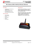
1
STRAINSERT WIRELESS LOAD CELL
RECEIVER / TRANSMITTER
MODEL J-Unit1
USER MANUAL
Strainsert Company
12 Union Hill Road
West Conshohocken, PA 18914
United States of America
Phone: 610-825-3310
Fax: 610-825-1734
http://www.strainsert.com
2015 Strainsert Company
Document J-Unit1
May 6, 2015
Page 2 of 38
Table of Contents
Introduction……………………………………………………………………………........................................... 4
Strainsert Wireless Load Monitoring System Capabilities…………………………………………………
4
Safety Information……………………………………………………………………………………………………………
5
Warranty Information………………………………………………………………………………………………………
6
Radio Requirements…………………………………………………………………………………………………………
7
System Overview……………………………………………………………………………………………………………..
8
Equipment……………………………………………………………………………………………………………………….. 9
J-Unit1 Mounting Requirements………………………………………………………………………………………
10
J-Unit1 Interface Connections………………………………………………………………………………………….. 11
Mini Gateway Mounting Requirements……………………………………………………………………………
12
Mini Gateway Front Port Identification……………………………………………………………………………. 12
Minimum System Requirements………………………………………………………………………………………
13
Software Installation………………………………………………………………………………………………………..
14
Hardware Installation………………………………………………………………………………………………………. 16
Application Quick Start-up……………………………………………………………………………………………….
16
Load Monitor Tab Field Descriptions………………………………………………………………………………..
23
Configuration Tab Field Description…………………………………………………………………………………. 25
Field Calibration Tab Field Description……………………………………………………………………………..
29
Field Calibration Procedure………………………………………………………………………………………………
31
Data Logging…………………………………………………………………………………………………………………….
34
Battery Installation / Replacement…………………………………………………………………………………..
35
Troubleshooting………………………………………………………………………………………………………………. 36
Customer Support……………………………………………………………………………………………………………. 38
Page 3 of 38
Introduction:
The STRAINSERT Model J-Unit1 Wireless Load Cell Receiver / Transmitter Load Monitoring
Software provides a convenient method of displaying force readings on a computer through a
wireless interface. The program provides monitoring capability for up to 5 Model J-Unit1
devices. These can be configured as single axis, bi-axial, or dual bridge. Each Model J-Unit1
includes a durable battery capable of over 5000 hrs. of operations at line of sight distances up
to 3000 feet. Data Logging and Field calibration capabilities are also provided.
Strainsert Wireless Load Monitoring System Capabilities
Sensor Type:
Bridge Resistance: 350 Ohms (Min.)
Bridge Type: Full Bridge
Minimum Sensitivity: 1-mV/V
Accepts 1ea. single or dual bridge sensor
Maximum Number of J-Unit1’s per System: 5
Unipolar / Bipolar Operation
Units: lbs., KIPS, Tons, Metric Tons, kg, KN
Sensor Excitation: 2.075 VDC
Transmission Distance:
Range
Standard
Short
Minimum (ft)
30
1
Line of Sight (ft)
>3000
>500
Carrier Frequency : 916 Mhz Spread Spectrum Frequency Hopping
Data Update Rate: Readings are averaged over 250ms cycle and transmitted once per second.
A/D Resolution: 0.04% Unipolar Mode / 0.08% Bipolar Mode
Estimated Battery Life: 5,000 hours
Calibration: Field adjustable
Operating Temperature: -10 to +65 ⁰C (+14 to +149 ⁰F)
Enclosure Dimensions: 4.80”[121.9](W) x 4.74”[120.4](L) x 3.27”[83.1](H)
Enclosure Rating : IP66 / NEMA 4X
Page 4 of 38
Safety Information
General Safety
Do not install or work on this equipment unless you have read and understand the instructions
and warnings in this Manual. Proper care is your responsibility
Failure to heed any warnings may result in serious injury or death.
WARNING!
!
Use caution and follow applicable safety procedures when using wireless sensors. This
program DOES NOT provide safety or emergency stop devices.
CAUTION!
!
Improper scaling of the Load Sensor may result in readings that do not represent actual
applied loads and may cause damage to sensor and/or the surrounding structure, in
addition to potential personal injury. The Customer must verify that all data entry values
are correct and are entered in the proper fields.
Page 5 of 38
Warranty Information
The Two Year Guarantee
Strainsert wireless force sensor products are guaranteed for a period of two years, after
shipment to original purchaser, against any malfunction due to defects in materials or
workmanship
Strainsert Company is not liable for consequential or contingent damages and its liability is
strictly limited to the original purchase price of the product or its repair or replacement at
Strainsert’s option.
Strainsert Company will repair or replace under warranty, and return transportation prepaid,
provided that:
•
•
•
•
•
Full explanation of malfunction or defect is transmitted in writing to Strainsert Company;
together with, if possible, application or short history of product use.
Authorization to return product is obtained from Strainsert Company.
Product is sent to Strainsert Company, 12 Union Hill Road, West Conshohocken, PA 19428,
prepaid, properly packaged and insured at full value.
Factory inspection and investigation discloses that malfunction or defect developed or appeared
during normal and proper usage of product.
This warranty is null and void in the event repairs or modifications are made by persons
unauthorized by Strainsert Company.
Notes:
1. To initiate warranty repair work, ALL above conditions must be complied with fully.
2. For beyond warranty repair work, the same conditions apply.
3. Calibration and/or investigation charges may apply when Strainsert products returned
for warranty repair prove to be free of defect, and the problem lies in systems,
components, circuits, test set-ups, etc., for which Strainsert has no responsibility.
4. For some special systems, Strainsert may utilize other manufacturers products. In these
cases, the original equipment manufacturers warranty will apply.
Page 6 of 38
Radio Requirements
This device complies with Part 15 of the FCC Rules. Operation is subject to the following two
conditions:
1. This device may not cause harmful interference, and
2. This device must accept any interference received, including interference that may
cause undesired operation.
To comply with FCC and Industry Canada RF radiation exposure limits for general population,
the antenna(s) used for this transmitter must be installed such that a minimum separation
distance of 20cm is maintained between the radiator (antenna) and all persons at all times and
must not be co-located or operating in conjunction with any other antenna or transmitter.
Page 7 of 38
System Overview
Up to 5 J-Unit1’s with dual bridge configuration can communicate to a single mini gateway
Page 8 of 38
Equipment
1. Model J-Unit1 Transmitter / Receivers – includes battery, transmitter / receiver circuit
board (1ea.)
2. Model Nearson S161AH-915R, Fixed right-angle (1ea.)
3. ModFLEX Mini Gateway – includes articulating antenna, USB cable (1ea.)
4. Installation CD (1ea.)
1
2
3
Page 9 of 38
J-UNIT1 Mounting Requirements
Page 10 of 38
J-UNIT1 Interface Connections
J-Unit1
Receptacle
Pin A
Pin B
Pin C
Pin D
Pin E
Pin F
Pin G
Pin H
Shield
-------------------------------------------------------------------------------------------------------------------------------------------------------------------------------------
Description
Excitation (+); Bridge #1
Signal (+); Bridge #1
Signal (-); Bridge #1
Excitation (-); Bridge #1
Excitation (+); Bridge #2 (*)
Signal (+); Bridge #2 (*)
Signal (-); Bridge #2 (*)
Excitation (-); Bridge #2 (*)
Attach to mating
connector shell
(*) Only if available as an option.
Page 11 of 38
Mini Gateway Mounting Requirements
Mini Gateway Front Port Identification
Green – Indicates that the Gateway module is operational (heartbeat)
Yellow – Indicates that there is activity on the host interface
Red – Indicates RF activity
Page 12 of 38
Minimum System Requirements for Software
Operating System: Windows XP Professional Version 202 Service Pack 3
Processor: 2GHz
RAM: 2GB
Hard Drive: 50MB of free space
Page 13 of 38
Software Installation
1. Run Strainsert Installer program from CD provided. Minimum system requirements:
Windows XP.
2. The installer will guide the user through the installation with prompts as follows:
Page 14 of 38
Page 15 of 38
Hardware Installation
1. Connect ModFLEX Mini Gateway USB cable to computer USB port.
2. Connect the articulating antenna to Mini Gateway
3. Connect sensor cable (not included) to the Transmitter / Receiver enclosure and the
other end to the Strainsert sensor.
4. Connect the right angle antenna to the Transmitter / Receiver enclosure.
Application Quick Start-up
1. After connecting the ModFLEX Mini Gateway, pc or lap top will install device drivers.
Page 16 of 38
2. Re-boot your computer.
3. After re-boot, open Strainsert Load monitor application.
4. The application will open to the Load Monitor tab which will be blank.
5. Select the Configuration tab.
Page 17 of 38
6. On the Configuration tab enter the sensor Serial Number(s) and select the Display
Bridge #1 check box for single axis load cell and Display Bridge #2 check box for dual
bridge or bi-axial load cells under the Load Monitor Display Options.
7. After selections, Save Configuration and Settings.
8. To establish communication between the gateway and the Transmitter / Receiver unit,
return to the Load Monitor tab.
9. The Load Monitor tab will display each selected sensor and bridge. The initial
communication link can take up to 3 minutes to connect.
10. Each bridge will indicate the attempt to connect by displaying Searching in a message
for each sensor / bridge. NOTE: In the upper right corner of each sensor / bridge a red
circle with a slash indicates no communication
Page 18 of 38
Indicates No Communication
11. After communication is established, bars in the upper right corner will indicate signal
strength and the sensor / bridge load readings should be displayed in lbs.
Indicates Communication established
Page 19 of 38
12. With no-load on the sensor, use Zero icon to null the sensor / bridge
13. After zeroing the display, all readings are Gross measurements which is indicated on the
display with a “G” to the right of the engineering units.
Page 20 of 38
14. The user may add any required Tare to the system at this point. Tare loads are stored
when the user presses the Set Tare icon under each sensor / bridge display.
Page 21 of 38
15. Presses the Net/Gross button the left of the load display to toggle between the tared
and untared condition. The Net mode is indicated with a “N” to the right of the
engineering units.
16. The user closes out communication between the sensor and the gateway by pressing
the “X” in the upper right hand corner of the application window.
17. With all configuration settings saved, the user can re-open the application at a later time
and re-establish communication with the saved sensors.
Page 22 of 38
Load Monitor Tab Field Descriptions
Bridge 1 Description
Signal Strength Icon
Status Window
Net/Gross Toggle
Peak Value Reset
Estimated Remaining Battery Life
Net/Gross Mode Indication
Units Selection
Valley Value Reset
Tare Set
Sensor Display Zero
Bridge 1/2 Description: Configuration tab text field as assigned for user.
Status Window: Indicates communication status, Upper / Lower Limit condition, Over and Under Range
conditions. During normal operating conditions, the Status window is hidden.
Searching – Wait period message during sensor / gateway communication synchronization
(may take up to 3 minutes)
No Comms – Indicates no communication between gateway and sensor
OVER-RANGE – Sensor A/D maximum exceeded
UNDER RANGE – Sensor A/D minimum exceeded
Upper Limit Exceeded – Set on Configuration tab
Lower Limit Exceeded – Set on Configuration tab
Net/Gross Toggle: Enables user to switch between Gross and Net measurements based on user Set Tare
NOTE: If closed and re-opened at any time, the application will always open in the Gross
mode.
Peak Value Reset: Clears the last stored peak reading.
Valley Value Reset: Clears the last stored valley reading.
Page 23 of 38
Sensor Display Zero: The Zero icon is used to null the sensor display with no load applied and is stored in
non-volatile memory within the Strainsert Load Monitor application. The allowable Zero Limit can be
changed on the Configuration tab. The default value is 5%. The maximum allowable Zero Limit is 40% of
the full scale range of the sensor A/D.
Signal Strength Icon: Color coded indication of relative transmission quality
Remaining Battery Life: Percentage display of battery strength (remaining battery life is relative to
consumption; displayed percentage of battery output)
Net/Gross Mode Indication:
G – Indicates Gross Mode
N – Indicates Net Mode
Units Selection: User selected engineering units set on Configuration tab with Units drop down. Default
units are “lbs”.
Tare Set: Stores the user applied tare weight in non-volatile memory within the Strainsert Load Monitor
application.
NOTE: The user can Tare up to the full range of the sensor A/D. However, the usable span of
the sensor is limited by the amount of Tare.
Page 24 of 38
Configuration Tab Field Description
Enables Bridge #1 /#2 Display on
Load Monitor Tab
Enables Peak / Valley Display on
Load Monitor Tab
Bridge #1 /#2 Load Monitor Tab
Labels
Sensor Serial Number: User enters
exact serial number of sensor.
Note: Serial Number is the ID
required for the Load Monitor
application to synchronize with the
sensor receiver / transmitter.
Found on sensor nameplate
and/or Strainsert Calibration
Certificate
Note: “Q” is not required
Enter numeric found after the
dash in the serial number
If no letter suffix is included in
the serial number, leave blank.
Page 25 of 38
Upper Limit / Lower Limit– When
checked, if Load Monitor displayed value
exceeds the entered limit, a message
box is triggered on Load Monitor Tab.
Defaults to unchecked
Upper Limit defaults to sensor capacity
and cannot be edited if check box is left
unchecked.
Lower Limit defaults to 0 and can be
edited independent of the check box
condition.
Units selection drop down – Defaults to
“lbs”.
User can choose from different engineering
units for display on the Load Monitor tab.
Upper / Lower Limits are recalculated
based on the selection of units.
Resolution – The minimum unit of change
displayed on the Load Monitor tab (i.e.
100, 1000, etc.).
The choices of Resolution in the drop down
are limited by the sensor capacity,
sensitivity and the range of the A/D. The
application will determine what choices are
allowed in the drop down.
Multiplier defaults to 1.000000.
Can be used for custom scaling.
Note: When Multiplier is not
equal to the default, an “M” will
be displayed to the left of the
Net/Gross icon on the Load
Monitor tab.
Page 26 of 38
Raw Count – When checked provides the user with the ability
to see the A/D counts for both bridge #1 / #2.
Defaults to unchecked
Capacity: 2,457 (Uni-polar Mode) / 1,229 (Bi-polar Mode)
A/D Over Range: 3,768 counts
A/D Under Range: 327 counts
Zero Limit – Allowable percentage that the can be
used to null the sensor output. This value is
stored within the application and is retained until
the user activates a new Zero.
Note 1: Default value is 5%
Note 2: The Zero limit is based on the absolute full
scale output of the A/D operating range.
Removes all sensor information
including Serial Number entries and any
previously saved configuration settings.
Resets all configuration settings
to original defaults but retains
serial number information.
Page 27 of 38
Transmission Range – There are two range selections:
1. Standard Range (default)
2. Short Range (sensor to transmitter distances
< 30-ft)
Save Configuration Settings –
User must save all configuration
changes after edits for changes
to take effect.
Password Protection – Entry of a password disables
changes to the Configuration and Field Calibration tabs.
Note: Must Save Configuration Settings prior to
attempting to set password.
Page 28 of 38
Field Calibration Tab Field Description
Device List – Select sensor to be field calibrated from
the drop down.
Select Bridge (if applicable) to be field calibrated.
Page 29 of 38
Multiplier For Selected Sensor – Displays the
Multiplier entered on the Configuration Tab.
Start Field Calibration – Icon initiates the field
calibration sequence.
Current Reading Resolution – Gives the user the
capability to adjust precision during field
calibration to increase accuracy.
Current Reading (lbs) – Displays the current live
weight reading.
Reset To Factory Defaults – Pressing this icon
resets the field calibration back to the factory
default.
Page 30 of 38
Field Calibration Procedure
1. Open Field Calibration Tab.
2. Select sensor serial number and bridge from the Device List on the Field Calibration tab.
Page 31 of 38
3. Click on Start Field Calibration icon.
Note: User can abort calibration at any time by pressing Cancel.
4. At prompt, remove all load from the sensor including any tare weight.
5. At prompt, press OK to record the zero output at no load.
6. Add any required tare load at this time.
7. Enter Applied Load into numeric field and press OK.
NOTE: Applied Load must be between 40 – 100% of the sensor capacity.
8. After prompt, pick up calibration load, wait for load to stabilize and press OK.
Page 32 of 38
9. Wait for prompt and press OK for acceptance or Cancel to abort.
10. Field Calibration is complete.
Page 33 of 38
Data Logging
Select Sensors To Log – Select sensor to data log
by checking the appropriate box.
Logging Duration – Select Hours, Minutes and
Seconds for required data logging period.
Recording Frequency – Select Hours, Minutes
and Seconds for required recording interval.
Data Log File Path – Defaults to
C:\Strainsert_Log\LogFile_Startdate.txt
Note: User has option to rename file or change
file path by clicking on … icon.
Start Logging – Press icon to commence
immediate data storage.
Reset Log File Path – Press icon to restore file
path to factory default.
Data Logging File Format – Comma delimited text file
Page 34 of 38
Battery Installation / Replacement
1. Remove J-Unit1 cover by loosening 4 corner captive screws.
2. Take care to not lose or damage the cover gasket.
3. Pull battery from battery clips.
4. Note: The battery cable from the end of J-Unit1 circuit board will only extend approximately 3”.
5. Care should be taken during the battery removal to avoid damage to the battery cable and / or
circuit board receptacle.
6. Disconnect battery connector from J-Unit1 circuit board receptacle.
7. Firmly attach new battery connector to ensure connector locks into place on the J-Unit1 circuit
board receptacle.
8. Re-install the battery securely into the battery clips.
9. Replace cover ensuring that the cover gasket is properly seated.
Page 35 of 38
Troubleshooting
Problem
Possible Cause
Possible Solution
Wrong or invalid serial number
Verify serial number on sensor matches entry on
Configuration tab
Damaged or missing antenna
Verify antenna connection at the
Receiver/Transmitter and the gateway
Improper signal range selection
Change the range selection on the Configuration tab.
<30-ft “Short Range” and >30-ft “Standard Range”
Obstructed RF signal path
Reposition antenna on either the
Receiver/Transmitter and / or gateway.
Damaged gateway
Call Factory
Damaged sensor cable
Check end to end continuity with an Ohm meter
Damaged sensor strain gage bridge
Disconnect sensor cable at sensor and measure
bridge resistance into the sensor. Consult factory for
nominal bridge resistances.
Depleted or damaged battery cell
Remove & replace battery cell at the
Receiver/Transmitter
Loose battery connection
Check battery connection at the Receiver/Transmitter
No Communication
J2 / J4 sensor inputs loose or damaged Check J2 / J4 sensor wire harnesses at the
Receiver/Transmitter board.
Gateway / sensor communication lock Cycle sensor battery connection, Cycle gateway USB
and restart application
Sensor applied load exceeds
approximately 40% of rated capacity
Remove applied load; call factory
Sensor bridge circuit possibly damaged Call Factory
For a sensor configured for bi-polar
operation, applied load exceeds
approximately 40% of rated capacity.
Remove applied load; call factory
For a sensor configured for uni-polar
operation, applied load in reverse
direction exceeds approximately 10%
of rated capacity
Check sensor orientation or applied load direction.
Sensor bridge circuit possibly damaged Call Factory
Page 36 of 38
Problem
No changes to displayed
readings in response to
change in applied load
Possible Cause
Possible Solution
Sensor bridge circuit possibly
damaged
Call Factory
Erratic displayed readings Sensor bridge circuit possibly
in response to stable
damaged
applied load
Call Factory
Page 37 of 38
Customer Support
Since 1960 Strainsert has pioneered the force transducer industry. Today, we continue to champion the
industry with our knowledgeable and dedicated technical, sales and manufacturing team. For application
assistance, product information, and troubleshooting contact Strainsert.
General Contact Information
Phone: 610-825-3310
Fax: 610-825-1734
Mailing Address:
12 Union Hill Road
West Conshohocken, PA 19428
Website: www.strainsert.com
E-Mail: [email protected]
Page 38 of 38