1
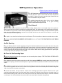
SRP Sparktimer Operation
(Cliquer ici pour version française)
The SRP Sparktimer allows 90 distinct frequencies to be used for
recording the pucks' path on the Air Table. The lower frequencies
are better for slow puck motion and the higher frequencies are
more convenient for fast puck motion.
The
available frequencies range from 10 Hz to 100 Hz. Unless
otherwise stated, the best frequency for any given recording
should be determined through trial runs.
Shock Hazard!
Since the latest model of Sparktimer is powered by low voltage adaptors, there is not enough current in the system to
allow for actual shocks if someone touches the recording paper sheet, the carbon paper or the metallic part of the pucks.
The sensation is very similar to static electricity discharges experienced when touching a charged doorknob or plastic
chair; the main difference being that recharge is fairly rapid and that a new spark will be ready to go at the rate
determined by the chosen frequency.
Each spark is very short-lived and lasts only a few milliseconds. This is what allows a dot to be recorded and not a line.
At all times, NO VOLTAGE OR CURRENT ARE POSSIBLE on the Air Table IF THE FOOTSWITCH IS NOT BEING
PRESSED.
Audible Sparking
If you can distinctly hear the sound of sparking coming from inside the Sparktimer, this may mean that one of the pucks
is NOT properly lying on or traveling OVER the carbon covered area, or that one chain does not reach the bottom of the
central tube in one of the pucks or that the protective sheet has not been removed from the carbon sheet, or that the
carbon coated side has not been placed facing up on the air table. When dots are being generated as the pucks glide
over the paper sheet, the sparking is barely audible.
No Trace On The Recording Paper
Remember that the trail of dots will never appear over the recording sheet of paper. THE TRACE WILL BE PRODUCED
UNDER THE PAPER SHEET.
If the Sparktimer seems to operate correctly but no trail of dots appears UNDER the recording paper sheet following the
passage of the puck(s), this means that the sparks are generated inside the Sparktimer and not on the surface of the Air
Table.
This condition is most likely to occur when only one puck needs to move for an experiment; the other puck being left to
lie out of the way against one side of the Air Table. This may allow the center of the un used puck to lie farther away than
1/8th of an inch from the carbon covered area.
To
correct this situation, fold one of the far corners of the recording paper sheet to expose a little the corner of the
underlying carbon paper sheet. Place the unused puck over that corner with the center lying over the carbon area. The
thicker folded recording paper under one side of the puck will kill the air cushion and allow the puck to remain motionless
over this spot. Your next try with the other puck should be successful (if the footswitch is depressed).
Holes
in the carbon sheet are also likely to develop where a puck is left to lay unmoving for some time while the
Sparktimer operates. It is suggested to be on the lookout for the development of such holes since they will eventually
grow wide enough to prevent proper sparking on the table. The operator only needs to displace slightly the stationary
puck once in a while to control this problem.
Become Familiar With The Sparktimer
The dot recorded by the puck hooked to the black lead will typically be slightly darker than those recorded by the puck
hooked to the red lead. This is normal and should not be perceived as a sign of wrong adjustment or defective
Sparktimer. This is due to the fundamental principle upon which the spark generated dots are produced. The units are
calibrated so that the slightly lighter dots produced by the red lead are sufficiently well marked to allow easy reading and
measurements.
DIGITAL SPARKTIMER 9 VDC OR 9 VAC
The
9 VDC (for units with Serial Numbers beginning with A3306-??-???? and lower) or 9 VAC (for units with Serial
Numbers beginning with A3309-??-???? or higher) Digital Sparktimer is provided with a CSA approved adapter and
allows 90 frequencies (from 10 Hz to 100 Hz) selectable with 2 push buttons located at the left of the digital display.
A
RESET BUTTON is conveniently located on the front panel to allow resetting of the unit, should the display and
behavior show that the unit has stopped operating. Remember, there is a microcontroler inside; which, just like any
computer, is subject to stop operating altogether when subjected to strong magnetic fields. This, however, will not occur
if the leads are properly connected to the Air Head and the pucks are being circulated over the carbon covered area of
the Air Table. It may happen though if the Footswitch is depressed while the leads are not connected or the pucks are
not lying over the carbon sheet.
The
unit is microcontroller driven and the frequencies are computed from the very stable 12 MHz frequency of the
microcontroller Crystal.
CAUTION :
Care must be taken not to depress the footswitch when only one of two Air Head cables (red or
black) is connected to the back of the Sparktimer or when only one puck is connected to the air head or when one
connected puck is lying outside the carbon sheet surface. When this condition occurs, the usual outcome generally will
be a freezing up of the microcontroller program, which can be remedied by resetting the unit. However, in extreme
conditions, such a condition may even result in burning out a protective component inside the unit, which would
require the unit to be serviced before it can be used again.
IMPORTANT WARNING
When
the SRP Air Table is installed permanently on a lab bench, it is critical that the AIR
COMPRESSOR be located away from the SPARKTIMER. The best set up involves locating the
compressor on the floor below the bench and the sparktimer on the bench close to the Air Table.
The reason is that the electric motor of the compressor generates a powerful magnetic field to which
the Sparktimer microcontroler driven main pc-board is very sensitive.
Close proximity between the two devices can cause the Sparktimer to malfunction or even blow a
protective part on the board that will require servicing.
If the installation is not permanent, and the sparktimer and compressor are mounted on a mobile cart,
we strongly suggest removing the sparktimer from the cart when installing the air table and placing it
close to the air table on the bench as far as possible from the cart, or to remove the compressor from
the cart to place it on the ground below the lab bench, again, as far as possible from the sparktimer.
A distance of about 60 cm (2 feet) is suggested.
Troubleshooting
DEBUGGING SEQUENCE
The user should become aware that most cases of "apparent" Sparktimer malfunction as the Air table and Sparktimer
are being set up for a new series of experiments may be due by a variety of causes, most of them involving other
components. Unfortunately, some of these apparent malfunctions may lead to "real" Sparktimer malfunction if the unit is
OVERTESTED before this external issue is identified and corrected.
At the beginning of each semester or whenever a new teacher or technical support person begins to use the system, it
is a good practice for this person to first read the user manual and/or discuss with a person who has already successfully
used it to become familiar with the possible problem sources.
When all possible conditions are well understood, there is seldom any problem with the Air able.
GENERAL MALFUNCTION CAUSES:
1- If the power adaptor is replaced with a local power adaptor, it must have a 9 VAC output with a 2.1mm plug with
1 Amp capacity VAC (for units with serial numbers beginning with A3309-??-???? or higher). (for units with serial
numbers beginning with A3306-??-???? and lower, a 9 VDC power adaptor is required). Capacity lower than 1
Amp (1000 mA) is insufficient to fully power the unit and may cause malfunction. Voltage higher than 9 Volts can
burn the rectifier components.
2-
Electric
3-
The
4-
If carbon sheets are purchased locally, it is CRITICAL to verify that they are electrically conductive. If
motors generate powerful magnetic field that are strong enough at close range to destabilize the
microcontroler on the pc board of the Sparktimer and can eventually burn the protective H11D1 optocoupler.
This is why it is recommended that the air compressor be placed on the floor under the lab bench (setting a safe
distance of about 60 cm between Sparktimer and Compressor).
Air Table should not be installed over a metallic surface since such material may contribute to transmit
transient Magnetic fields that may interfere.
not, the sparking will constantly occur on the safety gap inside the Sparktimer and NO TRACE can be
obtained on the air table. Overtesting the unit in this condition can lead to burning of the H11D1 and
possibly of other components. Most "carbon" sheets available in the open market contain no carbon
but are WAX BASED and DO NOT conduct electrical current.
ROUTINE VERIFICATION:
When setting up the Air Table for a new experiment, the following points must always be verified if the
Sparktimer doesn't seem to produce dots under the test sheet:
5- If the sound of sparking is heard coming from inside the Sparktimer, this may mean that
a) one of the pucks is NOT properly lying over or traveling OVER the carbon covered area,
b) or that the unused puck has been left long enough without moving so that it could have burned a hole too large
in the carbon sheet for the sparking to occur on the table.
c) or that one chain does not reach the bottom of the central tube in one of the pucks
d) or that the protective sheet has not been removed from the carbon sheet,
3) or that the carbon coated side has not been placed facing up on the air table.
When dots are being generated as the pucks glide over the paper sheet, the sparking is barely audible.
6- BOTH pucks must lie at all times above the surface covered by the carbon sheet for dots to be printed on the test
paper sheet located between the carbon sheet and the pucks.
7- If only one puck is required for a particular trace to be produced, the other puck must still remain on the air table
with its central electrode remaining above the carbon sheet. HOWEVER: if this unused puck Is left too long in the
same place, a larger and larger hole will be eaten up in the carbon sheet as the sparking proceeds, and after some
time the hole will become wide enough and resistive enough to prevent the sparking from making a trace with the
other puck. The sparking will then occur on the safety gap inside the Sparktimer enclosure. To prevent this condition,
it is suggested to be on the lookout for the development of such holes. The operator only needs to displace slightly
the stationary puck once in a while to control this problem.
NOTE that case number 7 just detailed is typically the main source of "apparent" malfunction of the Sparktimer after
a few good working runs.
8- When verifying conditions 5- to 7- does not solve the problem, then The Air Head connections must be verified.
Are the black and red Leads plugged into the Sparktimer? The latex tubes are translucent enough to allow seeing the
conducting chains inside. The user must then look closely to see if one chain has not been accidentally pulled down
and disconnected from the aluminum nozzle inside the tube close to the Air head.
9- Extensive OVERTESTING of the sparktimer when not properly connected to the air table so as to produce a test
trace under the paper sheet can lead to eventual burning of the H11D1 optocoupler. This is why IMMEDIATE
attention and verification of all previously described points must be made as soon as the sparking is HEARD coming
from INSIDE the Sparktimer enclosure and/or no trace appears under the test paper sheet that lies over the carbon
sheet.
When
all "apparent" malfunctions previously described are IMMEDIATELY investigated and corrected, the
Sparktimer will give years of service without any problem.
LAST RESORT SYSTEMATIC PROCEDURE
Note that it is normal to suspect the Sparktimer of malfunctioning whenever no sparking occurs on the air table as a new
experiment is being set up, BUT immediate OVERTESTING without normal sparking on the Air Table tends to overstress
the inner components and can often lead to real malfunction.
Other components on the Air Table can also (most of the time in fact) be the real cause of apparent malfunction. The
following procedure will allow identifying which component is the real source of the problem.
When visual inspection of all previously described points do not allow identifying and correcting a problem, here is the
quick procedure to identify which of the 5 following components is malfunctioning (Sparktimer, footpedal, Air Head,
Pucks, or Carbon sheet)
1- Turn the compressor off to diminish the ambiant noise. Disconnect the Air Head black and red leads from the
Sparktimer. Connect the footpedal, turn the unit On (the two digits showing the frequency will light up on the front panel
of the unit) and depress the foot pedal.
-- If the frequency sound is clearly heard coming from inside the Sparktimer, it means that the sparktimer is operating
correctly.
-- If no frequency sound is heard, it may be the footpedal malfunctioning. Verify if the footpedal plug is correctly
inserted. If so, then there is need to test the footpedal plug with an ohmmeter to see is it is conducting when the
footswitch is depressed. If the footpedal Is proved to work correctly, then the Sparktimer is definitely malfunctioning,
and further testing is useless. The Sparktimer (or footpedal) then needs to be repaired.
2- If step 1 confirms that the Sparktimer and footpedal are working, connect the Air Head black and red leads to the
Sparktimer (let the compressor turned Off). Disconnect both transparent plastic plugs from both pucks. And let the
chains hang loose on the surface of the Air table. Place some thick non-conducting material under the chains, for
example an exercise book or folder to isolate the chains from the underlying carbon sheet.
Place the chains very close
to one another (about one millimeter apart) and depress the footpedal. If the Air Head is ok, then sparks will be visible
between the chains as the sparking proceeds. This condition confirms that the Air Head, Sparktimer and footpedal are
working fine.
3- The next step is to visually look at the underside of the steel pucks. As the operator slides the side of a straight edge
ruler or the side of a pencil flat against the underside, he must be attentive to see if the central electrode is recessed too
far from the underside surface of the puck. If the electrode is recessed, then the distance from the carbon sheet may
have become to large to allow proper sparking.
Correct setting is to have the tip of the electrode flush with the underside
of the puck. It can be screwed in and out with a flat screwdriver inserted into the central tube of the puck.
4- If step 2- confirms that the Air Head is sound and step 3- confirms the central electrodes of both pucks are flush with
the underside of the pucks (remember that both chains must reach completely down inside the central puck tubes for
conductivity to be established), this means that the whole system is sound and working.
If sparking still does not occur on the air table when the Air Head is connected to the pucks and the footpedal is
depressed, it can then only be on account of a really conducting carbon sheet not to have been put on the air table.