1
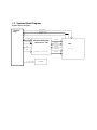
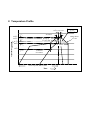
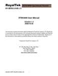
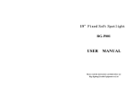
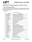
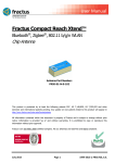
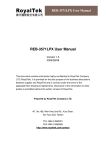
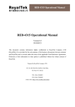
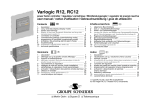
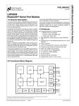
RTM-6000 User Manual Version 1.4 2009/04/14 This document contains information highly confidential to RoyalTek Company LTD (RoyalTek). It is provided for the sole purpose of the business discussions between supplier and RoyalTek and is covered under the terms of the applicable Non-Disclosure Agreements. Disclosure of this information to other parties is prohibited without the written consent of RoyalTek. Prepared by RoyalTek Company LTD. 4F, 188, Wen Hwa 2nd Rd., Kuei Shan. Tao Yuan 33377, Taiwan TEL: 886-3-3960001 FAX: 886-3-3960065 http://www.royaltek.com/contact 0. Revision Histories Rev 1.0 1.1 1.2 1.3 1.4 Release Date 2007/08/29 2007/10/24 2008/05/23 2008/10/30 2009/04/14 Change Description Initial Draft Increasing 8. temperature profile Change schematic Change RDS sensitivity Add Product applications Editor Amanda Lee Amanda Lee Linda Fan May Chen May Chen Content 1 2 3 4 5 6 7 8 Intruduction ............................................................................................................... 4 1.1 Product Features .......................................................................................... 4 1.2 Product Applications.................................................................................... 4 1.3 System Block Diagram ................................................................................ 5 Specification.............................................................................................................. 6 Reference schematic:................................................................................................. 8 Hardware Interface: ................................................................................................... 9 Recommend layout PAD: ........................................................................................ 11 Layout Note:............................................................................................................ 12 Mechanical Drawing ............................................................................................... 12 Temperature Profile ................................................................................................. 13 1 Intruduction RoyalTek RTM-6000 is the RDS-TMC demodulator module using Silicon Lab Si4703 chip and Silicon Lab C8051F331 MCU. RTM-6000 has a low power consumption and can operate at a low supply voltage. The module demodulates the RDS-TMC in FM band from 87.5MHz to 108MHz. The block data and status information are available via I²C bus. Then pass through C8051F331 (MCU) transmission CMOS level (+3.3V) to communicate with device. The smallest form factor and miniature design is the best choice to be embedded in a portable device like PDA, PND and navigation such as personal locators, speed camera detectors and vehicle locators. The module can be used on supporting navigation and traffic application. 1.1 Product Features Complete FM/RDS receiver module FM mixer for conversion of the US/Europe (87.5MHz to 108MHz) Auto search tuning, raster 100kHz Only one single power supply (DC+2.9 ~ 3.6V) Serial TTL interface High quality stereo audio output Ultra compact size : (L) 10 (+-0.2) * (W) 9.3 (+-0.2) * (H) 2 (+0.25, -0.1)mm 1.2 Product Applications Automotive navigation Personal positioning device and handheld, mobile navigation equipment In- vehicle device for RDS TMC usage 1.3 System Block Diagram System block diagram, FM_ANT AUDIO_R AUDIO_L OUTPUT PIN C2DAT C2CLK MICROCONTROLER C8051F331-GM TX SCLK SDIO TMC nINT nRST1 RX INTERFACE CONTROLER V_IN_3V3 POWER RCLK Si4703 2 Specification No Function Mechanical requirements 13 Weight 14 Dimension Specification ≦0.43 g 10mm±0.2mm(L) x 9.3mm±0.2mm(W) x 2mm+0.25-0.10mm(H) TMC/RDS receiver 1 Chipset 2 Frequency 3 sensitivity Silicon Lab Si4703-GM 87.5~108MHz. US/Europe 2.5 μVEMF typ. (S+N)/N=26dB FMOD = 1 kHz, 75 μs de-emphasis MONO = 1, and L = R unless noted otherwise. Δf = 22.5 kHz. BAF = 300 Hz to 15 kHz, A-weighted. 12 μVEMF min. Δf = 2 kHz, RDS BLER < 5% RDSPRF = 1 RDS sensitivity Antenna Input 4 Matching Interface 5 Output 6 Baud rate 7 I/O Pin Power consumption 8 Vcc 9 Current Audio Function Audio output 10 voltage Audio output 11 resistance 12 AF THD 13 Audio Mono S/N 50 ohm TTL +3.3V serial interface 38400bps 12pin I/O pin DC +2.9~3.6V Current ≦35mA Maximum @DC +3.3V Min. Typ. Max. Unit. Note. 72 80 90 mVRMS 10 -- -- k ohms -- 0.1 0.5 % 55 63 -- dB FMOD = 1 kHz, 75 μs de-emphasis MONO = 1, and L = R 14 Audio Stereo S/N -- 58 -- dB Environment 10 Environment Building in Navigation Cube 11 Operating temperature -20 °C to +85 °C 12 13 Storage Temperature Humidity -40 °C to +100°C ≦95% unless noted otherwise. Δf = 22.5 kHz. BAF = 300 Hz to 15 kHz, A-weighted. VEMF = 1 mV, fRF = 87.5 to 108 MHz. Δf = 22.5 kHz. 3 Reference schematic: FM-ANTEENA INPUT R21 10(1%) 0402 4~5mil ESD4 EV05C65R40G 1 C32 C33 12PF/50V;J 12PF/50V;J L8 ESD0402 390nH(Chilisin) 0603,CL160808T-R39K-N Audio_R V_3V3 V_3V3 C1 U1 RTM-6000 50 ohm trace1 2 3 4 5 RX Serial Data IN Serial Data OUT Audio_L C2 TX C5 open C6 open 10 GN FM_ANT 9 AUDIO_R GN 8 AUDIO_L 7 N.C. V_IN_3V3 6 R TX N.C. N.C. R1 10K N.C. R2 10K 2.2uF~10uF 11 12 AUDIO_R AUDIO_L V_3V3 L1 BEAD 0805-1Kohm 25% 1 + C4 0.1uF C3 22~47uF 2 2.2uF~10uF (1)GND GND provides the ground for RTM-6000 Module. (2)Power: Connect V_IN_3V3 pin to DC 2.9~3.6V.The power supply must add Bead and bypassing capacitor(22~47uF).It can reduce the Noise from power supply and increase power stability. (3)TX This is the main transmitting channel and is used to output user application software. (4) RX This is the main receiver channel and is used to receive software commands to user application software. (5)AUDIO_L/R The two pin contains the Audio of the left/right channel directly out of the Si4703. (6)FM_ANT This pin is FM Antenna input pin. It is suggested to use 50 ohm trace from FM-ANT pin to FM antenna connector. 4 Hardware Interface: Pin definition: NO. Name P1 FM_ANT P2 GND P3 N.C. I/O Descriptions I FM antenna input ~ Ground ~ Test Pin P4 RX I P5 TX O P6 N.C. P7 V_IN_3V P8 AUDIO_L P9 AUDIO_R P10 GND P11 N.C. P12 N.C. (1)GND ~ ~ O O ~ ~ ~ Characteristics FM antenna input(50ohm trace ) Common Ground None Connector 2.0V≦VIH≦3.3V Serial Data in 0V≦VIL≦0.8V 2.5V≦VOH≦3.3V Serial Data out 0V≦VOL≦0.6V Test Pin None Connector System power input DC:2.9~3.6V.Current ≦35mA typ.@+3.3V Left audio output. Left audio output Right audio output Right audio output Ground Common Ground Test Pin None Connector Test Pin None Connector GND provides the ground for RTM-6000 Module. (2)Power: Connect V_IN_3V3 pin to DC 2.9~3.6V @3.3V TYP..The power supply must add Bead and bypassing capacitor (10~33uF).It can reduce the Noise from power supply and increase power stability. (3)TX This is the main transmitting channel and is used to output user application software. (4) RX This is the main receiver channel and is used to receive software commands to user application software. (5)AUDIO_L/R The two pin contain the Audio of the left/right channel directly out of the Si4703-GM (6)FM_ANT This pin is FM Antenna input pin. It is suggested to use 50 ohm trace from FM-ANT pin to FM antenna connector. (7)No connection pin These pin (C2CLK, C2DAT) are used for MCU (C8051F331) FIRMWARE UPDATE. 5 Recommend layout PAD: 6 Layout Note: (1) The trace connected to FM_IN should be 50 ohm. (2) It is recommended to add Bead and bypass capacitor above 10~33uF to reduce power noise. (3) The system’s EMI or noise is recommended to reduce first which efficiently boost TMC performance. (4) Please refer to the recommend pad for connecting well. 7 Mechanical Drawing 8 Temperature Profile 260oC,10sec max 260oC 245oC 20~40sec TP Ramp-down 6oC/sec Ramp-up 3oC/sec max TL o 217 C 200oC 60~150sec Tsmax Temperature 150oC Tsmin Critical Zone TL to TP Ts Pretest 60~180sec T25oC to peak, 480 sec max Time RTM-6000 Lead-Free Standard Reflow Profile