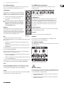
1
User Manual
EUROPORT EPA900
Ultra-Compact 900-Watt 8-Channel Portable PA System with
Digital Effects and FBQ Feedback Detection
2
EUROPORT EPA900 User Manual
Table of Contents
Thank you........................................................................ 2
Important Safety Instructions....................................... 3
Legal Disclaimer.............................................................. 3
Limited Warranty............................................................ 3
1. Before You Get Started.............................................. 5
1.1 Shipment................................................................................. 5
1.2 Initial operation.................................................................... 5
1.3 Online registration.............................................................. 5
2. Installation.................................................................. 5
2.1 Setup Preparations.............................................................. 5
2.2 Setup........................................................................................ 6
3. Control Elements and Connections.......................... 6
3.1 Mono Channels (1-4)........................................................... 6
3.1.1 Microphone/Line Inputs.............................................. 6
3.2 Stereo Channels (5/6-7/8).................................................. 6
3.2.1 Line Inputs....................................................................... 6
3.3 Channel Strips....................................................................... 7
3.4 Additional Connections.................................................... 7
3.5 SPEAKER OUTPUTS............................................................. 7
3.6 Graphic Equalizer................................................................. 8
3.7 Effects Unit............................................................................. 8
3.8 Main Power Section............................................................ 8
3.9 Power Supply and Serial Number.................................. 8
4. Applications.............................................................. 10
5. Specifications............................................................ 11
6. Effects Table.............................................................. 12
Thank you
Thank you for purchasing the EUROPORT EPA900. The EPA900 is a portable,
ultra-compact powered mixer/loudspeaker combination with enormous power,
unbelievable sound, and an extremely low weight. The mixer unit has 8 input
channels (4 mono and 2 stereo channels), an internal 24-bit studio-quality
effects processor, and a 7-band graphic equalizer with FBQ feedback detection.
All channels have ultra-high precision 2-band EQs and CLIP LEDs for total control.
At 900 Watts, the high-performance power amp is properly sized, and with
the 2 supplied loudspeakers a microphone, including cable, you can get going
right away!
With the EPA900, you can quickly and easily master any sound situation.
We at BEHRINGER hope you enjoy your new acquisition.
3
EUROPORT EPA900 User Manual
Important Safety
Instructions
Terminals marked with this symbol carry
electrical current of sufficient magnitude
to constitute risk of electric shock. Use only
high-quality commercially-available speaker cables with
¼" TS plugs pre-installed. All other installation or
modification should be performed only by
qualified personnel.
This symbol, wherever it appears,
alerts you to the presence of uninsulated
dangerous voltage inside the
enclosure - voltage that may be sufficient to constitute a
risk of shock.
This symbol, wherever it appears,
alerts you to important operating and
maintenance instructions in the
accompanying literature. Please read the manual.
Caution
To reduce the risk of electric shock, do
not remove the top cover (or the rear
section). No user serviceable parts inside. Refer servicing
to qualified personnel.
Caution
To reduce the risk of fire or electric shock,
do not expose this appliance to rain and
moisture. The apparatus shall not be exposed to dripping
or splashing liquids and no objects filled with liquids, such
as vases, shall be placed on the apparatus.
9. Do not defeat the safety purpose of the polarized
or grounding-type plug. A polarized plug has two blades
with one wider than the other. A grounding-type plug
has two blades and a third grounding prong. The wide
blade or the third prong are provided for your safety. If the
provided plug does not fit into your outlet, consult an
electrician for replacement of the obsolete outlet.
10. Protect the power cord from being walked on or
pinched particularly at plugs, convenience receptacles,
and the point where they exit from the apparatus.
11. Use only attachments/accessories specified by
the manufacturer.
12. Use only with the
cart, stand, tripod, bracket,
or table specified by the
manufacturer, or sold with
the apparatus. When a cart
is used, use caution when
moving the cart/apparatus
combination to avoid
injury from tip-over.
13. Unplug this apparatus during lightning storms or
when unused for long periods of time.
14. Refer all servicing to qualified service personnel.
Servicing is required when the apparatus has been
damaged in any way, such as power supply cord or plug
is damaged, liquid has been spilled or objects have fallen
into the apparatus, the apparatus has been exposed
to rain or moisture, does not operate normally, or has
been dropped.
15. The apparatus shall be connected to a MAINS socket
outlet with a protective earthing connection.
16. Where the MAINS plug or an appliance coupler is
used as the disconnect device, the disconnect device shall
remain readily operable.
Caution
These service instructions are for use
by qualified service personnel only.
To reduce the risk of electric shock do not perform any
servicing other than that contained in the operation
instructions. Repairs have to be performed by qualified
service personnel.
1. Read these instructions.
2. Keep these instructions.
3. Heed all warnings.
4. Follow all instructions.
5. Do not use this apparatus near water.
6. Clean only with dry cloth.
7. Do not block any ventilation openings. Install in
accordance with the manufacturer’s instructions.
8. Do not install near any heat sources such as
radiators, heat registers, stoves, or other apparatus
(including amplifiers) that produce heat.
Limited Warranty
Limit
§ 1 Warranty
(1) This limited warranty is valid only if you purchased
the product from a BEHRINGER authorized dealer in the
country of purchase. A list of authorized dealers can be
found on BEHRINGER’s website behringer.com under
“Where to Buy“, or you can contact the BEHRINGER office
closest to you.
(2) MUSIC Group* warrants the mechanical and
electronic components of this product to be free of defects
in material and workmanship if used under normal
operating conditions for a period of one (1) year from
the original date of purchase (see the Limited Warranty
terms in § 4 below), unless a longer minimum warranty
period is mandated by applicable local laws. If the product
shows any defects within the specified warranty period
and that defect is not excluded under § 4, MUSIC Group
shall, at its discretion, either replace or repair the product
using suitable new or reconditioned product or parts.
In case MUSIC Group decides to replace the entire product,
this limited warranty shall apply to the replacement
product for the remaining initial warranty period, i.e.,
one (1) year (or otherwise applicable minimum warranty
period) from the date of purchase of the original product.
(3) Upon validation of the warranty claim, the repaired
or replacement product will be returned to the user freight
prepaid by MUSIC Group.
(4) Warranty claims other than those indicated above
are expressly excluded.
PLEASE RETAIN YOUR SALES RECEIPT. IT IS YOUR PROOF
OF PURCHASE COVERING YOUR LIMITED WARRANTY.
THIS LIMITED WARRANTY IS VOID WITHOUT SUCH PROOF
OF PURCHASE.
§ 2 Online registration
Please do remember to register your new BEHRINGER
equipment right after your purchase at behringer.com
under “Support” and kindly read the terms and conditions
of our limited warranty carefully. Registering your
purchase and equipment with us helps us process
your repair claims quicker and more efficiently.
Thank you for your cooperation!
§ 3 Return materials authorization
Legal Disclaimer
Technical specifications and appearance are subject to change without
notice. The information contained herein is correct at the time of printing.
All trademarks are the property of their respective owners. MUSIC Group
accepts no liability for any loss which may be suffered by any person
who relies either wholly or in part upon any description, photograph or
statement contained herein. Colors and specifications may vary slightly from
product. BEHRINGER products are sold through authorized dealers only.
Distributors and dealers are not agents of MUSIC Group and have absolutely
no authority to bind MUSIC Group by any express or implied undertaking
or representation. This manual is copyrighted. No part of this manual may
be reproduced or transmitted in any form or by any means, electronic or
mechanical, including photocopying and recording of any kind, for any
purpose, without the express written permission of Red Chip Company Ltd.
ALL RIGHTS RESERVED.
© 2010 Red Chip Company Ltd.
Trident Chambers, Wickhams Cay, P.O. Box 146,
Road Town, Tortola, British Virgin Islands
(1) To obtain warranty service, please contact the
retailer from whom the equipment was purchased.
Should your BEHRINGER dealer not be located in your
vicinity, you may contact the BEHRINGER distributor for
your country listed under “Support” at behringer.com.
If your country is not listed, please check if your problem
can be dealt with by our “Online Support” which may
also be found under “Support” at behringer.com.
Alternatively, please submit an online warranty claim at
behringer.com BEFORE returning the product. All inquiries
must be accompanied by a description of the problem
and the serial number of the product. After verifying
the product’s warranty eligibility with the original sales
receipt, MUSIC Group will then issue a Return Materials
Authorization (“RMA”) number.
Lega
4
EUROPORT EPA900 User Manual
(2) Subsequently, the product must be returned in
its original shipping carton, together with the return
authorization number to the address indicated by
MUSIC Group.
(3) Shipments without freight prepaid will not
be accepted.
§ 4 Warranty Exclusions
(1) This limited warranty does not cover consumable
parts including, but not limited to, fuses and batteries.
Where applicable, MUSIC Group warrants the valves or
meters contained in the product to be free from defects in
material and workmanship for a period of ninety (90) days
from date of purchase.
(2) This limited warranty does not cover the product
if it has been electronically or mechanically modified
in any way. If the product needs to be modified or
adapted in order to comply with applicable technical
or safety standards on a national or local level, in any
country which is not the country for which the product
was originally developed and manufactured, this
modification/adaptation shall not be considered a defect
in materials or workmanship. This limited warranty does
not cover any such modification/adaptation, regardless
of whether it was carried out properly or not. Under the
terms of this limited warranty, MUSIC Group shall not
be held responsible for any cost resulting from such a
modification/adaptation.
(3) This limited warranty covers only the product
hardware. It does not cover technical assistance for
hardware or software usage and it does not cover
any software products whether or not contained in
the product. Any such software is provided “AS IS”
unless expressly provided for in any enclosed software
limited warranty.
(4) This limited warranty is invalid if the factoryapplied serial number has been altered or removed from
the product.
(5) Free inspections and maintenance/repair work
are expressly excluded from this limited warranty, in
particular, if caused by improper handling of the product
by the user. This also applies to defects caused by normal
wear and tear, in particular, of faders, crossfaders,
potentiometers, keys/buttons, guitar strings, illuminants
and similar parts.
(6) Damage/defects caused by the following conditions
are not covered by this limited warranty:
• improper handling, neglect or failure to operate the
unit in compliance with the instructions given in
BEHRINGER user or service manuals;
• connection or operation of the unit in any way
that does not comply with the technical or safety
regulations applicable in the country where the
product is used;
• damage/defects caused by acts of God/Nature
(accident, fire, flood, etc) or any other condition that
is beyond the control of MUSIC Group.
(7) Any repair or opening of the unit carried out by
unauthorized personnel (user included) will void the
limited warranty.
(8) If an inspection of the product by MUSIC Group
shows that the defect in question is not covered by the
limited warranty, the inspection costs are payable by
the customer.
(9) Products which do not meet the terms of this
limited warranty will be repaired exclusively at the buyer’s
expense. MUSIC Group or its authorized service center will
inform the buyer of any such circumstance. If the buyer
fails to submit a written repair order within 6 weeks after
notification, MUSIC Group will return the unit C.O.D. with
a separate invoice for freight and packing. Such costs will
also be invoiced separately when the buyer has sent in a
written repair order.
(10) Authorized BEHRINGER dealers do not sell new
products directly in online auctions. Purchases made
through an online auction are on a “buyer beware” basis.
Online auction confirmations or sales receipts are not
accepted for warranty verification and MUSIC Group will
not repair or replace any product purchased through an
online auction.
§ 5 Warranty transferability
This limited warranty is extended exclusively to the
original buyer (customer of authorized retail dealer) and
is not transferable to anyone who may subsequently
purchase this product. No other person (retail dealer, etc.)
shall be entitled to give any warranty promise on behalf
of MUSIC Group.
§ 6 Claim for damage
Subject only to the operation of mandatory applicable
local laws, MUSIC Group shall have no liability to the buyer
under this warranty for any consequential or indirect
loss or damage of any kind. In no event shall the liability
of MUSIC Group under this limited warranty exceed the
invoiced value of the product.
§ 7 Limitation of liability
This limited warranty is the complete and exclusive
warranty between you and MUSIC Group. It supersedes
all other written or oral communications related to this
product. MUSIC Group provides no other warranties for
this product.
§ 8 Other warranty rights and
national law
(1) This limited warranty does not exclude or limit the
buyer’s statutory rights as a consumer in any way.
(2) The limited warranty regulations mentioned herein
are applicable unless they constitute an infringement of
applicable mandatory local laws.
(3) This warranty does not detract from the seller’s
obligations in regard to any lack of conformity of the
product and any hidden defect.
§ 9 Amendment
Warranty service conditions are subject to change without
notice. For the latest warranty terms and conditions
and additional information regarding MUSIC Group’s
limited warranty, please see complete details online at
behringer.com.
* MUSIC Group Macao Commercial Offshore Limited of
Rue de Pequim No. 202-A, Macau Finance Centre 9/J, Macau,
including all MUSIC Group companies
5
EUROPORT EPA900 User Manual
1. Before You Get Started
1.3 Online registration
1.1 Shipment
Please register your new BEHRINGER equipment right after your purchase
by visiting http://behringer.com and read the terms and conditions of our
warranty carefully.
Your EPA900 was carefully packed at the factory, and the packaging was
designed to protect the unit from rough handling. Nevertheless, we recommend
that you carefully examine the packaging and its contents for any signs of
physical damage that may have occurred during transit.
◊ If the unit is damaged, please do NOT return it to BEHRINGER.
Instead, notify your dealer and the shipping company immediately.
Otherwise, claims for damage or replacement may not be honored.
◊ Always use the original packing carton to prevent damage during
storage or transport.
◊ Make sure that no children are left unsupervised with the unit or
its packaging.
Should your BEHRINGER product malfunction, it is our intention to have it
repaired as quickly as possible. To arrange for warranty service, please contact
the BEHRINGER retailer from whom the equipment was purchased. Should your
BEHRINGER dealer not be located in your vicinity, you may directly contact
one of our subsidiaries. Corresponding contact information is included in the
original equipment packaging (Global Contact Information/European Contact
Information). Should your country not be listed, please contact the distributor
nearest you. A list of distributors can be found in the support area of our website
(http://behringer.com).
Registering your purchase and equipment with us helps us process your repair
claims more quickly and efficiently.
◊ Please ensure proper disposal of all packing materials.
1.2 Initial operation
Be sure that there is enough space around the unit for cooling. To avoid
overheating, please do not place the EPA900 near radiators and other equipment
emanating heat.
◊ Blown fuses must be replaced by fuses of the same type and rating!
Please refer to the “TECHNICAL SPECIFICATIONS” section for the correct
rating. To avoid an electric shock, turn off and unplug the unit before
replacing the fuse. For more information, please see Chapter 3.8
and Figure 3.9.
Thank you for your cooperation!
2. Installation
The EPA900 mobile PA system consists of two loudspeakers and a powered mixer
that easily join into a portable, wheeled unit for easy transportation. In the
following sections, you will find out how to set up and start up the PA system.
2.1 Setup preparations
Follow the instructions to ensure straightforward and reliable operation of
the EPA900.
The mains connection is made using the enclosed power cord and a standard IEC
receptacle. It meets all of the international safety certification requirements.
1. Open the upper latch.
◊ Before connecting the unit to the mains, please check that it is set to
2. Open the latches on the sides of the PA unit by pressing and then
lifting them.
the correct supply voltage.
◊ You have to use another fuse if you set the unit to another supply
voltage. The correct value is specified in Chapter “Specifications”.
3. With one hand, grab hold of the recessed handle above the latch on the side
of the loudspeaker and hold the upper handle with the other hand.
Then, carefully remove the loudspeaker sideways from the mixer.
◊ Please make sure that all units have a proper ground connection.
(1)
For your own safety, never remove or disable the ground
conductor from the unit or of the AC power cord. The unit shall
always be connected to the mains socket outlet with a protective
earthing connection.
◊ Please ensure that only qualified people install and operate the
mixing console. During installation and operation, the user must have
sufficient electrical contact to earth, otherwise electrostatic discharges
might affect the operation of the unit.
◊ The sound quality may diminish within the range of powerful
(3)
(2)
broadcasting stations and high-frequency sources. Increase the
distance between the transmitter and the device and use shielded
cables for all connections.
Fig. 2.1: EPA900 setup
◊ Be careful to prevent the loudspeaker from accidentally falling on
your foot.
4. Repeat Step 3 for the second loudspeaker.
5. Place the mixer in an upright position.
◊ To assemble the PA unit for transportation, perform the steps in the
reverse order.
6
EUROPORT EPA900 User Manual
2.2 Setup
3.1 Mono Channels (1-4)
1. Separate the three pieces of the PA unit as described in Chapter 2.1.
Channels 1-4 are designed as mono channels and are used to connect
microphones or mono line-level sources. The connectors are balanced to
ensure high interference resistance. If possible, you should use balanced cable
connectors to profit from the advantages of this type of connection.
2. Place the mixing console and loudspeakers in the required positions in
the venue.
◊ Use of the optional loudspeaker stands ensures a wider, more even
dispersion of sound.
3. Using the supplied cables, connect the loudspeakers to the rear
loudspeaker outputs.
!!
Caution
ONLY connect the EPA900’s loudspeakers, never other equipment, via the rear
loudspeaker connectors. Otherwise, your equipment could get damaged.
4. Connect instruments, microphones, and additional equipment via the
remaining connectors on the mixer (see Chapter 4).
5. If you have an active subwoofer available (not included), connect it to the
SUB OUT socket.
6. Ensure that the two volume control knobs in the MAIN LEVEL CONTROL have
been turned counterclockwise as far as possible.
7. Use the IEC power cord to connect the mixer’s power inlet to an AC outlet.
8. Turn on the mixer.
9. Make the desired settings.
3.1.1 Microphone/Line Inputs
MIC
You can connect either dynamic
microphones or condenser microphones to
the MIC connector using XLR plugs.
LINE IN
Via the LINE IN connector, you can
connect instruments (e.g., keyboards,
electric guitars) or other line-level
sources (e.g., CD player, external
mixers, notebook sound card).
The ¼" jack accepts both balanced and
unbalanced connectors.
Fig. 3.1: Mono channel connectors
PAD
With the PAD switch, you can weaken loud input signals by 20 dB. Use this
function if the CLIP LED is lit up and the level cannot be reduced any further using
the LEVEL control.
!!
PHANTOM
We would like to point out that high volume levels could damage your hearing.
Always make sure that the appropriate volume is set.
3.2 Stereo Channels (5/6-7/8)
Caution
3. Control Elements and
Connections
The EPA900 mixer is equipped with 4 mono and 2 stereo inputs and an additional
AUX input. The input signals are internally distributed to a stereo bus. It is also
possible to use its channels separately (mono), such as when used for FOH/PA and
stage. Depending on the requirements, one stereo or two independent mono
sounds can be run. An internal effect can be used as an AUX effect from each
channel. The 7-band graphic equalizer is used to process the stereo bus or the
two mono paths.
With the PHANTOM switch, you can activate the phantom power supply for all
microphone channels. Use the supply for condenser microphones.
Channels 5/6-7/8 are designed as stereo channels and are used to connect stereo
line-level sources.
3.2.1 Line Inputs
LEFT (L) / RIGHT (R)
Via these connectors, you can connect stereo line-level
sources (e.g., keyboard, CD player, external mixers,
notebook sound card). Either the cinch jacks or the ¼" jacks
can be used, but not both at the same time.
VOICE CANCELLER (Channel 7/8)
The VOICE CANCELLER function enables voice to be filtered
out of stereo signals. This function is useful for karaoke
applications with a player (CD/MP3 player, etc.).
Fig. 3.2: Stereo
channel connectors
7
EUROPORT EPA900 User Manual
3.3 Channel strips
3.4 Additional connections
Each channel strip is equipped with an equalizer section, an effects control,
and one control each for signal routing and volume control.
The EPA900 is equipped with additional inputs and outputs as well as a
footswitch connector.
TREBLE/BASS
The equalizer section comprises these two controls. With the
TREBLE control, you can modify the high frequencies, and with
the BASS control the low frequencies. Rotate the control knob:
Fig. 3.4: Connectors for additional devices
• clockwise to boost the frequency range by max. 15 dB.
STEREO AUX IN
• counterclockwise to cut the frequency range by
The STEREO AUX IN sockets are designed as separate ¼" jacks and as a stereo
minijack. You can connect additional devices with adjustable line levels
(e.g., other mixers, MD player) here. The signal is sent directly to the output
busses, with no further adjustment possible. Use either the minijack or the
two ¼" jacks, not both types at the same time. For mono sources, use the
LEFT connector.
max. 15 dB.
◊ If you use the equalizer section to boost frequencies,
the signal level of the channel increases. If the CLIP
LED lights up, you need to reduce the level using the
corresponding LEVEL control.
EFFECTS
EFFECTS FOOTSW
With the EFFECTS control, you can specify the portion of the
channel signal to be routed to the effects unit. The further
clockwise you turn the control knob, the greater the effect that
is applied to the signal. Turning the knob counterclockwise as
far as possible results in a signal with no effects.
The EFFECTS FOOTSW socket is used to connect a footswitch. You can switch the
effect on and off with the foot switch.
BAL
SUB OUT
Fig. 3.3: Channel
strip for a
mono channel
You can connect an active subwoofer to the SUB OUT socket.
TAPE OUT
Use the BAL control of the mono channels to adjust the
position of the signal within the stereo image (left/right) or for both mono paths.
Turn the control:
You can connect a 2-track recorder (DAT, MD, etc.) to the TAPE OUT sockets.
The two TAPE OUTs carry the output bus signals.
• completely to the left to hear the signal only on the left side, that is the
3.5 Speaker outputs
LEFT/MAIN path.
• completely to the right to hear the signal only on the right side, that is the
The SPEAKER OUTPUTS connectors on the back of the unit are used to connect the
supplied loudspeakers.
RIGHT/MAIN path.
Positions between these settings will result in a proportionate signal allocation
between LEFT/MAIN and RIGHT/MAIN.
The BAL control determines the levels of a stereo source’s left and right input
signals in relation to each other. Turn the control:
• completely to the left to hear only the left signal component of the stereo
source on the LEFT/MAIN path.
• completely to the right to hear only the right signal component of the stereo
source on the RIGHT/MAIN path.
Positions between these settings will result in a proportionate signal allocation
of the left/right signal component between LEFT/MAIN and RIGHT/MAIN.
Fig. 3.5: Powered connectors for passive loudspeakers
CLIP
When lit up, the CLIP LED indicates that the corresponding channel is being
overdriven. If this LED lights up regularly, you need to reduce the level of the
respective channel using the LEVEL control and/or the PAD switch.
LEVEL
The LEVEL control is used to set the volume of the channel signal. If the CLIP LED
is lit up, the level has to be reduced using this control.
!!
Caution
The outputs are powered outputs, which put out a strong, amplified signal (not a
low-level LINE signal!). For this reason, only PASSIVE loudspeaker systems can be
connected. Other devices could get damaged.
• If loudspeakers with an impedance of 4 Ω are used, the two outputs have a
maximum power of 900 W.
• If loudspeakers with an impedance of 8 Ω are used, the two outputs have a
maximum power of 800 W.
8
EUROPORT EPA900 User Manual
3.6 Graphic equalizer
PROGRAM (PUSH)
The EPA900 is equipped with a 7-band graphic equalizer, which enables you to
adapt the sound to the room conditions and your own ideas for the sound.
The equalizer always processes the LEFT/MAIN and RIGHT/MAIN bus equally.
You can turn the PROGRAM control knob to select an effects preset. Then press
the knob to activate the selected effect.
EFFECTS (LEVEL)
The EFFECTS (LEVEL) control is used to adjust the effects signal volume.
3.8 Main Power Section
The operating volume of the sound system is set via the main power section
(MAIN LEVEL CONTROL).
Fig. 3.6: Graphic equalizer section
EQ ON
You can activate the equalizer using the EQ ON switch.
FBQ ON
Using the FBQ ON switch, you can activate the feedback detection circuit.
This function only has an effect if the equalizer is active. For every frequency
that causes feedback, the corresponding LED on a slide control lights up.
Lowering the displayed frequency minimizes feedback.
3.7 Effects unit
The EPA900 is equipped with an internal stereo effects processor, which offers
100 different standard effects, including reverb, chorus, flanger, and echo, as well
as various multieffects. It is permanently integrated into the mixer as a
Send/Return effect; i.e., an adjustable signal portion can be routed to the effects
unit from every input channel. The selected effect is applied to the signal
portions of the channels, and the signals are then mixed with the direct signals
via the stereo bus.
Fig. 3.8: Control elements in the main power section
LEFT/MAIN and RIGHT/MAIN
The two controls are used to adjust the volume of the corresponding
loudspeaker outputs.
MODE
With the MODE switch, the power amplifier section can be switched to stereo
or mono mode. Depending on the setting, the limiter, which provides overdrive
protection for the system, works in coupled stereo or independent mono mode.
◊ Always remember to set the switch according to the given application
to avoid incorrect limiter behavior!
3.9 Power supply and serial number
FUSE HOLDER/IEC SOCKET
Connection to an AC power supply is made via an IEC socket. It complies with
applicable safety regulations. A suitable AC power cord is included. Replace the
fuse with a fuse of the same type.
Fig. 3.7: Internal 24-bit multieffects unit
CLIP/SIG
The CLIP and SIG LEDs provide information on the signal level on the effects unit.
• When continuously lit up, the CLIP LED indicates a signal overdrive. In this
case, the effects unit input level should be reduced through lowering of the
Send level using the EFFECTS controls for the input channels.
• The SIG LED signalizes that the effects processor is receiving a signal and is
working. If the LED is not lit up, the input signal is too weak.
Fig. 3.9: Power supply and fuse
◊ To avoid an electric shock, turn off and unplug the unit before replacing
the fuse.
9
EUROPORT EPA900 User Manual
POWER Switch
Use the POWER switch to start up the unit. The POWER switch should be in the
“Off” position when you connect the unit to the AC power supply.
To disconnect the unit from the power supply, pull out the power plug.
When starting up the unit, ensure that the power plug is easily accessible.
◊ Please note: Switching the POWER switch off does not completely
disconnect the unit from the power supply. For this reason, you should
unplug the power cord if the unit is not going to be used for a long
period of time.
VOLTAGE SELECTOR
The VOLTAGE SELECTOR switch lets you set the correct operating voltage.
◊ Before connecting the unit to the mains, please check that it is set to
the correct supply voltage.
◊ You have to use another fuse if you set the unit to another supply
voltage. The correct value is specified in Chapter “Specifications”.
SERIAL NUMBER
The serial number can be found on the back of the mixer. It is needed for
online registration.
10
EUROPORT EPA900 User Manual
4. Applications
The EPA900 can be used for simple sound tasks, e.g., amplification of the
presenter’s voice, playback sound, or karaoke applications, as well as for
demanding tasks such as band amplification or stage monitor sound. A typical
example of use as a sound system for music with live instruments and players is
given below.
ULTRAVOICE XM8500
In 1
In 2
Speaker Output
Lef/Main
In 5/6
In 3
Drum Computer
GMX212
In 7/8
Stereo
AUX In
EPA900
CD player
Electric Guitar
Fig. 4.1: Sound example
Keyboard
11
EUROPORT EPA900 User Manual
5. Specifications
Inputs 1-4
Effects
Type
4 x XLR, electronically balanced,
4 x ¼" TRS jack, electronically balanced
Impedance
approx. 2.2 kΩ , balanced,
approx. 1.1 kΩ , unbalanced
Input sensitivity
-21 dBu @ PAD/OFF
Max. gain
+30 dB to +10 dB
Phantom power supply
+48 V
Signal-to-noise ratio
-90 dB, A-weighted
Channel separation
70 dB
Inputs 5-8
Converter
24-bit delta-sigma
Sampling frequency
40 kHz
Display
2-digit, 7-segment
Type
7-band
EQ
Loudspeaker Outputs
Type
2 x ¼" TS jack
Load impedance
8Ω
Output Power
Type
4 x ¼" TS jack, unbalanced
4 x RCA phono jack, unbalanced
Impedance
approx. 20 kΩ , unbalanced
Input sensitivity
-15 dBu
Max. gain
+20 dB
Frequency response
50 Hz to 44 kHz, ± 3 dB
Signal-to-noise ratio
-85 dB, A-weighted
Distortion (THD + N)
0.32% @ 1 W
Stereo Aux In
RMS @ 1% THD (sine signal) 8 Ω 2 x 360 W; 4 Ω 2 x 400 W
Peak power
8 Ω 2 x 400 W; 4 Ω 2 x 450 W
System Specifications
Power Supply
Type
1 x ¼" TS jack, unbalanced
1 x stereo minijack, unbalanced
Impedance
approx. 100 kΩ , unbalanced
Input sensitivity
-8 dBu
Signal-to-noise ratio
-90 dB, A-weighted
Power consumption
1,000 W
Fuse
T 10 A H 250 V (100 –120 V~, 50/60 Hz)
T 10 A H 250 V (220 –240 V~, 50/60 Hz)
Dimensions/Weight
Dimensions (H x W x D)
approx. 26.0 x 13.9 x 34.8"
approx. 660 x 354 x 883 mm
Weight
approx. 82.5 lbs / 37.5 kg
Tape Out
Type
2 x cinch jack, unbalanced
Impedance
approx. 1 kΩ
Max. output level
+17 dBu, unbalanced
Channel separation
> 70 dB
Sub Out
Type
1 x ¼" stereo jack, unbalanced
Impedance
approx. 1 kΩ
Max. output level
+ 21 dBu, unbalanced
Channel EQ
BASS
±15 dB @ 80 Hz
TREBLE
±15 dB @ 27 kHz
BEHRINGER is constantly striving to manintain the highest professional standards. As a result of these efforts,
modifications may be made from time to time to existing products without prior notice. Specifications and
appearance may differ from those listed or liiustrated.
12
EUROPORT EPA900 User Manual
6. Effects Table
EFFECT PRESETS
No.
00
01
02
03
04
05
06
07
08
09
10
11
12
13
14
15
16
17
18
19
20
21
22
23
24
25
26
27
28
29
30
31
32
33
34
35
36
37
38
39
40
41
42
43
44
45
46
47
48
49
EFFECT
HALL 00-09
SMALL HALL 1
SMALL HALL 2
SMALL HALL 3
MID HALL 1
MID HALL 2
MID HALL 3
BIG HALL 1
BIG HALL 2
BIG HALL 3
CHURCH
ROOM 10-19
SMALL ROOM 1
SMALL ROOM 2
SMALL ROOM 3
MID ROOM 1
MID ROOM 2
MID ROOM 3
BIG ROOM 1
BIG ROOM 2
BIG ROOM 3
CHAPEL
PLATE 20-29
SHORT PLATE
MID PLATE
LONG PLATE
VOCAL PLATE
DRUMS PLATE
GOLD PLATE 1
GOLD PLATE 2
SHORT SPRING
MID SPRING
LONG SPRING
GATED/REVERSE 30-39
GATED REV SHORT
GATED REV MID
GATED REV LONG
GATED REV XXL
GATED REV DRUMS 1
GATED REV DRUMS 2
REVERSE SHORT
REVERSE MID
REVERSE LONG
REVERSE XXL
EARLY REFLECTIONS 40-49
EARLY REFLECTION 1
EARLY REFLECTION 2
EARLY REFLECTION 3
EARLY REFLECTION 4
SHORT AMBIENCE
MID AMBIENCE
LIVE AMBIENCE
BIG AMBIENCE
STADIUM
GHOST AMBIENCE
Description
No.
approx. 1.0s reverb decay
approx. 1.2s reverb decay
approx. 1.5s reverb decay
approx. 1.8s reverb decay
approx. 2.0s reverb decay
approx. 2.5s reverb decay
approx. 2.8s reverb decay
approx. 3.2s reverb decay
approx. 4s reverb decay
approx. 7s reverb decay
50
51
52
53
54
55
56
57
58
59
approx. 0.5s reverb decay
approx. 0.8s reverb decay
approx. 1.0s reverb decay
approx. 1.2s reverb decay
approx. 1.5s reverb decay
approx. 1.8s reverb decay
approx. 2.0s reverb decay
approx. 2.2s reverb decay
approx. 2.5s reverb decay
approx. 3s reverb decay
60
61
62
63
64
65
66
67
68
69
approx. 1.0s reverb decay
approx. 1.5s reverb decay
approx. 2.2s reverb decay
approx. 1.2s reverb decay
approx. 1.0s reverb decay
approx. 1.2s reverb decay
approx. 2.0s reverb decay
approx. 1.0s reverb decay
approx. 2.0s reverb decay
approx. 2.5s reverb decay
70
71
72
73
74
75
76
77
78
79
approx. 0.8s gate time
approx. 1.2s gate time
approx. 2.0s gate time
approx. 3.0s gate time
approx. 0.8s gate time
approx. 1.2s gate time
approx. 0.8s reverb raise
approx. 1.2s reverb raise
approx. 2.0s reverb raise
approx. 3.0s reverb raise
80
81
82
83
84
85
86
87
88
89
Short
Medium-short
Medium-long
Long
Short
Medium-short
Medium-short
Medium-long
Long
Extra-long special FX
90
91
92
93
94
95
96
97
98
99
EFFECT
DELAY 50-59
SHORT DELAY 1
SHORT DELAY 2
SHORT DELAY 3
MID DELAY 1
MID DELAY 2
MID DELAY 3
LONG DELAY 1
LONG DELAY 2
LONG DELAY 3
LONG ECHO
CHORUS 60-69
SOFT CHORUS 1
SOFT CHORUS 2
WARM CHORUS 1
WARM CHORUS 2
PHAT CHORUS 1
PHAT CHORUS 2
CLASSIC FLANGER
WARM FLANGER
DEEP FLANGER
HEAVY FLANGER
PHASE/PITCH 70-79
CLASSIC PHASER
WARM PHASER
DEEP PHASER
HEAVY PHASER
PITCH SHIFT DETUNE
PITCH SHIFT +3
PITCH SHIFT +4
PITCH SHIFT +7
PITCH SHIFT -5
PITCH SHIFT -12
MULTI 1 80-89
CHORUS + REVERB 1
CHORUS + REVERB 2
FLANGER + REVERB 1
FLANGER + REVERB 2
PHASER + REVERB 1
PHASER + REVERB 2
PITCH + REVERB 1
PITCH + REVERB 2
DELAY + REVERB 1
DELAY + REVERB 2
MULTI 2 90-99
DELAY + GATED REV
DELAY + REVERSE
DELAY + CHORUS 1
DELAY + CHORUS 2
DELAY + FLANGER 1
DELAY + FLANGER 2
DELAY + PHASER 1
DELAY + PHASER 2
DELAY + PITCH 1
DELAY + PITCH 2
Description
Like a short shattering
1-2 short impulse(s)
1-2 short impulse(s)
Classical Delay for up-tempo music (115-125 BPM)
Classical Delay for mid-tempo music (105-115 BPM)
Classical Delay for slow-tempo music (95-105 BPM)
Classical Delay for reggae-tempo music (85-95 BPM)
Classical Delay for dub-tempo music (75-85 BPM)
Extra long (nearly infinite) delay effect
Extra long canyon echo effect
Unobtrusive effect
Unobtrusive effect with different color
Analog sounding
Analog sounding with different color
Pronounced chorus effect
Pronounced chorus effect with different color
Standard flanger effect
More analog touch
Deep modulation impression
Extremely pronounced effect
Standard phaser effect
More analog touch
Deep modulation impression
Extreme strong effect
2-3-times detune for a wider solo voice sound
Minor third added voice
Major third added voice
Quint above added voice
Fourth down added voice
1 octave down added voice
Soft chorus + medium-short reverb
Deep chorus + medium-long reverb
Soft flanger + medium-short reverb
Deep flanger + medium-long reverb
Soft phaser + medium-short reverb
Deep phaser + medium-long reverb
Soft voice detuning + medium-short reverb
Fourth above interval + medium-long reverb
Short delay + medium-short reverb
Medium-long delay + medium-long reverb
Short delay + medium-long gated reverb
medium-short delay + medium-long reverse reverb
Short delay + soft chorus
Medium-long delay + deep chorus
Short delay + soft flanger
Medium-long delay + deep flanger
Short delay + soft phaser
Medium-long delay + deep phaser
Short delay + fourth down interval
Medium-long delay + minor third above interval
13
EUROPORT EPA900 User Manual
FEDERAL COMMUNICATIONS
COMMISSION COMPLIANCE
INFORMATION
EUROPORT EPA900
Responsible party name:
MUSIC Group Services USA, Inc.
Address:
18912 North Creek Parkway,
Suite 200 Bothell, WA 98011,
USA
Phone/Fax No.:
Phone: +1 425 672 0816
Fax: +1 425 673 7647
EUROPORT EPA900
complies with the FCC rules as mentioned in the following paragraph:
This equipment has been tested and found to comply with the limits for a Class B
digital device, pursuant to part 15 of the FCC Rules. These limits are designed
to provide reasonable protection against harmful interference in a residential
installation. This equipment generates, uses and can radiate radio frequency
energy and, if not installed and used in accordance with the instructions, may cause
harmful interference to radio communications. However, there is no guarantee that
interference will not occur in a particular installation. If this equipment does cause
harmful interference to radio or television reception, which can be determined
by turning the equipment off and on, the user is encouraged to try to correct the
interference by one or more of the following measures:
• Reorient or relocate the receiving antenna.
• Increase the separation between the equipment and receiver.
• Connect the equipment into an outlet on a circuit different from that to which the
receiver is connected.
• Consult the dealer or an experienced radio/TV technician for help.
This device complies with Part 15 of the FCC rules. Operation is subject to the
following two conditions:
(1) this device may not cause harmful interference, and
(2) this device must accept any interference received, including interference that may
cause undesired operation.
Important information:
Changes or modifications to the equipment not expressly approved by MUSIC Group
can void the user’s authority to use the equipment.