1
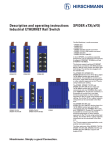
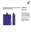
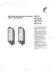
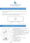
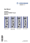
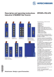
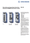
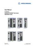
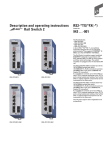
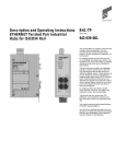
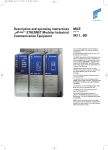
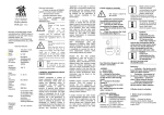
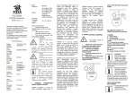
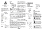
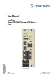
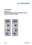
Description and operating instructions
i Rail Switch 2
RS2-TX
i
P
1
2
FAULT
1
3
5
7
2
4
6
8
RS2-TX
Bestell-Nr.
943 686-001
The Rail Switch RS2 has been especially
designed for use in industrial environments.
It supports ETHERNET 10 MBit/s and Fast
ETHERNET 100 MBit/s.
DA/STAT
1
2
The Rail Switch modules support switched
ETHERNET networks in accordance with
IEEE standard 802.3 or 802.3u using copper
technology. The switch modules are plugged onto the standard bar.
3
4
The RS2-TX modules have eight 10/100
MBit/s twisted pair ports (RJ45 connectors).
5
6
7
8
+24V*
+24V
LA1
LA2
LA3
LA4
LA5
LA6
LA7
LA8
FAULT
0 1
It is possible to connect up to eight data terminal equipments or other network segments to the 10/100 Mbit/s ports using twisted pair cabling. The ports support auto
negotiation and autopolarity.
We have checked that the contents of the
technical publication agree with the hardware and software described. However, it is
not possible to rule out deviations completely, so we are unable to guarantee complete agreement. However, the details in the
technical publication are checked regularly.
Any corrections which prove necessary are
contained in subsequent editions. We are
grateful for suggestions for improvement.
We reserve the right to make technical
modifications.
Permission is not given for the circulation
or reproduction of this document, its use or
the passing on of its contents unless granted expressly. Contravention renders the
perpetrator liable for compensation for
damages. All rights reserved, in particular
in the case of patent grant or registration of
a utility or design.
Copyright ©
© Richard Hirschmann GmbH & Co. 1999
All Rights Reserved
General
Safety guidelines
v
Warning!
The RS2-TX units are designed for
operation with safety extra-low voltage. Accordingly, only safety extralow voltages (SELV) to
IEC950/EN60950/VDE0805 may be
connected to the supply voltage
connections.
ESD protection
The modules contain components highly
sensitive to electrostatic fields. These components can be easily destroyed or have
their lives shortened by an electrical field or
by a discharge caused by touching the card.
For these reasons, the modules are delivered in a conducting ESD protective bag. This
packing can be reused.
Be sure to observe the following precautions for electrostatic sensitive devices when
handling the components:
M Establish electrical potential equality between yourself and your surroundings, e.g.
with the aid of a wrist bracelet.
M Only then remove the modules from the
conducting bag.
Electricity is used to operate this equipment. Comply in every detail with the safety
requirements specified in the operating
instructions regarding the voltages to
apply!
M Store the modules in its conducting bag
whenever it is not in the chassis.
Warning!
If warning notes are ignored, it is
therefore possible for severe injuries
and/or material damage to occur.
You can find more information about devices vulnerable to electrostatic fields in
DIN/IEC 47 (Sec) 1330; February 1994 Edition and DIN EN 100 015.
v
Only appropriately qualified staff
should work on or near this equipment. Such staff must be thoroughly
acquainted with all the warnings
and maintenance measures contained in these operating instructions.
The proper and safe operation of
this equipment assumes proper
transport, appropriate storage and
assembly and careful operation and
maintenance.
Staff qualification
requirements
Qualified staff within the meaning of these
operating instructions or the warning notes
are persons familiar with setting up, assembling, starting up and operating this product
and who have appropriate qualifications to
cover their activities, such as:
– training or instruction/entitlement to
switch circuits and equipment/systems on
and off, earth them and identify them in
accordance with current safety standards;
– training or instruction in accordance with
current safety standards in looking after
and using appropriate safety equipment;
– first aid training.
2
ESD protective field kits are available for
working with electrostatic sensitive devices.
1. Functional description
i
P
Multi address capability
An RS2-TX learns all source addresses per
port. Only packets with
– unknown addresses
– addresses learnt at this port
– a multi/broadcast address
in the destination address field are sent to
this port.
An RS2-TX learns up to 1,000 addresses.
This becomes necessary if more than one
terminal device is connected to one or more
ports. In this way several independent subnetworks can be connected to an RS2-TX.
Learnt addresses
An RS2-TX monitors the age of the learned
addresses. The RS2-TX deletes address
entries from the address table which exceed
a certain age (30 seconds).
Note: Restarting deletes the learned
address entries.
Tagging (IEEE 802.1Q)
The IEEE 802.1 Q standard designates the
VLAN tag to be included in a MAC data
frame for the VLAN and prioritizing functions. The VLAN tag consists of 2 bytes. It is
inserted between the source address field
and the type field. Data packets with VLAN
tag are transmitted unchanged by the RS2TX.
1.2 SPECIFIC FUNCTIONS OF THE
TP/TX INTERFACE
Link control
The RS2-TX monitors the connected TP/TX
line segments for short-circuit or interrupt
using regular link test pulses in accordance
with IEEE standard 802.3 10/100BASE-T/TX.
The RS2-TX does not transmit any data to a
TP/TX segment from which it does not
receive a link test pulse.
Note: A non-occupied interface is assessed
as a line interrupt. The TP/TX line to terminal equipment which is switched off is likewise assessed as a line interrupt as the deenergised bus coupler cannot transmit link
test pulses.
Auto polarity exchange
If the receive line pair is incorrectly connected (RD+ and RD- switched) polarity is automatically reversed.
2
FAULT
3
5
7
2
4
6
8
LA1
LA2
LA3
LA4
LA5
LA6
LA7
LA8
FAULT
0 1
8poliger
DIP-Schalter
1.1 FRAME SWITCHING FUNCTIONS
Store and Forward
All data received by the RS2-TX from the
system bus or at the ports are stored and
checked for validity. Invalid and defective
frames (> 1.522 byte or CRC error) as well
as fragments (< 64 byte) are discarded. The
RS2-TX forwards the valid frames.
1
1
DA/STAT
+24V*
LED Anzeigeelemente
+24V
The 10/100BASE-T(X) ports of an RS2-TX
represent a terminal connection for the
connected LAN segment. You can connect
single devices or complete network segments.
RS2-TX
steckbarer
Klemmblock
5polig
1
2
3
4
5
6
7
8
8 Ports nach 10/100BASE-T(X)
(Ports 1 bis 8), RJ45-Anschlüsse
Autonegotiaton + Autopolarity
Fiig. 1: Overview interfaces, display elements and controls of the RS2-TX
1.3 FURTHER FUNCTIONS
AND FEATURES
Reset
The RS2-TX will be reset by the following
action:
– input voltages fall below a threshold
of ports 1 to 8 is suppressed. State on delivery: switch position 1 (on), i.e. message
not suppressed.
0
LA1
LA2
LA3
LA4
LA5
LA6
LA7
LA8
After a reset the following action is carried
through:
– initialization
1.4 DISPLAY ELEMENTS
Equipment status
These LEDs provide information about statuses which affect the function of the entire
RS2-TX.
P1 – Power 1 (green LED)
– lit:
– supply voltage 1 present
– not lit: – supply voltage 1 less than 9.6 V
P2 – Power 2 (green LED)
– lit:
– supply voltage 2 present
– not lit: – supply voltage 2 less than 9.6 V
FAULT – Failure (red LED)
– lit:
– The indicator contact is
open, i.e. it indicates an
error.
– not lit:
– The indicator contact is
closed, i.e. it does not
indicate an error.
Port Status
These LEDs display port-related information.
DA/STAT 1 to 8 – Data, Link status
(green/yellow LED)
– not lit:
– no valid link
– lit green:
– valid link
– flashes yellow:– receiving data
1.5 CONTROLS
8-pin DIP switch
Using the 8-pin DIP switch on the RS2-TX
front panel
– the message about the link statuses can
be suppressed by the indicator contact on
a port-by-port basis. Using switches LA1
to LA8, the message about the link status
1
Port 1
Port 2
Port 3
Port 4
Port 5
Port 6
Port 7
Port 8
Meldung des Linkstatus
über den Meldekontakt
unterdrücken
Fig. 2: 8-pin DIP switch on RS2-TX
1.6 INTERFACES
10/100 MBit/s connection
Eight 10/100 Mbit Ports (ports 1 to port 8, 8pin R45 sockets) on RS2-TX allow terminal
equipment or eight independent network
segments complying with the standards
IEEE 802.3 100BASE-TX / 10BASE-T to be
connected. These ports support autonegotiation and the autopolarity function.
The socket casings are electrically connected to the front panel of the RS2-TX.The pin
configuration complies with MDI-X.
– Pin configuration of the RJ45 socket:
– TD+: pin 3, TD-: pin 6
– RD+: pin 1, RD-: pin 2
– remaining pins: not used.
n.c.
n.c.
TDn.c.
n.c.
TD+
RDRD+
Pin 8
Pin 7
Pin 6
Pin 5
Pin 4
Pin 3
Pin 2
Pin 1
Fig. 3: Pin configuration of an TP/TX
interface
3
Warning!
The RS2-TX equipment is designed
for operation with SELV. Only safety
extra-low voltages to
IEC950/EN60950/VDE0805 may
therefore be connected to the
supply voltage connections and to
the indicator contact.
– Voltage supply: Redundant voltage supplies are supported. Both inputs are
decoupled. There is no load distribution.
With redundant supply, the power pack
supplies the RS2-TX only with the higher
output voltage. The supply voltage is electrically isolated from the housing.
– Indicator contact:
The indicator contact is used to supervise
the functions of the RS2-TX and thus facilitates remote diagnosis without management software.
Contact interrupt indicates the following
by means of a potential-free indicator
contact (relay contact, closed circuit):
– the failure of at least one of the two
supply voltages.
– a permanent fault in the RS2-TX (internal 3,3 V DC voltage, supply voltage 1 or
2 < 9.6 V, ...).
– the faulty link status of at least one port.
The indication of the link state on the
RS2-TX can be masked on a port-by-port
basis using the DIP switches LA1 to LA8.
State of delivery: there is no link test.
Note: In the case of the voltage supply
being routed without redundancy, the RS2TX indicates the failure of a supply voltage.
You can prevent this message by feeding in
the supply voltage through both inputs.
FAULT
+24V*
v
+24V
5pin terminal block
The supply voltage and the indicator
contact are connected via a 5pin terminal
block.
M Attach the upper snap-on slide bar of
the RS2-TX to the standard bar and press it
down until it locks in position.
M Fit the signal lines.
Notes:
– The front panel of the RS2-TX is grounded
via a separate ground connection.
– Do not open the housing.
Fig. 5: Pin configuration of 5pin terminal
block
– The shielding ground of the twisted pair
lines which can be connected is electrically connected to the front panel.
Ground connection
The RS2-TX is grounded via a separate
screw connection.
2. Configuration
2.1 CONNECTING DTE AND OTHER
NETWORK SEGMENTS
It is possible to connect up to eight data terminal equipments (DTE) or other network
segments to the 10/100 Mbit/s ports of the
RS2-TX using twisted pair cabling (ref. Fig.
4).
3. Assembly, startup procedure
and dismantling
3.1 UNPACKING, CHECKING
M Check whether the package was delivered complete (see scope of delivery).
M Check the individual parts for transport
damage.
v
Fig. 6: Assembling the RS2-TX
Warning!
Use only undamaged parts!
3.2 ASSEMBLY
The equipment is delivered in a ready-tooperate condition. The following procedure
is appropriate for assembly:
M Check whether the switch pre-setting
suits your requirements (see chap. 1.5).
M Pull the terminal block off the RS2-TX
and wire up the supply voltage and indicator lines.
M Fit the RS2-TX on a 35 mm standard bar
to DIN EN 50 022.
3.3 STARTUP PROCEDURE
M You start up the RS2-TX by connecting
the supply voltage via the 5-pin terminal
block.
3.4 DISMANTLING
M To take the RS2-TX off the ISO/DIN rail,
insert a screwdriver horizontally under the
housing into the locking slide, pull it (without tipping the screwdriver) downwards
and lift the RS2-TX upwards.
4. Further support
In the event of technical queries, please talk
to the Hirschmann contract partner responsible for looking after your account or directly to the Hirschmann office. You can find
the addresses of our contract partners
– on the Internet
(http://www.hirschmann.de).
Our support line is also at your disposal:
Tel. +49(7127) 14-1538 (Fax -1542)
RS2-TX
Fig. 4: Configuration with RS2-TX: Connection of up to 8 data terminal
equipments or further segments via TP/TX
4
Answers on frequently asked questions you
will find in the Internet pages of Hirschmann: www.hirschmann.de. In the Network
Systems Division on the SERVICES pages
you will find the catagory FAQ with HiVision.
5. Technical data
General data
Operating voltage
Current consumption
DC 9.6 V…57.6 V safety extra-low voltage (SELV) (redundant inputs decoupled)
125 mA typ., at 24 VDC, no link
280 mA maximum, at 24 VDC, 8 ports full load
Overload current protection at input
Dimensions W x H x D
Weight
Ambient temperature
Storage temperature
Humidity
Protection class
Radio interference level
non-changeable thermal fuse
47 mm x 135 mm x 111 mm
1.9 in x 5.3 in x 4.4 in
230 g
5.07 lb
0 ºC to + 60 ºC
32 ºF to 140 ºF
- 20 ºC to + 80 ºC
-4 ºF to 176 ºF
up to 90% (non condensing)
IP 20
EN 55022 Class A
Warning!
This is a Class A Equipment. This equipment may cause radio interference if used in a residential area; in this case it is the operator´s responsibility to take apropriate measures.
EN 50082-2
Interference immunity
Network size
TP/TX port 10BASE-T/100BASE-TX
Length of a twisted pair segment
100 m (328 ft) maximum
Interfaces
8 TP/TX ports
Indicator contact
RJ45 sockets, 10/100 MBit/s
1 A maximum, 24 V
Displays
Equipment status
Port status
1 x green LED
1 x green LED
1 x red LED
8 x green/yellow LED
P1 – power 1, supply voltage 1 present
P2 – power 2, supply voltage 2 present
FAULT – indicator contact is open and indicates error
DAT/STAT 1 to 8 – data, link status
Controls
8-pole DIP switch
LA1 to LA8 – suppress message about the link statuses
Scope of delivery
Rail Switch RS2-TX incl.
terminal block for supply voltage
description and operating instructions
Order number
Rail Switch RS2-TX
943 686-001
Accessories
ETHERNET manual
943 320-011
5
Notes on CE identification
The devices comply with the regulations of the following European
directive:
89/336/EEC
Council Directive on the harmonization of the legal regulations of
member states on electromagnetic
compatibility (amended by Directives 91/263/EEC, 92/31/EEC and
93/68/EEC).
0
Area used
Industrial
The EU declaration of conformity is kept
available for the responsible authorities in
accordance with the above-mentioned EU
directives at:
Richard Hirschmann GmbH & Co.
Automation and Networking Solutions
Stuttgarter Straße 45-51
D-72654 Neckartenzlingen
Telephone ++49-7127-14-1538
FCC Note:
This equipment has been tested and
found to comply with the limits for a
Class A digital device, persuant to
part 15 of the FCC Rules. These
limits are designed to provide reasonable protection against harmful
interference when the equipment is
operated in a commercial environment. This equipment generates,
uses, and can radiate radio frequency energy and, if not installed and
Richard Hirschmann GmbH & Co.
Automation and Networking Solutions Division
Stuttgarter Str. 45-51
D-72654 Neckartenzlingen
Telephone ++49 - 7127 14 1538
Printed in Germany
Requirements for
emitted interference
interference immunity
EN 50081-2: 1993
EN 50082-2: 1995
EN 55022 Class A: 1998
used in accordance with the instruction manual, may cause harmful
interference to radio communications. Operation of this equipment in
a residential area is likely to cause
harmful interference in which case
the user will be required to correct
the interference at his own expense.
The product can be used in the residential sphere (residential sphere, business
and trade sphere and small companies)
and in the industrial sphere.
The precondition for compliance with
EMC limit values is strict adherence to
the construction guidelines specified in
this description and operating
instructions.
,
Recycling Note:
After its use, this product has to be
processed as electronic scrap to a
proper disposal according to the prevailing waste disposal regulations of
your community / district / country /
state.
039616001011199000