1
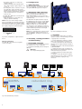
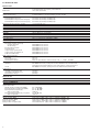
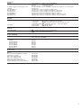
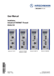
Description and operating instructions RS2-4R
Industrial ETHERNET Rail Switch 2 Family
The Rail Switch RS2 has been especially
designed for use in industrial environments.
It supports ETHERNET 10 MBit/s and Fast
ETHERNET 100 MBit/s.
The RS2-4R devices
– RS2-4R
– RS2-4R 1MM SC
– RS2-4R 1SM SC
– RS2-4R 1LH SC
– RS2-4R 2MM SC
– RS2-4R 2SM SC
– RS2-4R 2LH SC
are manageable. They support SNMP and
Web based management.
The Rail Switch devices support switched
ETHERNET networks in accordance with
IEEE standard 802.3 using copper technology or optical waveguide (F/O), in line and
ring structures. The switch devices are plugged onto the standard bar.
RS2-4R
RS2-4R 1MM SC
RS2-4R 1SM SC
RS2-4R 1LH SC
RS2-4R 2MM SC
RS2-4R 2SM SC
RS2-4R 2LH SC
Depending on the model, the RS2-4R devices have two to four 10/100 Mbit/s twisted
pair (TP/TX) ports (RJ45 connectors) and up
to two fiber optic ports (100 Mbit/s ports).
The fiber optic ports to connect further
more switches are available with FX interfaces (depending on the RS2-4R model with
multimode, singlemode or Long Haul, DSC
connectors):
– RS2-4R:
4 x TP/TX
– RS2-4R 1…: 3 x TP/TX, 1 x FX
– RS2-4R 2…: 2 x TP/TX, 2 x FX
It is possible to connect data terminal
equipments or other network segments to
the 10/100 Mbit/s ports using twisted pair
cabling TP/TX. The ports support autonegotiation, autopolarity and autocrossing.
The RS2-4R devices in addition have one
V.24 interface for external management.
In the„RS2-4R Management Manual – Industrial ETHERNET Rail Switch 2“ you find a
detailled description on the RS2-4R Rail
Switch.
F, the Hirschmann network management system, is the optimum management
solution for this product. Your sales partner
keeps information ready.
The performance features described here
are binding only if they have been expressly
guaranteed in the contract. We have
checked that the contents of the technical
publication agree with the hardware and
software described. However, it is not possible to rule out deviations completely, so we
are unable to guarantee complete agreement. However, the details in the technical
publication are checked regularly. Any corrections which prove necessary are contained in subsequent editions. We are grateful
for suggestions for improvement.
We reserve the right to make technical
modifications.
Permission is not given for the circulation
or reproduction of this document, its use or
the passing on of its contents unless granted expressly. Contravention renders the
perpetrator liable for compensation for
damages. All rights reserved, in particular
in the case of patent grant or registration of
a utility or design.
z
Note: is an important piece of information
about the product, how to use the product,
or the relevant section of the documentation to which particular attention is to be
drawn.
Certified usage
We would point out that the content of
these operating instructions is not part of,
nor is it intended to amend an earlier or existing agreement, permit or legal relationship. All obligations on Hirschmann arise
from the respective purchasing agreement
which also contains the full warranty conditions which have sole applicability. These
contractual warranty conditions are neither
extended nor restricted by comments in
these operating instructions.
We would furthermore point out that for
reasons of simplicity, these operating
instructions cannot describe every
conceivable problem associated with the
use of this equipment. Should you require
further information or should particular
problems occur which are not treated in
sufficient detail in the operating instructions, you can request the necessary information from your local Hirschmann sales
partner or directly from the Hirschmann
office (address: refer to chapter entitled
„Notes on CE identification“).
Safety Instructions
This manual contains instructions which
must be observed to ensure your own personal safety and to avoid
damage to devices and machinery. The
instructions are highlighted with a warning
triangle and are shown as
follows according to the degree of endangerment:
z
z
2
Danger!
means that death, serious injury or
considerable damage to property
will result if the appropriate safety
measures are not taken.
Warning!
means that death, serious injury or
considerable damage to property
can result if the appropriate safety
measures are not taken.
Safety Guidelines
Shielding Ground
Note: The shielding ground of the connectable twisted pairs lines is connected to the
front panel as a conductor.
Beware of possible short circuits when
connecting a cable section with conductive
shielding braiding.
Safety Guidelines Housing
Please observe the following:
z
Copyright
© Hirschmann Electronics GmbH & Co. KG 2004
All Rights Reserved
Note
Caution!
means that light injury or damage to
property can result if the appropriate safety measures are not taken.
Warning
The device may only be employed
for the purposes described in the
catalog and technical description,
and only in conjunction with external
devices and components recommended or approved by Hirschmann.
The product can only be operated
correctly and safely if it is transported, stored, installed and assembled
properly and correctly. Furthermore,
it must be operated and serviced
carefully.
z
Note: The device is grounded via the separated ground screw. It is located on the left
under the front panel.
Make sure that the electrical installation
meets local or nationally applicable safety
regulations.
z
Safety Guidelines
Power Supply
Warning!
The devices may only be connected
to the supply voltage shown on the
type plate.
The devices are designed for
operation with a safety extra-low
voltage.Thus, they may only be
connected to the supply voltage
connections and to the signal
contact with PELV circuits or
alternatively SELV circuits with the
voltage restrictions in accordance
with IEC/EN 60950.
For the case where the module is operated with external power supply: Use only a
safety extra-low voltage in accordance with
IEC 950/EN 60 950/VDE 0805 to power the
system.
First of all you connect the protecting
line, before you establish the further
connections. When you remove connections, you disconnect the protecting line
last.
Relevant for North America:
The subject unit is to be suppplied by a
Class 2 power source complying with the
requirements of the National Electrical
Code, table 11(b). If power is redundant
supplied (two individual power sources) the
power sources together should comply with
the requirements of the Na-tional Electrical
Code, table 11 (b).
Relevant for North America:
Use 60/75°C or 75°C copper(CU)wire only.
Warning!
The ventilation slits must not be
covered so as to ensure free air circulation.
The distance to the ventilation slots
of the housing has to be a minimum
of 10 cm.
Switch the basic devices on only when
the case is closed.
z
Warning!
Only technicians authorized by Hirschmann are permitted to open the
housing.
Never insert pointed objects (thin
screwdrivers, wires, etc.) into the
inside of the subrack! Failure to
observe this point may result in injuries caused by electric shocks.
Note: According to EN 60950 the device
may only be operated in a fire protective
housing.
Note: The housing has to be mounted in
upright position.
Safety Guidelines Environment
z
Warning!
The device may only be operated in
the listed maximum surrounding air
temperature range at the listed
relative air humidity range (noncondensing).
The installation location is to be selected so as to ensure compliance with the climatic limits listed in the Technical Data.
To be used in a Pollution Degree 2 environment only.
Staff qualification
requirements
Note: Qualified personnel, as understood
in this manual and in the warning signs, are
persons who are familiar with the setup,
assembly, startup, and operation of this
product and are appropriately qualified for
their job. This includes, for example, those
persons who have been:
– trained or directed or authorized to
switch on and off, to ground and to label
power circuits and devices or systems in
accordance with current safety engineering standards
– trained or directed in the care and use of
appropriate safety equipment in accordance with the current standards of safety
engineering
– trained in providing first aid.
General Safety Instructions
This device is electrically operated.
Adhere strictly to the safety requirements
relating to voltages applied to the device as
described in the operating instructions!
z
Warning!
Failure to observe the information
given in the warnings could result in
serious injury and/or major damage.
Only personnel that have received
appropriate training should operate
this device or work in its immediate
vicinity. The personnel must be fully
familiar with all of the warnings and
maintenance measures in these
operating instructions.
Correct transport, storage, and
assembly as well as careful operation and maintenance are essential in
ensuring safe and reliable operation
of this device.
Use only undamaged parts!
These products are only to be used in
the manner indicated in this version of the
”Description and Operating Instructions”.
Particular attention is to be paid to all
warnings and items of information relating
to safety.
z
z
Warning!
Any work that may have to be performed on the electrical installation
should be performed by fully
qualified technicians only.
Warning!
LED- or LASER components according to IEC 60825-1 (2001):
CLASS 1 LASER PRODUCT.
LIGHT EMITTING DIODE - CLASS 1
LED PRODUCT.
Based specifications and
standards:
The devices fulfil the following
specifications and standards:
– EN 61000-6-2:2001 Generic standards –
Immunity for industrial environments
– EN 55022:1998 + A1 2000 – Information
technology equipment – Radio disturbance characteristics
– EN 60950:1997 – Safety of Information
Technology Equipment (ITE)
– EN 61131-2:1994 + A12 2000 –
Programmable Controllers
– FCC 47 CFR Part 15:2000 – Code of Federal
Regulations
– Germanischer Lloyd, Rules for
Classification and Construction VI - 7 - 3
Part 1, Ed. 2001.
– cUL 508:1998 – Underwriters Labratories
Inc. Safety for Industrial Control
Equipment.
– cUL 1604 Electrical Equipment for Use in
Class I and Class II, Div. 2 and Class III
Hazardous (Classified).
– cUL 60950 Safety for Information
Technology Equipment.
Certified devices are marked with a
certification identifier.
on CE
7 Notes
identification
The devices comply with the regulations of the following European
directive:
89/336/EEC
Council Directive on the harmonization of the legal regulations of member states on electromagnetic compatibility (amended by Directives
91/263/EEC, 92/31/EEC and
93/68/EEC).
z
Warning!
This is a Class A device. This equipment may cause radio interference if
used in a residential area; in this
case it is the operator´s responsibility to take appropriate measures.
The precondition for compliance
with EMC limit values is strict adherence to the construction guidelines
specified in this description and
operating instructions.
FCC Note:
This equipment has been tested and found
to comply with the limits for a Class A digital device, persuant to part 15 of the FCC
Rules. These limits are designed to provide
reasonable protection against harmful interference when the equipment is operated in
a commercial environment. This equipment
generates, uses, and can radiate radio frequency energy and, if not installed and
used in accordance with the instruction
manual, may cause harmful interference to
radio communications. Operation of this
equipment in a residential area is likely to
cause harmful interference in which case
the user will be required to correct the interference at his own expense.
,
Recycling Note:
After its use, this product has to be
processed as electronic scrap and
disposed of according to the prevailing waste disposal regulations of
your community / district / country /
state.
The EU declaration of conformity is
kept available for the responsible
authorities in accordance with the
above-mentioned EU directives at:
Hirschmann Electronics
GmbH & Co. KG
Automation and Network Solutions
Stuttgarter Straße 45-51
D-72654 Neckartenzlingen
Telephone ++49 (0)7127 14-1480
The product can be used in the residential sphere (residential sphere,
business and trade sphere and small
companies) and in the industrial
sphere.
– Interference immunity:
EN 61000-6-2:2001
– Radio interference level:
EN 55022:1998 + A1 2000 Class A
3
1. Functional description
Note: A non-occupied interface is assessed
as a line interrupt. The TP/TX line to terminal equipment which is switched off is likewise assessed as a line interrupt as the deenergised bus coupler cannot transmit link
test pulses.
Auto polarity exchange
If the receive line pair is incorrectly connected (RD+ and RD- switched) polarity is automatically reversed.
Autonegotiation
Autonegotiation is a procedure in which the
switch automatically selects the operating
mode of its 10/100 RJ-45 ports. When a
connection is set up for the first time, the
switch detects the speed (10 or 100 Mbit/s)
and the transmission mode of the connected network (half duplex or full duplex).
Autocrossing
If the autonegotiation function is active, the
RS2-4R detects the transmit and receive
pairs (MDI, MDI-X). The RS2-4R automatically configures its port for the correct
transmit and receive pins. Consequently it
does not matter whether you connect devices using a cross-over or straight cable.
1.3 SPECIFIC FUNCTIONS OF THE
F/O INTERFACE
Link control
According to IEEE 802.3 standard 100BASEFX an RS2-4R monitors the attached F/O
lines for open circuit conditions.
1.4 REDUNDANCY FUNCTIONS
If a line section fails, the redundancy functions “HIPER-Ring” solves a network interruption within less than 0.5 seconds (see
chap. 2).
LS
LS
DA
DA
DA
2
2
FAULT
4
4
LS
LS
LS
MAC address field
IP address field
2 HIPER-Ring ports (port 3 and 4)
LED
display
elements
Port 4
RS2-4R
1MM SC
1SM SC
1LH SC
2MM SC
2SM SC
2LH SC
Port 3
RS2-4R
1MM SC
1SM SC
1LH SC
2MM SC
2SM SC
2LH SC
LH
DA
4
x
x
x
x
x
x
x
x
x
x
x
x
x
x
Fig. 1: Overview interfaces, display elements and controls of the RS2-4R
1.5 SECURITY
Port security
An RS2-4R protects every port from unauthorized access. The following functions are
available for the security monitoring of
every single port:
– Who has access to this port?
– Actions which result on an unauthorized
access
– How to proceed in case of an access of an
unknown user
1.6 FURTHER FUNCTIONS
AND FEATURES
Diagnosis
In case of a reset the RS2-4R runs a hardware self test. During operation an integrated watch dog (monitoring unit) monitors
the function of the software.
Reset
The RS2-4R will be reset by the following
actions:
– management
– input voltages fall below a threshold
– internal voltage supply falls below a
threshold
– watchdog
After a reset the following actions are carried through:
– self test
– initialization
1.7 DISPLAY ELEMENTS
Equipment status
These LEDs provide information about statuses which affect the function of the entire
RS2-4R.
P1 – Power 1 (green LED)
– lit:
– supply voltage 1 present
– not lit: – supply voltage 1 is less than 18 V
4
3
LS
SM
DA
4
DA
LH
3
LS
2
LS
Port 1 and 2 complying
with 10/100BASE-T(X)
autonegotiaton + autopolarity +
autocrossing
(RJ45 connectors)
MM
DA
V.24 interface
for external
management
SM
+24V (P2)
DA
4
LS
2pole
DIP switch
TP
3
LS
Aufkleber MAC-Adresse
1
LS
DA
FAULT
DA
1
LS
0V
0V
RM
RING
V.24
DA
3
Aufkleber MAC-Adresse
Aufkleber MAC-Adresse
1
LED
display
elements
FAULT
RM
0 1
6pin
terminal
block
MM
DA
2
+24V (P2)
IP-ADDRESS
IP-ADDRESS
RM
RING
V.24
1
0V
0V
0 1
RM
RING
V.24
P
FAULT
RM
+24V (P1)
2
IP-ADDRESS
1
FAULT
P
+24V (P2)
FAULT
RM
0V
0V
2
h
RS2-4R
TP
1.2 SPECIFIC FUNCTIONS OF THE
TP/TX INTERFACE
Link control
The RS2-4R monitors the connected TP/TX
line segments for short-circuit or interrupt
using regular link test pulses in accordance
with IEEE standard 802.3 10/100BASE-T/TX.
The RS2-4R does not transmit any data to a
TP/TX segment from which it does not
receive a link test pulse.
1
0 1
+24V (P1)
1.1 FRAME SWITCHING FUNCTIONS
The RS2-4R supports the following frame
switching functions:
– Store and Forward
– Multi address capability
– Learnt addresses
– Priority
– Tagging
– Flow control
– Port mirroring
– Broadcast Limiter
P
h
RS2-4R
+24V (P1)
h
The ports of an RS2-4R represent a terminal
connection for the connected LAN segment.
You can connect single devices or complete
network segments.
RS2-4R
P2 – Power 2 (green LED)
– lit:
– supply voltage 2 present
– not lit: – supply voltage 2 is less than 18 V
FAULT – Failure (red LED)
– lit:
– The indicator contact is
open, i.e. it indicates an
error.
– not lit:
– The indicator contact is
closed, i.e. it does not
indicate an error.
If the manual setting of the indicator contanct is active, the fault LED does not
depend on the position of the indicator
contact.
RM – Redundancy Manager
(green/yellow LED)
– lit green:
– RM function active,
redundant port not active
– lit yellow:
– RM function active,
redundant port active
– not lit:
– RM function not active
– flashes green 2 times
per second
– Configuration is loaded
from ACA
– flashes yellow 2 times
per second
– Configuration is saved to
ACA
– flashes green/yellow 2 times
per second
– Error in memory
operation
– flashes green 1 time
per second
– HIPER-Ring configuration
error, e.g. no RM or
several RMs active
Port Status
These LEDs display port-related information.
LS 1 to 4 – Link state (green LED)
– not lit:
– no valid link
– lit green:
– valid link
– blinking green (1 single blink per period)
– port is deactivated by RM
(port 3, if RM active)
– blinking green (3 blinks per period)
– port is disabled
– running light: – initialization phase after a
reset
DA 1 bis 4 – Data (yellow LED)
– not lit:
– no data traffic
– flashes yellow:– data traffic
– running light: – initialization phase after a
reset
1.8 CONTROLS
2-pin DIP switch
Using the 2-pin DIP switch on the RS2-4R
front panel
– on RS2-4R the HIPER-Ring function can be
enabled or disabled with the switch RING.
State of delivery: position 0 (Off), i.e. normal function.
– with the RM switch the RM functionality
(Redundancy Manager) can be switched
on or off when HIPER-Ring function is
activated. State of delivery: switch in position 0 (Off), i.e. RM function not active.
0
1
RM
RING
Redundancy manager
HIPER-Ring
Fig. 2: 2-pin DIP switch on RS2-4R
RING RM port 3 + 4
0
-
1
1
0
1
Redundancy
Manager
TP port: Autonegotiation
off
FX port: 100 Mbit/s fullduplex
Ring port: 100 Mbit/s fulldupl
off
Ring port: 100 Mbit/s fulldupl.
on
Tab. 1: DIP switch function
1.9 INTERFACES
10/100 MBit/s connection
(Twisted Pair)
10/100 Mbit Ports (8-pin R45 sockets) allow
terminal equipment or independent network segments complying with the standards IEEE 802.3 100BASE-TX / 10BASE-T
to be connected. These ports support autonegotiation, autocrossing and the autopolarity function.
Factory settings: autonegotiation active (not
valid for HIPER-Ring ports).
The socket casings are electrically connected to the front panel of the RS2-4R.The pin
configuration complies with MDI-X.
RS2-4R
RS2-16M
– Pin configuration of the RJ45 socket,
RS2-4R:
– 1 line pair: pin 3 and pin 6
– 1 line pair: pin 1 and pin 2
– remaining pins: not used.
Pin 8
Pin 7
Pin 6
Pin 5
Pin 4
Pin 3
Pin 2
Pin 1
RJ11
DB9
Pin 5
Pin 8
Pin 6
Pin 1
Pin 1
CTS
n.c.
TX
GND
RX
RTS
1
2
3
4
5
6
2
3
5
Fig. 4: Pin configuration of the V.24
interface
Fig. 3: Pin configuration of an TP/TX
interface
100 Mbit/s connection
100 MBit/s F/O ports (DSC sockets) allow
terminal equipment or independent
network segments complying with the
standard IEEE 802.3 100BASE-FX to be
connected.
State on delivery: full duplex.
Note: Make sure, that you conncet LH ports
only to LH ports, SM ports only to SM ports
and MM ports only to MM ports.
V.24 interface (external management)
A serial interface for local connection of
– an external management station (VT100
terminal or a PC with corresponding terminal emulation) is available via the RJ11
socket (V.24 interface). A link can thus be
established with the User Interface UI.
– an AutoConfiguration Adapter ACA 11 is
available via the RJ11 socket (V.24 interface).
VT100 terminal settings:
– Speed:
9,600 Baud
– Data:
8 bit
– Stopbit:
1 bit
– Handshake: off
– Parity:
none
The V.24 interface baud rate can be configured to 9,600 or 19,200 baud. The factory
default is 9,600 baud.
The socket casing is galvanically connected
to the front panel of the device.
Note: In chapter 6 „Technical data“ you
find the order number for the terminal
access cable which is to be ordered
separately.
– AutoConfiguration Adapter ACA:
The ACA is a device for saving the configuration data of a MICE, RS2-4R, RS216M, RS2../.. oder MACH 3000 switch. If
one switch should fail, the ACA facilitates
a conceivable simple assumption of the
configuration data by an alternative
switch of the same type.
In case of a reset the switch compares the
contents of the ACA with its own configuration data. If the configuration data do
not correspond, the switch takes over the
configuration data of the ACA.
6pin terminal block
The supply voltage and the indicator
contact are connected via a 6pin terminal
block with screw rast mechanism.
z
Warning!
The RS2-4R equipments are designed for operation with a safety
extra-low voltage.Thus, they may
only be connected to the supply voltage connections and to the signal
contact with PELV circuits or
alternatively SELV circuits with the
voltage restrictions in accordance
with IEC/EN 60950.
– Voltage supply: Redundant voltage supplies are supported. Both inputs are
decoupled. There is no load distribution.
With redundant supply, the power pack
supplies the RS2-4R only with the higher
output voltage. The supply voltage is electrically isolated from the housing.
– Indicator contact:
The indicator contact is used to supervise
the functions of the RS2-4R and thus facilitates remote diagnosis.
Contact interrupt indicates the following
by means of a potential-free indicator
contact (relay contact, closed circuit):
RS2-../..
RS2-16M
RS1
MICE
Line structure
Fig. 5: Line structure
5
– the failure of at least one of the two
supply voltages.
– a permanent fault in the RS2-4R (internal voltage supply, supply voltage 1 or 2
< 18 V, ...).
– the faulty link status of at least one port.
The indication of the link state on the
RS2-4R can be masked on a port-by-port
basis using the management software.
State of delivery: there is no link test.
– self test error
The RS2-4R in RM mode can indicate the
following states:
– Ring monitoring is not possible, e. g.
during software initializing.
2.1 LINE STRUCTURE
The RS2-4R enables backbones in line structures to be built up. Cascading is effected
using the HIPER-Ring ports (see Fig. 5).
2.2 REDUNDANT RING STRUCTURE
With the RM function (redundancy manager) of the RS2-4R, RS2-16M, RS2-../..,
MICE, MACH 3000 you can close the two
ends of a line structured backbone to form a
redundant ring.
The RS2-4R is integrated into the ring via
the HIPER-Ring ports (ports 3 and 4). Within
a redundant ring any mixture of RS1, RS24R, RS2-16M, RS2-../.., MICE and MACH
3000 is possible. If one section fails the
recovery time is less than 0.5 seconds for a
ring containing up to 50 switches being cascaded and the ring structure is changed
back into a line structure.
Note: The „redundant ring“ function requires the following settings for the ports 3
and 4: 100 Mbit/s, full duplex and autonegotiation off.
+24 V (P2)
0V
0V
Fault
+24 V (P1)
Note: In the case of the voltage supply
being routed without redundancy, the RS24R indicates the failure of a supply voltage.
You can prevent this message by feeding in
the supply voltage through both inputs.
2. Configuration
Fig. 6: Pin configuration of 6pin terminal
block
3. Assembly, startup procedure
and dismantling
Ground connection
The RS2-4R is grounded via a separate
screw connection.
3.1 UNPACKING, CHECKING
Check whether the package was delivered complete (see scope of delivery).
Check the individual parts for transport
damage.
z
Warning!
Use only undamaged parts!
Fig. 8: Assembling the RS2-4R
3.2 ASSEMBLY
The equipment is delivered in a ready-tooperate condition. The following procedure
is appropriate for assembly:
Check whether the switch pre-setting
suits your requirements (see chap. 1.7).
Pull the terminal block off the RS2-4R
and wire up the supply voltage and indicator lines.
Fit the RS2-4R on a 35 mm standard bar
to DIN EN 50 022.
Attach the upper snap-on slide bar of
the RS2-4R to the standard bar and press it
down until it locks in position.
Fit the signal lines and if required the
control line.
Always connect the main line and the
redundant line to port 1 (state on delivery)
for the redundant coupling of ring
structures.
RS2-../..
RS2-../..
RS2-16M
RS1
RS1
MICE
redundant ring
ring closed by MICE with
switch RM on position "ON"
MICE
RS2-4R
MICE
Fig. 7: Redundant ring structure
6
RS2-16M
MICE
MICE
RS2-../..
Notes:
– The front panel of the RS2-4R is grounded via a separate ground connection.
– Do not open the housing.
– The shielding ground of the twisted pair
lines which can be connected is electrically connected to the front panel.
3.3 STARTUP PROCEDURE
You start up the RS2-4R by connecting the
supply voltage via the 6-pin terminal block.
3.4 BASIC SETTINGS
On the first installation of the RS2-4R you
have to enter the IP addresse(s). The RS24R provides 4 possibilities to configure the
IP addresses (refer to RS2-4R manual):
– Configuration via BOOTP (bootstrap protocol)
– Configuration via DHCP (dynamic host
configuration protocol)
– Input via the V.24 interface
– AutoConfiguration Adapter
3.5 DISMANTLING
To take the RS2-4R off the ISO/DIN rail,
insert a screwdriver horizontally under the
housing into the locking slide, pull it (without tipping the screwdriver) downwards
and lift the RS2-4R upwards.
4. Management
4.1 INTODUCTION
The RS2-4R supports SNMP and Web-based
management and thus offers a extensive
diagnosis and configuration functions for
an easy startup procedure as well as extensive network- and device information. The
RS2-4R supports the TCP/IP protocol family.
You will find detailed descriptions regarding
the SNMP management, functionality of the
User Interface, web interface, system monitors, software update and Management
Information Base MIB in the RS2-4R
manual.
4.2 SNMP MANAGEMENT
Factory settings: All parameters which can
be adjusted via management are pre-set to
default values. You will find detailed
descriptions in the RS2-4R manual.
4.3 USER INTERFACE
The User Interface (UI) can be used in addition to the web interface.
On the first installation of the RS2-4R you
have to enter IP addresse(s). If you do not
have a VT100 terminal near the installation
place at your disposal, you can enter the IP
addresses before the final installation. For
that you need a VT100 terminal or a corresponding emulation (e.g. MS windows terminal).
The User Interface starts after pressing any
key.
State of delivery: password „private“
– System parameters
Among others various addresses can be
entered in the window presented on the
screen (IP address, netmask, gateway IP
address) and the IP configuration mode can
be selected.
4.4 WEB-BASED INTERFACE
In order to open the Web-based interface
you need a Web browser (program which
enables to read hypertext), for example the
Netscape Navigator/Communicator from
version 6.0 or the Microsoft Internet Explorer from version 5.5 on.
Note: The Web-based interface uses the
plugin "Java runtime environment version
1.3". If this is not installed on your computer, an installation via the internet is started
automatically on the first start of the Webbased interface. This installation takes a lot
of time. For Windows NT users: Because of
that stop the installation. Install the plugin
from the enclosed CDROM. For that start
the program file
j2re1_3_1_07-windows-i586-i.exe
in the Java table on the CDROM.
5. Further support
In the event of technical queries, please talk
to the Hirschmann contract partner responsible for looking after your account or
directly to the Hirschmann office. You can
find the addresses of our contract partners
– on the Internet
(http://www.hirschmann.de).
Our support line is also at your disposal:
Tel. +49(1805) 14-1538
Fax +49(7127) 14-1551
Answers to Frequently Asked Questions can
be found on the Hirschmann internet site
www.hirschmann.de
The FAQs are located under „Service“ in
the Automation and Network Solutions
section.
www.hicomcenter.com gives you an up-todate overview of training courses about
technology and products.
The web interface is used to access the
object classes of the MIBs via a standard
web browser. Access to the web interface is
protected by a password. If you do not
enter a password, only read access to the
RS2-4R is possible.
Factory setting: password „private“
4.5 SYSTEM MONITORS
System monitor 1
The system monitor 1 is used to load the
operating system via the V.24 interface. It is
required only for service purposes. The
system monitor 1 is available immediately
after the system start (at 9,600 baud).
It offers the following functions:
– Update Operating System: Update the
operating system via X modem/CRC protocol
– Start Operation System: Start operating
system and applications
– Change Baudrate
– End: Quit the monitor program and restart
the system.
System monitor 2
The system monitor 2 is used to update the
complete operating software of the RS2-4R
via V.24 or via the network. It is available
after loading the operating system (at 9,600
baud).
When the software update is started via the
User Interface the monitor is opened
directly.
It offers the following functions:
– Software Update V.24: Update of the operating software
– Software Update tftp: Update of the operating software.
Note: The tftp path has to be defined correctly before the update.
– Cancel Automatic Update: Cancel the
update process
– Change Baudrate
– Restore Factory Settings: The factory settings (without system parameters) replace
a previously saved configuration.
– Reset: RS2-4R boot again
– End/Quit: Quit the monitor program, causes to load the management software.
7
6. Technical data
General data
Operating voltage
Buffer time
NEC Class 2 power source 24 VDC (-25% +33%) safety extra-low voltage (SELV/PELV)
(redundant inputs decoupled), 5 A maximum
min. 10 ms at 24 VDC
Potential difference between input
voltage and housing
Potential difference to input voltage, +24 VDC: 32 VDC
Potential difference to input voltage, ground: -32 VDC
Power consumption
RS2-4R (with 4 TX ports)
RS2-4R (with 3 TX ports and 1 FX port)
RS2-4R (with 2 TX ports and 2 FX ports)
4.8 W max. at 24 VDC; 16.4 Btu (IT)/h
5.5 W max. at 24 VDC; 18.8 Btu (IT)/h
6.8 W max. at 24 VDC; 23.2 Btu (IT)/h
Overload current protection at input
Dimensions W x H x D
Weight
Ambient temperature
Storage temperature
Humidity
Atmospheric pressure
Pollution Degree
Laser protection
Protection type
Interference proof
Discharge of static electricity
Contact discharge
Air discharge
Electromagnetic fields
Fast transients
Surge voltage symmetrical
Surge voltage asymmetrical
Cable-based RF faults
EMC emitted immunity
EN 55022
FCC 47 CFR Part 15
Germanischer Lloyd
Stability
Vibration
Shock
Certifications
cUL 508 / CSA 22.2 No.142
cUL 1604 / CSA 22.2 No.213
Germanischer Lloyd
non-changeable fuse
47 x 131 x 111 mm
325 g
Surrounding air: 40 °C to +70 °C (RS2-4R 1LH SC and RS2-4R 2LH SC: 0 °C to 60 °C)
Surrounding air: -40 °C bis +85 °C
10% to 95% (non condensing)
up to 2000 m (795 hPa, higher altitudes on demand)
2
Class 1 conforming to EN 60825-1 (2001)
IP 20
EN 61000-4-2 Test level 3
EN 61000-4-2 Test level 3
EN 61000-4-3 Test level 3
EN 61000-4-4 Test level 3
EN 61000-4-5 Test level 2
EN 61000-4-5 Test level 3
EN 61000-4-6 Test level 3
Class A
Class A
Rules for Classification and Construction VI - 7 - 3 Part 1, Ed. 2001
IEC 60068-2-6 Test FC, testing level in line with IEC 61131-2 E2 CDV and
Germanischer Lloyd Guidelines for the Performance of Type Tests Part 1
IEC 60068-2-27 Test Ea, testing level in line with IEC 61131-2 E2 CDV
pending
pending
pending
Network size
TX port 10BASE-T/100BASE-TX
Length of a twisted pair segment
F/O port 100BASE-FX
According to IEEE 802.3u 100BASE-FX
System attenuation
50/125 µm fiber (multimode) (MM)
62,5/125 µm fiber (multimode) (MM)
9/125 µm fiber (singlemode)
Wave length (SM)
9/125 µm fiber (singlemode), Longhaul
Wave length (LH)
F/O line length (example)
50/125 µm fiber (MM)
62,5/125 µm fiber (MM)
9/125 µm fiber (SM)
9/125 µm fiber Longhoul (LH)
8
100 m approx.
0 to 8 dB (MM)
0 to 11 dB (MM)
0 to 16 dB (SM)
1300 nm
7 to 29 dB (LH)
1550 nm
5 km approx. (MM) (data of fiber: 1.0 dB/km, 800 MHz*km)
4 km approx. (MM) (data of fiber: 1.0 dB/km, 500 MHz*km)
30 km approx. (SM) (data of fiber: 1300 nm, 0.4 dB/km)
24 to 86.6 km (LH) (data of fiber: 1550 nm, 0.3 dB/km)
Interfaces
RS2-4R
in addition 2 type depending ports each:
–RS2-4R
RS2-4R 1MM SC
RS2-4R 1SM SC
RS2-4R 1LH SC
RS2-4R 2MM SC
RS2-4R 2SM SC
RS2-4R 2LH SC
2 to 4 TP/TX ports (RJ45 sockets,10/100 MBit/s),
V.24 port
external management,
Indicator contact
1 A maximum, 24 V
FX ports with DSC sockets (100 MBit/s), singlemode, multimode or long haul (LH)
4 TP/TX ports
3 TP/TX ports, 1 FX port (multimode / MM, port 4)
3 TP/TX ports, 1 FX port (singlemode 1300 nm / SM, port 4)
3 TP/TX ports, 1 FX port (singlemode 1550 nm / LH, port 4)
2 TP/TX ports, 2 FX ports (multimode / MM, port 3 and 4)
2 TP/TX ports, 2 FX ports (singlemode 1300 nm / SM, port 3 and 4)
2 TP/TX ports, 2 FX ports (singlemode 1550 nm / LH, port 3 and 4)
Displays
Equipment status
Port status
1 x green LED
1 x green LED
1 x red LED
1 x green/yellow LED
4 x green LED
4 x yellow LED
P1 – power 1, supply voltage 1 present
P2 – power 2, supply voltage 2 present
FAULT – indicator contact is open and indicates error
RM – redundancy manager + autoconfig adapter
LS 1 to 4 – link state
DA 1 to 4 – data
Controls
2-pole DIP switch
RM – activate redundancy manager functionality
RING – Aktivierung HIPER-Ring-Funktion
Scope of delivery
Rail Switch RS2-4R incl.
Order number
RS2-4R
RS2-4R 1MM SC
RS2-4R 1SM SC
RS2-4R 1LH SC
RS2-4R 2MM SC
RS2-4R 2SM SC
RS2-4R 2LH SC
terminal block for supply voltage, description and operating instructions
manual RS2-4R on CD-ROM
943 846943 847943 848943 849943 850943 851943 852-
Accessories
ETHERNET manual
Manual
Basics Industrial ETHERNET and TCP/IP
Terminal access cable
Rail Power Supply RPS 30
Rail Power Supply RPS 60
Rail Power Supply RPS 120
AutoConfiguration Adapter ACA 11
Network Management Software HiVision
943 320-011
280 720-834
943 301-001
943 662-003
943 662-001
943 662-011
943 751-001
943 471-100
9
Hirschmann Electronics GmbH & Co. KG
Automation and Network Solutions
Stuttgarter Straße 45-51
D-72654 Neckartenzlingen
Germany
Tel.: ++49 / 1805 / 14-1538
Fax: ++49 / 7127 / 14-1551
E-Mail: [email protected]
Internet: http://www.hirschmann.com
Printed in Germany
Subject to alterations
039675001020304000