1
1.Profile
1. Preface
This unit is designed to apply for the computer, accurate
electronic equipment and the like, featuring easy operation,
compact casing and high quality.
2. 5 factors to be considered upon design
I. Compact size
11. Light weigh
111. Graceful outlook
IV. Easy maintenance
V. Environment-protection materials
3. Precautions
Please read and adhere to the following instructions for
easy operation and maintenance.
I. Follow the instruction step by step.
11. Handle with care.
III. Power the unit according to the instruction.
IV. D O NOT remove the cover in case of damage to
the equipment and personnel.
V . Charge the battery every three-month if the unit
is put away for future use.
VI. Always avoid overload in case of unit failure.
VII. If the machine is in the state of malfunction,
follow the step of Fault Handling.
VIII. Keep the unit neat.
2.Physical specification and function
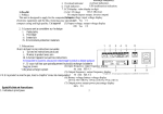
Mains i ndicator: utility power input indication.
2. Bypass indicator: utility power output indication.
3. Output indicator: inverter output indicator.
1
i ndicate battery will
discharge completely.
overload indication.
5. Overload indicator:
UPS malfunction indication.
6. Fault indicator:
7. LCD display: value display in digit
BAT: OK (low)
(1).AC: IN (loss)
No output (bypass output, inverter output)
(2).Input voltage: input voltage display
220 Vac # 1
(3).Output voltage: output voltage display
220 Vac # 2
4. Battery capacity indicator:
(4).Input frequency: input frequency display
50 (60) HZ # 3
(5).Output frequency: output frequency display
50 (60) HZ # 4
(6).Battery voltage:battery voltage display
220 Vdc #5(4~30KVA) 110Vdc (2.3KVA) 55Vdc (1KVA)
(7).Output power:output power percentage display
1 00% # 6
2
8. Page up and down button: turning pages by pressing the
button to display UPS starus.
9. UPS power on-off button
(1) Press the UPS power on-off button, the inverter inside
the inverter starts to work. About 20 seconds later,
the unit output is provided by inverter instead of by
utility power with pure AC output in sine waveform.
(2) Press the UPS power on-off button again to turn off
the inverter,with the unit being powered by utility
power in bypass mode.
13. Power supply switch: taking control of input, output
and battery power supply.
14. Distribution terminals port.
15. Movable wheels:
4 wheels are available
in the bottom.
Figure3: Rear panel outlook
Figure2:Front outlook
10. Ventilation intake.
11. Distribution wire intake.
12. DB-9 communication interface socket: standard interface
set between the unit and computer.
3
3.Setting up
(1). Transportation
1. Firstly disconnecting all line.
2. Handle carefully.
3. DO NOT turn the unit upside down.
(2). Placement
1. DO NOT put the unit on the uneven surface.
2. Allow adequate ventilation all around the unit so that
heat from the unit can properly disperse. DO NOT
install the unit in an air-blocked area.
3. Avoid direct sunshine, rain or moist air.
4. Keep away from fire or high temperature.
5. DO NOT place articles on the top of unit.
6. Environment temperature: 0 °C-V40'C.
4. Installation
(1). Input
1.Prohibit to employ normal plug
for connection, because
the maximum current
of normal plug is 15A,
which will lead to
overload and damage
to the unit.
2. Connect the unit input
with 220V.
3. Wire connection
a. Unscrew the nail as shown in figure 4
b. Open the lid, and distribution terminal port under the
power switch can be presented as shownin figure 5.
4. After completion of wire connection, put the lid back.
5. Connect the input wire, output wire and battery wire
from distribution wire intake to the terminal.
6. Do NOT reverse the power polarity. Judgment of
power polarity is as follows:
(1). Hot line (L): 220V
(2). Neutral (L): 220V to hotline, and 0.5-2 V to ground
line.
(3). Ground (G): locate the real ground point
figure 5: UPS distribution terminal block
If the voltage tolerance between neutral and ground
is more than 5V, reinstall to make sure sound grounding
and safety operation.
5. The relationship between input current rating and input
4.
Figure 4
6
(2). Precaution:
wire diameter is shown in below timetable
(1). Make sure the right connection. Adhere to the above-
3 mm (soft wire)
Terminal pec.
5.5~6
34A
5.5 mm (soft wire)
5.5-6
(2). Output
45 A
5.5 mm (soft wire)
10 KVA
56A
8.5 mm (soft wire)
5.5~6
8.5~9
15 KVA
80A
8.5 mm (soft wire)
8.5~9
Model
Inpu tmax. urrent
Input wire spec
2, 3 KVA
17 A
4, 6 KVA
8 KVA
20 KVA
10A
12 mm (soft wire)
1 012
30 KVA
168 A
18 mm (soft wire)
1 215
mentioned procedure.
1. Refer to figure 7 for wire connection
6. Make sure the wire and other relevant component is well
qualified to avoid unexpected event such as short circuit.
7. Turning off the unit when connecting wire to make sure
figure 7
safety.
8. Turn off the power supply when carry out connection.
9. When connect wire to distribution terminal, DO NOT
2. The wire diameter is according to the load current, DO
NOT employ thin wire.
share the switch with other equipment as shown in
3. Do not allow for short circuit or overload.
figure 6
4. Relationship between current rating and wire diameter
7. In 3 phase and 4 wire systems, make sure the voltage
is shown in below timetable.
between neutral line and three phase
Model
Input max. current
Input wire spec.
Terminal pee.
R, S, T is close to 220V.
2, 3 KVA
II A
2.5 mm (soft wire)
4, 6 KVA
34A
5.5 mm (soft wire)
5.5~6
5.5~6
8 KVA
45 A
5.5 mm (soft wire)
5.5~6
10 KVA
56A
8.5 mm (soft wire)
8.5~9
15 KVA
80 A
8.5 mm (soft wire)
8.5~9
line, and UPS'-GND to ground
20 KVA
110A
12 mm (soft wire)
1 012
object.
30 KVA
168 A
18 mm (soft wire)
1 215
8. If you purchase a unit with 110V
input voltage, make sure to connect
UPS line L to hot line, N to neutral
5. The ground line is only for reference point to the unit.
If any disturbance resulting from ground wire connection
Figure 6: UPS input terminal wire
7
or whatever, consult professional.
8
6. User should provide sound grounding system.
(2). Startup procedure for first time
7. Pinpoint the location close to ground object or the
After making sure the above-mentioned procedure, start up
starting point in the power distribution plate for ground
connection. Refer to figure 8.
the unit by following steps:
1. Turn on the non-fuse breaker in the real panel, meanwhile
the mains indicator and bypass indicator in the front
panel will be on as shown below figure.
2. Press the UPS power on-off button, as shown below.
Mains indicator and bypass indicator in the front panel
will be on continuously, and LCD shows that mains is
normal, battery is normal, and utility power goes through
figure 8: input single-phase 220V and 110V distribution wire system
bypass circuit.
Attention:
Operate according to the input voltage system.
5. Operating procedure
(1). Preparation before startup
Pay attention to the following steps before start the unit to
make sure the normal operation of the unit.
1. Make sure
power switches are in OFF position.
all
3. After 20 seconds, mains indicator in front panel is on,
bypass indicator is off, output indicator is on. LCD
shows that AC is in, BAT is normal, and output is from
inverter.
2. Check the setup location again.
3. Make sure the wire is tight.
4. No connection to load.
5. Make sure the input voltage is in accordance with what
the unit requires (220V± 10%).
9
10
4. Cut off the unit input power, and mains indicator is off.
LCD shows AC loss, BAT OK, and output is provided by
inverter as below figure shows. Buzzer alarms every 4
seconds, and battery capacity indicator flashes, which
indicates the unit is powered by batteries. (UPS continuously
alarms for 90 seconds, then stop automatically, until the
battery discharge entirely, UPS alarms every second).
2. If DO NOT use the unit for more than 30 days, follow the
first time startup procedure and run the UPS for 24 hours
to make sure the battery capacity is full to extend battery
life.
Fault handling
(1). Mea ning of symbol:
Bz
• ["°,1 ~
c~
on off flash buzzer buzzer buzzer buzzer
keep
every
every
alarming
5. Recover UPS input, mains indicator will be on. Press page
up and down button to make sure all display value right,
and then first start up procedure is completed. After confirm
the output voltage is up to requirement, connect the load
to the unit output terminal.
4 sec
1 sec
no alarm
(2). Unit operation status display and fault handling
Detect the unit operation status with reference to panel
indicator, LCD display value and buzzer alarm. If the
unit works abnormally, handle with panel display
information
1. LCD display as below shown
6. Connect to load. Press the Page up and down button to
make sure that the percentage of output power is no more
than 100%
(3). Daily procedure for startup and turndown
1. For daily turndown of the unit, press the power on-off
button to shut down the unit. And now the unit is in the
status of bypass, the output is powered by utility power
and the batteries are being charged.
2. For daily startup of the unit, press the power on-off button
to start up the unit.
(4). Operating procedure for long time not using UPS
1. If DO NOT use the unit for more than 10 days, press all
UPS button off, then shut down the unit.
a. Unit operation status:
Mains power supply ok, UPS run normally in full load
b. No fault
2. LCD display as below shown
a. Unit operation status:
Mains power supply ok, UPS run normally with battery
capacity more than 90%.
b. No fault
3. LCD display as below shown
a. Unit operation status:
Unit is powered by mains with 200Vac, and UPS work
normally.
b. No fault
4. LCD display as below shown
a. Unit operation status:
Mains power supply ok, and supplied under bypass mode.
b. Refer to fault handling procedure fault handling
procedure figure 10.
6. LCD display as below shown
a. Unit operation status:
Mains power supply ok, UPS run abnormally with 125%
load, while overload indicator is on, and buzzer alarms.
b. Handling
Remove part of load to make the output power percentage
less than 100%. If nothing goes change, get engineer
for help. If remains unchanged after removing part of
the load, refer to fault handling procedure figure 11.
7 LCD display as below shown
a. UPS operation status:
Mains power supply ok, UPS run normally with low
battery capacity.
b. Handling:
Charger
the statue of malfunction, replace charger.
is in
5. LCD display as below shown
a. Unit operation status:
Mains power supply ok,UPS is in the status of malfunction,
then powered by mains instead of unit.
b. Handling
Refer to fault handling procedure figure 12.
8. LCD display as below shown
a. UPS operation status:
Probably mains power supply is in the event of outage
and battery will discharge completely, UPS will be off
automatically.
a. Unit operation status:
Mains power supply is off, and is powered by batteries
with full load. Buzzer alarms every 4 seconds, and battery
capacity indicator flashes every 4 seconds (after 90 seconds,
buzzer and indicator stop alarming and flashing)
b. Handling
If the mains power supply is off, remove part of load
to increase usage time. And refer to fault handling
procedure figure 9.
9. LCD display as below shown
a. UPS operation status:
Mains power supply is off, and is powered by batteries.
Batteries will be discharged completely very soon,
buzzer alarms every second, and battery capacity
indicator flashes every second
b. Handling
UPS will be off automatically, complete your job
quickly and save files.
1 O.LCD display as below shown
b. Handling
Upon recovery of mains power supply, UPS will restart
automatically.
If mains power supply will be in the situation of outage
for more than 6 hours, turn off all UPS button.
figure 10: fault handling chart
figure 12: faulting handling procedure
Principle
(1). Unit systematic block diagram as shown below
(3). Operation in the event of outage
As shown in the below figure, output is powered by
built-in batteries through inverter, static switch and
filter for better sine waveform to guarantee continuous
power supply.
figure 13: unit systematic diagram
(2). Normal operation
When UPS run normally, high frequency harmonics
coming from mains can be minimimized by filter as
shown in the below figure 14. Some signal will charge
the battery through charger to keep the battery capacity
in full, while other signal go through rectifier and transform
to DC current. Then it will be converted into sine wave
by inverter and sent to the end equipment through static
switch and filter.
(4). Bypass
There are five statuses resulting in bypass
a) Overload.
b) Inverter failure.
c) Within 20 seconds after press the UPS power on-off
button to startup UPS, during which period the UPS
come into operation gradually.
d) During the process when shut up UPS.
e) UPS operate in the status of over temperature inside
the unit.
charger
Battery group
Figure 16: Operation in the event of bypass
20
(5). Battery and charging
1. Set the power switch on the rear panel to ON position
to charge the battery. After 10 hours, the battery can be
charged up to 90 % full capacity.
2. Battery supply time is relevant to the load, as below
figurehows.
battery you employ is normal lead-acid battery for automobile
use, check the electrolytic liquid per month. Refill with
steaming water if the level is low.
Attention:
Maximize the life expectancy of the unit by following the
procedure provided in the manual.
8. Communication interface description
Figure 17: battery supply time versus load
3. Get professional to add outside battery if want to extend
backup time.
4. Always maintain the battery in full capacity to extend
battery life expectancy.
5. DO NOT remove the cover except for an engineer.
This manual provides installation and operation of UPS,
subject to the difference of area and other relevant condition.
Consult your supplier for further information.
(6). Daily maintenance
1.Clean the UPS to get rid of dusts timely.
2.Rinse with soft cloth when cleaning.
3.Check all kinds of wire per month.
4.Keep all ventilation intakes well ventilated.
The built-in battery provided is free of maintenance. If the
21
(1 ). Most of computer system is equipped with UPS in case
of power outage, so communication interface is provided to
connect with computer for monitoring power supply.
(2). UPS status can be displayed by connecting computer
with DB9 communication interface in the rear panel on the
condition that the operating system such as DOS, WINDOW S3.1,
WINDOWS95, WINDOWS/NT, NOVELL should be employed.
Alarm signal can be sent in the event of outage. Upon the set
time, the unit can be off automatically following set procedure.
Upon recovery of utility power, the unit start to operate, and
the system start to run.
(3). There are two kinds of communication interface to be
selected. One is only for providing UPS status, suitable for
PC usage, while the other can offer detailed information for
usage in the computer network, work station, monitoring
system and etc. Standardized UPS only offer the first type of
interface for personal computer, and the expense of software
is on users' account.
1. For the first kind of computer interface: only the
function of outage of utility power, low battery alarm
and auto shutdown is offered.
2. For the second kind of computer interface: RS232
22
communication port is employed to connect computer
9.Property timetable
for continuous transmitting files. The information
provided includes input voltage value, output voltage
Capacity
value, output frequency, input frequency, battery voltage
The pin signal of DB9 is as bellows:
C input
Pin l : unit failure
Pin2: utility power outage
Pin3: inverter power on
Pin5: battery will discharge completely
Pin9: RS232 TXD
4K
6K
8K
15K 20K 30K
220VAC/380VAC 25%
Frequency
50 (60) Hz +/-5
Phase
Single phase/ three phase
Voltage
220 VAC
Frequency
50 (60) Hz
+/-1
stability
+/-1 % in the event of outage
C
Waveform
Sine wave
out-
Factor
put
THD
0.7 (lag behind)
1 0.8 (lag behind)
<0.3 (linear load)
Transient response
Voltage
4%, (100%) load
48VDC
96VDC
192VDC
Mode
Sealed lead acid battery, free of maintenance
Batt-er
Supply time
Refer to figure 17.
y
Charging time
During 8 to 10 hours, up to 90% full capacity
Efficiency
>85%
Transfer time in the
event of outage
23
10K
Frequency
Pin6: turn off unit or RS232 RXD line
Pin8: inverter output
3K
Voltage stability
Pin4: joint ground of Pin l, 2, 3, 5, 8
Pin7: grounding of Pin6
2K
Voltage
value, load percentage, UPS inside temperature and etc.
(4). Outlook of DB9 is shown below figure 18.
1K
Zero
24
25
26
11.
Packing list
Series
number
Content
Unit
Number
1
UPS
Piece
1
2
3
UPS user manual
Piece
1
Qualification certificate
Piece
1
4
Upsilon 2000 intelligent monitor
Piece
1
Piece
1
laser disc
5
Computer terminal connection cable