1
1 Introduction
1. 1 Description of Commonly Used Symbols
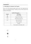
Some or all of the following symbols may be used in this manual and may
appear in your application process. Therefore, all users should read the
form carefully and thoroughly.
Symbol
Symbol & Description
Description
Caution, danger
Danger electric shock
Alternating current (AC)
Direct current (DC)
Protective ground
Recycle
Do not dispose with ordinary trash
1
1 Introduction
1. 2 Safety Instructions
1. Read this manual carefully and thoroughly before operation the UPS and
save this manual properly for future reference.
2. Do not tear up or shatter the alarm table on the UPS and pay attention to
it.
3. Please do not overload the UPS.
4. The UPS contains large capacity batteries. The case of the UPS must not
be opened by untrained personnel. Otherwise, it may cause electric
shock.
5. Do not short the positive and negative electrodes of battery. Otherwise, it
may cause electric shock or fire.
6. Do not plunge or insert any objects into the air vents and other inlets.
7. Do not store or use the device in the following environment:
Where there is inflammable gas, corrosive agents or heavy dust
Where the temperature is very high or low (above 40℃ or below 0℃)
or the humidity is very high(more than 90%)
Under direct sunlight or close to heating facilities
Place of strong vibrations
8. In the event of fire occurring in the vicinity, please use dry powder fire
extinguishers .The use of liquid fire extinguishing agents may cause
electric shock.
2
2 Product Description
The HT-series is an on-line uninterruptible power supply device
incorporating double-converter technology with single-phase input and
single-phase output. It offers the high quality power supply with the
greatest degree of availability and reliability. The 1-3kVA of HT series is
compact and convenient for users, especially for the basic equipments in
some areas such as: finance, communication, government, traffic,
manufacture, education and so on.
2. 1 System Type and Configuration
There are two types of UPS according to the battery configuration: standard
type and long backup time type, each available in the following ratings:
1kVA, 2kVA and 3kVA UPS.
Table 2-1 UPS types and configurations
Type
Model
Remark
With a 1A internal charger and 3 build-in batteries
1kVA
HT1K
2kVA
HT2K
3kVA
HT3K
Long
1kVAL
HT1KL
With a 7A internal charger and external battery slot.
Backup
2kVAL
HT2KL
With a 7A internal charger and external battery slot.
Time
3kVAL
HT3KL
With a 7A internal charger and external battery slot.
Standard
of 12V/ 7AH
With a 1A internal charger and 6 build-in batteries
of
12V/ 7AH
With a 1A internal charger and 8 build-in batteries
of 12V/ 7AH
Note: “L” model means Long Backup Time.
3
2 Product Description
2. 2 The Appearance of the UPS
Figure 2-1 The rear panel of HT1KS
S
Figure 2-2 The rear panel of T2KL-ST3KL
* The picture for back panel is just for reference, it subjects to change on
customer’s requirement, please refer to the real subject.
4
2
Product
Description
Note:The appearances above are examples with the long backup time, the
corresponding standard type is without the “External Battery slot”.
2. 3 Operating Principle
Figure 2-3 The UPS operating principle
1. Input filter: it filters the input and provides clean AC power to the UPS.
2. AC/DC converter: In Normal mode, it converts the AC input power to
regulated DC power, and raises the regulated DC voltage for DC/AC
converter.
3. DC/DC converter: Raises the DC Voltage from the battery system to the
optimum operating voltage for the inverter when the UPS operates in
Battery mode.
4. DC/AC inverter: In Normal mode, it utilizes the DC output of the
AC/DC converter and inverts it into precise, regulated sine wave AC
5
power. In Battery mode, it receives energy from the battery through the
DC/DC converter.
2 Product Description
5. Bypass: It is very important in the UPS system. In the event of a UPS
fault that will not lead to UPS shutdown, the load will be automatically
transferred to the bypass. Meanwhile, the LED indicators will indicate
the fault type, and the fault information will be reported through the
communication ports.
6. Charger: The charger of standard UPS provides 1A charging current; and
long backup time provided 7A charging current.
7. Battery: Sealed maintenance-free lead –acid battery can be used as the
DC source of the UPS.
8. Output filter: It filters the output and provides clean AC power to the
load.
6
3 Installation
3. 1 Unpacking Inspection
1. Open the packing box of UPS and take it out, visually examine the unit
for transit damage.
2. Check against the accessory lists that the accessories of the UPS are
present. (Refer to Table 9-1).
3. Make sure the model is what you wanted from the nameplate on the rear
panel
4. If the UPS arrives damaged, or there is any missing accessory or other
question above, please contact the distributor immediately.
3. 2 Installation Notes
1. When locating the UPS, make sure there is no hazardous objects such as
water, inflammable gas, corrosive agents and so on around the UPS, and
that the installation environment meets the specifications.
2. The UPS should not be placed on a side. The air inlet port at the front
panel and the outlet port on the rear panel and two side panels should not
be blocked so as to ensure good ventilation.
3. In case if the UPS is unpacked, installed and used at very low
temperatures, condensations of water drops may appear. It is necessary
to wait until the UPS fully dried inside out before proceeding to
installation and use. Otherwise, they may be a risk of electric shock.
4. Place the UPS near the utility power source outlet which supplies power
to the UPS. In any emergency, switch off the main input socket, cut off
the battery voltage input. All power sockets must be connected with
ground protection.
7
3 Installation
3. 3 Cable Connection
3.3.1 Connecting Input and Output Cables
1. Input cable connection
If the UPS is connected via the power cable, please use a proper socket
with over current protection, and pay attention to the capacity of the
socket: over 10A for HT1K(S), over 16A for HT2K(S) and HT3K(S). A
side of input wiring has been fixed with the UPS, and the other side is
just need to plug into the input socket. The wiring configuration is shown
in the following diagram.
Figure 3-1 Connection Method of Input
2. Output cable connection
The output of HT1K(S)/ HT2K(S)/ HT3K(S) all available to uses sockets.
The total output power shall not exceed 1kVA/0.8kW, 2kVA/1.6 kW,
3kVA/2.4 kW. Simply plug the load power cable to the output sockets of
8
UPS to complete connection as shown in the following diagram.
3 Installation
Figure 3-2 Connection method of output
3.3.2 Operation Procedure of External Battery for Long Backup
Time UPS
The battery connection procedure is very important for long backup model.
Any incompliance may result in the risk of electric shock. Therefore, the
following steps must be strictly complied with.
1. First connect in series the batteries of the pack to ensure proper battery
voltage that HT1KS for 36VDC, HT2KS for 72VDC, HT3KS for
96VDC.
2. Take out the battery cable delivered with the UPS, one end of the
external battery cable is a plug for connecting the UPS, the other end has
3 open wires for connecting the battery pack.
3. Connect the external battery cable to the battery terminal (DO NOT
connect the battery socket of the UPS first. Otherwise, it may cause
electric shock). Connect the red wire to the “+” terminal of the battery.
The black wire is connected to the “-” terminal of the battery. The
9
green/yellow wire is grounded for protection purpose.
4. Connect the plug of the external battery cable to the external battery slot
on the rear panel of the UPS to complete the connection procedure.
3 Installation
Figure 3-3 Battery connection diagram for Long Backup time models
Note: The length of the external battery cable is 1.6 m, If users need a longer one,
please consult the distributor. There is a limit to the length of the external
battery cable to ensure normal operation of the UPS.
3.3.3 Connecting Communication Cable
1. Computer interface
10
3 Installation
Computer interface: The type of signals is provided by the UPS to
communicate with a host computer through
communication cable included in the standard
accessory, User can use special monitor software
UPSilon in the standard accessory to monitor the UPS
through the port.
2. Alternative connection of communication
Intelligent Slot: It is designed for installing the dry contact card, SNMP
card and 485 card. You can choose for one of them to
installed
a-dry contact card: You can utilize monitor function of dry contact to
manage the power supply directly.
b-SNMP: It enables you monitor the UPS remotely through Internet.
c -485: Central monitor card.
Note: Please remove the cover board of the intelligent slot before any card is
installed.
11
12
4 Operation (LED model)
4. 1 Introduction of Display Panel
1. ON button:
Pressing the ON button more than 1 second, the UPS system is turned on.
2. OFF button:
By pressing this button more than 1 second turns off the UPS system
whenever the UPS run under the normal mode/battery mode.
3. Function button
The Function button provides the following functions:
1) Battery self- diagnosis: When the UPS ran in normal mode, pressing this
button more than 2 seconds (buzzer beeps twice) can start the battery
self-diagnosis.
2) Silence function in battery/bypass mode
In battery/bypass mode, when the buzzer beeps, pressing and holding the
function button for more than 2 seconds (buzzer beeps two times) can
silence the buzzer. Press the button for more than 2 seconds (buzzer
beeps twice) again to resume the alarm function
Note: The alarm silencing function of the Function button is valid only in
battery mode, and invalid for any other UPS alarm.
4. LED indicators
The LEDs contains Fault indicator, Load/battery capacity indicator, Bypass
indicator, utility power indicator, Inverter indicator, Battery indicator.
13
4 Operation (LED model)
Table 4-1 Description of indicators
No.
Color
Indicator
1#
Red
Fault indicator
2#
Orange
Load/battery capacity indicator
3#
Green
Load/battery capacity indicator
4#
Green
Load/battery capacity indicator
5#
Green
Load/battery capacity indicator
6#
Green
Load/battery capacity indicator
7#
Orange
Bypass indicator
8#
Green
Utility power indicator
9#
Green
Inverter indicator
10#
Orange
Battery indicator
Description
When the indicator on, it shows that
the UPS in abnormal condition.
Show the capacity of load/battery:
1.Indicate the percentage of the load
capacity in normal mode and bypass
mode
2. Indicate the battery capacity level in
battery mode.
When the indicator on, it shows that
the loading current is supplied from the
utility power directly
When the indicator on, it shows that
the utility power is normal.
When the indicator on, it shows that
the load current is supplied from utility
power or battery via the inverter.
When the indicator on, it shows that
the load current is supplied from
battery via the inverter.
4. 2 Operation Mode
4.2.1 Normal mode
In the normal mode, the display on the front panel is shown in the
following diagram. The utility power indicator and the Inverter indicator
are turned on.
The load/battery capacity indicator will be turned on in accordance with the
load capacity connected.
1. If the utility power indicator blinks, it indicates that there are problems
with reversed polarity (L, N) of site wiring or disconnect with ground
that may result in shock hazard. UPS is still working in normal mode. If
the battery indicator is turned on at the same time, it shows that the
14
4 Operation (LED model)
voltage or frequency of the utility power is out of the normal input
range of the UPS. The UPS works in battery mode.
Figure 4-2 Normal Mode
2. If output overloaded, the load level indicators will be turned on and
alarm will beep every second. You should get rid of some unnecessary
loads one by one to decrease the loads connected to the UPS less than
100% capacity of the UPS.
3. If the battery indicator blinks, it indicates that no battery is connected to
the UPS or battery voltage is too low. You should check if battery is
properly connected to the UPS, and press function button more than 2
seconds to start the battery self-diagnosis. If the connection between
battery and UPS is confirmed without any problem, it may be due to the
defect or aging of the battery, please refer to the “troubleshooting” in
chapter 7 to solve the problem accordingly.
Note:Connection to the power generator should be made according to the
following steps:
Activate the power generator and wait until the operation is stable before
connecting the output of the power generator to the UPS (be sure that the
UPS is in idle mode). Then, turn on the UPS according to the startup
procedure. After the UPS is turned on, the loads are connected one by one.
15
4 Operation (LED model)
It recommended that the capacity of the AC generator chosen should double
that of the UPS.
4.2.2 Battery mode
In battery mode the display on the front panel is shown in the following
diagram. The battery indicator and the inverter indicator are turned on. If
the utility power indicator blinks at the same time, it shows that the utility
power is abnormal. The load/battery capacity indicators will be turned on in
accordance with the battery capacity. Please note that the load/battery
capacity indicator in normal mode will indicate the battery capacity in
battery mode.
1. When the UPS is running in battery mode, the alarm will beep every 4
seconds. If the “Function” key is pressed for more than 2 seconds, the
alarm will not beep (silence function). Press the “Function” key more
than 2 seconds again to resume the alarm function.
Figure 4-3 Battery Mode
2. When the battery capacity decreases, the number of load/battery capacity
indicators turned on will decrease. If the battery voltage drops to the
pre-alarm level, the alarm will beep every second to remind the user of
insufficient battery capacity.
16
4 Operation (LED model)
4.2.3 Bypass mode
When operating in bypass mode set up through UPSilon software, the
display on the front panel is show in the following diagram. The utility
power indicator and the bypass indicator are turn on. The load/battery
capacity indicator will be turned on in accordance with the load capacity
connected.
1. If the utility power indicator blinks, it shows that the voltage or
frequency of the utility power is out of the input range of the UPS or
there are problems with reversed polarity (L/N) of site wiring or
disconnect to the ground for protection.
2. When operating in bypass mode, the UPS beeps every 2 minutes, If the
“Function” key is pressed for more than 2 seconds, the alarm will not
beep(silence function). Press the “Function” key more than 2 seconds
again to resume the alarm function.
Notes: When operating in bypass mode, the backup function of the UPS is not
available and the power used by the load is directly from the utility
power via internal EMI filter.
Figure 4-4 Bypass Mode
17
4 Operation (LED model)
4. 3 Operating Instructions
4.3.1 Turning On and Completely Powering Down the UPS
Note: The battery is fully charged before delivery. However, storage and
transportation will inevitably cause some charge loss. Therefore, it
is advisable to charge the battery for 10 hours before using it, so as
to ensure adequate battery capacity.
1. Turning on the UPS
The operation of turning on the UPS contains: turning on with utility power
and turning on without utility power.
1) Turning on with utility power:
Connect the mains input to the UPS, press the ON button more than one
second, UPS starts to turn on. At this point, the UPS begins to conduct
self-diagnosis, with the load/battery capacity indicators on the front panel
turned on and then off one after another. A few seconds later, the UPS
will begin to operate in Normal mode; meanwhile, the utility power
indicator, inverter indicators will turn on. If the utility power is abnormal,
the UPS will work in battery mode.
2) Turning on without utility power:
With no mains input feeding to the UPS, press the ON button more than
one second, ups start to turn on. In the power on process, the UPS has the
same operation as if it is connected to utility power except that the utility
power indicator is not turned on and the battery indicator is turned on
instead.
2. Powering down the UPS
The operation of powering down the UPS contains: turning off ups in
normal mode, turning off ups in battery mode
18
4 Operation (LED model)
1) Completely power down the UPS from Normal mode
Hold and press the OFF button persistently for more than 1 second to
power off the UPS. If it bas been set up to work in bypass mode by
software, the bypass indicator will be turn on to indicate that the UPS is
working in bypass mode. In order to cut off the output from the UPS,
simply cut off the utility power supply. Finally, not any display is shown
on the front panel and no output is available from the UPS outlets,
system completely power down.
2) Completely power down the UPS from Battery mode
Press the “ON/OFF” button persistently for more than 1 second to power
off the UPS. When being powered off, the UPS will start self-diagnosis
and all the load/battery capacity indicators will be turn on and off one
after another. Finally, not any display is shown on the front panel and no
voltage output is available from the UPS outlets, system completely
power down.
4.3.2 Conducting Battery self-diagnosis
In UPS operation, users can manually initiate battery self-diagnosis to
check the battery conditions. There are two methods to initiate the battery
self-diagnosis:
1. Through the function button
In normal mode, press and hold the function for more than 2 seconds
until the buzzer beeps twice. At this point the indicators (LED7~10) will
blink cyclically, indicating the UPS has worked in battery mode and the
battery self-diagnosis has started. The battery self-diagnosis will last for
10 seconds default. In the event of a battery fault during battery
self-diagnosis, the UPS will transfer to normal mode automatically.
2. Through the monitor software
Users can also initiate battery self-diagnosis through the background
19
monitoring software
4 Operation (LED model)
4.3.3 Audible alarm and LED indication of UPS operating status and
faults
No.
Operating status
1
0%--25%Load
2
3
Normal
mode
4
6
7
9
10
2
#
Battery
mode
3
#
LED indicators
4 5 6 7 8
# # # # #
9
#
10
#
Audible alarm
●
● ●
none
26%--50% Load
● ●
● ●
none
51%--75% Load
● ● ●
● ●
none
● ● ● ●
● ●
none
● ● ● ● ●
● ●
76%--100% Load
5
8
1
#
101%--105%
Load
0~25%
battery capacity
26~50%
battery capacity
51~75%
battery capacity
76~100%
battery capacity
100%
battery capacity
●
● ●
● ●
● ●
● ● ●
● ●
● ● ● ●
● ●
● ● ● ● ●
● ●
11
Bypass mode
↑
↑
12
Overloaded in bypass
mode, pre-alarm
● ● ● ● ● ● ↑
13
Utility power abnormal
↑
14
Overload
in
Battery
mode, pre-alarm
● ●
15
Overloaded in Normal
mode, pre-alarm
● ●
16
Overheating fault
●
17
Inverter fault
●
↑
↑
↑
↑
↑
Beep once
every 2 min.
Beep twice
every sec
● ● ↑
● ↑
★ ↑
↑
● ●
● ●
●
20
● ↑
↑
↑
↑
Beep
once
every sec
Beep
once
every sec
Beep
once
every 4 sec.
Beep
once
every 4 sec.
Beep
once
every 4 sec.
Beep
once
every 4 sec.
↑
Beep once
every sec
Beep once
every sec
Sustained
beep
Sustained
beep
4 Operation (LED model)
LED indicators
No.
Operating status
1
#
2
#
18
BUS voltage fault
●
19
Over voltage of charger
output
●
20
Output short circuit
● ●
21
Overload fault
● ●
22
23
Battery
voltage
abnormal
Reversed polarity (L, N)
of input wiring or
disconnected
with
ground.
↑
3
#
4
#
5
#
6
#
●
●
7
#
8
#
↑
↑
↑
↑
↑
↑
●
↑
↑
↑
↑
● ↑
●
25
Fan failure
● ●
↑
★ ↑
★
↑
↑
Beep once
every 2 min.
★
● ↑
LED indictor description: ●:O n
conditions
21
↑
Audible alarm
Sustained
beep
Sustained
beep
Sustained
beep
Sustained
beep
↑
●
↑
Charger or battery fault
10
#
↑
●
↑
24
9
#
↑
↑
Beep once
every sec
Beep every
sec
★:Flash ↑:Depending on other
5 Operation (LCD model)
5.1 Operation Display Panel
1. ON button:
Pressing the ON button more than 1 second (buzzer beeps once), the UPS
system is turned on.
2. OFF button:
By pressing this button more than 1 second (buzzer beeps once) turns off
the UPS system whenever the UPS run under the normal mode/battery
mode.
3. Function button
The Function button provides the following functions:
a) Battery self- diagnosis: When the UPS ran in normal mode, pressing this
button more than 2 seconds (buzzer beeps twice) can start the battery
self-diagnosis.
b) Silence function in battery/bypass mode
In battery/bypass mode, when the buzzer beeps, pressing and holding the
function button for more than 2 seconds (buzzer beeps two times) can
silence the buzzer. Press the button for more than 2 seconds (buzzer
beeps twice) again to resume the alarm function
22
5 Operation (LCD model)
c) LCD display screen switch
Pressing the function button for more than 1 seconds and less than 2
seconds (buzzer beeps once) to switch LCD display screen
4. LED indicators
The LED indicators contains, Bypass indicator, utility power indicator,
Inverter indicator, Battery indicator. The definition of each indicator is the
same as LED panel (refer to table 4-1).
5.2 Operation Mode
UPS Operation Mode contains normal mode, battery mode and bypass
mode. Under the three modes, the page showing output voltage and output
frequency is the main display page. If users need more information about
UPS, Pressing the function button can initiate display screen switch. If the
current page is not the main page, UPS will automatically switch back the
main page after 30 seconds. In order to extend the LCD usage life, the
backlight will turn off after 1 minute without any switch operation. At this
point, Users just need to touch any button briefly to turn on the backlight.
5.2.1
Normal mode
When operating in the normal mode, the display of main page on the front
panel is shown as the figure 5-2. The utility power indicator and the
Inverter indicator are turned on. Load information area shows load value,
and the battery level area indicates dynamically when the battery is not
fully charged (the battery level icons lit one after another circularly). When
the battery is fully charged, all the level icons are turned on.
23
5 Operation (LCD model)
1) If the utility power indicator blinks, it indicates that there are problems
with reversed polarity (L, N) of site wiring or disconnect with ground.
UPS is still working in normal mode. If the battery indicator is turned on
at the same time, it shows that the voltage or frequency of the utility
power is out of the normal input range of the UPS. The UPS works in
battery mode.
Figure 5-2 Normal Mode
2) If load is more than 100 percent, the buzzer beeps every second,
meanwhile, the warning icon blinks every second too, reminding that
UPS is overloaded. You should get rid of some unnecessary loads one by
one to decrease the loads until the alarm clear
3) If the battery indicator blinks, it indicates that no battery is connected to
the UPS or battery voltage is too low. You should check if battery is
properly connected to the UPS, and press function button more than 2
seconds to start the battery self-diagnosis. If the connection between
battery and UPS is confirmed without any problem, it may be due to the
defect or aging of the battery, please refer to the “troubleshooting” in
24
chapter 7 to solve the problem accordingly.
4) The other four display pages are load percent page, actual load page,
input information page and the maximum temperature page.
5 Operation (LCD model)
Note:Connection to the power generator should be made according to the
following steps:
Activate the power generator and wait until the operation is stable before
connecting the output of the power generator to the UPS (be sure that the
UPS is in idle mode). Then, turn on the UPS according to the startup
procedure. After the UPS is turned on, the loads are connected one by one.
It recommended that the capacity of the AC generator chosen should double
that of the UPS.
5.2.2 Battery Mode
When operating in the battery mode, the display of main page on the front
panel is shown as the figure 5-3. The battery indicator and the Inverter
indicator are turned on. If the utility power indicator blinks at the same time,
it shows that the utility power is abnormal. Load information area shows
load value, and bat level area shows current battery capacity.
1) When the UPS is running in battery mode, the alarm will beep every 4
seconds. If the “Function” key is pressed for more than 2 seconds, the
alarm will not beep (silence function). Press the “Function” key more
than 2 seconds again to resume the alarm function.
25
Figure 5-3 Battery Mode
5 Operation (LCD model)
2) When the battery capacity decreases, the number of battery capacity
indicators turned on will decrease. If the battery voltage drops to the
pre-alarm level, the alarm will beep every second to remind the user of
insufficient battery capacity.
3) The other four display pages are load percent page, actual load page,
battery information page and the maximum temperature page.
5.2.3 Bypass Mode
When operating in bypass mode set up through UPSilon software, the
display on the front panel is shown as the figure 5-4, the utility power
indicator and the bypass indicator are turned on. Load information area
shows load value, and the battery level area indicates dynamically when the
battery is not fully charged (the battery level icons lit one after another
circularly). When the battery is fully charged, all the level icons are turned
on.
1) When operating in bypass mode, the UPS beeps every 2 minutes. If the
“Function” key is pressed for more than 2 seconds, the alarm will not
beep (silence function). Press the “Function” key more than 2 seconds
again to resume the alarm function.
2) If the utility power indicator blinks, it shows that the voltage or
frequency of the utility power is out of the input range of the UPS or
there are problems with reversed polarity (L/N) of site wiring or
disconnect to the ground for protection.
3) The other four display pages are load percent page, actual load page,
input information page and the maximum temperature page.
26
Notes: When operating in bypass mode, the backup function of the UPS is not
available and the power used by the load is directly from the utility
power via internal EMI filter.
5 Operation (LCD model)
Figure 5-4 Bypass Mode
5.2.4 LCD indication of UPS alarm status and faults
In the event of an UPS fault, UPS enters fault operation mode, at this point,
the fault icon turns on consistently, the buzzer beeps continuously and the
data information area shows current fault code (refer to table 7-2), the
display on the front panel is shown as the figure 5-5, users can switch to
output page by pressing function button.
27
Figure 5-5 Fault display
When a warning occurred, the fault icon blinks every second, and users can
switch to the alarm display page shown as the figure 5-6 to check the
warning code.
5 Operation (LCD model)
Figure 5-6 Alarm display
5.3 Operating Instructions
5.3.1 UPS ON/OFF Operation
Note: The battery is fully charged before delivery. However, storage and
transportation will inevitably cause some charge loss. Therefore, it
is advisable to charge the battery for 10 hours before using it, so as
to ensure adequate battery capacity.
1. Turning on the UPS
The operation of turning on the UPS contains: turning on with utility power
and turning on without utility power.
1) Turning on with utility power:
28
Connect the mains input to the UPS, press the ON button more than one
second, UPS starts to turn on. At this point, the LCD begins to conduct
self-diagnosis (all the LCD indicators are turn on about 4 seconds). A
few seconds later, the UPS will begin to operate in Normal mode;
meanwhile, the utility power indicator, inverter indicators will turn on. If
the utility power is abnormal, the UPS will work in battery mode.
5 Operation (LCD model)
2) Turning on without utility power:
With no mains input feed to the UPS, press the ON button more than one
second, ups start to turn on, At this point, the LCD begins to conduct
self-diagnosis (all the LCD indicators are turn on about 4 seconds). A
few seconds later, the battery indicator, inverter indicators will be turn on
to indicate that the UPS is working in battery mode.
2. Powering down the UPS
The operation of powering down the UPS contains: turning off ups in
normal mode, turning off ups in battery mode
1) Completely power down the UPS from Normal mode
Hold and press the OFF button persistently for more than 1 second to
power off the UPS. If it bas been set up to work in bypass mode by
software, the bypass indicator will be turned on to indicate that the UPS
is working in bypass mode. In order to cut off the output from the UPS,
simply cut off the utility power supply. LCD begins to conduct
self-diagnosis (all the LCD indicators are turned on about 4 seconds),a
few seconds later, not any display is shown on the front panel and no
output is available from the UPS outlets, system completely power down.
2) Completely power down the UPS from Battery mode
Press the “OFF” button persistently for more than 1 second to power off
29
the UPS. When being powered off, the LCD will start self-diagnosis (all
the LCD indicators are turn on about 4 seconds), a few seconds later, not
any display is shown on the front panel and no voltage output is available
from the UPS outlets, system completely power down.
5 Operation (LCD model)
5.3.2 Conducting Battery self-diagnosis
In UPS operation, users can manually initiate battery self-diagnosis to
check the battery conditions. There are two methods to initiate the battery
self-diagnosis:
1. Through the function button
In normal mode, press and hold the function for more than 2 seconds
until the buzzer beeps twice. At this point the indicators (LED7~10) will
blink cyclically, indicating the UPS has worked in battery mode and the
battery self-diagnosis has started. The battery self-diagnosis will last for
10 seconds default. In the event of a battery fault during battery
self-diagnosis, the UPS will transfer to normal mode automatically.
2. Through the monitor software
Users can also initiate battery self-diagnosis through the background
monitoring software.
30
6 Maintenance
6.1 Battery Maintenance
The battery is key component of the UPS. The battery life depends on the
ambient temperature, charging and discharging times. High ambient
temperature and deep discharging will shorten the battery life.
1. Sealed maintenance-free lead –acid battery be used in the standard.
When being connected to the utility power whether the UPS has been
turned on or not, the UPS keeps charging the battery and also offers the
protective function of charging and discharging.
2. Keep the ambient temperature between 15℃ and 25℃
3. If the UPS has not been used for a long period, charging is recommended
at the intervals 3 months.
4. Batteries should not be replaced individually.
5. Under normal conditions, the battery life lasts 3 to 5 years. In case if the
battery is found not in good condition, earlier replacement should be
made. The battery should only be replaced by qualified service
personnel.
Note: 1.Prior to battery replacement, the UPS must be turned off and disconnected
from utility power.
2. Metal objects such as rings and watches should be removed.
3. Use the screwdriver with insulated handle. Tools and other metal objects
should not be placed on the battery.
4. Short circuit or reverse connection between the positive and negative
terminal of the battery is strictly forbidden.
31
6 Maintenance
6. 2 Checking UPS function
Every time when conducting field maintenance, please check the regular
function of the UPS, including:
1. Check the operation status of the UPS
If the main voltage is within the specifications, the UPS should operate
in normal mode; if the main voltage is abnormal, the UPS should operate
in battery mode. In both cases, there should be no fault indication.
2. Check the transfer between the UPS operation modes
Disconnect the main input to simulate a mains failure, the UPS should
transfer to battery mode and operate normally; then recover the mains
input, the UPS should transfer to normal mode and operate normally
3. Check the LED indicators of the UPS
During the check processes stated above, check that the LED indication
of the UPS agrees with the UPS operation mode.
32
7 Troubleshooting
In the event of an UPS fault, shoot the trouble according to Table 7-1 or
Table 7-2. If the fault still persists, please contact our customer service
center.
Problem
LED display
The 1# Fault
LED and 6#
LED are on
The1# Fault
LED and 5#
LED are on
The 1# Fault
LED and 4#
LED are on
The 1# Fault
LED and 3#
LED are on
Alarm
Beep
continuously
Possible
cause
Solution
Internal
overheat
Ensure that the UPS is not
overloaded and the ventilation
opening is not blocked and ambient
temperature is not too high. Wait for
10 minutes for the UPS to cool down
before turning it on again. If it does
not work. Please contact the
distributor or service center.
Beep
continuously
Internal fault.
Please contact the distributor or
Service center
Beep
continuously
Internal fault
Please contact the distributor or
Service center
Beep
continuously
Over-charging
Protection
The 1# Fault
LED and 2#
LED are on
Beep
continuously
The
UPS
overloaded or
the load device
The 1# Fault
LED and 2#
LED and 6#
are on
Beep once
every
second
Fan of UPS is
not connected
or fault
33
The charger of the UPS is defective.
Please contact the distributor or
Service center
Check the load and remove the
non-Critical device. Recalculate the
load power and reduce the member
of loads connected to the UPS.
Check whether the load device is
fault
Please contact the distributor or
Service center
The 1# Fault
LED and 2#
LED and 5#
are on
Beep
continuously
The
UPS
output is short
circuited
Turn off the UPS. Remove all loads.
Ensure that the loads are not failed
or the UPS has no internal short
before turn on it again. If failed,
please contact the distributor or
service center
7 Troubleshooting
Problem
LED display
The 1#
LED is
The
battery
is blinks
fault
on.
10#
LED
Possible cause
Solution
The charger of
the UPS is
defective
Please contact the distributor or
Service center
Maybe reversed
polarity (L,N) of
site wiring or
disconnect with
ground.
Please check the polarity of the
neutral wiring and the line wiring,
ensure that The green/yellow wire
connect
protective
ground
properly
Alarm
Beep
once
every
second
The 8# utility
power LED
blinks in
normal mode
The battery has
not been fully
charged
The battery discharge time
diminishes
The
UPS
overloaded
Battery aged
The UPS cannot power on
after pressing the power
on key
The power on
key is pressed
too briefly
The UPS is not
connect
to
battery or the
battery voltage
is too low
34
Keep the UPS connected to utility
power persistently for more than
10 hours to charge the battery
again
Check the load status and remove
the non-critical device
Replace the batteries. Please
contact the distributor to obtain
the replacement components for
battery
Press the power on key
persistently for more than 1
second
Check the connection of the
battery. Turn on the UPS without
load if the battery voltage is low
Internal fault
Please contact the distributor or
Service center
Table 7-1 UPS troubleshooting of LED panel indicator
7 Troubleshooting
Faults
Fault/Warning
code
Possible
cause
Fault icon
Alarm
on
constantly
on
constantly
on
constantly
Beep
continuously
Beep
continuously
Beep
continuously
Internal
fault.
Internal
fault.
Internal
fault.
on
constantly
Beep
continuously
The
UPS
output
is
short
circuited
on
constantly
on
constantly
Beep
continuously
Beep
continuously
Internal
fault.
F07
on
constantly
Beep
continuously
Overload
fault
F08
on
constantly
Beep
continuously
Internal
overheat
F01
F02
F03
F04
F05
F06
35
Internal
fault.
Solution
Please
contact
the
distributor or Service center
Please
contact
the
distributor or Service center
Please
contact
the
distributor or Service center
Turn off the UPS. Remove
all loads. Ensure that the
loads are not failed or the
UPS has no internal short
before turn on it again. If
failed, please contact the
distributor or service center
Please
contact
the
distributor or Service center
Please
contact
the
distributor or Service center
Reduce the member of
loads connected to the
UPS.
Ensure that the UPS is not
overloaded
and
the
ventilation opening is not
blocked
and
ambient
temperature is not too high.
Wait for 10 minutes for the
UPS to cool down before
turning it on again. If it does
not work. Please contact
the distributor or service
center.
F09
on
constantly
Beep
continuously
The
charger of
the UPS is
defective
Please
contact
the
distributor or Service center
A01
Blink once
every
second
Beep once
every
second
Overload
pre-warning
Reduce the member of
loads connected to the
UPS.
7 Troubleshooting
Faults
Fault/Warning
code
A02
A03
A04
A05
A06
Fault icon
Alarm
Blink once
every
second
Blink once
every
second
Blink once
every
second
Blink once
every
second
Beep once
every
second
Beep once
every
second
Blink once
every
second
Possible
cause
Solution
Battery
voltage low
The UPS output will be
cut off, please switch to
the backup power.
UPS power
on abnormal
Check the battery of the
UPS connected properly.
Battery
overcharging
Please
contact
the
distributor or Service
center
Beep once
every
second
Fan failure
Ensure that the fan is not
locked
Beep once
every two
minutes
Maybe
reversed
polarity (L,N)
of site wiring
or disconnect
with ground.
Please check the polarity
of the neutral wiring and
the line wiring, ensure
that The green/yellow wire
connect protective ground
properly
Beep
continuously
Table 7-2 UPS troubleshooting of LCD panel indicator
When you contact the service center, please provide the following information:
●
Model No. and Serial No. of the UPS.
●
The date when the problem arose.
36
●
Complete description of the problem, including the panel display, alarm
warning, and power condition and the load capacity. If the UPS is a long
backup time model, you may also provide the battery information.
8 Specifications
8. 1 Electrical
Model
Rating
Input
ST1KS
1KVA/800W
ST2K
ST2KS
2KVA/1600W
ST3K
Single phase & earth ground
Rated voltage
220VAC
Voltage range
115VAC~300VAC
Frequency
50Hz
≥0.99
(80±5)VAC~(286±5)VAC
Output system
Single phase & earth ground
Rated voltage
220VAC
Power factor
0.8
Voltage precision
Normal
mode
Output
frequency Battery
mode
±2%
Inverter overload
capacity(Utility
ST3KS
3KVA/2400W
Input system
Power factor
Voltage range of
bypass
Output
ST1K
1.The output frequency synchronizes with the input
frequency when the input frequency is in the
range of 46 Hz~54 Hz
2.The output frequency is 50Hz when the input
frequency is not in the range of 46 Hz~54 Hz
105%±5%<Load≤125%±5% 50s transfer to bypass
125%±5%< Load <150%±5% 25s transfer to bypass
37
power,25℃)
Load > 150%±5%,300ms transfer to bypass
0ms (Normal mode←→ Battery mode)
Transfer time
<4ms(Normal mode←→Bypass mode)
Crest factor
3:1
Batteries voltage
Battery Quantity
Battery
36VDC
3
72VDC
none
6
96VDC
none
8
none
Battery Type
Sealed maintenance-free lead –acid battery of
battery voltage 12V/7AH
Backup Time(25℃)
Full load≥5min (Standard)
Charge current
1A
7A
1A
7A
1A
7A
8 Specifications
8. 2 Mechanical
Model
HT1K
HT1KL
HT2K
HT2KL
HT3K
HT3KS
W*H*D(mm)
Weight(kg)
144×229×350
144×229×350
190×328×424
190×328×424
190×328×424
190×328×424
11.5
6
24
12
28
12
8. 3 Environmental
Item
Ambient temperature
Environment humidity
Altitude
Normal range
0℃~40℃
20%~90%(No condensation)
Lower than 1000m: no derating
Over 1000m :1% derating for every 100m rise
38
-15℃~45℃
Storage temperature
8. 4 EMC
Item
ESD
RS
EFT
Surge
Standard
IEC61000-4-2
IEC61000-4-3
IEC61000-4-4
IEC61000-4-5
Level
LEVEL4
LEVEL3
LEVEL4
LEVEL4
8 Specifications
8. 5 Safety
Comply with GB4943-2001, IEC62040-1 and CE requirements.
8. 6 Industry Standard
Comply with EN62040,YD/T 1095-2000 requirements.
39
9 Appendix
9.1 Consignment Lists
Model Type
Standard Model
Long backup
time Model
Accessories
Machine
Intelligent monitor software CD
User Manual
Serial communication cable
Machine
Intelligent monitor software CD
User Manual
External Battery Cable
Serial communication cable
40
No.
1
1
1
1
1
1
1
1
1