1
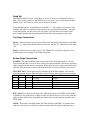
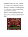
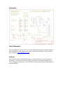
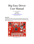
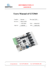
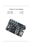
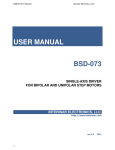
Big Easy Driver
User Manual
Doc version 1.1, for BED v1.1
5/18/2011
Brian Schmalz
Schmalz Haus LLC
www.schmalzhaus.com/BigEasyDriver
[email protected]
PRELIMINARY
Description
The Big Easy Driver (BED) is a major revision of the Easy Driver stepper driver board.
The BED takes power and control signals (STEP and DIRECTION) and produces the
signals necessary to step a 0A to 2Amp bi-polar stepper motor. The BED uses an Allegro
A4983 or A4988 driver chip.
Figure 1: Big Easy Driver v1.1
Hook Up
The BED has holes for both .100 headers as well as 3.5mm screw terminals. Either or
both can be used to connect to the BED however you want. You can put female or male
headers in the .100” holes or solder wires directly to the holes.
The minimum number of connections to the BED is 7 – four stepper wires, Power, Gnd
and Step. All others are optional. Note that there are two ground connections – one next
to the power input, and one next to the step input. Typically these will connect to the
power supply ground and the signal ground (from the microcontroller) respectively.
Top Edge Connections
Motor: Connect the four wires from the motor to the four motor connections on the BED.
The two “A” connections should connect to one coil, and the “B” connections to the other
coil.
Power: Connect the power input (+8 to +30V filtered DC) to the M+ connection, and
GND from the power supply to the GND connection.
Bottom Edge Connections
ENABLE: This input is pulled down on the board with a 20K Ohm resistor. You can
leave it disconnected, or you can drive it from your microcontroller. When low, the driver
chip is enabled and the motor is energized. When high, the driver chip is still enabled, but
all of the final motor drive circuits are disabled and so no current will flow to the motor.
MS1, MS2, MS3: These inputs are all tied high with 20K Ohm resistors. They set the
microstep setting. Use the following table to know how to control the microstep settings:
MS1 MS2
MS3
Microstep Resolution
Excitation Mode
L
L
L
Full Step
2 Phase
H
L
L
Half Step
1-2 Phase
L
H
L
Quarter Step
W1-2 Phase
H
H
L
Either Step
2W1-2 Phase
H
H
H
Sixteenth Step
4W1-2 Phase
RST: (Reset) This input is tied high with a 20K Ohm resistor on the BED. If this signal
is pulled low, the motor driver circuits are shut off, and the driver is reset. Only when this
input is high will the driver chip enable the motor driver circuits and pay attention to the
STEP input.
SLEEP: This input is tied high with a 20K Ohm resistor on the BED. To put the driver
chip into a lower power mode (motor driver circuits shut off, charge pump shut down,
etc.) pull this input low. When coming out of sleep, allow at least 1ms before sending
STEP pulses.
VCC: This is an output from the BED’s voltage regulator. The voltage regulator takes
the motor input voltage, and provides 5V (or 3.3V) for the logic inputs of the driver chip.
You can normally use about 85mA from this pin, although the higher the motor input
voltage is, the hotter the voltage regulator chip will get as you pull more current from this
pin. See the jumper configuration section below to switch this to 3.3V output.
GND: This is one of two ground connections on the BED. The other is on the topside
next to the M+ power input. Both grounds are internally tied together on the BED. This is
a good place to tie the ground of your microcontroller.
STEP: This input is tied high with a 20K Ohm resistor on the BED. Each rising edge of
this input will cause the stepper driver to advance one step in the direction specified by
the DIR input. The STEP input must be high for at least 1us, and low for at least 1us.
DIR: This input is tied high with a 20K Ohm resistor on the BED. When a STEP pulse is
received, the driver chip looks at this input to determine which direction to take the step.
When high, the motor will turn counterclockwise, and when low, the motor will turn
clockwise.
Figure 2: BED v1.1 Connection Placement Diagram
Jumper Configuration
There are two jumpers on the BED – APWR (Alternate Power) and 3/5V. They are
located in the upper left corner of the BED.
NOTE: On the v1.1 of the BED these two jumpers have their silk screen labels
reversed.
APWR (Alternate Power) – This jumper is normally closed (connected). If you cut the
trace between the two pads, the BED’s voltage regulator chip is disconnected from the
circuit, and you can then use the VCC connection on the bottom edge of the board as an
input, to power your BED with whatever logic level voltage you want to. (3.0V to 5.5V is
the accepted range.) You might choose this option if you wish to power your BED’s logic
level circuits with an external power source. This jumper is labeled SJ1 in the schematic.
3/5V – This jumper is normally open (dis-connected). You can switch the BED to use
3.3V for its logic level circuits by soldering this jumper closed. You would do this if you
wanted to interface your BED to a 3.3V microcontroller for example. This jumper is
labeled JS2 in the schematic.
Current Limit Set Potentiometer
The BED includes a very small pot to allow for the adjustment of the maximum current
level through the windings of the motor. On the board, this pot is labeled CUR ADJ.
Turning the pot clockwise decreases the maximum current, and turning it
counterclockwise increases the maximum current.
If your BED uses .22 ohm sense resistors: The range of the pot produces maximum motor
currents from around 0mA (fully clockwise) to 2.4A (fully counterclockwise).
If your BED uses .11 ohm sense resistors: The range of the pot produces maximum motor
currents from around 0mA (fully clockwise) to 5A (fully counterclockwise). Now, the
driver can’t supply 5A, so the full range of the pot won’t be used.
The TP1 testpoint can be used to measure the voltage on the CUR_REF net, which the
driver chip uses to determine the maximum current through the motor. See the driver chip
datasheet for the formula for converting this voltage into a max current setting.
Power LED
There is a yellow LED near the lower left corner of the BED labeled PWR. This LED
will light any time there is 5V or 3.3V being supplied to the driver chip. If this LED goes
off while there is still power being applied to the M+ and GND power inputs, then the
voltage regulator chip has either become too hot and shut down, or has detected a short
from VCC to GND and has shut off. If the LED turns on and off, then either the M+
power is turning on and off, or the voltage regulator chip is overheating and power
cycling to try and stay cool
Heat Dissipation
The Big Easy Driver can supply up to about 1.4A/phase of current at room temperature.
This is due to the four layer construction of the board and the way the board is laid out.
When driving high currents, the entire board will act as a heatsink, including the
connectors and anything the board is connected to. The driver chip has excellent over
temperature protection, so no damage can be done to the driver chip by running the board
too hot – it will simply cut out until the chip temperature returns to normal (less than
about 150C).
Adding a small heatsink (like Newark 43M6428) and/or using a small fan to cool the
drive chip can allow currents in excess of 2A/phase.
Motor Wiring
[coming soon]
Specifications
The specifications of the Big Easy Driver are the same as for the Allegro A4983 or
A4988 stepper driver chip (depending upon which is installed on the board). This
includes a maximum of 2A/phase, 16th, 8th, ¼, ½ and full step modes, 3.3V or 5V logic
inputs (jumper selectable).
Schematic
Parts Placement
This user manual is only an overview. For more information about the technical details of
how the BED drives the stepper motor, please see the official Allegro A4983 or A4988
driver datasheet. www.allegromicro.com
License
This document, and the entire BED design, are released under the Creative Commons
Attribution 3.0 US License. This means that you may use it for whatever purpose you
want, including commercial use, but you MUST give the original author (Brian Schmalz)
proper attribution.