1
Troubleshooting
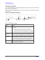
Using the System Board LEDs for Troubleshooting
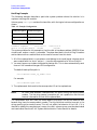
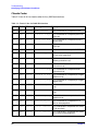
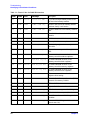
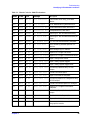
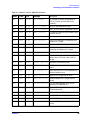
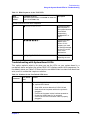
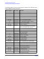
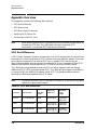
Table 3-3. Blink Sequences for the FANS LED
Blink
Sequence
Number
LED Blink Sequence
(black dot represents 0.1 second LED on; white dot
is 0.1 second LED is off)
Description
System Controller Error Blink Sequences
4
●❍❍❍❍❍❍❍❍❍
System controller
shut off power to
the system because
the ambient
temperature
exceeded 60˚C or
140˚F.
5
●●●●●●●●●❍
System controller
detects a fan
failure. If this
happens you need
to read the message
in the LCD on the
front of the
workstation.
6
●❍●❍●❍❍❍❍❍
System controller is
reporting an error.
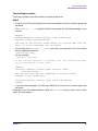
Troubleshooting with System Board LEDs
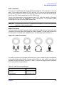
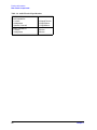
This section explains what to do when you see the LEDs on your system board in a
non-default state, and when the yellow FANS LED displays certain blink sequences. For
the default states, see Table 3-2. Note that the non-default state is a state that should not
exist, and it is a state that requires a solution.
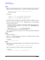
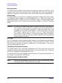
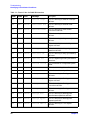
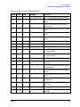
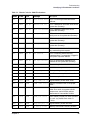
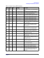
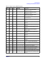
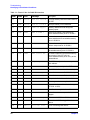
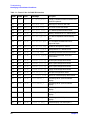
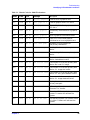
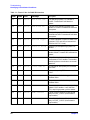
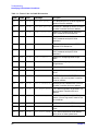
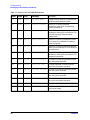
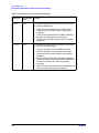
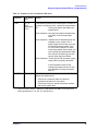
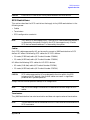
Table 3-4. Solutions for the Non-Default LED States
LED Name1
Non-Default
State
Solution
VRM1
OFF
If the following solutions do not bring this LED back
on, replace VRM1 board.
• Swap VRM cards to determine if VRM1 is bad
• Determine that the power cable to the system is
plugged in
• Check that the power button has been pressed on
• Re-seat the VRM1 board in its connector
• Check that the VRM1 connector cable is properly
plugged in
Chapter 3
73