1
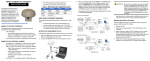
SPAN-SE Receiver QUICK START GUIDE This guide provides the basic information you need to set up and begin using your SPAN-SE receiver. BOX CONTENTS In addition to this Quick Start Guide, the following is provided in your SPAN-SE package: COM port using a straight-through serial cable. INSTALLING NOVATEL’S PC UTILITIES 1. Start the computer. 2. Insert the accompanying CD in the CD-ROM drive. 3. Select Install the OEMV GPS PC Utilities from the window that opens automatically. If the window does not open automatically when the CD is inserted, select Run from the Start menu and navigate to Setup.exe on the CD. 4. Follow the on-screen instructions to complete the software installation. • 1 SPAN-SE receiver SPAN HARDWARE SET-UP • 2 multi-connector cables • 1 mounting bracket with screws Complete the following steps to set up and power your SPANSE. • 1 6-foot USB 2.0 cable • 1 industrial SD memory card • 1 power cable • 1 multi I/O connector cover • 1 CD containing PC Utilities and product documentation • 1 patent notice and manual request postcard 1. Mount the IMU and antenna securely to a vehicle. Ensure that the devices cannot move and that the distance and relative direction between them is fixed. See also Step 2 in the Configure SPAN Manually section of this guide. 2. Connect the yellow cable’s 30-pin connector directly into the yellow port labelled I/O 2 on the SPAN-SE. The cable clicks when connected properly. ADDITIONAL EQUIPMENT REQUIRED Alternatively, you can connect the receiver to a computer with either a USB or Ethernet connection. See the SPAN-SE User Manual for information on USB or Ethernet connection options. 5. Connect the yellow cable’s IMU connector to an IMU with the IMU’s interface cable. 6. Insert the SD card into the slot behind the front panel door. Files stored on the SD card can be transferred to a host computer for data analysis or other types of postprocessing by using the CDU utility or by removing the SD card and inserting it into a host computer that has an SD card slot or an adapter attached. Refer to the SPAN-SE User Manual for detailed information on configuring the SPAN-SE communication ports. ESTABLISHING RECEIVER COMMUNICATION To open a serial port to communicate with the receiver, complete the following: 1. Open CDU from the Start menu folder specified during the installation process. The default location is Start | Programs | NovAtel PC Software | NovAtel CDU. 2. Select Open.... from the Device menu. 7. Apply power to the receiver. Do not press the power button; the receiver powers up automatically. If possible, add a back-up battery between the receiver and its voltage supply if installed in a vehicle. The backup battery acts as a buffer to prevent power dips tyhat can cause the receiver and IMU to lose lock and calibration settings. 3. Select the New... button in the Open dialog box. The Options | Configuration dialog opens. The following additional equipment is needed for a basic setup: • A Windows-based PC with an RS-232 DB9, USB or Ethernet port • A power supply that produces 12 – 28 volts DC • A quality dual frequency GNSS antenna such as the GPS-702, the GPS-702-GG, the ANT-A72GA-TW-N for airborne/high speed applications, or the GPS-702L antenna for L-Band corrections • A TNC to appropriate antenna connector RF cable • A SPAN-supported IMU such as NovAtel numbers: IMUH58, IMU-H62, IMU-H00, IMU-LN200, IMU-FSAS-EI, IMU- FSAS-EI-O, IMU-CPT, UIMU-LCI, HG1900 or HG1930 12V Voltage Supply + - 8. Connect additional serial communications equipment as needed. The following ports are available: 3. Connect the GPS antenna to the port labelled GPS1 on the receiver using an appropriate antenna cable. 4. Connect the yellow cable’s COM1 connector to a computer • 4 UART serial (RS-232/RS-422 configurable) • 1 USB • 1 Ethernet 4. Click the button to add a new configuration. To delete a configuration, select it from the list and click the button. To duplicate an existing configuration, click the button. You can select any name in the list to edit. Entering Commands and Receiving logs SPAN-SE has a comprehensive command/log interface that can be used with any command console. Using CDU 5. Select Serial from the Type list and select the computer port, that the SPAN-SE is connected to, from the Port list. CDU provides access to key information about your receiver and its position. The information is displayed in windows accessed from the View menu. For example, select Position Window from the View menu to display the position solution of the receiver. To show details of the GNSS and geostationary (SBAS) satellites being tracked, select a Tracking Status Window (GPS or GLONASS) from the View menu. Select Help from the main menu for more details on CDU, its windows and features. CONFIGURING GNSS Enabling SBAS Use the SBASCONTROL command to enable SBAS positioning. The following commands are used to enable the WAAS (North America) and EGNOS (Europe) systems respectively: 6. Select 115200 from the Baud Rate list. 7. Uncheck the Use hardware handshaking checkbox. 8. Click OK to save the new device settings. SBASCONTROL ENABLE WAAS SBASCONTROL ENABLE EGNOS 9. Select the new configuration from the Available device configs area of the Open dialog. When SBAS is enabled, the Position Type field in CDU’s Position window changes from Single to WAAS and SBAS satellites may appear in the Constellation window. 10. Click the Open button to open SPAN-SE communications. Enabling L-band L-band equipped receivers can achieve sub-meter accuracy. To use this positioning mode, enable L-band tracking to the OmniSTAR signal. A subscription to OmniSTAR is required to use the OmniSTAR VBS, XP or HP service (visit http:// www.omnistar.com with your receiver serial number ready). A progress box appears as CDU establishes communication with the receiver. Use the ASSIGNLBAND command to set OmniSTAR base station communication parameters. The parameters must include a relevant frequency and data rate. The frequency assignment can be made in Hz or KHz. For example: Hz: KHz: assignlband omnistar 1536782000 1200 assignlband omnistar 1536782 1200 A value entered in Hz is rounded to the nearest 500 Hz. To confirm that your receiver is tracking an L-band signal, log the L-band status information by entering: log lbandstat. To specify the correction source, use the PSRDIFFSOURCE command as shown in the example below: PSRDIFFSOURCE OMNISTAR Otherwise, leave the setting at the default AUTO. Refer to the OEMV Family Firmware Reference Manual for more on individual L-band, GLONASS or SBAS commands and logs. Enabling Real-Time Kinematic (RTK) Positioning Corrections can be transmitted from a base station to a rover station to improve position accuracy. The base station is the GNSS receiver that acts as the stationary reference. It has a known position and transmits correction messages to the rover station. The rover station is the GNSS receiver that does not know its exact position and can receive correction messages from a base station to calculate differential GNSS positions. You must create a data link between the base station and rover station (two NovAtel receivers) to transfer corrections. SBAS and L-band corrections can be accomplished with one receiver and are exceptions to the base/rover concept. A link capable of at least 9600 bits per second and less than 4.0 seconds of latency is recommended. When the base and rover stations are set up, you can configure them for RTCA, RTCM, RTCMV3, CMR+ or CMR corrections. Below is an RTCM example. Replace the latitude, longitude and height coordinates shown with those of your base: Base interfacemode com2 none rtcm off fix position 51.11358042 -114.04358013 1059.4105 log com2 rtcm3 ontime 10 log com2 rtcm22 ontime 10 1 log com2 rtcm1819 ontime 1 log com2 rtcm1 ontime 5 log com2 rtcm31 ontime 5,1 (optional GLONASS PSRDIFF) log com2 rtcm32 ontime 10,2 Rover gnsscardconfig rtcm none off RT-2 and RT-20-capable SPAN-SE receivers with AdVance RTK are real-time kinematic products developed by NovAtel. Optimal RTK performance requires both the base and rovers be NovAtel products. However, AdVance RTK operates with equipment from other manufacturers when using RTCM messaging. starts. IMU Type HG1900 IMU_HG1900_CA29 HG1930 IMU_HG1930_AA99 The inertial filter starts when the GPS solution is solved and the IMU is connected. RT-2 and RT-20 are supported by GPS+GLONASS and GPSonly OEMV-based models. Also, RT-20 with GPS+GLONASS provides faster convergence. 1. Refer to the GPGST log’s usage box in the OEMV Firmware Reference Manual for a definition of RMS and other statistics. 2. For more base/rover configurations, search for “rover base” on our Knowledge Database at: http://support.novatel.com/home A GPS antenna must be connected and actively tracking satellites for correct operation. complete. The SPAN-SE has a default logging profile with all raw data needed for post-processing. If you press the SD logging button, this profile automatically logs to a uniquely named file until the SD logging button is pressed again. To change the default logging profile, send the log requests that you want, the command: SETAUTOLOGGING ON and then SAVECONFIG. The newly-defined profile is automatically logged to the SD card on power up. For example: 2. Use the SETIMUTOANTOFFSET command to set the distance from the IMU to the GNSS antenna. The offset between the antenna phase centre and the IMU axes must remain constant and be accurate (m). The X (pitch), Y (roll) and Z (azimuth) directions are clearly marked on the IMU enclosure. The SETIMUTOANTOFFSET parameters are (where the standard deviation fields are optional): CONFIGURING THE SPAN IMU Configure SPAN with CDU Follow these steps to enable INS as part of the SPAN system using the NovAtel CDU software utility: 1. Select Tools | SPAN Alignment Wizard from the CDU menu to configure the lever arm and vehicle-to-body rotation information. The wizard guides you through the processes of completing a coarse or fast alignment, selecting the type of IMU and configuring the receiver to IMU port to accept IMU data. SETIMUTYPE Configure SPAN Manually Follow these steps to enable INS as part of the SPAN system using software commands: 1. Issue the SETIMUTYPE command to specify the IMU (Table 1). 2. Select Tools | SPAN Calibration Wizard to calibrate the lever arm or vehicle-to-body rotation information. The wizard guides you through the processes of calibrating the lever arm and/or vehicle to body rotation, as well as select the type of IMU and configure the receiver port connected to the IMU and to accept data. Table 1: Enable INS Commandsdd When you have made your selections in the SPAN wizard, click the OK button to enable the SPAN system. When the system is enabled, raw IMU data becomes available and the INS filter IMU Type SETIMUTYPE LN-200 IMU_LN200 iIMU-FSAS IMU_IMAR_FSAS IMU-CPT IMU_KVH_COTS UIMU-LCI IMU_LITEF_LCI HG1700 IMU_HG1700_AG11, or IMU_HG1700_AG17, or IMU_HG1700_AG58, or IMU_HG1700_AG62 x_offset y_offset z_offset [x_stdev] [y_stdev] [z_stdev] A typical RTK GPS solution is accurate to within a few centimeters. For the integrated INS/GPS system to have this level of accuracy, the offset must be measured to within a millimeter. Any bias between the two systems appears in the output position. For example, a 10 cm error in recording this offset will result in at least a 10 cm error in the output. If you cannot measure the IMU to GPS antenna offset precisely, perform the lever arm calibration routine to estimate offset. Refer to the SPAN-SE User Manual for details. LOGGING DATA You can collect data logs through any I/O port on the SPAN-SE receiver into any data capture software, including CDU. SPAN-SE also has a SD card for data collection. To send data to the SD card, open a files, then use FILE as the port designator in log requests. You must close the file when collection is LOGFILE OPEN TEST.GPS LOG FILE RANGECMPB ONTIME 1 LOGFILE CLOSE Save logs and commands with the SAVECONFIG command to ensure that the same logging configuration starts whenever the receiver is powered on. Remove the SD card from the receiver and plug it into a computer to download data from the card. The data logging button, located beside the SD card, stops and starts the data logging if you must change cards during operation. You can monitor the logs’ output to determine the system status. Multiple CDU windows show the status of various receiver subsystems. Light Emitting Diodes (LEDs) on the front of the SPAN-SE receiver also show the status of many subsystems. Log SPAN Data Raw GPS, IMU and navigation data (position, velocity and attitude) are available from the system as ASCII or binary logs. Data can be collected through CDU using the Logging Control window, or sent through the receiver COM port to user-supplied data collection software. For post-processing applications, collect the data shown in the Post-Processing section near the end of this guide. OPERATING THE SPAN SYSTEM Observe the status of the system in CDU’s INS window or in the status field of any of the INS solution logs (for example INSPOS, INSVEL, INSATT and INSPVA). INS data is available when the GPS solution has solved for time (i.e., FINESTEERING status). So, an antenna must be connected and tracking satellites for the system to function. Allow the system to be stationary for at least one minute after the GPS solution is computed for its initial system alignment. The following status stages may be observed: LED STATUS INDICATORS There are six LEDs on the front of the SPAN-SE receiver that represent the following status categories: • Power • SD card memory • Internal OEMV-3 card status (GPS 1) • Internal OEMV-2 card status (GPS 2) • INS filter • IMU communication antenna separation. LED Power OFF No power to the unit When using an IMU-CPT, a stationary alignment is only possible with a dual antenna SPAN-SE-D, or if the SETINITAZIMUTH or SETINITATTITUDE commands are issued. See the user manual for more information. The status may occasionally change to INS_BAD_GPS_AGREEMENT. This status indicates that the inertial solution has detected poor quality GPS positions from the receiver due to limited satellite visibility or high multipath conditions. The inertial filter may choose to disregard this information and wait for the GPS quality to improve. The solution is still valid during this status, but it is a warning that the GPS/ INS solution is more reliable than the GPS-only solution. Powered and the unit is off ORANGE N/A RED N/A Flashing: powered and the unit is on SD No card Card in Flashing: file open The following table details the states of each LED, which remain solid unless the table indicates a flashing condition. OEMV3 No board • The status changes from INS_INACTIVE to INS_ALIGNING when the coarse alignment starts • The status changes to INS_ALIGNMENT_COMPLETE when the coarse alignment is complete. Typically, the this state continues until the system senses motion. When the attitude solution converges to within specifications, the status changes to INS_SOLUTION_GOOD. GREEN Solution complete + fine steering No board Card in, low space Card in, full Flashing: file open Insufficient observations Receiver status error (bits: 0,1,2, 7) Receiver status error (bits: 0,1,2, 7) Solution good Aligning INS inactive Flashing: alignment complete Flashing: solution bad Good RAWIMU packets No RAWIMU (IMU type not set) Flashing: coarse steering INS IMU GPS only No IMU From the base station • RANGECMPB ontime 1 • RAWEPHEMB onchanged From the rover station(s) • RANGECMPB ontime 1 • RAWEPHEMB onchanged • RAWIMUSB onnew In addition, the following is required to log GLONASS: Insufficient observations Solution complete + fine steering • • Flashing: coarse steering OEMV2 The following logs are required for post-processing: IMU status error bits POST-PROCESSING Post-processing requires collection of simultaneous data from the base and rover stations. This includes accurate coordinates of the base station and accurate measurement of the IMU to • GLOEPHEMERISB onchanged • GLOCLOCKB onchanged The SPAN-SE system output is compatible with post-processing software from the Waypoint Products Group, NovAtel Inc. Visit their web page at http://www.novatel.com/products/waypointsoftware for more details. QUESTIONS OR COMMENTS If you have any questions or comments regarding your SPAN-SE system, please contact NovAtel Customer Service by: Email: [email protected] Web: www.novatel.com Phone: 1-800-NOVATEL (U.S. & Canada) 403-295-4900 (International) Fax: 403-295-4901 © Copyright 2011 NovAtel Inc. All rights reserved. Printed in Canada on recycled paper. Recyclable. Unpublished rights reserved under international copyright laws. GM-14915082 Rev 2 28/07/2011