1
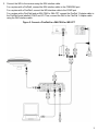
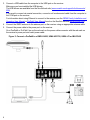
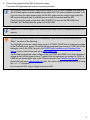
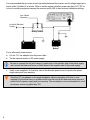
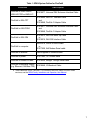
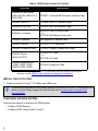
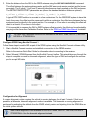
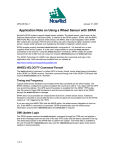
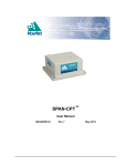
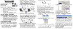
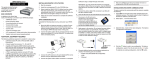
SPAN® on OEM6® QUICK START GUIDE GM-14915112 Rev 5 December 2013 This guide provides the basic information you need to set up and begin using your SPAN system. SPAN SYSTEM COMPONENTS A SPAN system requires the following primary components: • A SPAN capable OEM6 receiver (enclosure or receiver card) • An IMU (see the IMU Type column in Table 3, CONNECTIMU Commands) • A quality, dual frequency GNSS antenna such as the GPS-702-GG. See the NovAtel website (www.novatel.com/products/gnss-antennas/) for information on a variety of quality antennas available to meet your form factor and performance needs. • Cables to connect the components. See Table 1, SPAN System Cables for FlexPak6. • A power supply for the OEM6 receiver. For the receiver power requirements, refer to the OEM6 Family Installation and Operation User Manual or ProPak6 User Manual available on the NovAtel web site (www.novatel.com). • A power supply for the IMU. For the IMU power requirements, refer to the SPAN on OEM6 User Manual available on the NovAtel web site (www.novatel.com). If you want to use the same power supply for the receiver and the IMU, make sure the power supply meets the requirements of both the receiver and the IMU. 1 SET UP YOUR SPAN HARDWARE Complete the following steps to set up and power your SPAN system. This procedure focuses on a SPAN system with a FlexPak6 or ProPak6 receiver. For information about SPAN system installation with other OEM6 receivers, see the SPAN on OEM6 User Manual found on the NovAtel web site (www.novatel.com). 1. Mount the IMU and antenna securely to a vehicle. For the simplest operation, align the Y-axis of the IMU with the forward axis (direction of travel) of the vehicle. Ensure the Z-axis is pointing up. Ensure that the GNSS antenna and IMU cannot move relative to each other. The distance and relative direction between them must be fixed. Figure 1: Connect a FlexPak6 to a UIMU-LN200, UIMU-HG1700, UIMU-LCI or IMU-IGM 2 For additional connection diagrams, see the SPAN on OEM6 User Manual available on the NovAtel web site (www.novatel.com) 2. Connect the IMU to the receiver using the IMU interface cable. For a system with a ProPak6, connect the IMU interface cable to the COM3/IMU port. For a system with a FlexPak6, connect the IMU interface cable to the COM2 port. For a system with a FlexPak6 and an IMU-FSAS or IMU-CPT, connect the FlexPak Y Adapter cable to the FlexPak6 ports labelled COM 2 and I/O. Then, connect the IMU to the FlexPak Y Adapter cable using the IMU interface cable. Figure 2: Connect a FlexPak6 to a IMU-FSAS or IMU-CPT 3 3. Connect a USB cable from the computer to the USB port on the receiver. Make sure you have installed the USB drivers. The USB drivers are available from the NovAtel web site (www.novatel.com/support/info/documents/ 809). If you want to connect via a serial connection, connect a null modem serial cable from the computer to the COM port on the receiver. For information about using Ethernet to connect to the receiver, see the OEM6 Family Installation and Operation User Manual or ProPak6 User Manual found on the NovAtel web site (www.novatel.com). 4. Connect the GNSS antenna to the antenna port on the receiver using an appropriate antenna cable. 5. Connect the power cable to the power port on the receiver. On a FlexPak6 or ProPak6, line up the red mark on the power cable connector with the red mark on the receiver’s power port and insert power cable. Figure 3: Connect a ProPak6 to a UIMU-LN200, UIMU-HG1700, UIMU-LCI or IMU-FSAS 4 6. Connect the receiver and the IMU to the power supply. The power LED lights when the receiver is properly powered. The FlexPak6 requires a power supply that provides 6-36 V DC and is capable of at least 5 W. The ProPak6 requires a power supply that provides 9-36 V DC and is capable of at least 15 W. If you are using the same power supply for the IMU, make sure the voltage range meets the IMU requirements and there is sufficient power for both the receiver and the IMU. If you are using the stack up interface cable (01019013) to connect the IMU-IGM to the FlexPak6, the FlexPak6 provides power to the IMU-IGM. Operation of the SPAN system is not affected by the order in which you power up the IMU and receiver. If you are using custom cables for your installation, rather than the NovAtel cables listed in Table 1, be aware of the following. The FlexPak6 provides an output voltage on pin 4 of COM 2 (POUT) that is at the same voltage as the FlexPak6 power source. To ensure that any equipment you connect to COM 2 will not be damaged, refer to the COM 2 pinout in the OEM6 Family Installation and Operation User Manual found on the NovAtel web site at www.novatel.com. The ProPak6 provides the output voltage on pin 4 of COM1 and COM2 (Vout) that is the same voltage at the ProPak6 power source. To ensure that any equipment you connect to COM1 or COM2 will not be damaged, refer to the COM port pinout in the ProPak6 User Manual found on the NovAtel web site at www.novatel.com. Also, this output voltage can be turned on or off using the COMVOUT command. Do not use the POUT output voltage to power an IMU. 5 It is recommended that you place a back-up battery between the receiver and its voltage supply as a power buffer if installed in a vehicle. When a vehicle engine is started, power can dip to 9.6 V DC or cut-out to ancillary equipment causing the receiver and/or IMU to lose lock and calibration settings. from Vehicle Alternator to Vehicle Electrical System Battery Isolator Battery Vehicle Main Auxiliary Battery For an alternative power source: a. Cut the 12 V car adapter from the power cable. b. Tie the exposed wires to a DC power supply. c. 6 Be sure to connect the red and orange or green wires to the positive side of the power supply and connect the black and brown or white wires to the negative side of the power supply. Install a user supplied 6 A slow blow fuse at the alternate power source to protect the power supply wiring and your warranty. Since the 12V car adaptor on the supplied adaptor cable incorporates a 6A fuse, a user supplied 6A slow blow fuse in a suitable holder must be used at the alternate power source to protect both the power supply and your warranty. The car adapter is not recommended for use if your power source is greater than 12V. Table 1: SPAN System Cables for FlexPak6 Connectiona Cable required FlexPak6 to UIMU-LN200, UIMU-HG1700 or UIMU-LCI 01018977, Universal IMU Enclosure Interface Cable FlexPak6 to IMU-CPT 01018966, IMU-CPT Interface Cable and 01018948, FlexPak Y Adapter Cable FlexPak6 to iIMU-FSAS 01018977, Universal IMU Enclosure Interface Cable and 01018948, FlexPak Y Adapter Cable FlexPak6 to IMU-IGM 01019013, IMU-IGM Stack Up Cable or 01019016, IMU-IGM Interface Cable FlexPak6 to computer 60323078, USB A to mini B cable or 01017658, Null Modem Serial cable FlexPak6 to antenna User supplied RF antenna cable FlexPak6 to power 01017663, 12 V Power cable FlexPak6 to modem or radio 01018520, Straight Through Serial cable FlexPak6 to additional outputs (e.g. Ethernet, CAN Bus, PPS) 01018649, I/O Breakout Cable a. These cables are for the FlexPak6. For information about the cables for other OEM6 receivers, see the OEM6 Family Installation and Operation User Manual. 7 Table 2: SPAN System Cables for ProPak6 Connectiona Cable required ProPak6 to UIMU-LN200, UIMU-HG1700, UIMU-LCI or iIMU-FSAS 01018977, Universal IMU Enclosure Interface Cable ProPak6 to IMU-CPT 01018966, IMU-CPT Interface Cable ProPak6 to IMU-IGM 01019016, IMU-IGM Interface Cable ProPak6 to computer 60323078, USB A to mini B cable or 01017658, Null Modem Serial cable ProPak6 to antenna User supplied RF antenna cable ProPak6 to power 01017663, 12 V Power cable ProPak6 to modem or radio 01018520, Straight Through Serial cable ProPak6 I/O port (Event I/O, PPS) 01018649, I/O Cable or 01019148, I/O Cable ProPak6 Expansion port (COM7, COM8, COM9, COM10, CAN1, CAN2) 01019154, Expansion Cable a. These cables are for the ProPak6. For information about the cables for other OEM6 receivers, see the OEM6 Family Installation and Operation User Manual. INSTALL THE PC UTILITIES 1. Install the NovAtel Connect™ PC Utilities and USB drivers. To access and download the most current version of the NovAtel Connect PC Utilities and USB drivers, go to the Support page of the NovAtel web site at www.novatel.com/support/info/ documents/809. CONFIGURE THE SPAN SYSTEM There are two methods to configure the SPAN system: • Configure SPAN Manually • Configure SPAN Using NovAtel Connect™ 8 Configure SPAN Manually Follow these steps to enable INS as part of the SPAN system using software commands: 1. Establish a connection to the OEM6 receiver. Refer to the receiver Quick Start Guide for information about connecting to the receiver and entering commands. A GNSS antenna must be connected and tracking satellites for operation. 2. Issue the CONNECTIMU command to specify the type of IMU and the receiver port connected to the IMU (see Table 3, CONNECTIMU Commands). Table 3: CONNECTIMU Commands IMU Type CONNECTIMU command ADIS-16488 CONNECTIMU COMxa IMU_ADIS16488 HG1700 AG11 CONNECTIMU COMxa IMU_HG1700_AG11 HG1700 AG17 CONNECTIMU COMxa IMU_HG1700_AG17 HG1700 AG58 CONNECTIMU COMxa IMU_HG1700_AG58 HG1700 AG62 CONNECTIMU COMxa IMU_HG1700_AG62 HG1900 CA50 CONNECTIMU COMxa IMU_HG1900_CA50 HG1930 CA50 CONNECTIMU COMxa IMU_HG1930_CA50 iIMU-FSAS CONNECTIMU COMxb IMU_IMAR_FSAS IMU-CPT CONNECTIMU COMxb IMU_KVH_COTS IMU-IGM-A1 CONNECTIMU COMxa IMU_ADIS16488 IMU-IGM-S1 CONNECTIMU COMxa IMU_STIM300 LCI-1 CONNECTIMU COMxa IMU_LITEF_LCI1 LN-200 CONNECTIMU COMxa IMU_LN200 STIM300 CONNECTIMU COMxa IMU_STIM300 a. For systems with a ProPak6 receiver, you must use COM3/IMU for the IMU. For systems with a FlexPak6 receiver, COM2 is the recommended serial port for the IMU, however you can use COM1 or COM2 for these IMUs. If you are using the OEM615+MIC board stack, you must use COM1. b. For the iIMU-FSAS and IMU-CPT, you must use COM2 on the FlexPak6 or COM3/IMU on the ProPak6. Basic configuration of the SPAN system is now complete. The inertial filter starts once the GNSS solution is solved and the IMU is connected. 9 3. Enter the distance from the IMU to the GNSS antenna using the SETIMUTOANTOFFSET command. The offset between the antenna phase center and the IMU axes must remain constant and be known accurately. The X (pitch), Y (roll) and Z (azimuth) directions are clearly marked on the IMU enclosure. The SETIMUTOANTOFFSET parameters are (where the standard deviation fields are optional): x_offset y_offset z_offset [x_stdev] [y_stdev] [z_stdev] A typical RTK GNSS solution is accurate to a few centimetres. For the GNSS/INS system to have this level of accuracy, the offset must be measured to within a centimetre. Any offset error between the two systems shows up directly in the output position. For example, a 10 cm error in recording this offset will result in at least a 10 cm error in the output. If it is impossible to measure the IMU to GNSS antenna offset precisely, the offset can be estimated by carrying out the Lever Arm Calibration Routine. Refer to the SPAN on OEM6 User Manual for details. The Lever Arm Calibration Routine is not available for the ADIS-16488, IMU-CPT, IMU-IGM, HG1930 or STIM300 IMUs. Configure SPAN Using NovAtel Connect™ Follow these steps to enable INS as part of the SPAN system using the NovAtel Connect software utility: 1. Start a NovAtel Connect session and establish a connection to the OEM6 receiver. Refer to the receiver Quick Start Guide for information about connecting to the receiver. 2. Select Wizards | SPAN Alignment from the NovAtel Connect toolbar. This wizard takes you through the steps to complete a coarse or kinematic alignment, select the type of IMU and configure the receiver port to accept IMU data. Configuration for Alignment A coarse alignment routine requires the vehicle to remain stationary for at least 1 minute. If that is not possible, an alternate, kinematic alignment routine is available. The kinematic or moving alignment is performed by estimating the attitude from the GNSS velocity vector and injecting it into the SPAN filter as the initial system attitude. 10 Static coarse alignment is not available for the ADIS-16488, IMU-CPT, IMU-IGM, HG1930 or STIM300 IMUs. Use the kinematic alignment instead. LOG SPAN DATA Raw GNSS, IMU and navigation data (position, velocity, attitude) are available from the system as ASCII or binary logs. Data can be collected through NovAtel Connect using the Logging Control Window, or sent out the receiver COM port to user-supplied data collection software. For post-processing applications, collect the data shown in the Post-Process Data section of this guide. For real-time applications, the GNSS/INS solution is available through the logs listed in the SPAN on OEM6 Firmware Reference Manual including INSPOS, INSVEL, INSATT and INSPVA. These logs can be collected at rates up to the IMU data rate; however, there are some rate restrictions. Refer to the Data Collection section in the SPAN Operation chapter of the SPAN on OEM6 User Manual. OPERATE THE SPAN SYSTEM The system is ready to go once it is powered and the GNSS and INS are configured using the previously shown commands. Observe the status of the system in the NovAtel Connect INS Window or in the status field of any of the INS solution logs (for example INSPOS, INSVEL, INSATT and INSPVA). INS data is available after the receiver’s time status has reached FINESTEERING. Therefore, an antenna must be connected for the system to function. If performing a static alignment, allow the system to be stationary for at least 1 minute after the GNSS solution is computed for its initial system alignment. If performing a kinematic alignment, move the vehicle forward at a speed faster than 5 m/s. The following status stages may be observed: • The status changes from INS_INACTIVE through DETERMINING_ORIENTATION, WAITING_INITIALPOS and INS_ALIGNING as the initial alignment routine starts. • The status changes to INS_ALIGNMENT_COMPLETE when the alignment is complete. After some motion (stops, starts and turns), the attitude solution converges to within specifications and the status changes to INS_SOLUTION_GOOD. • The status may occasionally change to INS_SOLUTION_FREE. This status indicates that the inertial solution has detected poor quality GNSS positions from the receiver due to limited satellite visibility or high multipath conditions. The inertial filter may choose to disregard this information and wait for the GNSS quality to improve. The solution is still valid during these times, it is simply a notification that the GNSS/INS solution is more reliable than the GNSS-only solution. 11 POST-PROCESS DATA Post-processing requires collection of simultaneous data from the base and rover stations. This includes accurate coordinates of the base station and accurate measurement of the IMU to antenna separation. Collect the following data for post-processing: • From the base station • RANGECMPB ontime 1 • RAWEPHEMB onchanged • GLOEPHEMERISB onchanged (if using GLONASS) • From the rover station(s) • RANGECMPB ontime 1 • RAWEPHEMB onchanged • GLOEPHEMERISB onchanged (if using GLONASS) • RAWIMUSXB onnew • IMUTOANTOFFSETSB onchanged • VEHICLEBODYROTATIONB onchanged • HEADINGB onnew (if using ALIGN dual antenna solution) SPAN system output is compatible with Inertial Explorer® post-processing software from the Waypoint® Products Group, NovAtel Inc. Visit our website at www.novatel.com/products/software/ for details. QUESTIONS OR COMMENTS If you have any questions or comments regarding your SPAN system, contact NovAtel Customer Service by: Email: [email protected] Web: www.novatel.com Phone: 1-800-NOVATEL (U.S. & Canada) 1-800-668-2835 1-403-295-4500 (International) Fax: 1-403-295-4501 NovAtel, SPAN, OEM6, Inertial Explorer, and Waypoint are registered trademarks of NovAtel Inc. FlexPak6, ProPak6, NovAtel Connect and IMU-IGM are trademarks of NovAtel Inc. Windows is a registered trademark of Microsoft Corporation. © Copyright 2013 NovAtel Inc. All rights reserved. Printed in Canada on recycled paper. Recyclable. Unpublished rights reserved under international copyright laws. 12