1
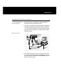
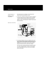
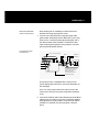
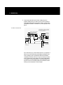
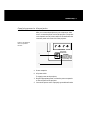
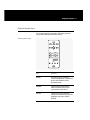
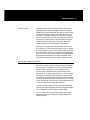
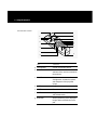
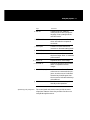
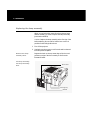
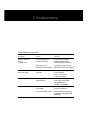
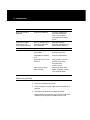
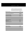
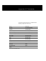
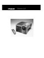
Polaview 220
FCC Statement
Warning: This equipment generates, uses and can
radiate radio frequency energy and, if not installed and
used in accordance with the instruction manual, may
cause interference to radio communications. It has been
tested and found to comply with limits for a Class “A”
computing device pursuant to Subpart B of Part 15 of
the FCC Rules, which are designed to provide reasonable
protection against such interference when operated in a
commercial environment. Operation of this equipment in
a residential area is likely to cause interference in which
case the user, at his own expense, will be required to
take whatever measures may be necessary to correct the
interference. Shielded cables must be used with this unit to
ensure compliance with the Class A FCC limits.
Canadian Notice
This digital apparatus does not exceed the Class A limits
for radio noise emissions from digital apparatus set out
in the Radio Interference Regulations of the Canadian
Department of Communications.
Le présent appareil numérique n’émet pas de bruits
radioélectriques dépassant les limites applicables aux
appareils numériques de la classe A prescrites dans le
Règlement sur le brouillage radioélectrique edicté par le
ministère des Communications du Canada.
European Notice
Warning: This is a Class A product. In a domestic
environment this product may cause radio interference
in which case the user may be required to take adequate
measures. The “CE” mark certifies that this product
satisfies the requirements of the EU (European Union)
regarding safety, public health, environment and
consumer protection. (“CE” is the abbreviation of
Conformité Européenne.) This product is in conformity
with the following directives: 73/23/EEC, low voltage
directive; 89/33/EEC, EMC directive; 93/68/EEC,
“CE” marking directive.
© Copyright 1996 Polaroid Corporation. All rights reserved.
Specifications are subject to change without notice.
Table of contents
1 Introduction
What’s in the box?
2
Computer/video compatibility
3
Quick start
4
2 Detailed setup
Your Polaview Model 220 Projector
7
Getting started
9
Connector panel
10
Computer and VCR connections
11
Supplying power to the projector
15
3 Using the projector
Turning on the projector and lamp
17
Control-panel keys
20
Using the remote control
23
Using the remote control
24
Image optimization
25
ii Table of contents
4 Maintenance
Storage, cleaning and care
29
Replacing the lamp
30
5 Troubleshooting
Troubleshooting guide
33
Where to get help
34
Polaroid Offices and Service Centers
35
One Year Warranty
37
Appendix A: Parts
39
Appendix B: Standards
41
1 Introduction
Thank you for purchasing the Polaview Model 220 Digital
Light Processing (DLP) Projector, one of an innovative line
of advanced presentation products from Polaroid.
Your Polaview Model 220 Projector is a valuable presentation tool that can project images from a computer or video
source onto a large screen or wall, in a range of 16.7 million
true, saturated colors with unprecedented image quality.
The Polaview Model 220 Projector is designed for easy
setup and operation for virtually any group setting. Please
read the following instructions carefully. Should you have
questions about the setup or operation of your projector, or
about accessories and how to order them, please contact
Polaroid Electronic Imaging Technical Support (see
Polaroid Offices and Service Centers in Chapter 5 for
details).
2 Introduction
What’s in the box?
The Polaview Model 220 Projector is shipped with the following accessories. See Appendix A: Parts for a complete
list of accessories and corresponding part numbers.
Items included
with the projector
a
b
4
3
2
1
MAC
ADAP II
TER
TO VG
A
ADO6
C
ADO8
TO MA
c
d
e
f
g
h
i
j
k
a Polaview Model 220 Projector
b Remote control
c Mac multiscan redrive adapter
d VGA/Mac II adapter
Introduction 3
e Mac monitor redrive
f VGA/Mac II reversible cable
g 1/8 in. phono-to-RCA adapter cable
h 1/8 in. phono jack cable
i
RCA composite video cable
j
Power cord (USA)
k Power cord (EC/UK)
Also included but
not shown
• Computer infrared receiver kit
• Mouse driver for PC and adapter kit for PC and Mac
• User’s guide
Other accessories
(not included)
Additional accessories are available for use with the
projector:
• Carrying case with wheels
• ATA-300-style carrying case with wheels
• Replacement lamp assembly
• S-video cable
See Appendix A: Parts for part numbers and information on
ordering accessories.
Computer/video compatibility
The Polaview Model 220 Projector is compatible with a variety of computer and video sources. Refer to Appendix B:
Standards for a list of computer and video sources that are
compatible with the projector.
4 Introduction
Quick start
The following steps outline the basic setup procedure for
connecting the projector to your computer. Detailed information about connections for various computer sources is
described in Chapter 3, Detailed setup.
1 Aiming the projector lens at the projection screen, place the
projector on a solid, flat surface, at a right angle (perpendicular) to the projection screen and parallel to the floor. Place
the projector the proper distance from your viewing screen.
2 Connect your computer or video source to the projector
(refer to the appropriate section for your computer, in Chapter 3, Detailed setup, for detailed instructions).
Connector panel
SOURCE 1
L
R
SOURCE 2
L
R
VIDEO INPUTS
SOURCE 3
SOURCE 4
STEREO
STEREO
MAC / PC
PC / MAC
OUTPUTS
STEREO
REDRIVE
L
R
RS 232
COMPUTER INPUTS
Input: 120/230V~
60/50Hz,5.0/2.5A
CAUTION !
For continued protection against the risk of fire,
replace only with the same type and rating of fuse.
Double pole / Neutral fusing
Type and Rating: T Slow-blow, 6.3A, 250V-
3 You can simultaneously view your desktop computer monitor and project computer images with the projector by connecting your monitor to the REDRIVE port on the rear panel
OUTPUTS section. (Refer to the applicable setup procedure
in Chapter 3, Detailed setup to connect your monitor.)
Introduction 5
4 To supply power to the projector, connect the power cable
to the power port on the rear panel of the projector. Then
connect the power cord to an appropriate power outlet.
Turn on the power switch located on the rear panel of the
projector, beside the power port. After approximately 30
seconds after the power is on, a solid-colored image is projected onto your screen.
Note: You may detect a high-pitched sound as the colorwheel and fans are reaching operating speed. Also, as you
turn on the projector, you may detect a slight, crackling,
electrostatic sound as the bulb illuminates. It may take up to
10 seconds for the bulb to reach full brightness.
A keystone correction of 17 degrees is built into the projector to compensate for image distortion. You may want to
adjust the rear feet of the projector to position the image on
the screen.
5 Turn on your computer or video source. Select the desired
source for display by pressing the appropriate SOURCES
button on the projector control panel or remote control.
Your computer or video image then appears on the projection screen. The selected SOURCES button is backlit green;
all other SOURCES buttons are backlit red.
Note: For information about the operation of your external
computer or video sources, refer to the appropriate instruction manual for the equipment in question.
6 Focus the projected image with the FOCUS control either on
the control panel or remote control. Adjust the image size
by using the ZOOM control on the control panel or remote
control. Use the projector SETUP and IMAGE menus to
adjust the settings to fine-tune your projected image. (For
more detailed instructions for image adjustments, see
Chapter 4, Using the projector.
6 Introduction
Note: Whenever you connect the projector to a computer or
video source for the first time, the projector defaults to the
factory settings. Due to operational differences between
computers and video sources, it may be necessary to make
minor adjustments to the settings. See Image optimization
in Chapter 4, Using the projector for more information. The
projector stores any modified settings, even when the
power is turned off.
Note: Audio and video sources must be connected to the
same computer or video source to be selected simultaneously.
7 To activate audio, connect the audio cables (from your computer, compact disc player, stereo, etc.) to the STEREO port
that corresponds to the source connected in step 2. The
audio source plays through speakers built into the projector.
You may also connect amplified speakers or headphones to
the OUTPUT connector labeled STEREO or L and R. This
automatically deactivates the projector speakers.
Note: If you connect a mono or single-jack stereo source to
the left (L) audio port (with nothing plugged into the right
(R) audio port), the sound emanates from both speakers.
8 Begin your presentation.
Note: For setup procedures for the Computer IR (infrared)
Receiver, refer to the separate instruction manual included
in your Computer IR Receiver Kit.
2 Detailed setup
Your Polaview Model 220 Projector
This chapter describes setup procedures for connecting
your Polaview Model 220 Projector to a compatible
computer. It also provides instructions on how to set up
the projector for use with various video sources.
Before you begin, examine the components of the
projector.
The Polaroid Polaview
Model 220 Projector
and remote control
a
b
c
d
e
D LP
D LP
4
3
2
1
a Control panel
b Infrared sensor
c Lamp assembly door latch
d Projection lens assembly
e Handle
f
Remote control
f
8 Detailed setup
The Polaroid Polaview
Model 220 Projector –
rear view
g
SOURCE 1
L
R
SOURCE 2
L
R
SOURCE 3
STEREO
MAC / PC
VIDEO INPUTS
SOURCE 4
STEREO
PC / MAC
OUTPUTS
STEREO L
REDRIVE
COMPUTER INPUTS
R
RS 232
h
i
j
g Connector panel
h Green LED power indicator
i
AC power switch
j
Power-cord receptacle
Detailed setup 9
Getting started
Positioning the
projector
Place the projector on a solid, flat surface at a right angle
(perpendicular) to the projection screen and parallel to the
floor. If you use a media cart, make sure the wheels are
locked to prevent it from moving.
Opening the casing of your projector could damage the
components inside and will void your warranty. Dropping
or mishandling the projector can damage the optical path.
Ceiling mount
The projector is capable of displaying inverted images
for ceiling mount configurations, but special mounting
equipment is required for mounting the unit. A qualified
technician, responsible for meeting safety standards and
obtaining any and all required safety inspections, should
install this equipment.
Transporting the
projector
The projector has a handle located on one of the side panels.
Always use the handle to transport the projector.
For air travel, the standard carrying case with wheels is
adequate for transporting your projector as carry-on luggage
only. If you check your projector through as regular luggage,
ship it in the optional ATA-style case only.
Projector cooling
and airflow
Let the projector cool as required by allowing for proper
airflow through its ventilation system. Air intake and exhaust
grills are on the bottom of the projector.
Caution: Never operate the projector if these grills are
clogged or obstructed, or if the electric fans are not running.
10 Detailed setup
Connector panel
All connections between the projector and your computer or
video source are made on the rear connector panel.
The connector panel
SOURCE 1
L
R
SOURCE 2
L
R
VIDEO INPUTS
SOURCE 3
SOURCE 4
STEREO
STEREO
MAC / PC
PC / MAC
OUTPUTS
STEREO
REDRIVE
L
R
RS 232
COMPUTER INPUTS
Input: 120/230V~
60/50Hz,5.0/2.5A
CAUTION !
For continued protection against the risk of fire,
replace only with the same type and rating of fuse.
Double pole / Neutral fusing
Type and Rating: T Slow-blow, 6.3A, 250V-
Note: Whenever you connect the projector to a computer or
video source for the first time, the projector defaults to the
factory settings. Due to operational differences between
computers and video sources, it may be necessary to make
minor adjustments to the settings. See Image optimization
in Chapter 4, Using the projector for more information. The
projector stores any modified settings and defaults to them
when you turn the power off and on again.
Detailed setup 11
Computer and VCR connections
Connecting IBM PCs
and compatibles
Place the projector on a tabletop or other level surface
with the lens facing the projection screen.
1 Connect your computer to the projector with the VGA/Mac II
reversible cable (part number CA18). Plug the end labeled
“To VGA” into the monitor port of your computer. Plug the
other end into the “PC/MAC” port of the projector (see the
illustration below).
IBM connections
SOURCE 1
L
R
SOURCE 2
L
R
SOURCE 4
STEREO
STEREO
MAC / PC
PC / MAC
OUTPUTS
STEREO
REDRIVE
L
R
RS 232
COMPUTER INPUTS
ADO6
VIDEO INPUTS
SOURCE 3
SOURCE 3
SOURCE 4
Redrive
TO MAC
C
TO VGA
TO MA
IBM PC
monitor
cable
VGA / MAC II
cable
TO VGA
Mac II adapter
to VGA / MAC II cable
2 IBM PC
CPUs
2 If you want to be able to view your computer monitor and
project images with the projector simultaneously, connect
your VGA monitor cable directly to the REDRIVE port on the
projector connector panel.
12 Detailed setup
Connecting Mac II,
Quadra, LC, and
Powerbook and
compatibles
Place the projector on a tabletop or other level surface
with the lens facing the projection screen.
1 Connect your computer to the projector with the VGA/Mac II
reversible cable (part number CA18). Plug the end labeled
“To Mac” into the computer monitor port. Plug the end
labeled “To VGA” into the projector “MAC/PC” port (see the
illustration below).
Macintosh connections
SOURCE 1
L
R
SOURCE 2
L
R
VIDEO INPUTS
SOURCE 3
STEREO
SOURCE 4
STEREO
MAC / PC
PC / MAC
SOURCE 3
SOURCE 4
Redrive
OUTPUTS
STEREO
REDRIVE
L
R
RS 232
Mac redrive adapter
to Macintosh
monitor cable
COMPUTER INPUTS
VGA/
MAC II
ADO6
MAC
ADA II
PTER
TO VG
A
TO VG
A
C
TO MA
C
TO MA
Mac II adapter
to VGA/MAC II
cable
2 Macintosh
CPUs
2 If you want to be able to view your computer monitor and
project images with the projector simultaneously, connect
the Mac monitor redrive adapter (part number AD06) to the
REDRIVE port on the projector connector panel and then
plug your Macintosh monitor cable into the adapter.
Note: If you are connecting a Macintosh multiscan monitor
you need to substitute the Mac multiscan redrive adapter
(part number AD08) for the Mac monitor redrive adapter
(part number AD06).
Detailed setup 13
NTSC/PAL/SECAM
video connections
Place the projector on a tabletop or other level surface
with the lens facing the projection screen.
1 Connect one of the yellow RCA composite video cable
(part number CA19) plugs into the VIDEO OUT jack of your
video source. Connect the yellow plug at the other end of
the cable to either of the SOURCE 1 or SOURCE 2 videoinput composite jacks (yellow) on the projector connector
panel (see the illustration below).
Composite video
connections
VCR or laser disk player
AUDIO VIDEO S-VIDEO
L R
White
SOURCE 1
Red
SOURCE 2
Yellow
SOURCE 1
L
R
SOURCE 2
L
Yellow
Red
VIDEO INPUTS
R
SOURCE 3
SOURCE 4
STEREO
STEREO
MAC / PC
PC / MAC
OUTPUTS
STEREO
REDRIVE
L
R
RS 232
COMPUTER INPUTS
White
Use SOURCES 1 and 2 to
connect more than one
audio/video device
(one cable per device)
Audio/Video cable
The projector is also compatible with S-video sources
(for the appropriate connections, refer to the illustration on
the next page).
Note: You must connect audio and video sources to the
same source channel if you plan to select them simultaneously.
2 Connect the red RCA audio-video cable plug to the AUDIO R
(right) jack of your audio source. Then connect the red plug
at the projector end of the cable to a red audio jack (either
SOURCE 1 or SOURCE 2 R) on the projector connector
panel.
14 Detailed setup
3 Connect the white RCA audio-video cable plug to the
AUDIO L (left) jack of your audio source. Then connect the
white plug at the projector end of the cable to a white audio
jack (either SOURCE 1 or SOURCE 2 L) on the projector rear
panel.
S-video connections
Use SOURCES 1 and 2 to connect
more than one audio/video device
(one cable per device)
VCR or laser disk player
SOURCE 1
SOURCE 2
AUDIO VIDEO S-VIDEO
L R
SOURCE 1
L
R
SOURCE 2
L
Red
R
SOURCE 3
STEREO
PC / MAC
VIDEO INPUTS
White
SOURCE 4
STEREO
MAC / PC
OUTPUTS
STEREO
REDRIVE
L
R
RS 232
COMPUTER INPUTS
S-VHS cable
Audio/Video cable
Yellow
(not
connected)
Yellow
(not
connected)
Red
White
Note: Whenever you connect the projector to a computer or
video source for the first time, the projector defaults to the
factory settings. Due to operational differences between
computers and video sources, it may be necessary to make
minor adjustments to the settings. See Image optimization
in Chapter 4, Using the projector for more information.The
projector stores any modified settings and defaults to them
when you turn the power off and on again.
Detailed setup 15
Supplying power to the projector
After you connect the projector to your computer or video
source, connect the power cord to the projector. The powercord receptacle and AC power switch are located below the
connector panel on the rear side of the projector.
Power receptacle
and AC power
switch
VIDEO INPUTS
a
Input: 120/230V~
60/50Hz,5.0/2.5A
CAUTION !
For continued protection
replace only with the sam
Double pole / Neutral fusi
Type and Rating: T Slow-
b
a Power receptacle
b AC power switch
To supply power to the projector:
1 Plug the appropriate power cord into the power receptacle
on the rear panel of the projector.
2 Connect the power cord to a properly-grounded wall outlet.
3 Using the projector
Turning on the projector
Turn on the power switch located on the rear panel of
the projector, beside the power port. After approximately
30 seconds after the power is on, a solid blue image is
projected onto your screen. Whenever the power is on,
the green LED power indicator on the rear panel of the
projector glows a steady green.
Note: You can detect a high-pitched sound as the colorwheel and fans are reaching operating speed. Also, when
you turn on the projector, you can detect a slight, crackling,
electrostatic sound as the bulb illuminates. This is normal.
It may take up to 10 seconds for the bulb to reach full
brightness.
Caution: Never operate the projector if the air intake or
exhaust grills are clogged or obstructed, or if the electric
fans are not running.
Turn on your computer or video source. Select the desired
source for display by pressing the appropriate SOURCES
button on the projector control panel or remote control.
Your computer or video image then appears on the projection screen. The selected SOURCES button is backlit green;
all other SOURCES buttons are backlit red.
18 Using the projector
Focusing and zooming
the image
Focus the projected image with the FOCUS control either
on the control panel or remote control. Adjust the image
size by using the ZOOM control on the control panel or
remote control.
Keystone correction
A keystone correction of 17 degrees is built into the
projector to compensate for image distortion. You may
want to adjust the rear feet of the projector to position
the image on the screen.
Image size
The projector 20–30mm (1.5:1) motorized zoom/focus lens
provides a high-quality display that ranges from 36 to 240
inches (diagonal). The size of the projected image changes
as you move the projector closer to the screen or adjust the
zoom lens. The following table indicates the minimum and
maximum distance from the projector to the screen for
most standard size projection screens.
Projected image
(diagonal)
Distance from projection screen
Minimum
Maximum
36 in.
42 in.
62.4 in.
60 in.
70.8 in.
104.4 in.
120 in.
141.6 in.
208.8 in.
180 in.
211.2 in.
313.2 in.
240 in.
282 in.
417.6 in.
If you wish to compute your own measurements, use the
following formula:
MIN 20mm:
Diagonal/.85 = Distance from screen
MAX 30mm:
Diagonal/.574 = Distance from screen
Using the projector 19
Control-panel keys
The control-panel keys are used to adjust the projected
image and to display and hide the menus.
Control-panel keys
IMAGE
SOUND
SET UP
ENTER
ENTER
–
MUTE
VOLUME
+
CURTAIN
–
ZOOM
+
POSITION
–
FOCUS
+
–
PICTURE
+
SOURCES
1
2
3
4
LAMP
Key
Function
IMAGE
Provides access to menus for
control of brightness, contrast, tint,
phase, and sharpness of the
projected image.
SOUND
Controls the volume, balance,
treble, and bass of the source
connected to the projector.
SET UP
Controls front, rear, table-top,
ceiling-mount modes of projection;
language; and factory-setting
defaults.
20 Using the projector
Key
Function
ENTER L & R
Nonfunctional keys, reserved for
future product development.
Cursor pad
Controls on-screen menus and
increases or decreases setting
levels.
MUTE
Turns the audio on or off.
CURTAIN
Toggles between a displayed image
and a blank blue screen.
POSITION
Allows positioning of the displayed
image, when used with the cursor
pad.
VOLUME +/-
Decreases or increases the volume.
ZOOM +/-
Zooms in and out. Press + to make
the picture larger. Press - to make
the picture smaller.
FOCUS +/-
Adjusts the focus of the image.
PICTURE +/-
Adjusts the brightness and contrast
ratios of computer and video
images.
SOURCES 1, 2, 3, 4
Permits selection of one of four
active sources connected to the
projector. An active source is
indicated when the key is backlit
green. Inactive sources are indicated
when keys are backlit red.
LAMP
Disables or enables the lamp for
Standby mode operations.
Using the projector 21
Standby mode
Use the Standby mode to prolong the life of the projector
lamp. When you select the Standby mode by pressing the
LAMP key, the green LED power indicator on the rear panel
of the projector begins to blink and continues to do so for
3 minutes, to allow the projector to cool down. The projector must complete this 3-minute cool-down period before it
can resume normal operation. The green LED resumes its
normal steady glow at the end of 3 minutes. Press the
LAMP key again to resume operation of the projector.
Warning: The projector lamp should always be turned on
for a minimum of 3 minutes and allowed to cool for at least
3 minutes before you turn it back on again. Failure to follow
these precautions can lead to premature lamp degradation
and, on rare occurrences, lamp rupture. Do not operate the
lamp past the rated lamp life. Excessive operation of the
lamp past its rated life can cause them to fracture or burst.
Using the remote control
The remote control contains all the key functions available
on the projector control panel as well as several additional
features. For the projector to receive signals from the
remote control, point the remote control directly at the
infrared sensor on top of the projector. You can also deflect
the remote-control signal off the projection screen. When
used with the computer IR (infrared) receiver kit, the remotecontrol cursor pad controls the movement of your computer
cursor. The remote control also has a low-powered laser for
use as a pointing device during presentations.
Note: For setup procedures for the computer IR (infrared)
receiver, refer to the separate instruction manual included in
your computer IR receiver kit (part number SB06).
Caution: Take care not to point the remote-control laserlight beam toward your audience. The light beam could
cause eye injury.
22 Using the projector
The remote control
a
h
SET
b
c
SOU
IM
UP
i
ND
ENT
AGE
ER
ENT
LA
ER
d
–
MUT
VOL
E
IN
P
+
ZOO
–
IO
OSIT
N
k
l
m
n
+
UME
–
TA
CUR
e
j
SER
M
FOC
US
+
PICT
–
+
URE
SOU
RCE
44
S
22
11
o
33
LAM
P
f
p
g
Key
Function
a Laser pointer
Serves as a pointing device.
b SOUND
Controls the volume, balance, treble,
and bass of the source connected to
the projector.
c IMAGE
Provides access to menus for control
of brightness, contrast, tint, phase,
and sharpness of the projected
image.
d LASER
Toggles the laser pointer on and off.
e MUTE
Turns the audio on or off.
f CURTAIN
Toggles between a displayed image
and a blank screen.
g POSITION
Allows positioning of the displayed
image, when used with the cursor
pad.
Using the projector 23
Key
Function
h SET UP
Controls front, rear, table-top,
ceiling-mount modes of projection;
language; factory-setting defaults;
and video mode.
i ENTER L & R
Performs previous or next functions,
when used with the computer IR
receiver kit.
j Cursor pad
Controls on-screen menus and
increases or decreases setting levels.
k VOLUME +/-
Decreases or increases the volume.
l ZOOM +/-
Zooms in and out. Press + to make
the picture larger. Press - to make the
picture smaller.
m FOCUS +/-
Adjusts the focus of the image.
n PICTURE +/-
Adjusts the brightness and contrast
ratios of computer and video
images.
o SOURCES 1, 2, 3, 4
Permits selection of one of four
active sources connected to the projector. An active source is indicated
when the key is backlit green. Inactive sources are indicated when keys
are backlit red.
p LAMP
Disables or enables the lamp for
Standby mode operations.
Operating the projector
The control panel and remote control provide access to
all projector features. Press a key to select a function or to
navigate through the menus.
24 Using the projector
Menu selections
IMAGE menu
SOUND menu
Select the IMAGE menu to control the brightness, contrast,
tint, phase, and sharpness of the projected picture.
Option
What it does
BRIGHTNESS
Increases or decreases the intensity
level of the projected image.
CONTRAST
Adjusts the contrast of the projected
image.
TINT
Adjusts the red or green color balance
of the projected image.
SHARPNESS
Eliminates horizontal disturbance
from the computer video signal.
PHASE
Eliminates vertical bars from
computer images. This adjustment is
not necessary for most computers.
Adjust only when vertical bars are
present.
PICTURE
Adjusts the brightness and contrast
ratio of computer and video images.
PIXEL DROP
Optimizes DOS text. This adjustment
is only available in text mode when
you manually select text “videomode”
from the SETUP menu.
Select the SOUND menu to adjust the VOLUME, BALANCE,
TREBLE, and BASS of the source connected to the projector.
Using the projector 25
SETUP menu
Select the SETUP menu to make adjustments to the
following settings:
Option
What it does
PROJECTION (FRONT/REAR)
Selects the projected
display orientation for front
or rear projection mode.
LOCATION (TABLE/CEILING)
Inverts the projected image
orientation for use with a
ceiling mount.
LANGUAGE
Converts the on-screen
menus from English to
French, German, Spanish.
FACTORY SETTINGS
Resets all adjustments to
the factory-default settings.
VIDEO MODE
Selects either PAL or
SECAM operation.
If you are not actively using a menu, after approximately
10 seconds, it automatically disappears from the screen,
to be replaced by your projected image.
26 Using the projector
Image optimization
Making adjustments
to settings
Use the projector SETUP and IMAGE menus to adjust the
settings to fine-tune your projected image.
Your projector factory-default settings are designed
to configure it with your computer and video sources
automatically to provide a high-quality projected image.
Because of operational differences between the projector
and computer and video sources, you may want to make
minor setting adjustments to optimize your displayed
image. After connecting your projector to the desired
source and turning on your equipment, view a test image
on your computer monitor that typifies what you want to
display for presentation purposes.
Eliminating phase bars
Examine the projected image for evenly spaced
“vertical noise” or “phase” bars. Use the PHASE
option to eliminate them:
1 From the projector control panel or remote control,
press the IMAGE menu key.
2 Using the cursor pad, scroll through the menu selections
and highlight PHASE on the on-screen menu display.
3 Use the left arrow (<) or right arrow (>) key on the cursor
pad to eliminate the phase bars. Try both arrow keys and
select the one that reduces the number of “phase bars”
on the screen (by spacing the bars farther apart from one
another). Continue pressing the same arrow key until you
remove all phase bars from the screen. (You may still notice
horizontal noise or jittering on the screen; see the following
for correction.)
Using the projector 27
Eliminating
horizontal noise
Examine the projected image for horizontal noise bars or
jittering around text or icons. Use the SHARPNESS option to
eliminate them:
1 From the projector control panel or remote control, press
the IMAGE menu key.
2 Using the cursor pad, scroll through the menu selections
and highlight SHARPNESS on the on-screen menu display.
3 Use the left (<) or right arrow (>) key on the cursor pad to
eliminate the horizontal noise bars. Adjust the SHARPNESS
setting until the horizontal noise bars or jittering disappears.
Correcting loss of
picture detail
Examine the projected image to evaluate the proper level
of brightness and image depth. Use the BRIGHTNESS and
CONTRAST options to correct the loss of picture detail:
1 From the projector control panel or remote control, press
the IMAGE menu key.
2 Using the cursor pad, scroll through the menu selections
and highlight, alternately, the BRIGHTNESS and CONTRAST
options on the on-screen menu display.
3 Use the left (<) or right (>) arrow key on the cursor pad to
adjust brightness and contrast. The correct combination of
brightness and contrast provides a bright image with correct gray tones on computer images and does not obscure
details in video images.
28 Using the projector
True-to-life color
rendition
Examine the projected image for true-to-life color rendition.
Use the TINT option to make the adjustments:
1 From the projector control panel or remote control, press
the IMAGE menu key.
2 Using the cursor pad, scroll through the menu selections
and highlight TINT on the on-screen menu display.
3 Use the left (<) and right (>) arrow keys on the cursor pad to
adjust the color balance of the projected image.
Restoring factory
settings
If desired, you can restore the original factory settings by
selecting the SETUP menu key, using cursor pad to select
the RESET option, and depressing the right arrow key. Any
changes from the default setting are stored in memory for
that source.
Note: If for any reason the projector should not respond to
the control panel or remote control commands, you can
reset it by performing the following steps:
1 Turn off the unit and allow it to cool for at least 3 minutes.
2 Press the SET UP key on the projector control panel and
turn on the projector as you continue pressing the SET UP
key. Continue to press the SET UP key until the LEDs of the
SOURCE 1–4 keys on the control panel light up red and
green.
3 Release the SET UP key.
4 Reconfigure the projection settings for rear projectors, ceiling mount, as required.
4 Maintenance
Storage, cleaning and care
Store the Polaview Model 220 Projector either in its original
shipping container or carrying case to guard it against dust
and lint. Use a non-abrasive, lint-free cloth and non-abrasive
cleaning solution, such as an eyeglass or camera-lens cleaning solution, on the lens to keep it clean. Spray the cleaning
solution directly on the cleaning cloth, never on the lens.
Warning: Always disconnect your projector from its electri-
cal supply before performing any maintenance on it.
Extreme temperatures
Do not expose the projector to temperatures less than
-13°F (-25°C) or greater than 140°F (60°C). For example,
avoid storing it in parked automobiles for an extended
period of time. Do not operate the projector in temperatures
less than 32°F (0°C) or greater than 95°F (35°C).
30 Maintenance
Replacing the lamp assembly
When you notice that the output from the projector lamp
starts to weaken, you need to replace the lamp assembly
(part number 623374).
Caution: Replace the lamp assembly at the first sign of the
bulb weakening. Do not wait for bulb to burn out as it is
possible for the failing bulb to burst.
1 Turn off the projector.
2 Unplug the projector power cord from the wall socket and
from the power receptacle.
Remove the lampassembly door
Depress the latch on the top center edge of the door and
pull the top edge of the door toward you. Refer to the
illustration below.
The lamp assembly
and lamp-assembly
door
Door latch
D LP
Locking key
Handle
Maintenance 31
Remove the
lamp assembly
Unlock the lamp assembly by rotating the locking key on
the right side of the lamp assembly counter-clockwise onehalf revolution. Grasp the wire handle and gently pull the
lamp assembly straight out of the unit.
Replace the
lamp assembly
Align the lamp-assembly slide rails with the slide-rail
channels inside the projector and gently slide the lamp
assembly into the projector. When the lamp assembly is
properly in seated in the projector, rotate the locking key
clockwise one-half revolution.
Note: Take care not to touch the lamp in the new assembly.
The smallest oil deposit from your finger can significantly
shorten the life of the lamp.
Replace the
lamp-assembly door
Align the tabs on the bottom of the door with the slots
in the door opening. Gently push the top of the door into
place until the latch snaps into position. Turn the projector
on to verify that the lamp functions properly.
Note: The removal of the lamp-assembly door activates a
safety switch that disconnects electrical power from the
lamp assembly. Improper installation of the lamp assembly
can prevent the safety switch from being reactivated.
Warning: When you replace the lamp assembly, always
disconnect the projector from its power source. Do not rely
solely on the safety switch to disconnect power from the
assembly.
Warning: The lamp assembly reaches extremely high tem-
peratures during normal operation. If you need to replace
the lamp assembly after operating the projector, let the unit
cool in Standby mode for at least 30 minutes before
attempting to remove the lamp assembly. When you use
the Standby mode, power is still being fed to the projector.
Do not try to replace the lamp assembly or any electronic
components unless you unplug the unit from the power
source.
5 Troubleshooting
Troubleshooting guide
Symptom
Cause
Solution
Projector does not
turn on;
no lights or fan
Lamp-assembly door
not closed correctly
Refer to lamp assembly
replacement procedure
and verify proper installation
No power to unit
Try another electrical outlet
Blown input power fuse(s)
Call Polaroid Technical Support
Vertical bars appear
across the image
Nonstandard computer
clock rate
Press the IMAGE key and
scroll to PHASE;
press < > cursor keys
to remove the bars
Image is upside down
Incorrect projection
mode selected
Press the SETUP key
and scroll to LOCATION;
select DESKTOP or
CEILING, as applicable
Image rolls vertically
Improper cables/
loose cables
Check for correct cables
and snug connection
Incorrect computer setup
Check computer video mode
of operation (see Appendix B:
Standards)
34 Troubleshooting
Symptom
Cause
Solution
Solid-color screen is
displayed
Projector is initializing
If screen is displayed for
more than 15 seconds,
press a source button
associated with an active
source
Lamp does not light,
green LED on rear
control panel is flashing
Unit is in Standby mode
and bulb-restrike timer
has not elapsed
Wait approximately
3 minutes, if bulb does not
light press the LAMP key
Image is not in color
Incorrect computer video
Reboot your computer
No projected image
Improper cables/
loose cables
Check for proper cables
and snug connection
CURTAIN (blue display)
is on
Press the CURTAIN key
Active light source is not
selected
Verify proper connection
and press source key
associated with
an active source
Video source has not
been activated
Common problem with
laptop computers, contact
your computer dealer
Where to get help
If at any time you need help:
1 Check the Troubleshooting guide.
2 Call your dealer’s technical support line and explain your
problem.
3 Call Polaroid Corporation (see pages 35 and 36).
Please have the serial number of your unit (located on the
underside of the projector) available when you call.
Troubleshooting 35
Polaroid Offices and Service Centers
Australia
Polaroid Australia Pty. Ltd.
13–15 Lyonpark Road
P.O. Box 163
North Ryde, N.S.W. 2113
Tel.: (02) 9 950 7000
Fax: (02) 887 2209
Belgique/België
Polaroid (Belgium) N.V.–S.A.
Rue Colonel Bourg 111
Kolonel Bourgstraat 111
1140 Bruxelles–1140 Brussel
Tel.: 32 2 702 86 20
Fax: 32 2 726 92 99
Toll free: 32 78 155 905
Brasil
Polaroid do Brasil Ltda.
Av. Paulista, 1776–11º andar
Cerqueira Cesar
São Paulo–Capital
01310-921
Tel.: 55.11.285.6411
Fax: 55.11.283.2625
288.6521
287.5393
Canada
Polaroid Canada Inc.
350 Carlingview Drive
Etobicke, Ontario M9W 5G6
Toll free: 1-800-268-6970
Danmark
Polaroid a.s.
Blokken 75
3460 Birkerød
Tlf.: 42 81 75 00
Fax: 42 81 70 26
Deutschland
Polaroid GMBH
Sprendlinger Landstrasse 109
63069 Offenbach
Tel.: 069 8404 1
Fax: 069 8404 204
España
Polaroid (España), S.A
Calle Orense, 16
2a planta
28020 Madrid
Tno: 34-1-597.02.52
Fax: 34-1-597.27.82
France
Polaroid (France) S.A.
B.P. 7
78996 Elancourt Cédex
Tel.: (1) 30 68 38 38
Fax: (1) 30 68 38 39
Hong Kong
Polaroid (Far East) Ltd.
32/F Windsor House
311 Gloucester Road
Causeway Bay
Tel.: (852) 2894 0333
Fax: (852) 2895 1382
Italia
Polaroid (Italia) S.p.A.
Via Piave 11
21051 Arcisate (Varese)
Tel.: 0332-470031
Fax: 0332-478249
Japan
Nippon Polaroid
Kabushiki Kaisha
Mori Building No. 30
Toranomon 3-2-2
Minato-ku
Tokyo 105
Tel.: 81-3-3438-8811
Fax: 81-3-3433-3537
México
Polaroid de México S.A. de C.V.
Paseo de la Reforma 195
Piso 17
C.P. 06500 México, D.F.
Tel.: 703-1111
Fax: 566-0505
Del interior al 91 (800) 70-727
Ventas 91 (800) 70-747
Nederland
Polaroid Nederland B.V.
Zonnebaan 45
3606 CH Maarssen
PO Box 1219
3600 BE Maarssen
Tel.: 31-30-2-410-420
Fax: 31-30-2-411-969
Reparaties:
Polaroid (Europe) B.V.
Hoge Bothofstraat 45
7511 ZA Enschede
Tel.: 31-53-4-865-400
36 Troubleshooting
New Zealand
Polaroid New Zealand Ltd.
Camera Services
24-26 Anzac Avenue
Auckland
Tel.: (09) 377 3773
Norge
Polaroid (Norge) A/S
Industriveien 8B, 1473 Skårer
Postboks 80, 1471 Skårer
Tlf: 67 90 47 10
Fax: 67 90 51 73
Österreich
Polaroid Ges.m.b.H.
Eitnergasse 5A
1231 Wien
Tel.: 869 86 27
Fax: 869 81 00
Portugal
Polaroid (España) S.A.
Sucursal em Portugal
Edificio Monumental
Avenida Praia da Vitória, 71-A 4º B
1050 Lisboa
Tel.: (01) 316.10. 52
Puerto Rico
Polaroid Caribbean Corporation
Centro de Seguros
Ave. Ponce de León 701
Miramar, Santurce 00907
Tel.: (809) 725-6240
Fax: (809) 725-5462
Schweiz/Suisse/Svizzera
Polaroid AG
Hardturmstrasse 133
8037 Zürich
Tel.: (01) 277.72.72
Suomi
Polaroid Oy
Sinikalliontie 10
02630 Espoo
Puh: 90-502 35 33
Fax: 90-502 35 50
Sverige
Polaroid AB
Ekholmsvägen 34
Box 204
127 24 Skärholmen
Tel.: 08-710 08 50
Fax: 08-740 73 68
U.K.
Polaroid (U.K.) Ltd. &
Polaroid Export Operations
Wheathampstead House
Codicote Road
Wheathampstead
Hertfordshire AL4 8SF
U.K.
Tel: (44) 1582 632000
Freefone: 0800 010119
U.S.A.
Polaroid Corporation
Technical Assistance
Tel.: Toll free 1-800-432-5355
Call for the nearest Polaroid
location
Troubleshooting 37
One Year Warranty
Polaroid Corporation warrants your Polaview Projector
equipment against defects in manufacture for a period of
one year from the date of purchase. To verify the warranty
period, you should keep the sales slip or other proof of the
purchase date.
Should this product, or any component or accessory
included with it, become defective at any time during the
warranty period, Polaroid Corporation will, at its discretion,
either replace or repair this item, without charge, provided
the product is returned to a designated servicing location
(prepaid and insured). To ship the unit, pack the carrying
case in the original carton or equivalent, with plenty of
padding.
This Limited Warranty does not apply to product damage
resulting from accident, incorrect installation, unauthorized
modification, misuse or abuse.
U.S.A. and Canada
Before you return your equipment for repair, please call
Polaroid Electronic Imaging Technical Support from within
the U.S.A. at 1-800-432-5355, Monday through Friday, 8 a.m.
to 8 p.m., Eastern Time. In Canada, call 1-800-268-6970.
We can help you determine what is at fault, and advise you
on how and where to get service in the quickest and most
convenient way.
THIS WARRANTY EXCLUDES ALL INCIDENTAL AND
CONSEQUENTIAL DAMAGES. ALL EXPRESSED OR
IMPLIED LIABILITY FOR THIS EQUIPMENT INCLUDING
BUT NOT LIMITED TO THE IMPLIED WARRANTY OF
MERCHANTABILITY AND FITNESS FOR A PARTICULAR
PURPOSE ARE LIMITED IN DURATION TO THE ONE-YEAR
WARRANTY PERIOD.
38 Maintenance
SOME STATES DO NOT ALLOW THE EXCLUSION OR
LIMITATION OF INCIDENTAL OR CONSEQUENTIAL
DAMAGES OR THE DURATION OF IMPLIED WARRANTIES
SO THE ABOVE LIMITATIONS MAY NOT APPLY TO YOU.
THIS WARRANTY GIVES YOU SPECIFIC LEGAL RIGHTS,
AND YOU MAY ALSO HAVE OTHER RIGHTS WHICH MAY
VARY FROM STATE TO STATE.
Outside the U.S.A.
and Canada
THIS WARRANTY EXCLUDES ALL INCIDENTAL AND
CONSEQUENTIAL DAMAGES AND DOES NOT AFFECT
YOUR STATUTORY RIGHTS.
Note: No user-serviceable parts inside, with the exception
of the lamp assembly which can be replaced as described in
this manual. Attempts to modify mechanical or electronic
parts inside will void your warranty, and may be hazardous.
Appendix A: Parts
Listed below are all standard accessories available from
Polaroid for use with the Polaview Model 220 Projector.
These standard items are shipped with each model. The
appropriate Polaroid part number is listed with each item.
Replacement product
Part No.
Instruction manual
OG45
US power cord or EC and UK power cord
PC01 or
PC02 and 03
Mac monitor redrive adapter
AD06
Mac multiscan redrive adapter
AD08
VGA/Mac adapter
AD07
Phono -to-RCA adapter cable
CA26
1/8 in. phono cable
CA25
VGA/Mac II reversible cable
CA18
Remote control
RC41
Computer infrared receiver kit
SB06
RCA composite video cable
CA19
Internal NTSC/PAL/SECAM video board
UP40
Optional accessory
Part no.
Carrying case with wheels
623375
ATA-300-style carrying case with wheels
623376
Replacement lamp assembly
612273
S-video cable
CA14
40 Appendix A
You can order accessories and replacement parts through
your local dealer or by contacting Polaroid (see pages 35
and 36).
Appendix B: Standards
The Polaview 220 Model Projector is compatible with the
following computer and video sources:
Source
Resolution
Mac 12 in.
512 x 384 (60, 60.15hz)
VGA Text
720 x 400 (70hz)
VGA Hi Res Graphics
640 x 480 (60, 72, 75hz)
VGA Lo Res Graphics
640 x 400 (70)
Mac II, Quadra, LC, Powerbook
640 x 480 (60, 66.67hz)
NEC PC 98011
640 x 400 (56.4 hz)
VESA
640 x 480 (72hz)
VDMT
640 x 480 (75hz)
SVGA
800 x 600 (56-75hz)
Mac 16 in. monitor
832 x 624 (75hz)
NTSC 3.58
(30hz)
PAL BGHI/SECAM
(25hz)
S-video
1
indicates optional cable/adapter required.
“Polaroid” and “Polaview” are trademarks of Polaroid Corporation, Cambridge, MA, U.S.A. Inc. “Digital Light Processing”
and “DLP” are trademarks of Texas Instruments. “Apple” and “Macintosh” are registered trademarks of Apple Computer, Inc. “IBM” is a registered trademark of International Business Machines, Inc. Other trademarks may be the property of
their respective owners. U.S. patent numbers 4,763,993, 4,976,536, 5,153,621, and 5,150,238 apply to the Polaview
Model 220. Other U.S. and foreign patents are pending.
PXW8556A 10/96 Printed in U.S.A.