1
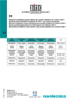
Logic T
Manuale di installazione quadro elettrico per cancelli a 1 motore 400 V~
Electric board installation handbook for gate with 1 motor 400 V~
Manuel d'installation armoire électrique pour portails à 1 moteur 400 V~
Steuerung Montagehandbuch für Gittertüren mit 1 Motor 400 V~
Manual de instalaciòn cuadro electrico para cancelas 1 motor 400 V~
DATI
TECNICI
TECHNICAL
DONNEES TECHNISCHE
DATEN
TECHNIQUES
DATA
Alimentazione Power supply Alimentation
Uscita
motore
Motor
output
Sortie
moteur
Alimentation
Safety
Alimentazione
accessories accessoires
accessori
sicurezza power supply de securité
(nominale)
(nominal)
(nominale)
(max.)
(peak)
(picco)
IP1609 13-03-2001
Temperatura Temperature
DATOS
TECNICOS
Stromzufuhr Alimentaciòn
Motor
Ausgange
Salida
motor
Sicherheits- Alimentaciòn
accessorios
Zubehöre
Stromzufuhr de seguridad
(nominale)
(Nominal)
(pico)
(Spitze)
Logic T
400 V~ / 50 Hz
400 V~
6 A max.
24 V
24 V
/ 0.3A
/ 0.5A
Temperature
Temperatur
Temperatura
-15 °C / +50 °C
Schutzgrad
Gràdo IP
IP54
Grado IP
Degree IP
Degré IP
Dimensioni
Dimensions
Dimensions
Abmessungen Dimensiones
DITEC S.p.A.
Via Mons. Banfi, 3
21042 Caronno P.lla (VA) Italy
Tel.+39 02 963911 - Fax +39 02 9650314
www.ditec.it
ISO 9001 - Cert. n° 0957/0
225x320x120
F5
F4
O
P
E
N
Logic T
FA FC
ON
POWER
SA
RP TC
12
UWV
L3L2 L1
M
3~
F3 F2 F1
L3L2 L1
400 V~
Autotest
Sicurezza d'inversione / Reversal safety contact
Stop-Autoritenuta / Stop - Control hold down
Apertura parziale / Partial opening
Chiusura autom. / Automatic closure
Apertura / Opening
Chiusura / Closing
Passo-passo / Step by step
Sicurezza in apertura / Safety while opening
Sicurezza in chiusura / Safety while closing
Lampeggiante/ Flashing light
Alimentazione accessori Accessories power supply +
1412 11 0 0 1 1 2 3 4 5 6 7 8 9 20 41
F1,2,3= F8 A GL linea / line / ligne / Linea / linea
F4=
F630 mA trasformatore / transformer /
transformateur / Transformator / transformador
F5=
F3.15A accessori / accessories/ accessoires / Zubehör / accessorios
Fig. 1
PARALLELO AUTOMAZIONI - PARALLEL CONNECTION - AUTOMATISMES EN PARALLELE PARALLELSCHALTUNG VON ZWEIR STEUERUNGEN - AUTOMATIZACIONES EN PARALELO
NOT J1
J2=CH1
J1
J2
COM NO
B
Logic T
Logic T
RADIO
Bix LR2
41
20
9
8
7
6
5
4
3
2
1
0
41
20
A 9
8
7
6
5
4
3
2
1
0
NO
RADIO
Fig. 2
DITEC S.P.A - IP1609 - Logic T
2
1.
ELECTRICAL CONNECTION
1.1 Controls
Description
1
2 N.O. AUTOMATIC CLOSURE
The automatic closure function is enabled by a permanent contact.
1
3 N.O. OPEN
It starts the opening operation.
1
4 N.O. CLOSE
It starts the closing operation.
1
5 N.O. STEP BY STEP
It starts the closing or opening operation in sequence:
open-stop-close-open. Warning: if the automatic closure
is enabled, the stop is not permanent but lasts for the time
set by means of TC.
1
6 N.C. OPENING SAFETY CONTACT It stops the gate and carries out a disengagement
monoeuvre (for 1 s) during opening operation. (Refer to TC
setting chapter 1.3.1).
1
7 N.C. CLOSING SAFETY CONTACT It stops the gate and carries out a disengagement
monoeuvre (for 1 s) during closing operation. (Refer to TC
setting chapter 1.3.1).
1
8 N.C. REVERSAL SAFETY
CONTACT
Reverses movement (re-opens) during closing. When door
is not moving, inhibits all operation.
(Refer to TC setting chapter 1.3.1).
1
9 N.C. STOP / CONTROL HOLD
DOWN
It stops any movement. If contact remains open, service
man function is enabled. Under these conditions, triggering of any of the safety devices causes gate to immediately stop moving. Step-by-step and automatic closing
controls are disabled.
1
20 N.O. PARTIAL OPENING
It causes a timer-controlled opening that is set via trimmer RP.
0
11 N.C. CLOSING LIMIT SWITCH
Stops gate during closing.
0
12 N.C. OPENING LIMIT SWITCH
Stops gate during opening.
OPEN
STEP BY STEP / OPEN
WARNING:
This is the seat for the coupling of the radio receiver.
The remote control function is select by means of DIP1
(OFF = 1-5; ON = 1-3).
Link up all N.C. contacts (if not used) by means of jumpers.
The terminal bearing the same number are equivalent.
The given operating and performance features can only be guaranteed with the use of
DITEC accessories and safety devices.
1.2 Output and accessories
Value
Output
Description
1
0
+
-
0
14
24V
/ 50 W
Flashing light (LAMPH). It is activated upon opening or closing. For
pre-flashing see DIP2.
1
11
24V
/3W
Gate open lamp.
41
24V
/ 0.3 A (nominal) Accessories power supply. Output for power external accessories
0.5 A (peak) including the gate-open signal lamp.
Autotest. Control for activation of autotest (For self-controlled safety
devices: HIP SICUR, SICUR).
5
DITEC S.P.A - IP1609 - Logic T
ENGLISH
Function
Control
1.3
Setting and adjustments
1.3.1 Trimmer
TC Automatic closure time. From 0 to 120 s with TC from min. to max.. Count down initiates or starts up again:
- according to the time set by TC: - at the end of opening;
- upon an open command being given, when the gate is stationary in the
open position.
- for half of the time set by TC: - after triggering a safety device (1-6 / 1-7 /1-8)
- at the end of partial opening.
With 1-2 or 1-9 open, automatic closing is disabled. Closing 1-2 re-enables automatic closing. If disabled
from 1-9, automatic closing is once again enabled, by contacts 1-9 being reclosed, only after an open
command is given.
RP Partial opening time. From 0 to 30 s, with RP set from min to max.
1.3.2 Dip-switch
OFF
1-5
ENGLISH
DIP1- Radio control selector
DIP2- Pre-flashing (fixed at 3 s)
1.3.3 Selection
Led POWER ALARM
Led SA
Led FA
Led FC
1.3.4 Parallel connection
ON
1-3
Disabled during opening, and Enabled both during opening and
enabled only during automatic closing.
closing with TC set to more than 3 s.
ON
OFF
/
This indicates that at least one of the 16, 1-7, 1-8 or 1-9 contacts is open.
This indicates that the 0-12 contact is open
This indicates that the 0-11 contact is open
/
Power ON
/
Two motors A and B in parallel may be controlled by wiring up as shown in
the figure 2, bearing in mind that terminals 0 and 5 of the two boards are not
to be connected. For automatic closing by both motors, proceed as follows:
- make a jumper between 1 and 2 in both A and B;
- set TC to the same value on both A and B.
2. STARTING UP
WARNING: the operations regarding point 2.2 are without safety devices.
the trimmer can only be adjusted with gate not moving.
2.1 Set TC at maximum and RP to the minimum. Short circuit the safety devices and the stop device.
2.2 Power and check the gate function correctly with a sequence open, close or step-by-step command. Check
for proper tripping of the limit switches. N.B.: the maximum operting time is of 90 s.
2.3 Remove the jumpers and connect the safety devices (1-6, 1-7 and 1-8) and the stop (1-9) Check their function.
2.4 If desired, connect 1-2 and adjust the automatic closure with TC. Warning: the automatic closure time after
the operation of one of the safety devices is half the set time. If desired, adjust partial opening time by
means of RP.
2.5 Connect any accessories and check their function.
2.6 Re-close the container by means of the 4 screws, taking care to properly position the cover (lower side =
Devoid of gasket).
All right reserved
All data and specifications have been drawn up and checked with the greatest care. The manufacturer cannot however take any responsibility
for eventual errors, ommisions or incomplete data due to technical or illustrative purposes
DITEC S.P.A - IP1609 - Logic T
6
ITALIANO
AVVERTENZE GENERALI PER LA SICUREZZA
Il presente manuale di installazione è rivolto esclusivamente a personale professionalmente competente.
L’installazione, i collegamenti elettrici e le regolazioni devono essere effettuati nell’osservanza della Buona Tecnica e in ottemperanza alle
norme vigenti.
Leggere attentamente le istruzioni prima di iniziare l’installazione del prodotto. Una errata installazione può essere fonte di pericolo.
I materiali dell’imballaggio (plastica, polistirolo, ecc.) non vanno dispersi nell’ambiente e non devono essere lasciati alla portata dei
bambini in quanto potenziali fonti di pericolo.
Prima di iniziare l’installazione verificare l’integrità del prodotto. Non installare il prodotto in ambiente e atmosfera esplosivi: presenza di
gas o fumi infiammabili costituiscono un grave pericolo per la sicurezza.
I dispositivi di sicurezza (fotocellule, coste sensibili, stop di emergenza, ecc.) devono essere installati tenendo in considerazione: le
normative e le direttive in vigore, i criteri della Buona Tecnica, l’ambiente di installazione, la logica di funzionamento del sistema e le forze
sviluppate dalla porta o cancello motorizzati.
Prima di collegare l’alimentazione elettrica accertarsi che i dati di targa siano rispondenti a quelli della rete di distribuzione elettrica.
Prevedere sulla rete di alimentazione un interruttore/sezionatore onnipolare con distanza d’apertura dei contatti uguale o superiore a 3 mm.
Verificare che a monte dell’impianto elettrico vi sia un interruttore differenziale e una protezione di sovracorrente adeguati.
Collegare la porta o cancello motorizzati a un’efficace impianto di messa a terra eseguito come previsto dalle vigenti norme di sicurezza.
Il costruttore della motorizzazione declina ogni responsabilità qualora vengano installati componenti incompatibili ai fini della sicurezza e
del buon funzionamento.
Per l’eventuale riparazione o sostituzione dei prodotti dovranno essere utilizzati esclusivamente ricambi originali.
La manipolazione delle parti elettroniche deve essere effettuata munendosi di bracciali conduttivi antistatici collegati a terra.
GENERAL SAFETY PRECAUTIONS
This installation manual is intended for professionaly competent personnel only.
The installation, the electrical connections and the settings must be completed in conformity with good workmanship and with the laws in
force.
Read the instructions carefully before beginning to install the product. Incorrect installation may be a source of danger.
Packaging materials (plastics, polystyrene, etc) must not be allowed to litter the environment and must be kept out of the reach of children
for whom they may be a source of danger.
Before beginning the installation check that the product is in perfect condition.
Do not install the product in explosive areas and atmospheres: the presence of flammable gas or fumes represents a serious threat to
safety. The safety devices (photoelectric cells, mechanical obstruction sensor, emergency stop, etc) must be installed taking into account:
the provisions and the directives in force, good workmanship criteria, the installation area, the funtional logic of the system and the forces
developed by the motorised door or gate. Before connecting to the mains check that the rating is correct for the destination power
requirements. A multipolar isolation switch with minimum contact gaps of 3 mm must be included in the mains supply.
Check that upstream of the electrical installation there is an adequate differential switch and a suitable circuit breaker.
Ensure that the motorised door or gate has an earth terminal in accordance with the safety regulations in force.
The manufacturer of the motorising device declines all responsability in cases where components which are incompatible with the safe
and correct operation of the product only original spare parts must be used.
For repairs or replacements of products only original spare parts must be used.
It is recommended that antistatic conductive earthed arm bands be worn when manipulating electronic parts.
ENGLISH
AVVERTENZE DI INSTALLAZIONE
Fissare il quadro elettrico in modo permanente. Forare il contenitore del quadro elettrico nel lato inferiore per il passaggio dei cavi.
Se accessibili, bloccare i cavi medianti opportuni pressacavi (non di nostra fornitura). Mantenere separati di almeno 8 mm i conduttori di
linea e motore dai conduttori comandi nei punti di connessione alle morsettiere (per esempio con fascette). Collegare insieme i conduttori
di protezione (colore giallo/verde) della linea e dei motori mediante il morsetto in dotazione. Richiudere il contenitore con le 4 viti posizionando correttamente il coperchio (lato inferiore = privo di guarnizione)
CONSIGNES GENERALES DE SECURITE
Cette notice d’installation est destinée exclusivement aux professionnels qualifiés.
L’installation, le raccordement électrique et les réglages doivent être effectuée selon les régles de Bonne Tecniques er respecter la
réglementation en vigueur.
Lire attentivement les instructions avant de procéder à l’installation du produit. Une instalaltion erronée peut être source de danger.
Les materiaux de l’emballage (plastique, polystyréne, etc) ne doivent pas être abandonnées dans la nature et ne doivent pas être laissés
à la portée des enfants, car ils sont une source potentielle de danger.
Avant de procéder à l’installation, vérifier l’integrité du produit.
Ne pas installer le produit à proximité de matières explosives: la présence de gaz ou de vapeurs inflammables représente un grave danger
pour la securité. Le dispositifs de securité (photocellules, barres palpeuses, arrêt d’urgence, etc) doivant être installés en tenant compte
des normes et directives en vigueur, des critéres de Bonne Technique, de l’emplacement de l’installation, de la logique de fonctionement
du systéme et des forces dégagées par la porte ou le portail équipés d’automatismes.
Avant de procéder au raccordement électrique, s’assurer que les données de la plaquette signalétique correspondent à celles du réseau
d’alimentation électrique. Prévoir sur le réseau d’alimentation un dispositif de coupure omnipolaire avec une distance d’ouverture des
contacts égale ou supérieure à 3 mm.
Vérifier qu’en amont de l’installation électrique il y ait un interrupteur différentiel ainsi qu’une protection contre des surchanges de courant
adèquate. Relier la porte ou le portail automatisés à un systéme de mise à la terre efficace installé conformément aux normes de securité
en vigeur. Le costructeur des automatismes décline toute responsabilité au cas où seraient installés des composants incompatibles en
termes de seécurite et de bon fonctionnement. En cas de réparation ou de remplacement des produits, sed pièces de rechange originales.
impérativement être utilisées.
La manipulation des parties électroniques doit être effectuèe en mettant des bracelets conducteurs antistatiques reliés à la terre.
13
DITEC S.P.A - IP1609 - Logic T
FRANÇAIS
INSTALLATION WARNING
Secure the electric board permanently. Drill the lower side of the container so as to run the cables through it. Secure the cables, if they are
accessible, by means of appropriate gland plates (not provided by us). Keep the line and motor conductors separate (at least 8 mm) from
the control conductors at the terminal board connection points (for example, by means of clamps). Connect the line and motor protection
conductors (yellow-green) by means of the terminal provided. Re-close the container by means of the 4 screws, taking care to properly
position the cover (lower side = Devoid of gasket).