1
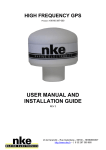
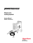
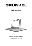
For Version 4.0 firmware
panels manufactured after
10/15/03
Congratulations
on your purchase!
INSTALLATION &
OPERATION
INSTRUCTIONS
FOR
ULTRA-8
EIGHT TANK
CAPABLE
DISPLAY
PANEL
You have selected the best holding tank
monitor system available. With proper
installation you will enjoy years of accurate
and trouble free operation.
E L E C T R O N I C S
1850 North Arthur
Pocatello, ID 83204
1-208-233-7290
You are a valued customer and we look forward to answering any questions
you may have regarding the installation or operation of this system.
This manual covers installation, adjustment and usage of the ULTRA-8
display panel.
TABLE OF CONTENTS
FEATURES
PAGE 2
INSTALLATION GUIDE
PAGE 3
CALIBRATION GUIDE
PAGE 8
TROUBLESHOOTING GUIDE
PAGE 10
PANEL CUSTOMIZATION
PAGE 13
WARRANTY INFORMATION
PAGE 14
PAGE 1
SNAKE RIVER ELECTRONICS
ULTRA - 8 DISPLAY PANEL
FEATURES/IMPROVEMENTS
This panel includes a number of new features and improvements over
our previous display panels, such as:
2 X 16 LCD display for tank designation, status and level.
Tank level read-out is a 10-position bar graph.
HI/LO/OK status indicator displayed for each tank.
Simple user interface.
Simplified push-button calibration with on-screen instructions.
Panel independently checks all tanks every 2 hours.
Red warning light to indicate when any tank is out-of-bounds (i.e., a
waste water tank is too full or a fresh water tank is too low).
Audible warning chirp sounds every 2 hours to indicate when any tank
is out- of- bounds (audible alarm is automatically disabled at night)
Panel can be used to monitor up to 8 separate tanks.
This panel is designed to interface with all of our existing sensors
allowing waste water, fresh water, in-tank rods and diesel fuel tanks to be
monitored.
ONE CAN
ADHESIVE
PAGE 2
INSTALLATION GUIDE
This kit includes an Ultra-8 panel and wiring harness
HIGH / LOW
INDICATOR
TANK
SYSTEMS
MONITOR
C
acu gage
ON
POWER
OFF
ONE
PANEL
ULTRA-8
WIRING
HARNESS
Typical sensor kit (sold separately):
SENSOR
MODULE
(STYLE MAY VARY)
ONE ROLL
FOIL TAPE
PAGE 3
If you purchased your sensor kit as an aftermarket kit,
it may also include the following (refer to the owners manuals
for the sensor(s) that you have purchased):
ONE
FUSELINK
UP TO 21- BUTT
CONNECTORS
YOU WILL NEED TO PROVIDE:
A. 18 Gauge Hookup Wire
B. 4 Screws To Secure Panel
You will also need sensor kits (sold separately) appropriate for the
type(s) of tanks you have in your vehicle.
PAGE 4
STEP ONE:
Location and Installation of Monitor Panel
NOTE: READ CAREFULLY
Choose a panel location that is convenient to see and reach, and that does not
interfere with drawers, cabinets, existing wiring, etc. In choosing a location you must also
give major consideration to the fact that wires must be routed from the panel to the holding
tanks. MAKE CERTAIN the proposed wiring routes are not blocked by the wall stringers or
other structural supports.
REFER TO FIGURE #1 and cut the panel opening as indicated. The panel will attach
to the wall with 4 screws (not included) at the corners. Do no attach the panel to the wall
until all other installation, calibration and testing has been completed.
FIGURE #1
Panel Cutout
3 1/8 “
6 1/8“
STEP TWO:
Install Sensors Onto The Tank(s)
Refer to owners manuals/installataion guides for the types of sensors that you are
going to be installing. Follow the instructions for all sensors to be installed then return to
this guide for the completion of wiring to the Ultra-8 display panel.
PAGE 5
STEP THREE:
Wiring Installation
NOTE: READ CAREFULLY. DO NOT use staples or nails to secure wiring. Route
wires so they do not interfere with storage areas and are away from potential sources of
heat (oven, exhaust pipes, etc.). Due to the vast range of application possibilities it is not
practical for us to include hookup wire in the kit. It is , however, commonly available and
inexpensive. Use 18 gauge standard wire and make certain you have enough to make all
connections.
The hookup wire is used to make connections to a 12 volt D.C. power source and for
connecting the panel to the tank(s). After studying the wiring installation procedures, cut
the hookup wires to required lengths, strip the insulation off all wire ends approximately
1/4“ and use the supplied butt connectors to join wires between pigtail and modules.
A. Take time to study Figure #3 and the “HOOKUP GUIDE” on the following page..
The first connections are made to wires 3 and 4 of the pigtail wire. IMPORTANT: The other
ends of these wires must also be identified as 3 and 4 ( use an adhesive sticker or masking
tape). These wires are then routed to the holding tank and wire 4 will connect to the red
module lead and wire 3 will connect to the blue module lead. Repeat this procedure for all
attached sensor modules insulate the ends of any unused panel connector leads (except
black and red) with electrical tape..
B. Refer to Figure #2 below and finish wiring by connecting wire 1 (red) to 12 volt
D.C. Positive, then wire 2 (black) together with all black module wires to 12 Volt D.C.
Negative. If you are using more than one module, use the larger wire nut to accommodate
the extra wires. NOTE: it is recommended that the power wires (red and black) be hooked
to a battery voltage source. The 0.5 amp fused link is wired in line on the red wire as
shown in Figure #2.
If possible, avoid wiring to a convertor power source or to wires that power
flourescent lights. This could result in electrical “noise” which may effect accurate panel
readings.
12 V. D.C. Power
NEG
POS
FIGURE
#2
FUSED LINK
Wire 1 (Red)
From Panel
Wire 2 (Black)
From Panel
Black Wire From
Each Module Used
PAGE 6
FIGURE #3
HIGH / LOW
INDICATOR
TANK
SYSTEMS
MONITOR
C
acu gage
ON
POWER
ULTRA-8
OFF
P
I
G
T
A
I
L
Wire 18
Wire 1
Panel Connector
Panel
COLOR CODE AND HOOK-UP GUIDE
DESCRIPTION
TANK ONE
TANK TWO
TANK THREE
TANK FOUR
TANK FIVE
TANK SIX
TANK SEVEN
TANK EIGHT
GROUND - BLACK
PIGTAIL WIRE
BLUE
PURPLE
YELLOW
ORANGE
GREEN
GREY
BROWN
WHITE
BLUE/WHIT
PINK
RED/WHITE
BLACK/WHITE
GREEN/WHITE
PURPLE/WHITE
BROWN/WHITE
ORANGE/WHITE
12 VOLT - RED
PAGE 7
MODULE WIRE
BLUE
RED
BLUE
RED
BLUE
RED
BLUE
RED
BLUE
RED
BLUE
RED
BLUE
RED
BLUE
RED
CALIBRATION GUIDE
When installation of the system is complete, it is necessary to calibrate each tank for
empty and full. Tools are not required to perform calibration.
The first step is to empty the tank of fluid. To enter calibration mode turn panel off,
press and hold in the “C” button, then while continuing to hold “C” turn the panel back on
(you may now release the “C” button). You will see the following screen:
CHAN:1
E:000
RAW:000
F:000
CHAN indicates the sensor channel number being displayed (numbered 1-8), RAW
indicates the raw sensor value being read by the panel from this sensor channel (a number
from 000-255), E indicates the currently set empty calibration point (000-255), and F
indicates the currently set full calibration point (also 000-255). You will also hear a beep
and see the red warning LED light up about every second, this indicates that the panel is
reading the sensor and updating the RAW value.
Scroll through the tanks using the up and down arrow keys until the desired tank
channel is displayed. To calibrate this channel, press the “C” key. The display will prompt
you to press the up-arrow key for a full tank, the down-arrow key for an empty tank or
the “C” key to end.
Calibrate
C = End
= Full
= Empty
To calibrate the tank to empty, press the down-arrow key. Next, the display will
read, “Are You Sure?” Press the up-arrow for “YES”, or the down arrow for “NO”
C
Are You Sure?
= Yes
= No
By pressing the up-arrow the panel will read the current tank level and store it as
empty.
To calibrate a tank for full, completely fill the tank with fluid. Follow the above
procedure, except, press the up-arrow key for full when prompted. Repeat this procedure for
all tanks attached to display panel.
If you calibrate the tank incorrectly ( i.e., calibrate an empty point that is above the
full point, or a full point below the empty point, or identical full and empty points), the
monitor panel indicates this to you with an error message and prompts you to recheck the
tank level and try again.
Error - Re-Check
And Try Again
PAGE 8
CALIBRATION GUIDE
(Continued)
Note: if the error message on the previous page is encountered, default calibration
values for empty and full are recorded in the memory of the panel. These values correspond
to a sensor output of 0VDC (zero) for empty and 3VDC for full and are displayed as E:000
F:153. These values are identical to the initial values programmed into the display panel
when it was first tested at the factory. This return to default values clears possible bad
calibration data which might make the sensor channel difficult to properly calibrate (i.e.: an
empty calibration value erroneously set with a full tank would otherwise prevent the setting
of a proper full value until the empty point is set back to an appropriate empty value).
The return to default calibration values will be “in the ballpark” with regard to
accuracy for most sensors, but for maximum accuracy empty and full calibration will need
to be performed for a tank when the above error message is seen.
PAGE 9
TROUBLESHOOTING GUIDE
Factors affecting accuracy of readings and calibration:
The unit should be calibrated with the vehicle as close to level as possible. Depending
on where the sensor strips are located on the tank, the reading may be somewhat sensitive
to the pitch of the vehicle (due to fluid sloshing either against or away from the sensor
elements mounted to the tank wall). Keep this in mind when interpreting what otherwise
might be a malfunctioning sensor or display.
Some tanks, particularly those mounted below the decks in boats, may be impossible
to completely drain or may refill with a small amount of fluid after pumping out (due to fluid
left in the drain plumbing, which may drain back into the tank). If you calibrated empty on
such a tank when it was completely dry (as in a factory installation) it may read that there
is some fluid in the tank even when pumped empty. If this is the case simply recalibrate the
empty point after pumping out and allowing to"settle" to an actual "empty” level.
PROBLEMS & REMEDIES
Problem:
Panel does not appear to retain calibration values.
Possible cause:
Damaged memory chip
Test/remedy:
Turn main power switch off. Press in both up and down arrow buttons and while holding
them in, turn the power back on. The panel will display the following:
FLASH MEM TEST
IN PROGRESS
This indicates that the panel has entered a special diagnostic mode which tests the memory
(do not turn power off to the panel until the test is complete or loss of one or more
calibration values is possible).
If the test is a failure, the following is displayed:
FLASH MEM TEST
MEM BAD : REPLACE
If the above message is displayed, contact Snake River Technical Support to arrange for the
repair of your display.
If the test is successful, the following is displayed:
FLASH MEM TEST
MEMORY GOOD
If the above message is displayed, the memory has checked out fine and the problem lies
elsewhere. Try recalibrating the troublesome tank for empty and full. If this does not
correct problem, contact Snake River Technical Support for additional instructions.
PAGE 10
Problem:
Panel does not turn on with power switch.
Test / Remedy:
Check fuse on power wire. If bad, replace. Check that power and ground wires are properly
attached. Repair, if necessary. If either or both of these do not fix the problem contact
Snake River Technical Support for additional instructions.
Problem:
A tank channel always reads full, empty or never changes regardless of level of fluid in the
tank.
Possible Causes:
1) improperly calibrated tank
2) damaged wiring between the display and sensor module
3) damaged or improperly installed sensor foil
4) damaged sensor module
Test/Remedy:
1) Recalibrate tank for empty and full and recheck. See following page for additional advice
on resetting calibration values for a channel to factory default values.
2) Check all of the wire between the sensor module and the display panel. Check that all
wires are attached properly and that there is no damage along the wire run (staples
through wires are a common problem to look for). Repair any problems found and recheck.
3) Check that the sensor foil is installed according to the instructions in this book. Also
check that there is nothing "shorting out" the sensor foils (i.e.: metal object touching both
foils), or that a large metal object is too close to the foils.
Finally, check that the white
wires attached to the sensor module have not come unattached from the aluminum sensor
foil. Correct any problems found.
4) If you have checked the wiring and sensor foil and nothing appears incorrect and if you
have recalibrated the tank and it is still not reading correctly, the sensor module on the tank
itself may be dammaged. You can look at the live output from the module in the calibration
mode (see calibration section of this manual for how to enter this mode). You will see a
screen like this:
CHAN:1
E:000
RAW:000
F:000
The 3 digit number at the upper right of the screen shows the raw sensor output of the
channel identified on the upper left of the screen (scroll up or down with the arrow keys
until the tank you are interested in is displayed). The output for an empty tank should be
between 000 and 50; a full tank should read between 150 and 200. If the readings do not
change or are well outside of the values given here ,contact Snake River Technical Support
for additional instructions or to arrange for a replacement sensor module to be sent to you.
PAGE 11
Problem:
A calibration value is entered which is incorrect on a sensor channel which is otherwise
working normally (i.e. an empty calibration value which is too high or a full value which is
too low).
Possible Causes:
1) improperly calibrated tank
Test/Remedy:
If practical to do so, drain the tank and set the empty calibration point then fill it and set
the full.
If it is impractical to drain the tank and re-fill (i.e. a fuel tank), then the factory default
calibration values for the troublesome tank can be re-set.
By intentionally creating a calibration error (see page 8 in this manual) the firmware in the
Ultra-8 display panel will record default calibration values for both empty and full in its
memory. These values correspond to a sensor output of 0VDC (zero) for empty and 3VDC
for full. These values are identical to the initial values programmed into the display panel
when it was first tested at the factory. This return to default values clears possible bad
calibration data which might make the sensor channel difficult to properly calibrate (i.e.: an
empty calibration value erroneously set with a full tank would otherwise prevent the setting
of a proper full value until the empty point is set back to an appropriate empty value).
Creating this error can be done by simply setting the full calibration value then immediately
setting the empty calibration value (see calibration procedure on page 8 of this manual). By
doing this, you are trying to set identical empty and full values which the Ultra-8 firmware
will not allow, and you should see the error message depicted on page 8. Once the error
message is displayed the factory default calibration values for that tank are now set.
The return to default calibration values will be “in the ballpark” with regard to accuracy for
most sensors, but for maximum accuracy, empty and full calibration for the tank should be
done as practical to do so.
PAGE 12
PANEL CUSTOMIZATION
ULTRA-8 Panel custom design options:
Start- up splash screen can be customized with your own text message
(limited to 2 lines each 16 characters long).
1 to 8 tanks can be monitored.
Tank designations can be customized to match your configuration using
a two-word tank designation for each tank. These designations can be up
to six characters per word. (examples: Fresh Water, Waste Water, Fwd
Waste, Aft Waste, etc.).
Normal tank monitoring occurs every 2 hours; however, timing can be
changed to read in as short a time as 1 minute or as long as 4 hour
intervals.
Audible alarms can be enabled or they can be disabled for any tank or
disabled completely if audible alarms are not desired. Audible alarms can
also be enabled or disabled at night.
Call SNAKE RIVER ELECTRONICS or refer to the enclosed
customization order form or visit our web page, WWW.SNAKERIVER.ORG, for more details.
PAGE 13
LIMITED
WARRANTY
Snake River Electronics warrants this product to be free from defects in material and workmanship under normal use for a period of one year from the date of purchase.
This includes the replacement of parts and the labor involved to repair or replace the part.
This warranty is valid for the original retail purchaser and is NOT TRANSFERABLE. Keep original sales receipt and validate warranty by filling out and returning the
enclosed warranty registration card. Proof of purchase is required to obtain warranty.
This warranty does not cover damages resulting from accident, misuse, abuse, improper installation, or lack of reasonable care. If the product was damaged in
transit, file a claim with the carrier.
Snake River Electronics is not responsible for incidental or consequential damages resulting from installation or use of product.
Except as provided above, no warranty or affirmation of fact, expressed or implied, is made or authorized by Snake River Electronics, and Snake River Electronics’
liability in all events is limited to the purchase price.
This warranty gives purchasers specific legal rights. Purchasers may also have rights which vary from state to state. Certain aspects of disclaimers are not
applicable to consumer products; e.g. (A) Some states do not allow the exclusion of limitation of accidental or consequential damages, so the above limitation or exclusion
may not apply to you, (B) Also, some states do not allow the exclusion or limitations on how long an implied warranty lasts, consequently the above limitation may not
apply to you; and copyright by law, during the period of this warranty, any implied warranties or merchantability of fitness for a particular purpose applicable to
consumer products purchased by consumers, may not be excluded or otherwise disclaimed.
PROMPT DISPOSITION: Snake River Electronics will make a good faith effort for prompt correction or other adjustments with respect to any Acugage Monitor
System which proves to be defective within warranty.
WARRANTY PROCEDURE: Should you discover a defect in the Acugage Monitor System during the warranty period, YOU MUST FIRST CONTACT SNAKE RIVER
ELECTRONICS AT 208-233-7290. At our discretion we will request the part be sent to us or we may direct you to the nearest authorized service center for repair. Parts
returned to Snake River Electronics must be postage paid, and include check or money order for $7.00 to cover the cost of return shipping and handling. RETURN TO:
Snake River Electronics, 1850 North Arthur Pocatello, ID 83204.
PAGE 14