1
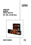
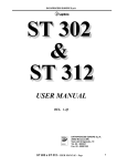
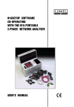
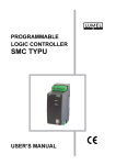
MEASURING PANELS WITH MULTICOLOUR BARGRAPHS DB2 SERIES USERS MANUAL MEASURING PANELS WITH MULTICOLOUR BARGRAPHS - DB2 SERIES USERS MANUAL CONTENTS 1. APPLICATION ..................................................................................................... 5 2. PANEL SET ......................................................................................................... 5 3. BASIC REQUIREMENTS, OPERATIONAL SAFETY ......................................... 5 4. DESIGN DESCRIPTION AND INSTALLATION .................................................. 7 5. ELECTRICAL CONNECTIONS ........................................................................... 9 6. DB2 PANEL FUNCTIONS ................................................................................ 10 6.1. CONNECTION CONFIGURATION - SETTING OF SERIAL PORT PARAMETERS .... 11 6.2. CHANGE OF CONNECTION PARAMETERS BETWEEN THE PANEL AND THE COMPUTER .............................................................................................. 12 6.3. PANEL IDENTIFICATION ........................................................................................... 12 6.4. REAL-TIME CLOCK ................................................................................................... 13 6.5. DATA READOUT FROM EXTERNAL DEVICES ....................................................... 13 6.6. DIAGNOSTIC REGISTERS ....................................................................................... 15 6.7. BRIGHTNESS CONTROL ......................................................................................... 15 6.8. MONITORING ............................................................................................................ 16 7. INTERFACE ...................................................................................................... 17 7.1. REGISTER MAP OF THE DB2 PANEL ..................................................................... 17 8. SPECIFICATIONS ............................................................................................. 25 9. ORDERING CODES .......................................................................................... 27 10. BEFORE A FAILURE WILL BE DECLARED ................................................... 28 11. MAINTENANCE AND GUARANTEE ............................................................... 29 ! " 1. APPLICATION Measuring panels with multicolour bargraphs have inputs destined to measure temperature and standard signal: d.c. voltage and d.c. current. The input can be also an RS-485 digital signal to connect transducers of physical quantities. These panels can find application in various industrial fields, e.g. food industry, environmental engineering, weather stations. They are destined to visualise measured quantities and evaluate change trends of supervised technological processes. They can find application in automation systems where programmed controllers are installed. Situated in a visible place, information helps in the efficient work of technological, logistic, sales and quality inspection teams. Panels display information in the shape of a multicolour bargraph where the readout field can assume colours: red, green or yellow. Colour change is defined in 5 thresholds. Measuring panels with multicolour bargraphs of DB2 type co-operate with external measuring devices equipped with RS-485 interface with MODBUS RTU protocol. It is possible to visualise technological processes, transmit messages from devices about the link state or the programmed quantity exceeding. The basic panel version includes two, three or four multicolour bargraphs. Inputs are the combination of 4 kinds of inputs: digital, Pt100, 4...20 mA and 0...10 V. After agreeing with the manufacturer it is possible to realise individual, custom-made projects. 2. PANEL SET The panel set is composed of: - DB2 measuring panel ........................ - DB2-Configurator software ............. - Assembly jigs ..................................... - Users manual ................................... - Guarantee card ................................. 1 pc 1 pc 2 pcs 1 pc 1 pc 3. BASIC REQUIREMENTS, SAFETY INFORMATION Symbols located in this users manual mean: ! ? WARNING! Warning of potential, hazardous situations. Especially important. One must be familiar with this before connecting the panel. The non-observance of notices marked by these symbols can occasion severe injuries of the personnel and the damage of the panel. CAUTION! Designates a general useful note. If you observe it, handling of the panel is made easier. One must take note of this, when the panel is working inconsistently to the expectations. Possible consequences if disregarded ! In the security scope the panelmodule meets the requirements of the EEC Low-Voltage Directive EN 61010-1 # Remarks concerning the operator safety: ! 1. General l The panel is destined to co-operate with other devices. l Non-authorized removal of the required housing, inappropriate use, incorrect installation or operation creates the risk of injury to personnel or damage to equipment. For more detailed information please study the users manual. l All operations concerning transport, installation, and commissioning as well as maintenance must be carried out by qualified, skilled personnel and national regulations for the prevention of accidents must be observed. l According to this basic safety information, qualified, skilled personnel are persons who are familiar with the installation, assembly, commissioning, and operation of the product and who have qualifications necessary for their occupation. 2. Transport, storage Please observe the notes on transport, storage and appropriate handling. Observe the climatic conditions given in Technical Data. 3. Installation l The panel must be installed according to the regulation and instructions given in this users manual. l Ensure proper handling and avoid mechanical stress. l Do not bend any components and do not change any insulation distances. l Do not touch any electronic components and contacts. l Electronic devicesmay contain electrostatically sensitive components, which can easily be damaged by inappropriate handling. l Do not install panels outside buildings l Do not damage or destroy any electrical components since this might endanger your health! 4. Electrical connection l Before switching the panel on, one must check the correctness of connection to the network. l In case of the protection terminal connection with a separate lead one must remember to connect it before the panel connection to the mains. l When working on live panels, the applicable national regulations for the prevention of accidents must be observed. l The electrical installation must be carried out according to the appropriate regulations (cable cross-sections, fuses, PE connection). Additional information can be obtained from the users guide. l The documentation contains information about installation in compliance with EMC (shielding, grounding, filters and cables). These notes must be observed for all CE-marked products. l The manufacturer of the measuring system or installed devices is responsible for the compliance with the required limit values demanded by the EMC legislation. l One must protect unused wires and terminals against their incidental touch. $ 5. Operation l Measuring systems including DB2 measuring panels must be equipped protection devices according to the corresponding standard and regulations for prevention of accidents. l After the panel has been disconnected from the supply voltage, live components and power connections must not be touched immediately because capacitors can be charged. l The housing must be closed during operation. l The sockets serve only to connect the interfaces (Fig. 4) 6. Maintenance and servicing. Please observe the manufacturers documentation. Read all product-specific safety and application notes in this users manual. l Before taking the panel housing out, one must turn the supply off. l The removal of the panel housing during the guarantee contract period may cause its cancellation. 4. DESIGN DESCRIPTION AND INSTALLATION The panel housing is made of aluminium. The safety degree ensured by the housing is IP40. Panel dimensions depending of versions are presented in the table 1. The panel has two jigs enabling the suspension or the assembly on a wall. 250 mm 250 mm 200 200 100 100 0 0 -100 -100 -200 -200 -250 -250 Fig. 1 DB2 panel % a c 250 mm 250 mm 200 200 100 100 0 0 -100 -100 -200 -200 -250 -250 h 74 b 60 L 8,6 Fig. 2 Panel dimensions, holes and fixing holder arrangement & 15° 20° Fig. 3 Panel suspension Fig. 4 Panel fixing on a wall Table 1 Panel type Readout field Panel overall dimensions (a ´ b ´ c ´ h) [mm] Spacing of fixing holes [mm] (L) 01 2 bargraphs 449 ´ 94.5 ´ 168.5 ´ 552 399 02 3 bargraphs 649 ´ 94.5 ´ 168.5 ´ 552 599 03 4 bargraphs 849 ´ 94.5 ´ 168.5 ´ 552 799 Panel dimensions, arrangement of holes and fixing holders 5. ELECTRICAL CONNECTION Two connection boxes are situated on the rear side of the panel. The upper box serves to connect the mains to the panel. The lower box is destined to connect control signals and the PC computer in order to configure and monitor the panel. For the connection with the computer, one must use a shielded conductor ended on both sides by a pin of DB9 type. This conductor should have a simple connection of end pins (without wire crossings) Description of pins on the RS-485 link. Signals on the link: 1-B 1 2 3 4 5 2-A 6 7 8 9 5 - GND Housing - conductor shield Electrical connections must be carry out in accordance with the Fig. 5 ' RS-485 + Input 1 - Bargraph 1 + Input 2 - Bargraph 2 + Input 3 - Bargraph 3 + Input 4 - Bargraph 4 Supply RS-485 Fig. 5 Electrical connections In order to facilitate the assembly, all terminals are described on the housing ? To carry out the interface installation a double wire spiral in a shield is recommended. Connect the shield to The PE terminal. Note: All panel communication connections should be carried out when the supply is switched off. Before switching the panel, it is recommended to check the assembly correctness in respect of terminal colouring preservation and corresponding signals to them, in accordance with above fig. 5. 6. DB2 PANEL FUNCTIONS The DB2 Configurator software is destined to configure the DB2 bargraph panel according to users requirements. After starting the DB2 Configurator software, the main software window is displayed. In the main software window, the user has the possibility to configure and start dialogues destined to: - configure the serial transmission port in the PC computer, - change connection parameters between the panel and the computer, - configure the panel brigthness. - set the date and time on the DB2 panel, - configure slave devices connected to the DB2 panel, - read out and display the DB2 panel state, - display information about the software, - display and start the panel monitoring. Moreover, on the main software window, buttons are placed to: - write the serial port configuration into the file, - read out the DB2 panel configuration, - write the DB2 panel configuration. Fig. 6 Main window of the DB2-Configurator software 6.1. Connection configuration - setting of serial port parameters The configuration of transmission parameters is carried out in the dialog window presented on the fig. 7. The panel has a large range of serviced baud rates for both communication interfaces: from 2400 b/ s up to 115200 b/s. In order to establish the communication with the panel, the user must define: - serial port which the panel is connected to, - type of transmission frame, - connection baud rate, - waiting for answer, - DB2 panel address, The introduction of an incorrect value is signalled by the software with request to correct the value of the given wrong parameter. Note: The panel is configured by default to work with the 8n2 frame and a baud rate equal to 9600 bit/sec. The default address is the address 1. Fig. 7 Serial port configuration 6.2. change of connection parameters between the panel and the computer The change of connection parameters between the computer and the panel can only take place when the serial port in the computer is correctly configured. In order to change transmission parameters, one must start the Connection change dialog. One must give required transmission parameters in the dialog (new transmission parameters). After pressing the apply button, the parameter transmission change will follow, what will be confirmed by the panel identifier display. 6.3. Panel identification The panel identification serves to display information about the panel and check the connection with the panel. For identification, the 17 MODBUS function is used. The selected System\Identification option from the menu occasions the data readout from the DB2 panel and the information window display (only in the case if there is no transmission errors) The response to the identification command causes the transmission by DB2 of the identifier and panel dimension with the number of matrix and point resolution. Fig. 8 Change of transmission parameters Fig. 9 Identification window 6.4 Real-time clock The DB2 panel has an internal real-time clock with the function to support the clock in case of supply decay and change automatically the summer time into the winter time, and inversely. The DB2- Configurator software allows to program the time when controlling the brightness time. The setting of the time and date is carried out in the Time and Date dialog window. One can set the time and date in two ways: - by the manual writing of time and date and pressing the Write push, - by pressing the synchronise push, what occasions the transmission of the time and date from the PC computer to the panel. Fig 10. Setting the date and time 6.5. Data readout from external devices For data readout from external devices ( e.g. measuring devices), an extra RS-485 interface with the MODBUS RTU protocol is foreseen. The transmission parameter configuration and readout parameter configuration to/from external devices is carried out by pressing the Slave configuration button. The user must enter in the displayed dialog, transmission parameters on the object page and give data parameters read out from devices. ! Fig. 11. Configuration of transmission parameters with slave devices Fig. 12 Configuration of data read out from slave devices The configuration of read out parameters (displayed data) includes following parameters: - device address - defines the register in the device, which data are to be read out from, - basic register - defines the register in the device, which data are to be begun from, - number of registers - defines how many registers are to be read out from the device. The number of registers must be included in the range from 1 to 10, - control register number - defines which from the read out register series is to be displayed on the panel in the bargraph shape, - register type - defines which type of registers are in the device which the readout will be carried out from, - scroll period - defines the period of query transmission though the DB2 panel to the slave device. " 6.6 Diagnostic registers Built-in diagnostic registers informing about the controller state and events. The DB2-Configurator software enables the review of diagnostic registers. In the base of presented messages, the user can state what events had occurred and what is the panel state. The selection of the Delete option causes the delete of the event flag after pressing the close button. Fig. 13 Status window 6.7. Brightness control The DB2 panel allows to define brightness changes. In order to define the brightness one should enter the time of day beginning and the time of night beginning, and define the brightness level for the day and night, expressed as the percentage of the maximal brightness. After entering mentioned parameters one can carry out the setting write for DB2 by pressing the Write settings button. Fig. 14 Setting the brightness on the time base # Fig.15 Setting the brightness on the base of the sunlight sensor During the panel operation with the sunlight sensor one must mark the Switch external sunlight sensor on field, then on the panel fields will be displayed to introduce the minimal and maximal brightness level which the panel is to reach at external lighting, suitably minimal and maximal. (the version with the sensor must be define in the order). 6.8. Monitoring The monitoring is started by pressing the Monitoring button on the task bar, what generates the start of the configuration data readout from the bargraph, and next the software switching over in the review mode of read out values and bargraph simulation. Fig 16. Monitoring window $ 7. INTERFACE The panel has the possibility to communicate with a computer of C class through the RS-232 or RS485 serial interface. The MODBUS RTU communication protocol has been implemented in the panel. Working modes: RTU8n2, RTU8n1, RTU8e1, RTU8o1. The baud rate encloses the range from 2400b/s up to 115200 b/s. Register values are of unsigned integer type. The word in the register is placed in older byte, younger byte sequence. 7.1. Register map of the DB2 panel with multicolour bargraphs Applied designations: R - readout W - write Configuration registers are 16-bit registers of unsigned integer type. Table 2 Register Operations address Range Description 4000 RW 1... 247 Interface No 1 address - Users interface 4001 RW 0... 3 Working mode of the interface number 1: 0: RTU 8N1 1: RTU 8N2 2: RTU 8E1 3: RTU 8O1 4002 RW 0... 9 Baud rate of the interface No 1[b/s]: 0 - 2400; 1 - 4800; 2 - 9600; 3 - 14400; 4 - 19200; 5 - 28800; 6 - 38400; 7 - 57600; 8 - 76800; 9 - 115200 4003 RW 1... 50 Waiting time to the slave device response for the port 2, expressed as the multiple of 100 ms. 4004 RW 1... 3 Working mode of the interface No 2: 0: RTU 8N1 1: RTU 8N2 2: RTU 8E1 3: RTU 8O1 4005 RW 1... 9 Baud rate of the interface No 2[b/s]: 0 - 2400; 1 - 4800; 2 - 9600; 3 - 14400; 4 - 19200; 5 - 28800; 6 - 38400; 7 - 57600; 8 - 76800; 9 - 115200 4006 RW 0... 2359 4007 RW 1... 99 4008 RW 101... 1231 Current time in the hour.100 + minutes format. The time write causes the automatic reset of secondes. Current year in the RR format Current datein the month. 100 + day format. % cd. Tablica 2 4009 RW 1... 100% Panel brightness level for day. Used at switched sunlight sensor off. Brightness control on the time base. 4010 RW 1... 100% Panel brightness level for night. Used at switched sunlight sensor off. Time control of brightness. 4011 RW 0... 2359 Hour of day beginning - Beginning of the day for the brightness time control. Time in the hour.100 + minutes format. 4012 RW 0... 2359 Hour of night beginning - Beginning of the night for time control of brightness. 4013 RW 1... 415 The real dimension in the panel is expressed as the number of matrix in vertical - y_matrix and number of matrix in horizontal -x_matrix. The dimension is calculated as: y_matrix.100 + x_matrix Note: one matix is equal 8 x 8 points. 4014 RW 0, 1 Bargraph direction: 0 - vertical bargraph 1 - horizontal bargraph 4015 RW 0, 1 External sunlight sensor: o - lack, 1 - installed 4016 RW 1... 100% Minimal brightness level - defines the minimal level of the brightness when working with the external sunlight sensor. 4017 RW 1... 100% Maximal brightness level - defines the maximal level of the brightness when working with the external sunlight sensor. 4018 RW 1... 100% Current level of the panel brightness. 4019 RW 0, 1 Signalling of bargraph trend: 0- OFF, 1- ON 4020 RW 0, 1 Signalling of minimal value: 0- OFF, 1- ON 4021 RW 0, 1 4022 RW 0... 2 Colour of the first interval: 0-green, 1-red, 2-yellow 4023 RW 0... 2 Colour of the second interval: 0-green, 1-red, 2-yellow 4024 RW 0... 2 Colour of the third: 0-green, 1-red, 2-yellow BARGRAPH 1 Signalling of maximal value: 0- OFF, 1- ON 4025 RW 0... 2 Colour of the fourth interval: 0-green, 1-red, 2-yellow 4026 RW 0... 2 Colour of the fifth interval: 0-green, 1-red, 2-yellow 4027 RW 0... 4 Number of the bargraph controlling device.c BARGRAPH 2 4028 RW 0, 1 Signalling of bargraph trend: 0- OFF, 1- ON 4029 RW 0, 1 Signalling of minimal value: 0- OFF, 1- ON & cd. Table 2 4030 RW 0, 1 Signalling of maximal value: 0- OFF, 1- ON 4031 RW 0... 2 Colour of the first interval: 0-green, 1-red, 2-yellow 4032 RW 0... 2 Colour of the second interval: 0-green, 1-red, 2-yellow 4033 RW 0... 2 Colour of the third: 0-green, 1-red, 2-yellow 4034 RW 0... 2 Colour of the fourth interval: 0-green, 1-red, 2-yellow 4035 RW 0... 2 Colour of the fifth interval: 0-green, 1-red, 2-yellow 4036 RW 0... 4 Number of the bargraph controlling device. 4037 RW 0, 1 BARGRAPH 3 Signalling of bargraph trend: 0- OFF, 1- ON 4038 RW 0, 1 Signalling of minimal value: 0- OFF, 1- ON 4039 RW 0, 1 Signalling of maximal value: 0- OFF, 1- ON 4040 RW 0... 2 Colour of the first interval: 0-green, 1-red, 2-yellow 4041 RW 0... 2 Colour of the second interval: 0-green, 1-red, 2-yellow 4042 RW 0... 2 Colour of the third: 0-green, 1-red, 2-yellow 4043 RW 0... 2 Colour of the fourth interval: 0-green, 1-red, 2-yellow 4044 RW 0... 2 Colour of the fifth interval: 0-green, 1-red, 2-yellow 4045 RW 0... 4 Number of the bargraph controlling device. 4046 RW 0, 1 BARGRAPH 4 Signalling of bargraph trend: 0- OFF, 1- ON 4047 RW 0, 1 Signalling of minimal value: 0- OFF, 1- ON 4048 RW 0, 1 Signalling of maximal value: 0- OFF, 1- ON 4049 RW 0... 2 Colour of the first interval: 0-green, 1-red, 2-yellow 4050 RW 0... 2 Colour of the second interval: 0-green, 1-red, 2-yellow 4051 RW 0... 2 Colour of the third: 0-green, 1-red, 2-yellow 4052 RW 0... 2 Colour of the fourth interval: 0-green, 1-red, 2-yellow 4053 RW 0... 2 Colour of the fifth interval: 0-green, 1-red, 2-yellow 4054 RW 0... 4 Number of the bargraph controlling device. BARGRAPH 5 4055 RW 0, 1 Signalling of bargraph trend: 0- OFF, 1- ON 4056 RW 0, 1 Signalling of minimal value: 0- OFF, 1- ON 4057 RW 0, 1 Signalling of maximal value: 0- OFF, 1- ON 4058 RW 0... 2 Colour of the first interval: 0-green, 1-red, 2-yellow 4059 RW 0... 2 Colour of the second interval: 0-green, 1-red, 2-yellow 4060 RW 0... 2 Colour of the third: 0-green, 1-red, 2-yellow 4061 RW 0... 2 Colour of the fourth interval: 0-green, 1-red, 2-yellow 4062 RW 0... 2 Colour of the fifth interval: 0-green, 1-red, 2-yellow ' cd. Table 2 4063 RW 0... 4 Number of the bargraph controlling device. Status register, bits present event flags or errors: Bit 15 - SRAM memory error, Bit 14 - EEPROM memory error, Bit 13 - setting error of the RTC clock or unreliable settings, Bit 12 - summer/winter time has been changed or inversely, Bit 11 - error of the external sunlight sensor (set only in case when the sensor is switched on), 4064 RW 0... 65535 Bit 10 - supply break - flag set in case of supply decay, Bit 9 - delete bargraph minimum and maximum, Bit 8..5 - no used, Bit 4 - communication error with the slave device No 5 Bit 3 - communication error with the slave device No 4 Bit 2 - communication error with the slave device No 3 Bit 1 - communication error with the slave device No 2 Bit 0 - communication error with the slave device No 1 Registers of data readout configuration from external devices - registers 4300...4329 All configuration registers are 16-bit registers of unsigned integer type. Table 3 Register Operations address Range Description DEVICE 1 4300 RW 0...247 4301 RW 0...65535 Slave device address. 0 - readout off 4302 RW 1...10 Number of read out registers 4303 RW 0...6 Register type: Basic address 0 - variable of char type 1 - variable of unsigned char type 2 - variable of integer type 3 - variable of unsigned char type 4 - variable of lonf type 5 - variable of unsigned long type 6 - variable of float type 4304 RW 1...10 Register number steering the bargraph 4305 RW 1...60 Reviewing period in seconds. Defines the query frequency of the slave device. 4306 RW 0...247 Slave device address. 0 - readout off 4307 RW 0...65535 4308 RW 1...10 Number of read out registers 4309 RW 0...6 Register type: DEVICE 2 Basic address 0 - variable of char type 1 - variable of unsigned char type 2 - variable of integer type 3 - variable of unsigned char type 4 - variable of lonf type 5 - variable of unsigned long type 6 - variable of float type 4310 RW 1...10 Register number steering the bargraph 4311 RW 1...60 Reviewing period in seconds. Defines the query frequency of the slave device. cd. Table 3 DEVICE 3 4312 RW 0...247 Slave device address. 0 - readout off 4313 RW 0...65535 4314 RW 1...10 Number of read out registers 4315 RW 0...6 Register type: Basic address 0 - variable of char type 1 - variable of unsigned char type 2 - variable of integer type 3 - variable of unsigned char type 4 - variable of lonf type 5 - variable of unsigned long type 6 - variable of float type 4316 RW 1...10 Register number steering the bargraph 4317 RW 1...60 Reviewing period in seconds. Defines the query frequency of the slave device. DEVICE 4 4318 RW 0...247 4319 RW 0...65535 Slave device address. 0 - readout off 4320 RW 1...10 Number of read out registers 4321 RW 0...6 Register type: Basic address 0 - variable of char type 1 - variable of unsigned char type 2 - variable of integer type 3 - variable of unsigned char type 4 - variable of lonf type 5 - variable of unsigned long type 6 - variable of float type 4322 RW 1...10 Register number steering the bargraph 4323R W 1...60 Reviewing period in seconds. Defines the query frequency of the slave device. cd. Table 3 DEVICE 5 4324 RW 0...247 4325 RW 0...65535 Slave device address. 0 - readout off 4326 RW 1...10 Number of read out registers 4327 RW 0...6 Register type: Basic address 0 - variable of char type 1 - variable of unsigned char type 2 - variable of integer type 3 - variable of unsigned char type 4 - variable of lonf type 5 - variable of unsigned long type 6 - variable of float type 4328 RW 1...10 Register number steering the bargraph 4329 RW 1...60 Reviewing period in seconds. Defines the query frequency of the slave device. Configuration registers and values read out from external devices - registers 7500...7569 All registers are 32-bit registers of float type. Tablica 4 Register Operations address Range Description BARGRAPH 1 7500 RW n.d. Bargraph minimum 7501 RW n.d. 7502 RW 0...100% End of the first threshold as the percentage filling Bargraph maximum 7503 RW 0...100% End of the secong threshold as the percentage filling 7504 RW 0...100% End of third threshold as the percentage filling 7505 RW 0...100% End of the fourth threshold as the percentage filling 7506 RW n.d. BARGRAPH 2 Bargraph minimum 7507 RW n.d. 7508 RW 0...100% End of the first threshold as the percentage filling Bargraph maximum 7509 RW 0...100% End of the secong threshold as the percentage filling 7510 RW 0...100% End of third threshold as the percentage filling 7511 RW 0...100% End of the fourth threshold as the percentage filling ! cd. Table 4 BARGRAPF 3 7512 RW n.d. 7513 RW n.d. Bargraph minimum 7514 RW 0...100% End of the first threshold as the percentage filling 7515 RW 0...100% End of the secong threshold as the percentage filling 7516 RW 0...100% End of third threshold as the percentage filling 7517 RW 0...100% End of the fourth threshold as the percentage filling Bargraph maximum BARGRAPF 4 7518 RW n.d. Bargraph minimum 7519 RW n.d. 7520 RW 0...100% End of the first threshold as the percentage filling Bargraph maximum End of the secong threshold as the percentage filling 7521 RW 0...100% 7522 RW 0...100% End of third threshold as the percentage filling 7523 RW 0...100% End of the fourth threshold as the percentage filling 7524 RW n.d. BARGRAPF 5 Bargraph minimum 7525 RW n.d. Bargraph maximum 7526 RW 0...100% End of the first threshold as the percentage filling 7527 RW 0...100% End of the secong threshold as the percentage filling 7528 RW 0...100% End of third threshold as the percentage filling 7529 RW 0...100% End of the fourth threshold as the percentage filling DATA READ OUT FROM DEVICES DEVICE 1 7530 R n.d. ... ... ... DATA 0 ... 7539 R n.d. DATA 9 7540 R n.d. DATA 0 ... ... ... ... 7549 R n.d. DATA 9 7550 R n.d. ... ... ... ... 7559 R n.d. DATA 9 DEVICE 2 DEVICE 3 " DATA 0 cd. Table 4 DEVICE 4 7560 R n.d. ... ... ... DATA 0 ... 7569 R n.d. DATA 9 7570 R n.d. ... ... ... ... 7579 R n.d. DATA 9 DEVICE 5 DATA 0 8. SPECIFICATIONS Power consumption: - DB2-01 - DB2-02 - DB2-03 £ 60 VA £ 70 VA £ 110 VA Read-out field: - DB2-01 - DB2-02 - DB2-03 2 bargraphs, 51 three-coloured points 3 bargraphs, 51 three-coloured points 4 bargraphs, 51 three-coloured points Communication: -serial interface (DB2®PC) - serial interface (DB2® measuring device) digital input - protocol transmission RS-485 RS-485 MODBUS RTU Reaction to decay and supply return: - preservation of configuration data Protection degree ensured by the housing IP 40 Dimensions: depending on version (acc. to table 1) # Environmental and rated operating conditions: - working temperature 0... 23... 55°C - storage temperature -20... 75°C - humidity 25... 95% - supply 100...230... 240 V a.c. - frequency 45...50...60 Hz - external magnetic field 0...40...400 A/m - working position any Standards fulfilled by the panels: Electromagnetic compatibility: - immunity - emission - resistance against supply decay EN 61000-6-2 EN 61000-6-4 EN 61000-6-2 Safety requirements: acc. to EN 61010-1 standard l insulation ensured by the housing: basic l insulation between circuits: basic l insulation category III l pollution degree 2 l maximal phase-to-earth voltage: 300 V for supply 50 V for interface circuit $ 9. ORDERING CODES Measuring panel with multicolour bargraphs DB2 Table5 XX X X X X XX Panel type: with 2 bargraphs .............................................................. 01 with 3 bargraphs .............................................................. 02 with 4 bargraphs .............................................................. 03 on order .......................................................................... XX Bargraph 1 - Input type: Digital ........................................................................................ 0 Pt100 * ...................................................................................... 1 4...20 mA (range 0...100%) ..................................................... 2 0...10 V (range 0...100%) ..................................................... 3 Bargraph 2 - Input type: Digital ............................................................................................... Pt100* .............................................................................................. 4...20 mA (range 0...100%) ............................................................. 0...10 V (range 0...100%) ............................................................. 0 1 2 3 Bargraph 3 - Input type: Digital** .................................................................................................... 0 Pt100* ...................................................................................................... 1 4...20 mA (range 0...100%) .................................................................... 2 0...10 V (range 0...100%) .................................................................... 0 Bargraph 4 - Input type: Digital** ............................................................................................................ 0 Pt100* .............................................................................................................. 1 4...20 mA (range 0...100%) ............................................................................ 2 0...10 V (range 0...100%) ............................................................................ 3 Version: Standard ................................................................................................................ 00 custom-made ......................................................................................................... XX * Define the measuring range in the order ** For the DB2-01 type, accept 0 for channels 3 and 4 for the DB-02,type, accept 0 for the channel 4 % ORDERING EXAMPLE The code: DB2 01 2 1 0 0 00 (Pt100, from 10 to 60§C) means: DB2 - a measuring panel with multicolour bargraphs 01 - with 2 bargraphs 2 - 0...20 mA (0...100% range) input for the bargraph 1 1 - Pt100 signal (10...60oC range)input for the bargraph 2 0 - without the channel 3 0 - without the channel 4 00 - standard version The given range is also the bargraph graduation. Note: There is the possibility to order a measuring panel with an embedded sunlight sensor. DB2 communication Interface > PC RS-485, there is also the possibility to carry out with the RS232 interface. 10. BEFORE A FAILURE WILL BE DECLARED ? In case of incorrect symptoms please acquaint with the table below. Table 6 Symptoms 1. After the panel switching on, not any segment is displayed. Procedure Check the connection of the network cable. 2. Bargraph flickering in the place where the Transmission error, check the connection A, B value from the external device is to be and settings of the read out device (slave found. configuration) if they are consistent with settings of the device co-operating with the panel. 3. Bargraph flickering. Erroneous quantity range (100% overflow of the declared range to display). Correct the range by means of the DB2-Configurator software. 4. Lack of reliability whether all character fields are efficient. Carry out a repeated switching on. Make the panel test, and in case of abnormalities, contact an authorised workshop. 5. A result inconsistent with our expectations occurs on the readout field (result from the external device). Check in Slave configuration the register compatibility and the displayed register number. 6. The panel does not establish communica- Check the connection correctness and the correctness of introduced transmission parametion with the computer through RS-485 ters. and RS-232 interfaces. In case, when the user does not remember the set up transmission parameters, one must check them by means of the DB2-Configurator software. & 11. MAINTENANCE AND GUARANTEE The DB2 panel does not require any periodical maintenance. During the operation, a message about errors in the shape of bargraph flickering can occur when: - the value exceeds 100% of the range, - the digital connection between the panel and the measuring device is broken. Other messages are available after agreeing with the customer, in custom-made versions. 1. From the shipping date, during the period given in the annexed guarantee card One should take the panel down from the installation and return it to the manufacturers Quality Inspection Dept. If the unit has been used in compliance with the instructions, The manufacturer guarantees to repair it free of charge. 2. After the guarantee period: One should turn over the panel to repair it in a certified service workshop. The disassembling of the housing causes the cancellation of the granted guarantee. Spare parts are available for the period of five years from the date of purchase. LUMEL S.A. policy is one of continuous improvement and we reserve the right to make changes in design and specification of any products as engineering advances or necessity requires and revise the above specification without notice. ' ! ! SALES PROGRAM n DIGITAL and BARGRAPH PANEL METERS n MEASURING TRANSDUCERS n ANALOG PANEL METERS (DIN INSTRUMENTS) n ANALOG and DIGITAL CLAMP-ON METERS n INDUSTRIAL and HOUSEHOLD CONTROLLERS n CHART AND PAPERLESS RECORDERS n POWER CONTROL UNITS and INVERTERS n LARGE SIZE NUMERIC and ALPHANUMERIC DISPLAYS n AUTOMOTIVE DASHBOARD INDICATORS n ACCESSORIES FOR MEASURING INSTRUMENTS n MEASURING SYSTEMS (ENERGY, HEAT, CONTROL) n CUSTOM-MADE PRODUCTS MEASUREMENT CONTROL RECORDING WE ALSO OFFER OUR SERVICES IN THE PRODUCTION OF: n ALUMINIUM ALLOY PRESSURE CASTINGS n PRECISION ENGINEERING AND THERMOPLASTICS PARTS n PRESSURE CASTING DIES AND OTHER TOOLS QUALITY PROCEDURES According to ISO 9001 and ISO 14001 international requirements. All our instruments have CE mark . For more information, please write to or phone our Export Department May 2005 Lubuskie Zak³ady Aparatów Elektrycznych LUMEL S.A. ul. Sulechowska 1, 65-022 Zielona Góra, Poland Tel.: (48-68) 3295 100 (exchange) Fax: (48-68) 3295 101 e-mail:[email protected] http://www.lumel.com.pl Export Department: Tel.: (48-68) 3295 302 or 304 Fax: (48-68) 3254 091 e-mail: [email protected]