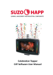
Download Celebration Topper
Transcript
Celebration Topper Part Number: RBM-754x-xx 8/20/2013 Celebration Topper Revised : 8/20/2013 4:25:00 PM- JL 2 OF 46 Celebration Topper Table of Contents 1. General......................................................................................................................... 5 1.1 Features ...............................................................................................................................................5 1.2 Part Numbers / Configuration Options ............................................................................................6 1.3 Assembly Dimensions .......................................................................................................................7 1.4 Electrical Connections .......................................................................................................................8 1.4.1 Celebration Topper Harness Diagram .....................................................................................8 1.4.2 Description of Electrical Connections.......................................................................................9 1.4.3 Electrical Pin-out Information...................................................................................................10 2. Set-up and Installation .............................................................................................. 12 2.1 Installation Procedure – Main Topper Assembly .........................................................................12 2.2 Removing the Bezel Assembly .......................................................................................................13 2.3 Installation / Replacement of Graphic Panel and Bezel Graphic ..............................................15 2.4 Removal of the LCD / Backlight Panel ..........................................................................................15 2.5 Installing / Replacing the Tower Light Color Foils .......................................................................16 2.6 LCD OSD Adjustments....................................................................................................................16 2.7 Media Player Set-up ........................................................................................................................17 2.7.1 Installing the compact flash card ............................................................................................17 2.7.2 Media Player Initial Set-up ......................................................................................................18 2.8 Main Control PCBA User Settings .................................................................................................27 2.8.1 Setting the Flashing Pattern Mode for the RGB LED Strip .................................................27 2.8.2 Setting the Color for the RGB LED Strip ...............................................................................27 2.9 SAS Handpay Interface PCBA User Settings ..............................................................................28 2.9.1 Location and Function of PCBA Components ......................................................................29 2.9.2 DIP switch settings ....................................................................................................................29 2.10 Installation and Replacement of Confetti Capsules ..................................................................32 2.11 RGB LED Strip Synchronization ..................................................................................................33 3. Operation ................................................................................................................... 34 Revised : 8/20/2013 4:25:00 PM- JL 3 OF 46 Celebration Topper 3.1 Controlling and Updating Media Content .....................................................................................34 3.1.1 Guidelines for Creating Media Content ..................................................................................34 3.2 Adjusting the Volume .......................................................................................................................35 4. Maintenance and Troubleshooting .......................................................................... 36 4.1 Cleaning the Acrylic Panel ..............................................................................................................36 4.2 Replacing the Tower Light Bulbs: ..................................................................................................36 4.3 Replacing the Confetti Launch Modules .......................................................................................36 5. Reference Information .............................................................................................. 38 5.1 Exploded Drawing / Replacement Parts List ................................................................................38 5.2 Wiring Diagram .................................................................................................................................40 5.3 Dimensions for Graphic Panel .......................................................................................................41 5.4 Dimensions for Bezel Graphic Panel ............................................................................................42 5.5 Topper Base Adapter Options........................................................................................................43 5.6 Compliance Information ...................................................................................................................45 Revised : 8/20/2013 4:25:00 PM- JL 4 OF 46 Celebration Topper 1. General 1.1 Features This innovative topper design creates a new level of excitement on your casino floor and stimulates additional game play Topper interfaces into the SAS line to detect a hand pay signal from the slot machine and when the selected level of hand pay is achieved the topper triggers a "Celebration Event" Celebration Event options include ANY or ALL of the following: • Confetti launcher throws out bursts of confetti • Loud 8 Watt Stereo audio celebration alarm/sounds thru two 2" x 4" speakers • Standard or customizable videos on the 15.6" LCD (1366 x 768 resolution) • Flashing multi-color RGB LED’s on both sides of the LCD 15.6" LCD driven by Network Digital Signage Player • 10/100M Ethernet with RJ-45 connector • Storage on Compact Flash (CF) card up to 32GB (sold separately - 96-0046-00 for 2GB) • NTP, FTP Client, HTTP Client • Download Performance over 300KBps with intranet HTTP server (CF Card: Sandisk Extreme IV) • Playback Formats : MPEG-1, MPEG-2, MPEG-4, Divx up to 720p • Audio Formats of WAV, MP3 (32k – 320k bps) • Image Format of JPEG (max resolution 5120x3840) • Remote Control – used for media player network setup for client IP, Server IP and other settings • Bundled Software for Windows XP/Vista to load, control and monitor client’s status and activity • RSS feed capable Includes several Celebration videos that can be further customized for fee by video production company Translucent bezel on sides of LCD contains 24 ultra-bright Nichia RGB LED's for a multi-colored light show Pre-programmed with unique flashing patterns and different color combinations Backlight graphic panel can be substituted in place of 15.6" LCD Front of video topper has ability for custom branded graphic to be inserted Confetti capsules are sold separately (95-0124-00) are spring loaded (safe – no Fireworks) and sprays over twenty color stripes with six colors and colorful effects for 13-19 feet (4-6 meters) in the air Body is constructed of black UL-94 VO flame resistant plastic Three different mounting base adapters available (sold separately) - Flat, Round, or Slant Tower light optional Patent Pending Revised : 8/20/2013 4:25:00 PM- JL 5 OF 46 Celebration Topper 1.2 Part Numbers / Configuration Options Celebration Topper Part Number Matrix* R B M - 7 5 4 x - x x Finishing Display S=Chrome 1 = 15.6" LCD K=Black 2 = LED Backlight Panel Option A = W/O Celebration Features C = Includes Confetti Tubes Only E = LCD and RGB LEDs Only F = LCD only Power Supply (2pcs needed for most configurations – sold seperately) RE251-669-01USA - POWER SUPPLY KIT USA FOR CELEBRATION TOPPER Compact Flash (sold separately – other size options are also available) 96-0046-00 - COMPACT FLASH 2GB * Configuration options shown here are subject to change. Please refer to the Suzo-Happ website for the latest information regarding available configuration options. Revised : 8/20/2013 4:25:00 PM- JL 6 OF 46 Celebration Topper 1.3 Assembly Dimensions Celebration Versions: Video Versions (no confetti launch modules): Revised : 8/20/2013 4:25:00 PM- JL 7 OF 46 Celebration Topper 1.4 Electrical Connections 1.4.1 Celebration Topper Harness Diagram Revised : 8/20/2013 4:25:00 PM- JL 8 OF 46 Celebration Topper 1.4.2 Description of Electrical Connections 12VDC – Main PCBA – Provides power to the Main Control PCBA. Necessary for all topper configurations 12VDC – LCD - Power connection to LCD, Media Player, Amplifier, and Celebration Interface PCBA. Optional depending upon configuration Grounding Terminal – Size #8 ring terminal connection for securing the topper ground connection to the game ground connection (earth ground) Tower Light – Connection to tower light / candle Network – Media player – RJ45 Ethernet connection to media player LED Sync (Male) – Optional synchronization connection for the side RGB LEDs. Allows synchronization of LED patterns that will continue from one topper to the next in the series LED Sync (Female) – Optional synchronization connection for the side RGB LEDs. Allows synchronization of LED patterns that will continue from one topper to the next in the series SAS (Host) – Connection from SAS Handpay Interface PCBA to SAS host system SAS (EGM) – Connection from SAS Handpay Interface PCBA to SAS connection on the EGM (Electronic Gaming Machine). Revised : 8/20/2013 4:25:00 PM- JL 9 OF 46 Celebration Topper 1.4.3 Electrical Pin-out Information NETWORK - MEDIA PLAYER PIN COLOR FUNCTION 1 - TX_D1+ 2 - TX_D1- 3 - RX_D2+ 4 - BI_D3+ 5 - BI_D3- 6 - RX_D2- 7 - BI_D4+ 8 - BI_D4- CONNECTOR TYPE RJ-45 P1 - 12VDC - MAIN PCBA PIN COLOR FUNCTION 1 ORG/GRN DC GND 2 RED +12VDC CONNECTOR TYPE MOLEX - 39-01-2021 P2 - 12VDC -LCD PIN COLOR FUNCTION 1 BLK DC GND 2 RED +12VDC CONNECTOR TYPE MOLEX - 39-01-2021 P3 - TOWER LIGHT PIN COLOR FUNCTION 1 BLK +V 2 YEL LAMP- 2ND FROM BOTTOM 3 WHT LAMP - BOTTOM 4 BLU LAMP - 3RD FROM BOTTOM CONNECTOR TYPE MOLEX - 03-09-2049 GROUNDING TERMINAL PIN COLOR FUNCTION CONNECTOR TYPE - GRN EARTH GROUND RING TERMINAL Revised : 8/20/2013 4:25:00 PM- JL 10 OF 46 Celebration Topper P4 - LED SYNC PIN COLOR FUNCTION 1 BLK GND 2 WHT TXD/RXD PIN COLOR FUNCTION 1 BLK GND 2 WHT TXD/RXD CONNECTOR TYPE - P5 - LED SYNC CONNECTOR TYPE - SAS HANDPAY INTERFACE- EGM PIN COLOR FUNCTION 1 - - 2 BRN RX 3 RED TX 4 - - 5 YEL GND 6 - - 7 - - 8 - - 9 - - CONNECTOR TYPE DE-9 (DB-9) MALE SAS HANDPAY INTERFACE- HOST PIN COLOR FUNCTION 1 - - 2 BRN TX 3 RED RX 4 - - 5 YEL GND 6 - - 7 - - 8 - - 9 - - Revised : 8/20/2013 4:25:00 PM- JL CONNECTOR TYPE DE-9 (DB-9) FEMALE 11 OF 46 Celebration Topper 2. Set-up and Installation 2.1 Installation Procedure – Main Topper Assembly Important: • Shut-off the power from the host machine until installation work is completed. • Power supply: 12VDC x 2pcs (depending upon configuration options) 5A minimum each. The topper can be mounted to a game cabinet by using the included base mount or by adding one of the optional base adapters. Please see section 5.5 of this manual for the part number and dimensional information of the various base options. 1. Prepare the mounting area on your game cabinet by drilling the appropriate holes and installing any necessary hardware (refer to mounting information provided for your particular mounting base). 2. If a base adapter is being used for your application, install to the topper base using the provided mounting hardware. Revised : 8/20/2013 4:25:00 PM- JL 12 OF 46 Celebration Topper 3. Place the topper on the top of the game cabinet and match the studs on the topper base to the holes in the cabinet. Secure the studs to the cabinet using the included hardware (M6 nut and washer x 2pcs). 4. Connect the power harnesses, and all other harnesses, as necessary for your particular configuration. 2.2 Removing the Bezel Assembly Removing the bezel assembly may be necessary for installation and set-up, depending upon your configuration. Removing the bezel assembly allows access to the LCD OSD (On Screen Display) control for setting adjustments, and also allows access to the IR receiver for remote control set-up / adjustments for the media player. Removal also allows access to the bezel assembly for installation or replacement of graphic panels. 1. Remove the bezel assembly mounting screws (M5 screws 2pcs) Revised : 8/20/2013 4:25:00 PM- JL 13 OF 46 Celebration Topper 2. Remove the bezel assembly from the main housing assembly. Note that it may be necessary to apply pressure at the top section of the bezel assembly in order to release the snap features holding the front bezel to the rear housing. Location of Components Revised : 8/20/2013 4:25:00 PM- JL 14 OF 46 Celebration Topper 2.3 Installation / Replacement of Graphic Panel and Bezel Graphic 1. Slide the bezel retaining clips in the direction as shown in order to release the bezel and clear acrylic panel from the bezel assembly. 2. Install/Replace the bezel graphic and/or backlight graphic panels as needed. 2.4 Removal of the LCD / Backlight Panel Removal of the LCD panel (or backlight panel) may be necessary for set-up, adjustment, or maintenance, depending upon your configuration. Removal of the LCD panel allows access to the Main Control PCBA, Amplifier PCBA, Media Player PCBA, SAS Handpay Interface PCBA, and all associated connectors. 1. Remove the panel mounting screws as indicated (M4 screws x 4pcs) 2. Unplug the connectors at the LCD / Backlight Panel, and remove the panel from the topper assembly Revised : 8/20/2013 4:25:00 PM- JL 15 OF 46 Celebration Topper Location of Components 2.5 Installing / Replacing the Tower Light Color Foils The Celebration Topper has been provided with a color foil kit that includes the most common color foils used in casinos per various jurisdictions. If you have special color foil requirements, or need replacement foils, please contact your Suzo-Happ representative. 1. Remove the M4 acorn nut at the top of the tower light. 2. Slide the top cap off in order to gain access to the top inner section of the tower light. If access is need to other sections, remove the clear outer tube and foil, and then slide the base platform and grounding ring from the mounting rod to gain access to the next section. 3. Once you have accessed the desired section, replace the color foil. Be sure that the edges of the color foil meet at the rear of the candle (side that has the mounting rod). 4. Reassemble the candle and replace the mounting nut on the top cap. 2.6 LCD OSD Adjustments As the exact LCD panel is subject to change, please refer to the separate LCD user guide for the details regarding the use of the OSD control Revised : 8/20/2013 4:25:00 PM- JL 16 OF 46 Celebration Topper 2.7 Media Player Set-up The Media Player Set-up refers to Celebration Toppers that include the optional media player. If your configuration does not include a media player, you can skip to the next section. 2.7.1 Note: Installing the compact flash card A compact flash card must be installed in order to use the media player. purchased separately, and can be supplied by Suzo-Happ. This card must be Please check with your Suzo-Happ representative to determine the appropriate flash card for your application. Important: 1. Remove power to the topper before installing or removing the compact flash card. Remove the media access panel at the bottom of the topper assembly by removing the retaining screw (M4 x 1pc). 2. Insert the compact flash card in the slot as shown. Pay careful attention to the orientation and alignment of the card when inserting into the slot. The compact flash card must be inserted with the label (top side) facing the front of the topper. If you feel any resistance when inserting the card, recheck the alignment and re-insert the card. Important: Improper installation may damage the media player and void the warranty. Revised : 8/20/2013 4:25:00 PM- JL 17 OF 46 Celebration Topper Note: If your compact flash is preformatted, please check to make sure it is formatted to a FAT32 file system. The media player will not work properly with other file system formats (FAT, exFAT, NTFS, etc.). If you want to check the formatting of your compact flash, it can be verified by connecting to a PC using a media card reader. Once the compact flash is recognized, right click on the drive letter for your compact flash, and select properties. The file system should be indicated. If you need to format to FAT32, then right click on the drive letter assigned for the compact flash and select format. FAT32. 2.7.2 In the options for format, be sure to select Note that any data that is on the compact flash will be erased during formatting. Media Player Initial Set-up 1. Remove the front bezel assembly. 2. Apply power to the topper and wait until the start-up screen is displayed on the LCD. 3. Enter the MAIN MENU - If the player is set for the default settings, the MAIN MENU will be shown at power-up. If the player is playing media content, the MAIN MENU can be entered by pressing STOP on the user remote, and then pressing MAIN MENU on the remote control. Select SETUP using the cursor keys on the remote, and select the option by pressing PLAY on the remote. Revised : 8/20/2013 4:25:00 PM- JL 18 OF 46 Celebration Topper 4. Set the Operation Mode - Select the OPERATION MODE from the SETUP MENU. The media player can be set for the following modes depending upon the desired function: Revised : 8/20/2013 4:25:00 PM- JL 19 OF 46 Celebration Topper CF CARD (default mode) – This mode allows for “stand alone” mode operation. from the compact flash card. Media content is played The media content is manually updated via the compact flash card directly, or by installing a USB flash drive during power-up. This option can be used for Celebration Toppers with video only features, as well as the versions that have celebration modes. CAT – This refers to network control by the Client Administration Tool software provided by Suzo-Happ. This operation mode will be used if you want to control the media content over a wired LAN (wireless optional with additional hardware). Refer to the CAT User Guide for additional instruction. HTTP URL – This mode allows you to create your playlists and upload them along with the associated media to a remote HTTP or FTP site. The media player is programmed to automatically download updated playlists and images. In this mode, no direct connection is needed between the remote device and the PC running CAT. Refer to the CAT User Guide for additional instruction. HTTP IPOSTER – This mode allows the media player to look for JPG media content at a fixed URL location. The media content can be set to update at intervals as determined during set-up. Refer to the CAT User Guide for additional instruction. iCAT - iCAT is a web based application to manage multiple network signage players via connection to the internet. Player media content and scheduling can be managed remotely from any web browser. Please contact your Suzo-Happ representative regarding additional information relative to use of this service. CF CARD OPERATION MODE Select the CF CARD mode option from the OPERATION MODE menu Revised : 8/20/2013 4:25:00 PM- JL 20 OF 46 Celebration Topper Note that in order to use the CF CARD mode, you must set-up content on the CF card using one of the following methods: Place the media files directly on the compact flash card. Media files can be placed directly on the compact flash card if they are placed in a folder named as “MEDIA” at the CF Card root directory. If using USER MODE #1 or #2, a playlist should also be included. The playlist can be created using the supplied CAT software. is necessary. If using USER MODEs #3 or #4, the files will play in alphabetical order. No playlist Please refer to the USER MODE section of this manual for further detail. Place the media files on a USB flash drive in order to copy them to the CF card in the topper. Media files can be placed on a USB drive in a folder named as COPY or SYNC in order to update the CF card. If placing the files in the folder named as COPY, the files on the flash drive will be copied to the CF card. Files that are the same name as the existing files will be replaced. If using a SYNC folder, the files from the USB flash drive will synchronize the files on the compact flash, erasing any old files and updating new ones. Note: If both \COPY and \SYNC folders exist on the USB drive, no files will be copied or deleted. If neither \COPY or \SYNC folders exist on the USB drive, no files will be copied or deleted. If using USER MODE #1 or #2, a playlist should also be included. The playlist can be created using the supplied CAT software. If using USER MODEs #3 or #4, the files will play in alphabetical order. No playlist is necessary. Please refer to the USER MODE section of this manual for further detail. Once the settings are complete, select RETURN to return to the main menu. Note: The supplied CAT software can transfer the playlist directly to a CF card, if using a PC media card reader/writer. the topper. The playlist can also be transferred to a USB flash drive for manual transfer to the CF card in Using the CAT software is the recommended method for preparing the playlists for the topper, although it is possible to create them using a text editor such as Wordpad. Refer to the CAT user guide for detailed instructions. Revised : 8/20/2013 4:25:00 PM- JL 21 OF 46 Celebration Topper CAT OPERATION MODE Select the CAT mode option from the OPERATION MODE menu Select the NETWORK option from the SETUP MENU Select CAT SERVER option on the NETWORK SETUP menu Revised : 8/20/2013 4:25:00 PM- JL 22 OF 46 Celebration Topper SERVER SETUP Select the IP ADDRESS and SERVER PORT options for the CAT SERVER First, select the appropriate IP address for the server location. Using the number keypad on the remote control, select the numbers for the IP address you want to use. This option tells the media player to look for media content at a specific IP location, which is the location of your host/server computer. The location 192.168.1.1 is a common default setting. The next step is the selection of the SERVER PORT. Select the appropriate server port for the host computer using the remote control keypad. A common default setting is port 5021. Select RETURN to return to the main menu PLAYER SETUP Select the PLAYER option from the NETWORK SETUP menu Revised : 8/20/2013 4:25:00 PM- JL 23 OF 46 Celebration Topper Select the option for PLAYER IP - Select DHCP for dynamic IP assignment or select STATIC IP for a fixed IP address. If selecting DHCP, select RETURN to return to the main menu, otherwise continue with the player IP set-up. Next, select the appropriate IP address for the player location. control, select the numbers for the IP address you want to use. you want to use for each topper/media player. Using the number keypad on the remote This option identifies the specific location Each IP address selection must be unique to an individual topper on the network. The location 192.168.1.xxx (where xxx is a sequential number other than the server address) is a common default setting. The next step is the selection of the MASK, DNS, and GATEWAY address selections. Select the MASK , DNS, and GATEWAY as needed for your network. Once the settings are complete, select RETURN to return to the main menu. Setting the USER MODE Select the PREFERENCES option from the SETUP MENU Revised : 8/20/2013 4:25:00 PM- JL 24 OF 46 Celebration Topper Select the USER INPUT MODE option from the PREFERENCES SETUP Select the MODE option desired MODE 1 = Video topper mode (playlist required). The player will play media content in sequence per the playlist file. MODE 2 = Celebration mode (playlist required). The player will continually play the first media file listed in the playlist until the celebration mode is triggered. When the celebration mode is triggered, the media player will jump to the second file in the playlist, play it once, and then return to play the first media file in the playlist. Playlist example for MODE 2: Filename1.mpg (main loop file) Filename2.mpg (celebration file) MODE 3 = Video topper stand-alone mode (no playlist or network connection). files in the MEDIA folder in alphabetical order. celebration mode. The media player will play all This mode can also be used to play multiple files for If the files are placed in a folder called “MF001” within the MEDIA folder, the player will play the files in the MF001 folder in alphabetical order, during the celebration mode. Once all files have been played in the MF001 folder, the media player will return back to the MEDIA folder and play the main loop files. Example file structure: Revised : 8/20/2013 4:25:00 PM- JL 25 OF 46 Celebration Topper MODE 4 = Video topper stand-alone mode (no playlist or network connection). The media player will play all files in the MEDIA folder in alphabetical order. After the MODE selection is complete, return to the SETUP MENU Setting the other PREFERENCES All other settings in the PREFERENCES SETUP should be set to the default settings as follows: ENCODING FONT SET [ENGLISH] MPEG2(16:9) [WIDE] MAIN MENU [SHOW] DATE FORMAT [MM/DD/YYYY] TIME FORMAT [24] WATCHDOG REBOOT [OFF} FILE REPEAT [FOLDER] PIC AUTO-ROTATE [OFF] PIC TRANSIITION [FULL SCREEN] Once the settings are complete, select RETURN to return to the main menu. Saving the Selected Options Select SAVE AND REBOOT from the SETUP MENU After the reboot is complete, the topper media player will start playing media content per the selected options. If the CAT mode had been selected, the media player will immediately look for the CAT server location and download content as selected via the CAT software (refer to the CAT User Guide for further detail) Revised : 8/20/2013 4:25:00 PM- JL 26 OF 46 Celebration Topper 2.8 Main Control PCBA User Settings The Celebration Topper can be programmed with user defined settings by utilizing the four selection switches on the Main Control PCBA. The options include customization of the RGB LED strip colors and patterns, as well as adjustments for the brightness level of the RGB LEDs and optional backlight panel. Location of programming selection switches on the Main Control PCBA: 2.8.1 Setting the Flashing Pattern Mode for the RGB LED Strip K1: LED strip flashing patterns: 1. Press the K1 switch once – The topper will switch to next flashing pattern and stay on this pattern until the K1 switch is activated again. 2. Once the desired pattern mode has been selected, it will be stored in memory (even after the topper power has been turned off). 2.8.2 Setting the Color for the RGB LED Strip K2: LED strip color palette: The color palette can be selected from seven pre-defined combinations. 1. Select the desired flashing pattern mode. 2. Press the K2 switch on the main control board once. The Topper will switch to the next color palette available for this flashing pattern until K2 switch is activated again. Revised : 8/20/2013 4:25:00 PM- JL 27 OF 46 Celebration Topper 3. Once the desired color palette has been selected, it will be stored in memory (even after the topper power has been turned off). 4. The color palette settings are defined as follows: Color Palette 1 Red - Blue - White (Default) 2 Red - White - Green 3 Red - Yellow - White 4 Blue - White - Yellow 5 Blue - Purple - White 6 Green - Blue - Yellow 7 Blue - Red - Green K3: LED backlight brightness 1. Press the K3 switch on the main control board once. Each time the switch is pressed, the backlight will switch to the next brightness level selection (0=OFF; 7-brightest (default)) K4: LED strip brightness 1. Press the K4 switch on the main control board once. Each time the switch is pressed, the RGB LED strip will switch to the next brightness level selection (1 to 5; 5 is the brightest (default)). 2.9 SAS Handpay Interface PCBA User Settings Note: The following applies to Celebration Toppers with the optional SAS Handpay Interface PCBA. The SAS Handpay Interface PCBA allows the Celebration Topper to react to a handpay event from the EGM. The Interface PCBA connects between the host system and EGM in order to monitor the SAS communication for the EGM’s reaction to the host’s query for handpay status. The interface is a “pass through” connection, and does not directly interface or interfere with the SAS communication. Block Diagram of the SAS Handpay Interface PCBA function Revised : 8/20/2013 4:25:00 PM- JL 28 OF 46 Celebration Topper When the Main Control PCBA receives the signal from the SAS Handpay Interface, the Celebration event will be triggered. Depending upon your configuration, this may include the trigger for the media PCBA to play a special video, the launch of the confetti modules, or the activation of other event modules. The trigger level the handpay is set by the EGM, but if desired, a customized threshold level can be set by the DIP switch settings on the SAS Handpay Interface PCBA. 2.9.1 Location and Function of PCBA Components STATUS LEDs: The status LEDs indicate the current condition of operation, and are mainly used for troubleshooting purposes. POWER LED – Indicates that power is present at the PCB ALIVE LED – This green LED indicates that the PCB is ready for communication. In the normal, active condition, this LED should be flashing. HANDPAY – This yellow LED indicates that a valid Handpay event has been detected. DIP SWITCHES – These switches set the configuration for the PCBA. 2.9.2 DIP switch settings DIP 1: Factory use only – Default is the OFF position. DIP 2: Handshake Mode – Default is the ON position. DIP 3: DIP switch 3 is the multiplier for the settings of DIP switches 4~8. multiply the settings x100. Setting this switch to ON will If in the OFF position, the settings are multiplied x1. DIP 4 to DIP 8: These DIP switches are used configure different handpay threshold values. The following table illustrates the available settings: Revised : 8/20/2013 4:25:00 PM- JL 29 OF 46 Celebration Topper Setting Value 0 DIP SWITCH 4 5 6 7 8 None (Default) OFF OFF OFF OFF OFF 1 $10 ON OFF OFF OFF OFF 2 $25 OFF ON OFF OFF OFF 3 $50 ON ON OFF OFF OFF 4 $75 OFF OFF ON OFF OFF 5 $100 ON OFF ON OFF OFF 6 $150 OFF ON ON OFF OFF 7 $200 ON ON ON OFF OFF 8 $300 OFF OFF OFF ON OFF 9 $400 ON OFF OFF ON OFF 10 $500 OFF ON OFF ON OFF 11 $600 ON ON OFF ON OFF 12 $700 OFF OFF ON ON OFF 13 $800 ON OFF ON ON OFF 14 $900 OFF ON ON ON OFF 15 $1,000 ON ON ON ON OFF 16 $1,100 OFF OFF OFF OFF ON 17 $1,200 ON OFF OFF OFF ON 18 $1,300 OFF ON OFF OFF ON 19 $1,400 ON ON OFF OFF ON 20 $1,500 OFF OFF ON OFF ON 21 $2,000 ON OFF ON OFF ON 22 $2,500 OFF ON ON OFF ON 23 $3,000 ON ON ON OFF ON 24 $3,500 OFF OFF OFF ON ON 25 $4,000 ON OFF OFF ON ON 26 $4,500 OFF ON OFF ON ON 27 $5,000 ON ON OFF ON ON 28 $6,000 OFF OFF ON ON ON 29 $7,000 ON OFF ON ON ON 30 $8,000 OFF ON ON ON ON 31 $9,000 ON ON ON ON ON Revised : 8/20/2013 4:25:00 PM- JL 30 OF 46 Celebration Topper There are 32 possible configurations in total. The default setting is to have all DIP switches OFF, which indicates no threshold value. celebration event. This means that all handpays, per the levels as set by the EGM, will trigger a If you wanted to trigger at a level above the value set by the EGM’s handpay setting, you would simply set the DIP switches for the value desired. Example: A common value set in the U.S. is $1200 for a hand pay, but what if you wanted to set the celebration value at $4000? Setting the DIP switches 4,7,& 8 to ON would allow the Celebration Topper to ignore handpay values below $4000, and will only trigger at a value that is above the $4000 threshold. Using the multiplier (DIP switch 3): The multiplier allows for a higher value setting, particularly in countries where the currency uses high denomination numbers (such as Chile or Columbia). For example, if you wanted to set the threshold to $500,000 (half a million), then set DIP switches 4,5,7, &8 to ON ($5000 setting), and also set DIP switch 3 to ON (x100 multiplier). Revised : 8/20/2013 4:25:00 PM- JL 31 OF 46 Celebration Topper 2.10 Installation and Replacement of Confetti Capsules 1. Remove the protective plastic from the confetti capsule 2. Insert the confetti capsule into the topper. It may be necessary to rotate the capsule slightly in order to locate the correct position to allow the module to be fully seated. Make sure that the locking mechanism is in the UNLOCK position during installation. 3. Slide the locking switch downward until the capsule is locked in position. You should be able to feel (and hear) when the mechanism locks into position. 4. Once both capsules have been installed, the Celebration Topper is ready for launch. Once the capsules have been launched, the empty capsule can be removed by switching the locking mechanism to the UNLOCK position. Remove the capsule by pulling upwards. Revised : 8/20/2013 4:25:00 PM- JL 32 OF 46 Celebration Topper 2.11 RGB LED Strip Synchronization The RGB LED strips on the right and left sides of the topper can be synchronized to provide a set of continuous patterns and colors. This is accomplished by connecting the synchronization cable connections P4 and P5 (LED Sync Male and LED Sync Female) from one topper to the next in the series. Up to 4 toppers can be synchronized. 1. Connect the LED Sync cable (P4) from the first topper (shown here as Topper A), to the LED Sync cable (P5) of the next topper in the series (shown here as Topper B). Continue the connections for up to 4 toppers in the series. Note: The cable can be extended, but for best performance it should not be longer that 10M (33ft) and should comply with UL 2464. 2. Set the color and pattern on any or all of the toppers as desired. section 2.8.1. and 2.8.2 of this manual. Refer to color and pattern settings in Note that the color and pattern can be set by any of the toppers in the series, but the first one that receives power will become the master control. This master topper will control the colors and patterns for all other toppers in the series. Note: It is possible to control the colors and patterns via RS232 using the sync cable connections. If you would like to utilize this option, please contact your Suzo-Happ representative for additional information. Revised : 8/20/2013 4:25:00 PM- JL 33 OF 46 Celebration Topper 3. Operation 3.1 Controlling and Updating Media Content The media content can be updated manually as described in the set-up section of this manual. The options include the transfer of the media content directly to the compact flash, or updating the topper via the use of a USB flash drive. Suzo-Happ. The media can also be updated by using the CAT software application available from This software can facilitate the scheduling and transfer of media content via a network. allows for the immediate transfer of images and text “ticker” messages and/or RSS feeds. It also Please refer to the CAT User Guide for additional detail 3.1.1 Guidelines for Creating Media Content The following are some guidelines regarding the available media formats for the NP-30 media player, as well as the suggested video settings for best results: Video Formats: • MPEG-1, MPEG-2, MPEG-4, Divx Audio Formats: • WAV, MP3 (32K - 320K bps) Image Format: • JPEG (will accept max resolution: 5120x3840) Suggested Video Settings: MPEG Video, with the following conditions: • Videos Created at 720x480 • Codec Information: a. MPEG2 Program Stream b. Field Dominance: Top First c. Aspect Ratio 16:9 d. Frame Rate: 29.97 fps e. Bit Rate: 6.0 Mbps Constant f. Audio: 48000 Hz 192 kb/s Stereo Revised : 8/20/2013 4:25:00 PM- JL 34 OF 46 Celebration Topper 3.2 Adjusting the Volume For topper configurations that include the sound option, there are 3 ways to control the volume. It can be controlled via the CAT application software, through the supplied media player remote, or directly at the amplifier PCBA (master control). CAT Software Control The CAT software allows the adjustment of volume for individual toppers or assigned groups of toppers via network control. The toppers can also be muted individually or as a group. Please refer to the CAT user guide for additional detail. Remote Control The supplied remote control can adjust the volume and mute the topper via IR signal. Note that the topper will need the front bezel removed for access to the IR signal receiver. Amplifier PCBA Control A potentiometer is located on the amplifier PCBA to allow for master volume control. Turning the control counter clockwise will lower the volume, and turning clockwise will increase the volume. control will limit the range adjustment available from the media player. Using this master In other words, the maximum volume set by the CAT software and/or the remote control cannot be louder than the volume set by this master control. Location of Volume Control on the Amplifier PCBA Revised : 8/20/2013 4:25:00 PM- JL 35 OF 46 Celebration Topper 4. Maintenance and Troubleshooting 4.1 Cleaning the Acrylic Panel The acrylic panel can be removed for cleaning as described in section 2.2 and 2.3 of this manual. For best results, a cleaner recommended for acrylic should be used, such as the Suzo-Happ Plexi-Clean Cleaner & Polisher - p/n 29-1175-10. 4.2 Replacing the Tower Light Bulbs: 1. Remove the M4 acorn nut at the top of the tower light. 2. Remove the top cap in order to gain access to the top inner section of the tower light. If access is need to other sections, remove the clear outer tube and foil, and then slide the base platform and grounding ring from the mounting rod to gain access to the next section. 3. Once you have accessed the desired section, remove the expired bulb and replace with the same or equivalent type. 4. Reassemble the candle and replace the mounting nut on the top cap. 4.3 Replacing the Confetti Launch Modules If you have a confetti module that is not functioning properly, it can be removed for repair and/or replacement following the procedure below. 1. Removing the two mounting screws (M4 x 2pcs) on the rear cover for the side that needs module replacement. Remove the cover and set aside. Revised : 8/20/2013 4:25:00 PM- JL 36 OF 46 Celebration Topper 2. Disconnect the harness for the module from the topper assembly. 3. While carefully applying pressure, slide the module toward the top of the topper. The retaining latch will release, allowing removal of the module. 4. When installing the repaired or replacement module, insert tabs from the module into the matching holes on the module mounting base. Next, while applying pressure at the top of the module, slide the module downward until it latches into position. Revised : 8/20/2013 4:25:00 PM- JL Reconnect the harness and replace the cover to complete the repair. 37 OF 46 Celebration Topper 5. Reference Information 5.1 Exploded Drawing / Replacement Parts List Revised : 8/20/2013 4:25:00 PM- JL 38 OF 46 Celebration Topper Revised : 8/20/2013 4:25:00 PM- JL 39 OF 46 Celebration Topper 5.2 Wiring Diagram Revised : 8/20/2013 4:25:00 PM- JL 40 OF 46 Celebration Topper 5.3 Dimensions for Graphic Panel Note: Note: Graphic panel is only used in versions with a backlight assembly The graphic panel is not included Revised : 8/20/2013 4:25:00 PM- JL 41 OF 46 Celebration Topper 5.4 Dimensions for Bezel Graphic Panel Note: The bezel graphic panel is not included Revised : 8/20/2013 4:25:00 PM- JL 42 OF 46 Celebration Topper 5.5 Topper Base Adapter Options The following are the optional base adapters that can be used to match the topper to your particular game and/or installation needs. Please contact your Suzo-Happ representative for more options if you find that your mating solution is not listed. RBM-628C - TOPPER BASE ADAPTER ASSEMBLY FLAT 70MM HEIGHT Revised : 8/20/2013 4:25:00 PM- JL 43 OF 46 Celebration Topper RBM-628D - TOPPER BASE ADAPTER ASSEMBLY RADIUS 260 RBM-628E - TOPPER BASE ADAPTER ASSEMBLY SLANT ANGLE Revised : 8/20/2013 4:25:00 PM- JL 44 OF 46 Celebration Topper 5.6 Compliance Information RoHS Compliance: To our best knowledge, our products are in compliance with European Union Directive 2002/95/EC on the restriction of use of certain hazardous substances (“RoHS Directives”). FCC Compliance: The Celebration Topper has been tested and found to comply with the requirements of Federal Communication Commission [FCC] Rules and Regulations Part 15. Note: This equipment has been tested and found to comply with the limits for a Class A digital device, pursuant to part 15 of the FCC Rules. These limits are designed to provide reasonable protection against harmful interference when the equipment is operated in a commercial environment. This equipment generates, uses, and can radiate radio frequency energy and, if not installed and used in accordance with the instruction manual, may cause harmful interference to radio communications. Operation of this equipment in a residential area is likely to cause harmful interference in which case the user will be required to correct the interference at his own expense. Modifications not expressly approved by the manufacturer could void the user's authority to operate the equipment under FCC rules. The equipment has been tested as a component in a typical configuration with a typical power supply. Since the host equipment can vary, and can affect, or be affected by this component, it is the responsibility of the purchaser to insure that the overall system maintains compliance with FCC regulations. CE Compliance: The Celebration Topper has been tested and found to comply with the EMC requirements per CE EN55022 class A (CISPR 22) standards. Note: The specifications and information contained here are for quick reference only and are subjected to change without notice. For more info: www.suzohapp.com Revised : 8/20/2013 4:25:00 PM- JL 45 OF 46 Celebration Topper Revised : 8/20/2013 4:25:00 PM- JL 46 OF 46


