1
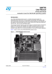
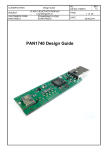
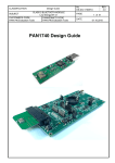
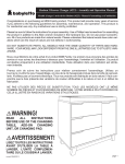
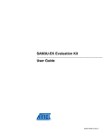
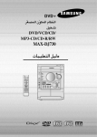
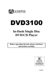
UM10895 QN9020 Mini DK user guide Rev. 1 — 1 June 2015 User manual Document information Info Content Keywords Mini DK, JLink OB, UART, SWD, GPIO, LED, button, power supply, buzzer Abstract This user manual describes the features of the QN9020_MINIDK_V5 board. UM10895 NXP Semiconductors QN9020 Mini DK user guide Revision history Rev Date Description v.1 20150601 Initial release Contact information For more information, please visit: http://www.nxp.com For sales office addresses, please send an email to: [email protected] UM10895 User manual All information provided in this document is subject to legal disclaimers. Rev. 1 — 1 June 2015 © NXP Semiconductors N.V. 2015. All rights reserved. 2 of 18 UM10895 NXP Semiconductors QN9020 Mini DK user guide 1. Introduction This user manual describes the hardware details of the QN9020 Mini Development Kit (Mini DK). The “QN9020_MINIDK_V5” board is discussed in detail. 1.1 Kit contents The QN9020 mini development kit includes the following: • QN9020 mini development board • QN9020 USB dongle • USB cable 1.2 Additional resource For additional resources, visit http://www.nxp.com/products/microcontrollers/key_feature/bluetooth. 2. Hardware description The QN9020 mini development board provides easy access to peripherals such as buttons, Piezo buzzer and LED. The board also provides useful interfaces such as a USB port for UART communication and JLink debug, and a GPIO/optional sensor board connector. A USB Dongle is a Bluetooth device powered by the QN9020. It acts as a master when communicating with the QN9020. 2.1 Hardware overview The hardware blocks in the QN9020 Mini DK, and the functional relationship of each main component, are shown in Figure 1. GPIO/SENSOR CONNECTOR GPIO/SENSOR CONNECTOR UART Virtual UART USB PORT RESET JLink OB (ATSAM3U2C) SWD QN9020 RF MATCHING OnBoard ANTENNA LED1 POWER LED2 CR2032 BUTTON1 BUTTON2 GPIO/SENSOR CONNECTOR aaa-018330 Fig 1. UM10895 User manual The QN9020 functional diagram All information provided in this document is subject to legal disclaimers. Rev. 1 — 1 June 2015 © NXP Semiconductors N.V. 2015. All rights reserved. 3 of 18 UM10895 NXP Semiconductors QN9020 Mini DK user guide The component layout on both the sides of the board is shown in Figure 2 and Figure 3. The detailed information of each component is listed in Table 1. UM10895 User manual Fig 2. The QN9020 board top view Fig 3. The QN9020 board bottom view All information provided in this document is subject to legal disclaimers. Rev. 1 — 1 June 2015 © NXP Semiconductors N.V. 2015. All rights reserved. 4 of 18 UM10895 NXP Semiconductors QN9020 Mini DK user guide Table 1. QN9020 board components list S.No Name Description 1 JLink OB ATSAM3U2C; used to offer SWD and UART interfaces for QN9020 debug and communication 2 connector optional; used for connecting sensor board 3 debug port debug port for ATSAM3U2CA 4 mini USB port power and communication port 5 power source select jumper used for power source selection; see Section 2.3 6 current measurement jumper used to measure the QN9020 device power consumption 7 LDO (TPS73630) 5 V to 3 V regulator 8 button1 used as input; see Section 2.9 9 button2 used as input; see Section 2.9 10 LED2 used as output; see Section 2.8 11 QN9020 GPIO Port used for interface extension 12 LED1 used as output; see Section 2.8 13 SWD resistors zero ohm resistors; shorted for QN9020 device debug 14 UART interface used as communication port for QN9020 device 15 PCB antenna on-board Bluetooth antenna 16 QN9020 chip QN9020 chip 17 QN9020 reset button used for QN9020 hardware reset 18 CR2032 battery holder CR2032 battery holder 19 Piezo buzzer buzzer: KLJ-1230 20 jumper used for power cycle ATSAM3U2CA 2.2 Default jumper settings on Mini DK board The jumpers on QN9020 Mini DK are factory set to power the board over the USB. The factory-set jumper and switch settings are shown in Table 2. Table 2. Jumper QN9020 Mini DK board components list Pins to be shorted using jumpers Function J11 2 and 3 USB powered J12 1 and 2 VCC_QN9020 3.3 V J13 1 and 2 VCC_MB 3.3 V 2.3 Power supply The QN9020 board has two power supply modes: 1. Bus-power mode: The board can be powered using the USB cable. The onboard LDO is used to regulate output voltage to 3 V and supplies power to all parts on the board. UM10895 User manual All information provided in this document is subject to legal disclaimers. Rev. 1 — 1 June 2015 © NXP Semiconductors N.V. 2015. All rights reserved. 5 of 18 UM10895 NXP Semiconductors QN9020 Mini DK user guide 2. Battery-power mode: The CR2032 supplies power to QN9020 and optional sensor connector when it is in battery-power mode. The JLink OB still uses the LDO as power supply via USB cable. When using USB interface as a power supply, connect the jumper J11 pin 2 and pin 3; see Figure 4. Fig 4. Connecting jumper J11 Pin 2 and Pin 3 to select USB as power supply When using a CR2032 coin cell as a power supply, connect the jumper J11 pin 1 and pin 2; see Figure 5. Fig 5. UM10895 User manual Connecting jumper J11 Pin1 and Pin 2 to select CR2032 coil cell as power supply All information provided in this document is subject to legal disclaimers. Rev. 1 — 1 June 2015 © NXP Semiconductors N.V. 2015. All rights reserved. 6 of 18 UM10895 NXP Semiconductors QN9020 Mini DK user guide 2.4 Segger JLink OB part The Segger Jlink OB offers the SWD and UART interface. Users can download or update firmware into a QN9020 device by using the UART or SWD interface. Furthermore, it is convenient to debug the program for a QN9020 device using SWD interface. To program or debug the QN9020 device using the Segger JLink OB, the 0 resistors R37, R38 should be soldered; see Figure 6. Fig 6. Connect R37, R38 In order to use a USB to UART bridge for the QN9020 download, the solder bridge SB3, SB4 should be shorted; see Figure 7. Fig 7. UM10895 User manual Short R35, R36 All information provided in this document is subject to legal disclaimers. Rev. 1 — 1 June 2015 © NXP Semiconductors N.V. 2015. All rights reserved. 7 of 18 UM10895 NXP Semiconductors QN9020 Mini DK user guide 2.5 QN9020 Device The QN9020 device is integrated with a BLE radio, controller, protocol stack and profile software, and a high performance MCU on a single chip; see Figure 8. Fig 8. The QN9020 device 2.6 GPIO Interface The connectors J6, J7, J8 and J9 provide GPIO connection. The net name is shown in Figure 9. J9 P3.0_ADCP3.2_SPI0-MISO P3.4_SPI0-CLK P3.6 GND 1 3 5 7 9 J8 2 4 6 8 10 nRESET P3.1_ADC+ P2.1_UART1-TX P2.3_I2C-SDA P3.3_SPI0-MOSI P2.5 P3.5_SPI0-CS P2.7_PWM QN_VCC_3.3 V QN_VCC_3.3 V P0.0 UART0-TX P1.1_SPI1-MOSI J6 P0.1_UART0-CTS P0.3 P0.5 SWCLK/TCK GND Fig 9. UM10895 User manual 1 3 5 7 9 1 2 3 4 5 6 7 8 9 10 P2.0_UART1-RX P2.2 P2.4_I2C-SCL P2.6_PWM GND J7 2 4 6 8 10 P0.2 UART0-RTS P1.3_SPI1-CLK P0.4 SWDIO/TMS QN_VCC_3.3 V P1.5_PWM P1.7_UART0-RX QN_VCC_3.3 V 1 2 3 4 5 6 7 8 9 10 P1.0_SPI1-MISO P1.2_SPI1-CS P1.4 P1.6_PWM GND aaa-018338 QN9020 GPIO connections All information provided in this document is subject to legal disclaimers. Rev. 1 — 1 June 2015 © NXP Semiconductors N.V. 2015. All rights reserved. 8 of 18 UM10895 NXP Semiconductors QN9020 Mini DK user guide 2.7 QN9020 Reset button The reset button is used to provide hardware reset to the QN9020 device. When programming the QN9020 using UART interface of Segger JLink OB, the reset button should be pressed first to ensure that QN9020 is in boot mode. See Figure 10 for the detailed circuit. SW3 reset button 1 nRESET 2 aaa-018339 Fig 10. QN9020 reset 2.8 LED The QN9020 board offers two programmable LEDs, which are connected to the QN9020 device GPIO. LED1 and LED2 are connected to GPIO P0.5 and P0.6 respectively. The connections are shown in Figure 11. The LEDs are powered-up when the corresponding GPIO outputs switch to logic low level. QN_VIO LED1 P0.5 D2 R20 470 Ω LED2 P0.4 D3 R21 470 Ω aaa-018340 Fig 11. LED circuit 2.9 Button The QN9020 board offers two buttons which are connected to QN9020 device GPIO. Button 1 and button 2 are connected to GPIO P1.4 and P1.5 respectively. See Figure 12 for detailed circuits. When using the buttons, the GPIO P1.4 and P1.5 must be configured as inputs. Logic low input is applied to QN9020 when a button is pressed. QN_VIO button 1 1 4 2 SW1 R15 P1.4 3 100 kΩ button 2 1 4 2 SW2 3 R18 P1.5 100 kΩ aaa-018341 Fig 12. Button circuit UM10895 User manual All information provided in this document is subject to legal disclaimers. Rev. 1 — 1 June 2015 © NXP Semiconductors N.V. 2015. All rights reserved. 9 of 18 UM10895 NXP Semiconductors QN9020 Mini DK user guide 2.10 Piezo buzzer The Piezo buzzer receives input from GPIO P2.6; see Figure 13. Refer to KLJ-1230 data sheet for detailed information. B1 1 2 buzzer P2.6_PWM aaa-018342 Fig 13. Piezo buzzer circuit 2.11 Optional sensor connector These connectors are used as an interface to connect the sensor board. The pin name definitions are shown in Figure 14. J5 QN_VIO QN_VIO QN_VIO J10 1 1 P3.0_ADC- 2 2 P3.1_ADC+ 3 3 P3.6 4 4 P2.3_I2C-SDA 5 5 P2.4_I2C-SCL 6 6 7 7 8 8 9 9 10 10 11 11 P3.5_SPIO-CS 12 12 GND R16 0Ω R17 R22 0Ω 0Ω P0.3 P0.4 P0.5 P3.3_SPIO-MOSI aaa-018343 Fig 14. Connecting the sensor board 2.12 Current measurement The jumper J12 is used to measure the QN9020 device current. In current test mode, the digital ammeter should be connected in series with J12. In the other modes, pin 1 and pin 2 of J12 are shorted. A jumper cap is used to short the pins. UM10895 User manual All information provided in this document is subject to legal disclaimers. Rev. 1 — 1 June 2015 © NXP Semiconductors N.V. 2015. All rights reserved. 10 of 18 UM10895 NXP Semiconductors QN9020 Mini DK user guide 3. Appendix - Schematics and PCB layout DHSDP DHSDM MB_VCC_3.3V DFSDM DFSDP LED_RED2 VCORE LED_RED1 VCORE ENSPI MB_VCC_3.3V 3.1 Schematics C22 DHSDP DHSDM VBG VDDUTMI DFSDP DFSDM GNDUTMI PA28 VDDCORE PA31 PA29 VDDIO4 GND4 PB0 PB1 PB2 PB11 PB12 PB13 PA27 PB5 PB6 VDDCORE4 R12 6.8 kΩ 10 pF XIN32 XOUT32 JTAGSEL NRSTB GNDBU TST VDDBU ERASE PA12 FWVP PA10 PA11 PA9 PA8 VDDIO2 GND2 XIN XIN XOUT XOUT VDDPLL VCORE GNDPLL PB9 C20 0.1 μF PB10 PB14 PB17 PB18 PB19 PB20 PB21 PB22 PB23 GND3 VDDIO3 VDDCORE3 PB24 NRST TCK VCORE PI_RST PI_TCK TMS PI_TMS TDO VDDIN PI_TDO VDDOUT TDI MB_VCC_3.3V MB_VCC_3.3V VCORE PI_TDI C17 10 μF C18 10 μF C19 0.1 μF MB_VCC_3.3V TX0 MB_VCC_3.3V RX0 RTS CTS C16 MB_VCC_3.3V VDDCORE2 SB6 TRSTin SB5 TXData TCKout VCORE MB_VCC_3.3V PA7 ENSPI PA6 TDOin RXData TDIout PA5 TMSout PA4 TCKout TRESin TMSin TRESout TDlin PA2 PA3 VCORE TRSTout TCKin RTCKin C21 100 99 98 97 96 95 94 93 92 91 90 89 88 87 86 85 84 83 82 81 80 79 78 77 76 VDDANA 1 75 ADVREF 2 74 GNDANA 73 3 AD12BVREF 4 72 PA22 5 71 PA30 6 70 PB3 7 69 PB4 68 8 VDDCORE1 9 67 PA13 10 66 PA14 11 65 PA15 12 64 PA16 13 63 ATSAM3U2CA PA17 14 62 PB16 15 61 PB15 16 60 PA18 17 59 PA19 18 58 PA20 19 57 PA21 20 56 PA23 21 55 VDDIO1 54 22 PA24 23 53 PA25 24 52 PA26 51 25 26 27 28 29 30 31 32 33 34 35 36 37 38 39 40 41 42 43 44 45 46 47 48 49 50 PA0 PA1 MB_VCC_3.3V PB7 U1 PB8 0.1 μF 10 nF R19 TP1 1 kΩ aaa-018546 Fig 15. JLink MPU UM10895 User manual All information provided in this document is subject to legal disclaimers. Rev. 1 — 1 June 2015 © NXP Semiconductors N.V. 2015. All rights reserved. 11 of 18 UM10895 NXP Semiconductors QN9020 Mini DK user guide JTAG interface to QN9020 LED_RED1 D1 R13 LED4 R6 MB_VCC_3.3V LED_RED2 D1 0Ω R14 LED4 T_TRST TRSTout 220 Ω TRSTin MB_VCC_3.3V R9 220 Ω T_TDI TDIout XOUT 0Ω C2 18 pF 3 TDIin 2 C3 18 pF XIN J2 R7 4 jump 150 Ω TMSin 1 SWCLK/TCK T_TCK TCKout jump 150 Ω TCKin SWCLK/TCK T_RTCK RTCKin T_TDO TDOin ATSAM3U2CA programming interface SWDIO/TMS J3 R8 MB_VCC_3.3V SWDIO/TMS T_TMS TMSout Y1 12 MΩ R10 TRESout T_RESET 0Ω R11 nRESET 0Ω TRESin R5 4.7 kΩ R29 DFSON J1 S4 9 6 1 2 3 4 5 S3 R3 4.7 kΩ R4 4.7 kΩ J4 MB_VCC_3.3V PI_TMS R28 S1 DFSOP GND 39 Ω 1% V PI_TCK D- VS DHSON D+ 1 10 2 9 3 CON10C 8 4 7 5 6 UART interface to QN9020 PI_RST VCC R30 1 MΩ P0.2_UART0-RTS solder_bridge SB2 RTS P0.1_UART0-CTS solder_bridge PI_TDO SB3 RXD P0.0_UART0-TX solder_bridge U5 IO2 G SB1 CTS R26 0Ω PI_TDI DHSOP ID S2 8 7 miniusb_typeB R2 4.7 kΩ 39 Ω 1% VBUS 3 2 4 1 IO1 SB4 TXD GND P1.7_UART0-RX solder_bridge PRTR5VOU2X C36 C24 1 nF 0.1 μF MB_VCC_3.3V VCORE MB_VCC_3.3V MB_VCC_3.3V C23 C5 0.1 μF 10 μF C7 0.1 μF C6 0.1 μF C9 0.1 μF C8 0.1 μF C11 0.1 μF C13 0.1 μF C10 0.1 μF C12 0.1 μF GND C15 0.1 μF C14 0.1 μF GND VS VS VBUS VBUS aaa-018344 Fig 16. JLink power supply and others U2 V5 VIN VBUS R25 0Ω GND EN TP2 1 2 3 5 J13 VOUT MB_VCC_3.3V TPS73633 4 NR/FB C26 C29 0.1 μF C30 10 μF 16 V JUMP2 10 nF GND GND BAT1 1 J11 R24 3 2 0Ω 1 2 QN_VIO J12 QN_VCC_3.3V JUMP3 JUMP2 3 QN current test battery Note: connect jumper J11 PIN2, 3 LDO as a power supply connect jumper J11 PIN1, 2 battery as a power supply aaa-018345 Fig 17. Power supply UM10895 User manual All information provided in this document is subject to legal disclaimers. Rev. 1 — 1 June 2015 © NXP Semiconductors N.V. 2015. All rights reserved. 12 of 18 UM10895 NXP Semiconductors QN9020 Mini DK user guide QN_VCC_3.3 V QN9020 device Y3 16 M P3.5_SPIOCS P3.4_SPIOCLK REXT VDD3 XTAL2 XTAL1 P3.0_ADC- P3.3_SPIOMOSI P3_4 P3_5 P3.2_SPIOMISO P3_3 P3_2 P3_1 P3_0 9 28 10 27 11 26 12 25 P1.7_UART0-RX C37 15 16 17 18 19 20 21 22 23 100 nF P0.5 SWCLK/TCK R32 GND 56 kΩ VSS2 100 nF L3 2.0 nH RFP L1 1.1 nH RFN C46 P1.3_SPI1-CLK L2 P1.5_PWM P1.7_UART0-RX RVDD QN_VCC_3.3 V P3_6 P2_0 P2_1 P2_2 P2_3 P2_4 2 3 4 5 6 7 8 9 10 P0.0 UART0-TX P0.2 UART0-RTS P0.4 SWDIO/TMS QN_VCC_3.3 V J7 P1.1_SPI1-MOSI 1.5 pF 6.2 nH RSTN 1 A1 antenna C44 nRESET nRESET P3.6 P2.0_UART1-RX C39 2.2 nF C42 8.2 pF R31 100 kΩ 2 3 4 5 6 7 8 9 10 P1.0_SPI1-MISO P1.2_SPI1-CS P1.4 P1.6_PWM GND J8 P2.1_UART1-TX P2.1_UART1-TX P2.3_I2C-SDA C41 1 μF P2.2 1 C47 1.0 pF P2.5 P2.7_PWM P2.3_I2C-SDA QN_VCC_3.3 V P2.4_I2C-SCL 1 2 3 4 5 6 7 8 9 10 P2.0_UART1-RX P2.2 P2.4_I2C-SCL P2.6_PWM GND 24 J9 P3.0_ADC- P2.5 P1_7 VDD1 14 GND GND VSS3 29 13 P0.3 P2_5 VSS1 30 8 P2_6 P0_0 P0.0_UART0-TX 7 QN9020 P2_7 P0_1 P0.1_UART0-CTS U6 31 P2.7_PWM P0.2_UART0-RTS 6 P1_0 P0_2 32 P1.0_SPI1-MISO P0_3 P0.3 C43 37 VDD2 36 5 P1_1 P0.4 38 33 P1.2_SPI1-CS P0_4 39 4 P1.1_SPI1-MOSI P0_5 P0.5 40 34 P1_2 22 pF XTAL1_32K 41 3 P1.3_SPI1-CLK C45 42 35 P1_3 Y2 32.768 kHz 43 J6 P0.1_UART0-CTS 2 P1.4 22 pF XTAL2_32K 44 P1_4 SWDIO/TMS 45 P1.5_PWM P0_6 46 P1_5 P0_7 47 P1.6_PWM 100 nF SWCLK/TCK 48 49 1 P1_6 VCC DCC GND L4 10 μH C38 P3.1_ADC+ L5 15 nH C40 QN9020 GPIO C48 1 μF P2.6_PWM QN_VCC_3.3 V P3.2_SPI0-MISO P3.4_SPI0-CLK P3.6 GND 1 2 3 4 5 6 7 8 9 10 nRESET P3.1_ADC+ P3.3_SPI0-MOSI P3.5_SPI0-CS QN_VCC_3.3 V 100 nF QN_VIO USER LED button 1 1 2 4 USER BUTTON SW1 2 4 RESET BUTTON SW2 SW3 reset button 1 QN_VIO 100 kΩ P1.5_PWM R18 3 QN_VIO QN_VIO R15 P1.4 3 button 2 1 BUZZER P0.5 LED1 D2 1 2 P2.6_PWM 470 Ω 100 kΩ P0.4 nRESET B1 R20 LED2 D3 R21 buzzer 470 Ω 2 QN_VIO CONNECTOR FOR SENSOR BOARD J10 J5 1 2 3 4 5 6 1 2 3 4 5 6 7 8 9 10 11 12 7 8 9 10 11 12 P3.0_ADCP3.1_ADC+ P3.6 P2.3_I2C-SDA P2.4_I2C-SCL R16 0Ω R22 0Ω R17 0Ω P0.3 P0.4 P0.5 P3.3_SPIO-MOSI P3.5_SPIO-CS GND aaa-018346 Fig 18. BLE - QN9020 UM10895 User manual All information provided in this document is subject to legal disclaimers. Rev. 1 — 1 June 2015 © NXP Semiconductors N.V. 2015. All rights reserved. 13 of 18 UM10895 NXP Semiconductors QN9020 Mini DK user guide 3.2 PCB Layout J10 J9 J6 GND P3.5 P3.3 R22 P0.5 R17 P0.4 R16 P0.3 SCL SDA P3.6 P3.1 P3.0 R2 R4 VCC VCC Y3 L3 C46 A1 C47 43 C L5 L4 C42 C41 C39 R31 L2 L1 U6 R26 C7 C12 R37 R10 R11 R38 R6 C40 Y2 C45 C38 C37 RXD TXD CTS RTS C48 R36 R35 TP1 R34 R33 SWDIO SWCLK LED1 R21 D3 LED2 P1.7-P1.0 P2.7-P2.0 BUTTON2 J8 R18 QN9020_MINIDK_V7 R150121 R20 D2 J7 SW2 R23 R27 C6 R9 R7 R8 BUTTON1 C11 C5 SW1 J13 power for U1 J12 power for U6 J11 power select R15 U1 SEGGER J-LinkTMTechnology www.segger,com 3 C23 R19 QN_RST C17 C18 C19 C13 C8 C20 C3 C16 C10 D1 R13 R28 R14 2 U2 C29 C30 J11 VCC J12 QNVCC R30 C36 1 TP2 C26 R25 C24 R24 Y1 C2 R29 J1 J13 R12 C21 C22 C14 C15 C9 SW3 R3 R5 J5 U5 VBAT P3.0-P3.6 R C 32 44 J4 P0.0-P0.7 aaa-018347 Fig 19. Silk screen top UM10895 User manual All information provided in this document is subject to legal disclaimers. Rev. 1 — 1 June 2015 © NXP Semiconductors N.V. 2015. All rights reserved. 14 of 18 UM10895 NXP Semiconductors QN9020 Mini DK user guide 0.0P 1.0P 2.0P 3.0P 4.0P 5.0P 6.0P 7.0P CCV DNG TESER 0.3P 1.3P 2.3P 3.3P 4.3P 5.3P 6.3P CCV DNG CCV DNG 7.1P 6.1P 5.1P 4.1P 3.1P 2.1P 1.1P 0.1P CCV DNG 7.2P 6.2P 5.2P 4.2P 3.2P 2.2P 1.2P 0.2P 1B SUBV -D +D DNG 3 2 1 tabV CCV 1TAB aaa-018348 Fig 20. Silk screen bottom 4. Abbreviations Table 3. UM10895 User manual Abbreviations Acronym Description UART Universal Asynchronous Receiver/Transmitter DK Development Kit LDO Low Dropout Output SWD Serial Wire Debug PCB Printed-Circuit Board BLE Bluetooth Low Energy MCU Micro-Controller Unit GPIO General Purpose Input/Output ISP In System Programming USB Universal Serial Bus All information provided in this document is subject to legal disclaimers. Rev. 1 — 1 June 2015 © NXP Semiconductors N.V. 2015. All rights reserved. 15 of 18 UM10895 NXP Semiconductors QN9020 Mini DK user guide 5. Legal information 5.1 Definitions Draft — The document is a draft version only. The content is still under internal review and subject to formal approval, which may result in modifications or additions. NXP Semiconductors does not give any representations or warranties as to the accuracy or completeness of information included herein and shall have no liability for the consequences of use of such information. 5.2 Disclaimers Limited warranty and liability — Information in this document is believed to be accurate and reliable. However, NXP Semiconductors does not give any representations or warranties, expressed or implied, as to the accuracy or completeness of such information and shall have no liability for the consequences of use of such information. NXP Semiconductors takes no responsibility for the content in this document if provided by an information source outside of NXP Semiconductors. In no event shall NXP Semiconductors be liable for any indirect, incidental, punitive, special or consequential damages (including - without limitation - lost profits, lost savings, business interruption, costs related to the removal or replacement of any products or rework charges) whether or not such damages are based on tort (including negligence), warranty, breach of contract or any other legal theory. Notwithstanding any damages that customer might incur for any reason whatsoever, NXP Semiconductors’ aggregate and cumulative liability towards customer for the products described herein shall be limited in accordance with the Terms and conditions of commercial sale of NXP Semiconductors. Right to make changes — NXP Semiconductors reserves the right to make changes to information published in this document, including without limitation specifications and product descriptions, at any time and without notice. This document supersedes and replaces all information supplied prior to the publication hereof. Suitability for use — NXP Semiconductors products are not designed, authorized or warranted to be suitable for use in life support, life-critical or safety-critical systems or equipment, nor in applications where failure or malfunction of an NXP Semiconductors product can reasonably be expected to result in personal injury, death or severe property or environmental damage. NXP Semiconductors and its suppliers accept no liability for inclusion and/or use of NXP Semiconductors products in such equipment or applications and therefore such inclusion and/or use is at the customer’s own risk. Applications — Applications that are described herein for any of these products are for illustrative purposes only. NXP Semiconductors makes no representation or warranty that such applications will be suitable for the specified use without further testing or modification. Customers are responsible for the design and operation of their applications and products using NXP Semiconductors products, and NXP Semiconductors accepts no liability for any assistance with applications or customer product UM10895 User manual design. It is customer’s sole responsibility to determine whether the NXP Semiconductors product is suitable and fit for the customer’s applications and products planned, as well as for the planned application and use of customer’s third party customer(s). Customers should provide appropriate design and operating safeguards to minimize the risks associated with their applications and products. NXP Semiconductors does not accept any liability related to any default, damage, costs or problem which is based on any weakness or default in the customer’s applications or products, or the application or use by customer’s third party customer(s). Customer is responsible for doing all necessary testing for the customer’s applications and products using NXP Semiconductors products in order to avoid a default of the applications and the products or of the application or use by customer’s third party customer(s). NXP does not accept any liability in this respect. Export control — This document as well as the item(s) described herein may be subject to export control regulations. Export might require a prior authorization from competent authorities. Evaluation products — This product is provided on an “as is” and “with all faults” basis for evaluation purposes only. NXP Semiconductors, its affiliates and their suppliers expressly disclaim all warranties, whether express, implied or statutory, including but not limited to the implied warranties of non-infringement, merchantability and fitness for a particular purpose. The entire risk as to the quality, or arising out of the use or performance, of this product remains with customer. In no event shall NXP Semiconductors, its affiliates or their suppliers be liable to customer for any special, indirect, consequential, punitive or incidental damages (including without limitation damages for loss of business, business interruption, loss of use, loss of data or information, and the like) arising out the use of or inability to use the product, whether or not based on tort (including negligence), strict liability, breach of contract, breach of warranty or any other theory, even if advised of the possibility of such damages. Notwithstanding any damages that customer might incur for any reason whatsoever (including without limitation, all damages referenced above and all direct or general damages), the entire liability of NXP Semiconductors, its affiliates and their suppliers and customer’s exclusive remedy for all of the foregoing shall be limited to actual damages incurred by customer based on reasonable reliance up to the greater of the amount actually paid by customer for the product or five dollars (US$5.00). The foregoing limitations, exclusions and disclaimers shall apply to the maximum extent permitted by applicable law, even if any remedy fails of its essential purpose. Translations — A non-English (translated) version of a document is for reference only. The English version shall prevail in case of any discrepancy between the translated and English versions. 5.3 Trademarks Notice: All referenced brands, product names, service names and trademarks are the property of their respective owners. All information provided in this document is subject to legal disclaimers. Rev. 1 — 1 June 2015 © NXP Semiconductors N.V. 2015. All rights reserved. 16 of 18 UM10895 NXP Semiconductors QN9020 Mini DK user guide 6. Tables Table 1. Table 2. QN9020 Mini DK board components list. . . . . . .5 QN9020 Mini DK board components list. . . . . . .5 Table 3. Abbreviations . . . . . . . . . . . . . . . . . . . . . . . . . 15 7. Figures Fig 1. Fig 2. Fig 3. Fig 4. Fig 5. Fig 6. Fig 7. Fig 8. Fig 9. Fig 10. Fig 11. Fig 12. Fig 13. Fig 14. Fig 15. Fig 16. Fig 17. Fig 18. Fig 19. Fig 20. Mini DK functional diagram . . . . . . . . . . . . . . . . . .3 Mini DK top view . . . . . . . . . . . . . . . . . . . . . . . . . .4 Mini DK board bottom view . . . . . . . . . . . . . . . . . .4 Connect jumper J11 Pin 2 and Pin 3 to select USB as power supply . . . . . . . . . . . . . . . . . . . . . . . . . . .6 Connect jumper J11 Pin1 and Pin 2 to select CR2032 coil cell as power supply . . . . . . . . . . . . .6 Connect the J2, J3 . . . . . . . . . . . . . . . . . . . . . . . . .7 Short the SB3,SB4. . . . . . . . . . . . . . . . . . . . . . . . .7 QN9020 Device . . . . . . . . . . . . . . . . . . . . . . . . . . .8 QN9020 GPIO Definition . . . . . . . . . . . . . . . . . . . .8 QN9020 Reset circuit. . . . . . . . . . . . . . . . . . . . . . .9 LED circuit . . . . . . . . . . . . . . . . . . . . . . . . . . . . . . .9 Button circuit . . . . . . . . . . . . . . . . . . . . . . . . . . . . .9 Piezo buzzer circuit . . . . . . . . . . . . . . . . . . . . . . .10 Connect for connecting sensor board . . . . . . . . .10 JLink MPU . . . . . . . . . . . . . . . . . . . . . . . . . . . . . . 11 JLink power supply and others . . . . . . . . . . . . . .12 Power supply . . . . . . . . . . . . . . . . . . . . . . . . . . . .12 BLE - QN9020 . . . . . . . . . . . . . . . . . . . . . . . . . . .13 Silk screen top . . . . . . . . . . . . . . . . . . . . . . . . . . .14 Silk screen bottom . . . . . . . . . . . . . . . . . . . . . . . .15 UM10895 User manual All information provided in this document is subject to legal disclaimers. Rev. 1 — 1 June 2015 © NXP Semiconductors N.V. 2015. All rights reserved. 17 of 18 UM10895 NXP Semiconductors QN9020 Mini DK user guide 8. Contents 1 1.1 1.2 2 2.1 2.2 2.3 2.4 2.5 2.6 2.7 2.8 2.9 2.10 2.11 2.12 3 3.1 3.2 4 5 5.1 5.2 5.3 6 7 8 Introduction . . . . . . . . . . . . . . . . . . . . . . . . . . . . 3 Kit contents . . . . . . . . . . . . . . . . . . . . . . . . . . . . 3 Additional resource . . . . . . . . . . . . . . . . . . . . . . 3 Hardware description . . . . . . . . . . . . . . . . . . . . 3 Hardware overview . . . . . . . . . . . . . . . . . . . . . . 3 Default jumper settings on Mini DK board . . . . 5 Power supply . . . . . . . . . . . . . . . . . . . . . . . . . . 5 Segger JLink OB part . . . . . . . . . . . . . . . . . . . . 7 QN9020 Device . . . . . . . . . . . . . . . . . . . . . . . . 8 GPIO Interface . . . . . . . . . . . . . . . . . . . . . . . . . 8 QN9020 Reset button . . . . . . . . . . . . . . . . . . . . 9 LED. . . . . . . . . . . . . . . . . . . . . . . . . . . . . . . . . . 9 Button . . . . . . . . . . . . . . . . . . . . . . . . . . . . . . . . 9 Piezo buzzer . . . . . . . . . . . . . . . . . . . . . . . . . . 10 Optional sensor connector . . . . . . . . . . . . . . . 10 Current measurement. . . . . . . . . . . . . . . . . . . 10 Appendix - Schematics and PCB layout . . . . 11 Schematics . . . . . . . . . . . . . . . . . . . . . . . . . . . 11 PCB Layout . . . . . . . . . . . . . . . . . . . . . . . . . . 14 Abbreviations . . . . . . . . . . . . . . . . . . . . . . . . . . 15 Legal information. . . . . . . . . . . . . . . . . . . . . . . 16 Definitions . . . . . . . . . . . . . . . . . . . . . . . . . . . . 16 Disclaimers . . . . . . . . . . . . . . . . . . . . . . . . . . . 16 Trademarks. . . . . . . . . . . . . . . . . . . . . . . . . . . 16 Tables . . . . . . . . . . . . . . . . . . . . . . . . . . . . . . . . 17 Figures . . . . . . . . . . . . . . . . . . . . . . . . . . . . . . . 17 Contents . . . . . . . . . . . . . . . . . . . . . . . . . . . . . . 18 Please be aware that important notices concerning this document and the product(s) described herein, have been included in section ‘Legal information’. © NXP Semiconductors N.V. 2015. All rights reserved. For more information, please visit: http://www.nxp.com For sales office addresses, please send an email to: [email protected] Date of release: 1 June 2015 Document identifier: UM10895