1
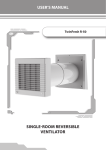
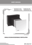
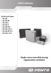
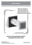
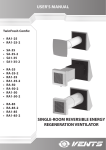
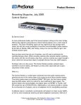
USER’S MANUAL
TwinFresh R1-50
SINGLE-ROOM REVERSIBLE
VENTILATOR
2
CONTENTS
Safety requirements
Introduction
Use
Delivery set
Designation key
Technical data
Design and operating logic
Mounting and set-up
Connection to power mains and control
Maintenance
Troubleshooting and fault handling
Transportation and storage rules
Manufacturer's warranty
Acceptance certificate
Seller information
Connection certificate
Warranty card
3
5
5
5
5
6
7
7
10
13
13
13
14
15
15
15
16
TwinFresh R1-50
3
SAFETY REQUIREMENTS
•
•
•
•
•
•
Read carefully the user’s manual prior to starting mounting and operation.
While mounting and operating the unit consider the requirements of the present user’s manual as well as requirements of all
applicable local and national building and electrical codes and standards.
Read carefully the warnings contained in the manual to make yourself aware of the safety rules!
Non-compliance with the rules and precautions stated in the user’s manual may result in a personal injury or the unit damage.
Read the manual carefully and keep it as long as you use the product.
In case of transferring operation of the unit to another person provide the user manual.
Symbol legend used in the manual:
WARNING!
DO NOT!
MOUNTING SAFETY PRECAUTIONS
Disconnect the unit from power supply before
mounting and repair operations.
Use the unit for the purpose intended only.
Do not operate the unit beyond the specified
temperature range. Do not operate the unit in
an aggressive and explosive medium.
Do not use damaged electric equipment
and conductors for electric connections.
Follow all applicable electrical safety rules while
operating and mounting the unit.
Unpack the unit carefully.
Unauthorized power cable length modification
is not allowed. Do not bend and do not damage
the power cable.
Keep heating and other devices away from
the unit power cable.
4
OPERATING SAFETY PRECAUTIONS
Do not touch the speed controller or the
control panel with wet hands!
No maintenance is allowed with wet hands.
Do not rinse the unit under water.
Protect the unit electric parts from water
ingress.
ON
Disconnect the unit from power supply
before maintenance.
Do not block the air duct when the unit is on.
OFF
Do not let children operate the unit.
Do not damage the power cable while
operating the unit. Do not put any objects
on the power cable.
Keep explosive and inflammable products
away of the unit.
Do not open the operating unit.
In case of unusual sounds, smoke disconnect
the unit from power supply and contact the
service centre.
Do not let air flow from the unit be directed
to the open flame devices or candles.
TwinFresh R1-50
5
INTRODUCTION
This user’s manual includes technical description, operation, installation and mounting guidelines, technical data for the singleroom reversible ventilator TwinFresh R1-50, hereinafter referred as the unit.
USE
The unit is designed to arrange permanent controllable air exchange in flats, cottages, hotels, cafes and other domestic and public
premises. The unit is equipped with a ceramic heat exchanger that enables supply of fresh air due to extract air heat energy utilization.
The unit heat exchange efficiency reaches 91%.
The unit is designed for through-the-wall mounting. The unit it suitable for installation in the walls from 250 mm up to 470 mm.
The unit is rated for continuous operation.
Transported medium must not contain any flammable or explosive mixtures, evaporation of chemicals, coarse dust, soot and oil
particles, sticky substances, fibrous materials, pathogens or any other harmful substances.
The unit is designed operation at the ambient temperature ranging from -20°C (-4 °F) up to +50°C (+122 °F).
DELIVERY SET
unit - 1 item;
Power cable, 3 m Unitronic LIYY UL CSA 5xAWG/7 (5x0.25) - 1 item;
User’s manual - 1 item;
Packing box - 1 item;
Fasteners - 1 item.
UNIT DESIGNATION KEY
TwinFresh R1-50
Air capacity [m3⁄ h]
Front panel type
RV TwinFresh-1 150.
Round connecting air duct
Unit name
TwinFresh - single-room reversible ventilator
6
TECHNICAL DATA
156 mm
274 mm
The main unit overall and connecting dimensions, outer view and technical parameters are shown in fig. 1 and in table 1.
470 mm
240 mm
156 mm
254 mm
240 мм
250 мм
Fig. 2. TwinFresh R-50 overall and connecting dimensions
Table 1. Technical data
Mode
1
2
Voltage [V]
230V/50 Hz
Power [W]
Air capacity [m3/h] (CFM)
RPM [min-1]
Noise level,
[dB(A)]
1,4
25
570
22
3,0
50
1100
29
IP
24
TwinFresh R1-50
7
DESIGN AND OPERATING LOGIC
Outer ventilation hood
Outer air duct
Inner air duct
Filter
Ceramic heat exchanger
Filter
Distance ring
Ventilation unit
Front panel
Fig. 2.Unit design
The unit consists of a plastic telescopic air duct, a ventilation unit with a decorative front panel and an outer ventilation hood, fig. 2.
The total telescopic air duct length is regulated due to position of the inner telescopic duct inside the outer telescopic duct.
Two filters and a ceramic heat exchanger are installed in the inner telescopic air duct. The filter is designed for supply air cleaning and
prevention of dust and foreign objects ingress inside the heat exchanger and the impeller. The heat exchanger is used to warm up supply
air flow by extract air heat energy and provide supply of warmed-up and filtered air to the room. The heat exchanger has a pull cord inside
to facilitate the unit maintenance.
The ventilation unit with a decorative front panel are to be installed on inner side. The outer ventilation hood is to be installed on the
outer building side to prevent ingress of water and large foreign objects into the unit.
MOUNTING AND SET-UP
The unit is designed for installation into a specially designed through hole inside a wall. The hole must be perpendicular to the wall
plane.
The mounting guidelines for the single-room reversible ventilator are shown in fig. 3, 4.
8
INSIDE
OUTSIDE
Ø160 + 10 mm
Fill the gaps with a mounting foam
Fig. 3. Unit mounting
Install the telescopic duct in the hole from outside and fill the gaps between the duct and the wall with a mounting foam. For easy
mounting keep the clearances between the duct and the wall within 5-10 mm. Fix the outer hood according to the wall holes with four
4x35 screws and the dowels 6x35 included into delivery set, fig. 4. Fix the ventilation unit to the wall with the screws 3x25 included into
delivery set and the dowels 5x25, fig. 4.
Hole spacing for fastening
of the ventilation unit
Hole spacing for the
outer hood fastening
150 mm
200 mm
75 mm
100 mm
98 mm
196 mm
Fig. 4. Hole spacing for the unit mounting
200 mm
100 mm
Ø 160 + 10 mm
4 holes
195 mm
97,5 mm
Ø 160 + 10 mm
4 holes
TwinFresh R1-50
9
The KVR-T control and the transformer unit (special accessory) is to be installed in a specially designed and prepared hole in a wall as
shown in fig. 5, in inaccessible for children places. While installation consider the length of the cable supplied with the unit.
A longer cable may be used on customer demand. The recommended cable type and marking are stated in the Delivery Set section.
KVR-T
А
70 mm
70 mm
R35 mm
48 mm
А
А-А
Fig. 5. Hole spacing for mounting of the control unit KVR-T (special accessory)
WARNING!
DO NOT INSTALL THE UNIT CLOSE TO CURTAINS, HANGINGS
AND OTHER OBJECTS THAT MAY BLOCK THE AIR DUCT AND
CAUSE DUST ACCUMULATION ON THE UNITS.
10
CONNECTION AND CONTROL
The unit is controlled with the external control and power unit KVR-T (special accessory), fig. 6.
The control and power KVR-T unit is used for operation mode selection and control. The unit is rated for connection to single-phase 230
V / 50 Hz. Separate power supply must be provided both to the control and power unit and to the ventilation unit.
Turning ON
2 speed mode
Extract/Supply mode*
Turning OFF
1 speed mode
Reversible operation mode
Fig. 6. KVR-T control and power unit.
Табл. 3Table 2. KVR-T data
Transformer data
Control and power
unit name
KVR-T-12
Power [W]
12
Voltage [V]
Note
Input
Output
230V/50 Hz
12
Connection
up to 4 units
The control unit is a three-key switch with an integrated printed circuit board for installation into a standard junction box. All electric
connection to the control unit and the ventilator are performed with the socket connectors for mounting and servicing facilitation. Each
mating part of the socket connector has a colour marking in compliance with marking on the circuit board to ensure correct and quick
electric installation.
The control unit is used to set one of four operation modes of the unit, fig. 6:
1. Ventilation mode (air extract / air supply)* at first speed with air flow 25 m3/h.
2. Ventilation mode (air extract / air supply)* at second speed with air flow 50 m3/h.
3. Reverse (heat recovery) operation at first speed with air flow 25 m3/h. The ventilator changes operation mode (air extract / air supply)
every 70 seconds.
4. Reverse (heat recovery) operation at second speed with air flow 50 m3/h. The ventilator changes operation mode (air extract / air
supply) every 70 seconds.
* - air flow direction depends on position of the jumper JMP1 on the circuit board. The jumper is set to provide supply mode by default,
fig. 6.
red
red
white
white
36
35
34
33
32
31
15
14
13
12
11
15
14
13
12
11
Marking "1-5" on the
connecting
cable socket connector
grey
brown
yellow
green
white
1
2
3
4
5
31 32
N
21
22
23
24
25
~230 V
L
1
2
3
4
5
11
12
13
14
15
ÕÒ3
1
2
3
4
5
36
35
34
33
40 39 38 37
JMP1
Marking "11-15" on the
controller socket
connector
Marking "21-25" on the
controller socket
connector
The unit is connected to the KVR-T controller with two cable channels. In ventilation mode all the connected units operate in air extract mode (the JMP1 jumper on the circuit board is in Flow out position) or in
supply mode (the JMP1 jumper on the circuit board is in Flow in position).
The electric connection is performed with a five-wire cable. The wires are marked in compliance with the delivered cable for easy installation. The minimum conductor cross section is 0.25 mm2. Power supply
230 V / 50 Hz must be provided both to the KVR-T control unit and to the ventilation unit (socket connectors 31-21 in each case).
Marking "1-5" on the
connecting
cable socket connector
white 5
green 4
yellow 3
brown 2
grey 1
Marking "11-15" on the
controller socket
connector
Twin Fresh R1-50
Fig. 7. Total wiring diagram for TwinFresh R1-50 connection to KVR-T controller
~230V
~230 V
Controller KVR-T
TwinFresh R1-50
11
red
white
green
yellow
brown
grey
white
green
yellow
brown
grey
grey
Channel A:1. TwinFresh R1-50
~230 V
Канал А:N. ТвинФреш Р1-50
~230 V
Channel B:N. TwinFresh R1-50
~230 V
~230 V
To connect up to 4 TwinFresh R1-50 units, follow the wiring diagram in fig. 8. Power supply 230 V / 50 Hz must be provided both to KVR (KVR-T) control unit and to each ventilation unit (socket connectors
31-32 for each case). The inputs at the controller socket connectors are marked 21 to 25.
The outputs at the controller socket connectors are marked 11 to 15.
The socket connectors on the delivered connecting cable delivered with the KVR-T unit are marked 1 to 5 and are designed for connection to the controller socket connectors , 11-15 for outputs and 21-25
for inputs.
Fig. 8. General wiring diagram for connection of up to 4 TwinFresh R1-50 units to KVR-T controller
T1 (12 W)
~230 В
red
yellow
yellow
white
brown
brown
grey
white
white
white
green
green
~230 V
KVR-T Controller
grey
grey
grey
grey
brown
brown
brown
brown
yellow
yellow
yellow
yellow
white
white
white
white
green
green
green
green
Channel B:1. TwinFresh R1-50
12
TwinFresh R1-50
13
MAINTENANCE
Disconnect the ventilator from power supply before any maintenance operation with the unit. Maintenance of the unit means regular
cleaning of the unit surfaces of dust and cleaning or replacement of the unit filters.
Removing of the heat exchanger and the filters: first take off the front panel, unscrew the fasteners, disconnect and remove the fan and
the distance ring. The heat exchanger is equipped with a special cord to facilitate its withdrawal together with the filters, fig. 9.
Remove dust with a soft brush, cloth or compressed air. Do not use water, abrasive detergents, solvents, sharp objects. The impeller
blades must be cleaned once in year.
Clean the filters as often as these gets soiled, but at least every 3 months.
To clean the filters flush those with water or use a vacuum cleaner. After cleaning install the dry filters inside the air duct.
The filter rated service life is 3 years. Contact the Seller for the new filters.
Cord
Heat exchanger
Filters
Fig. 9. Unit maintenance
TROUBLESHOOTING AND FAULT HANDLUNG
Table 3
Faults and fault handling
Problem
Possible reasons
No power supply
The unit does not start
The motor is jammed.
Low air flow
Noise, vibration
Fault handling
Make sure of correct power supply, otherwise
troubleshoot the connection error.
Turn the unit off. Troubleshoot the motor jam.
Restart the unit.
The filters are soiled.
Clean the filters.
The fan impeller is clogged.
Clean the fan impeller.
The screw tightening is loose.
Check and tighten the screws.
STORAGE AND TRANSPORTATION RULES
Store the unit in the manufacturer’s original packing box in a dry ventilated premise at the temperatures from +10°C up to + 40°C .
Storage environment must not contain aggressive vapours and chemical mixtures provoking corrosion, insulation and sealing
deformation.
Use hoist machinery for handling and storage operations to prevent the unit damage in consequence of falling or excessive oscillation.
Fulfil the handling requirements applicable for the applicable freight type.
Transportation with any vehicle type is allowed provided that the unit is protected against mechanical and weather damage.
Avoid any mechanical shocks and strokes during handling operations.
14
MANUFACTURER’S WARRANTY
The manufacturer sets forth the warranty period of the unit 24 months following the sale date via retail network, subject to the customer’s
ensuring compliance with the rules of transportation, storage, mounting and operation of the product.
In case of any unit malfunctions caused by a manufacturing defect within the warranty period the customer has a right for elimination
of unit defects by means of warranty servicing performed free of charge.
The warranty servicing implies performance of activities related to elimination of defects in the unit aimed to provide intended use of
the unit by the customer within the warranty period. The defects are eliminated either by replacing or repairing some unit components
or a unit assembly.
The warranty servicing does not include:
•
periodic unit maintenance;
•
mounting/dismantling
•
unit setup.
In case of warranty claim please submit the user manual with the sale date mark and an invoice to confirm the unit purchase.
The unit model shall comply with that one specified in the user manual.
For waranty service please contact your Seller.
Manufacturer’s warranty shall not apply in the following cases:
•
failure to submit the unit in complete set according to the package content stated in the user manual, including dismantling of the
unit components;
•
noncompliance of the unit model or marking to the data stated in the unit packaging and in the user manual;
•
non-timely technical maintenance of the unit;
•
visible damages of the unit casing and internal assemblies (external unit modifications required for the unit mounting are not
considered as damages);
•
altering the unit design or reworking of the unit;
•
replacing and using parts, units and components of the unit not prescribed by the manufacturing company;
•
misuse of the unit;
•
violation of the unit mounting rules by the user;
•
violation of the unit operation rules by the user;
•
connecting the unit to power mains other than stated in the user manual;
•
unit failure resulted from step voltage in power mains;
•
unauthorised repair of the unit;
•
repair of the unit by third persons unauthorised by the manufacturing company;
•
warranty period expiry;
•
violation of the unit transportation rules;
•
violation of the unit storage rules;
•
unlawful actions by third persons with respect to the unit;
•
unit failure resulted from force majeure (fire, flood, earthquake, war, hostilities of any kind, blockade);
•
absent seals, provided such seals are prescribed by the user manual;
•
failure to submit the user manual with the sale date marking;
•
failure to submit the invoice to confirm the unit purchase.
FOLLOW THE USER’S MANUAL REQUIREMENTS TO ENSURE NON-STOP AND TROUBLEFREE OPERATION OF THE UNIT.
WARRANTY CLAIMS FROM THE USER ARE ACCEPTED IN CASE OF SUBMITTING THE
UNIT, THE RELATED INVOICE AND THE USER’S MANUAL WITH THE SALE DATE MARKING.
TwinFresh R1-50
15
ACCEPTANCE CERTIFICATE
Product type
Single-room reversible ventilator
Model
TwinFresh R1-50
Serial number
Production date
is recognized as serviceable.
Stamp of the
acceptance inspector
SELLER INFORMATION
Shop name
Address
Telephone
E-mail
Sale date
The unit was received in complete set with the user's manual, the warranty conditions are clear and
understood.
Seller stamp here
Customer signature
MOUNTING CERTIFICATE
This is to certify that the air handling unit TwinFresh R1-50 has been connected to power mains pursuant
to the requirements stated in this user’s operation manual.
Company name
Address
Telephone
Installer name
Mounting date:
Signature:
Installer stamp here
The unit mounting meets all applicable local and national construction, electric and technical norms
and standards. I have no claims to the unit operation.
Signature:
16
WARRANTY CARD
Product type
Model
Single-room reversible ventilator
TwinFresh R1-50
Serial number
Production date
Sale date
Warranty period
Selling Company
Seller Stamp here
______________________________________________________________________________________________________
______________________________________________________________________________________________________
______________________________________________________________________________________________________
______________________________________________________________________________________________________
______________________________________________________________________________________________________
______________________________________________________________________________________________________
______________________________________________________________________________________________________
_________________________________________________________________________________________________
NOTES
____________________________________________________________________________________
____________________________________________________________________________________
____________________________________________________________________________________
____________________________________________________________________________________
____________________________________________________________________________________
____________________________________________________________________________________
____________________________________________________________________________________
____________________________________________________________________________________
____________________________________________________________________________________
____________________________________________________________________________________
____________________________________________________________________________________
____________________________________________________________________________________
____________________________________________________________________________________
____________________________________________________________________________________
____________________________________________________________________________________
____________________________________________________________________________________
____________________________________________________________________________________
____________________________________________________________________________________
____________________________________________________________________________________
____________________________________________________________________________________
____________________________________________________________________________________
____________________________________________________________________________________
____________________________________________________________________________________
V62-1(R1-50)EN-05(ng)
2013