1
SENTRIX
User Manual
v3.02
User Manual
9 October 2015
SENTRIX
User Manual
Content
1.
Introduction to SENTRIX ..........................................................................................1
1.1. Features .......................................................................................................2
1.2. Installation ...................................................................................................2
1.3. License information ...................................................................................2
2.
Using the model .......................................................................................................3
2.1. Buck converter example ...........................................................................3
2.2. Block masks ................................................................................................4
2.3. Block ports ..................................................................................................6
2.4. Netlist conventions ....................................................................................7
3.
Error messages .........................................................................................................9
3.1. Error categories..........................................................................................9
3.2. State dependence .....................................................................................9
www.zeonpowertec.com
SENTRIX
User Manual
Copyright ©2014-2015 ZeoN PowerTec.
IN NO EVENT SHALL ZEON POWERTEC BE LIABLE TO ANY PARTY FOR DIRECT, INDIRECT, SPECIAL,
INCIDENTAL, OR CONSEQUENTIAL DAMAGES, INCLUDING LOST PROFITS, ARISING OUT OF THE USE
OF THIS DOCUMENTATION, SOFTWARE OR HARDWARE, EVEN IF ZEON POWERTEC HAS BEEN
ADVISED OF THE POSSIBILITY OF SUCH DAMAGE.
ZEON POWERTEC SPECIFICALLY DISCLAIMS ANY WARRANTIES, INCLUDING, BUT NOT LIMITED TO,
THE IMPLIED WARRANTIES OF MERCHANTABILITY AND FITNESS FOR A PARTICULAR PURPOSE. THE
DOCUMENTATION, SOFTWARE OR HARDWARE IS PROVIDED "AS IS". ZEON POWERTEC HAS NO
OBLIGATION TO PROVIDE MAINTENANCE, SUPPORT, UPDATES, ENHANCEMENTS, OR
SENTRIX
User Manual
1.
Introduction to SENTRIX
In Simulink, control and other algorithm development for power converters requires
some kind of representation (model) for the converter.
A first approach is to define a behavioural model that more or less mimics the actual
electrical behaviour of the converter. Such a behavioural model generally allows fast
simulation. However, the development process can be tedious and the model,
although fast, is limited in accuracy. In another approach an electrical network of the
power converter is translated into an abstract mathematical model. All electrical
components, including parasites, can be taken into account. These models are rather
difficult to create for each individual power converter. In general the electrical network
models are far more accurate than the behavioural models but slow down the
simulation speed tremendously. Modelling becomes even more cumbersome when
the electrical network contains diodes. The state of a diode, conducting or nonconducting, and the precise moment of switching is not predictable a priori since the
state depends on the internal network instantaneous currents and voltages.
Furthermore electrical engineers prefer an electrical network representation instead of
a behavioural block diagram or abstract mathematical equations.
SENTRIX® is a level-2 MATLAB S-function that overcomes these hurdles. The applied
algorithm interprets a text file containing an electrical netlist representing the power
converter to be simulated. The represented power converter gets integrated into the
Simulink model seamlessly. Accurate switching of diodes is handled efficiently without
undesired loss of simulation speed.
SENTRIX® is available at www.zeonpowertec.com
1 - 11
SENTRIX
User Manual
1.1. Features
•
seamless integration into Simulink1 and flawless operation in conjunction with
the many available library components and toolboxes
•
MAC-OS and Windows operating systems2 are supported
•
ease of installation with small software footprint
•
basic electrical components - ideal inductors, ideal capacitors and resistors are included and support initial condition setting where relevant
•
ideal switches and diodes incorporate very fast transient calculation
•
ideal transformers with adjustable transfer ratio can be applied
•
meters support the measurement of any current or voltage inside the
electrical network
•
a simple ASCII netlist representation allows editing with any preferred
commercially available editor
•
multiple electrical networks can be instantiated in a single Simulink model
1.2. Installation
Extract the sentrix.zip file into a directory/folder of preference. Add the new directory/
folder to the MATLAB path or execute the simulation directly from the chosen
directory/folder3.
1.3. License information
A demo and a full version are available. The demo version is restricted in the number
of nodes (5) and components (7) in the electrical network. Current sources cannot be
applied in this version. The demo version is valid for a period of at maximum 190 days.
The full version has no restrictions and has a validity of one year.
Entering 'sentrix' at the MATLAB command prompt reports the current status of the
license.
1
For MATLAB R2011a (version 7.12) and later versions
2
Linux is not formally supported
3
The sentrix.p file must be 'visible' for Simulink by being in the work directory/folder or search path
2 - 11
SENTRIX
User Manual
2.
Using the model
A Simulink model can contain multiple instantiations of various SENTRIX electrical
networks. All these networks call the 'sentrix.p' level-2 MATLAB S-function. The
respective netlists per block are imported in the simulator and used by the Simulink
solver. The following example will demonstrate the usage.
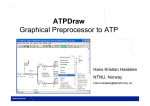
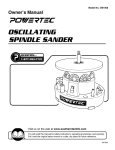
2.1. Buck converter example
Fig. 1 shows a Simulink model containing a SENTRIX electrical network representation
of a synchronous buck converter and its corresponding netlist.
Fig. 1
Simulink model containing a SENTRIX electrical network representation of a
buck converter with corresponding netlist
3 - 11
SENTRIX
User Manual
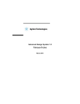
2.2. Block masks
The actual electrical network is masked for convenience. Fig. 2 shows the top level
mask. The 'Open file…' button will pop-up a window for selection of the relevant
netlist file. The extension of the netlist file has to be '.stx'. Alternatively a string
containing the file name including absolute or relative path can be edited directly in
the upper edit box. The lower edit box contains a vector with the initial condition
settings for all capacitor voltages and inductor currents in the network. The order of
appearance is the following: first all capacitor voltages and then all inductor currents in
numerical ascending order (e.g. VC1, VC2, VC3, IL1, IL2, …).
Fig. 2
Mask of the SENTRIX block
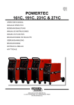
Underneath this top level mask the actual SENTRIX Electrical Network resides. This
next level including mask is shown in Fig. 3. The top level mask entries for the netlist
and initial conditions are automatically copied into the lower level mask.
As mentioned, the top level mask is for convenience only and might be deleted such
that the lower level SENTRIX Electrical Network mask becomes available at top level.
4 - 11
SENTRIX
User Manual
Fig. 3 SENTRIX Electric Network including mask
The SENTRIX Electrical Network calls the actual level-2 MATLAB S-function 'sentrix.p'
during execution using the desired netlist ('Netlist') and initial conditions ('InitCond').
A HitCross4 block must be connected between output ZX and input T. In this HitCross
block detection should be in either direction, offset equals zero and the output port
must be shown.
4
HitCross is a standard part of the Simulink library
5 - 11
SENTRIX
User Manual
2.3. Block ports
Tab. 1 gives an overview of the available model ports of the SENTRIX Electrical
Network. Each port is a multi-dimensional vector, depending on the amount of
components per type. Any suitable source from the Simulink library can be connected
to the input sources port. The output meters port can be connected to any suitable
sink from the Simulink library.
Tab. 1 SENTRIX Electrical Network ports
Port
Description
Remark
V/I
input sources
voltage before current sources in ascending order
(e.g. V1, V2, V3, I1, I2, …)
S
switches
ascending order (e.g. S1, S2, …), leave open when
no switches are present in the electrical network
A/U
output meters
current before voltage meters in ascending order
(e.g. A1, A2, A3, U1, U2, …)
ZX
zero-crossing detector
connect to the input of a standard Simulink
HitCross block - this block is always required to be
present with detection in either direction, offset
zero and output port shown
T
trigger input
connect to the input of a standard Simulink
HitCross block - this block is always required to be
present with detection in either direction, offset
zero and output port shown
6 - 11
SENTRIX
User Manual
2.4. Netlist conventions
The netlist describing the electrical network has to comply with several format rules.
An example netlist is shown in Fig. 4.
Netlist format rules:
•
the netlist is a standard text file in ASCII format
•
the netlist file extension is '.stx'
•
the first line is a compulsory header line containing arbitrary information
•
subsequent lines describe the electrical network, one line per component
•
a line has the format: 'component type', 'positive node', 'negative node'
'component value' - Tab. 2 gives an overview of the various components
•
on each line the type, nodes and value are separated by a space or a tab
•
the node numbers need to be positive integers
•
all components require values - see Tab. 2
•
'NaN' and 'Inf' are not allowed as component value
•
the components can be in arbitrary order
•
at least one capacitor or inductor should be included in the netlist
•
at least one source, either current or voltage, should be included in the netlist
•
at least one meter, either current or voltage, should be included in the netlist
Fig. 4 Example SENTRIX netlist
7 - 11
SENTRIX
User Manual
Tab. 2 Netlist components
Comp. Description
type
Positive
node
Negative
node
Comp.
value
A
current meter
current in
current
out
0
C
ideal capacitor
positive
terminal
negative
terminal
capacitor
value
D
ideal diode
anode
cathode
0
F
ideal transformer
primary
positive
terminal
negative
terminal
transfer
ratio primary/
secondary
turns
a Fx value (Nprim/Nsec) has
to be equal to the
corresponding Gx value,
so F1=G1, F2=G2, …
value
G
ideal transformer
secondary
positive
terminal
negative
terminal
transfer
ratio primary/
secondary
turns
a Gx value (Nprim/Nsec) has
to be equal to the
corresponding Fx value,
so G1=F1, G2=F2, …
value
I
current source
current in
current
out
0
actual value set in
Simulink top level model
via the first input port
S
ideal switch
current in
current
out
0
control of the switch is via
boolean logic ('0' = open,
'1' = short) and set in the
Simulink top level model
via the second input port
L
ideal inductor
current in
current
out
inductor
value
initial condition set via
mask
U
voltage meter
positive
terminal
negative
termal
0
V
voltage source
positive
terminal
negative
termal
0
8 - 11
Remark
initial condition set via
mask
actual value set in
Simulink top level model
via the first input port
SENTRIX
User Manual
3.
Error messages
SENTRIX incorporates a limited amount of error checking. Tab. 3 gives an overview of
the error messages and the probable causes. These error checks exist next to the
common Simulink error checks and can be traced back in the Simulink Diagnostic
Viewer.
3.1. Error categories
The various error messages are categorised into license, netlist, simulation and demo
version related. The demo version errors do not apply to the full version. License
information when a license error occurs can be retrieved by entering 'sentrix' at the
command prompt. The actual license information will be displayed. Netlist errors
prevent the simulation from starting execution, whereas simulation related errors can
occur during the simulation.
3.2. State dependence
SENTRIX applies ideal components for switches and diodes. Depending on the netlist
and network configuration this can result in a dependence between capacitor voltages
or inductor currents and sources or between sources directly. Examples are:
•
shorted capacitors
•
shorted voltage sources
•
open inductors
•
open current sources
•
capacitors in parallel to voltage sources
•
inductors in series with current sources
•
parallel voltage sources
•
series current sources
These cases are illegal since in the ideal case they would result in infinite currents or
voltages. The SENTRIX algorithm however will immediately try to change to a more
appropriate topology by turning on/off diodes present in the network and ensure that
the Simulink solver can continue the simulation without issuing an error.
In a practical non-ideal case these state dependences would never actually occur since
there is always (parasitic) impedance involved that limits the currents and voltages. So
as a solution when SENTRIX issues error E201 (see Tab. 3) the netlist can be changed
by adding resistance(s) to the network such that the state dependence is removed.
9 - 11
SENTRIX
User Manual
Tab. 3 Error messages
Code
Description
Cause
E000
No valid SENTRIX license for this
computer
A license is coupled to MAC-addresses.
The MAC-address of the current
computer is not in the license list.
E001
License expired - visit
The license has expired and has to be
www.zeonpowertec.com for license renewed
renewal
License related
Netlist related
E100
Netlist file does not exist
Either the path (absolute or relative) or
file name doesn’t exist
E101
Netlist file requires ''.stx'' extension
The file doesn’t have the required '.stx'
extension
E102
Unidentified component in netlist
A component other than defined in
Tab. 2 has been used
E103
At least one capacitor or inductor
has to be present in the network
Neither a single capacitor or inductor
has been used in the network
E104
At least one source has to be
present in the network
No source has been used in the
network
E105
At least one meter has to be
present in the network
No meter has been used in the network
E106
Double component entries in
netlist
The same component is used multiple
times
E107
Component values should not be
'Inf' or 'NaN'
Only numerical component values are
allowed
E108
Only positive integers allowed for
node numbering
A negative or non-integer node
reference is made in the netlist
E109
Wrong transformer dimensioning
Corresponding transformer transfer
ratios do not match
E110
Node error in netlist
A node number has been skipped from
the netlist
10 - 11
SENTRIX
User Manual
Code
Description
Cause
Simulation related
E200
Wrong number of initial conditions
set
The number of initial conditions set
does not match the actual number of
capacitors and inductors in the netlist
E201
State dependence
See section 3.2
E202
No solution found
During simulation the solver
encounters an unsolvable network
configuration
E203
Conflicting initial conditions
The initial conditions are chosen such
that the solver finds no suitable
network configuration
Demo version related
E300
Maximum number of demo version Too many nodes or components are
nodes (5) or components (7)
used
reached
E301
No current source allowed in the
demo version
11 - 11
Current sources are not to be used
SENTRIX
User Manual
www.zeonpowertec.com
Copyright ©2014-2015 ZeoN PowerTec.
IN NO EVENT SHALL ZEON POWERTEC BE LIABLE TO ANY PARTY FOR DIRECT, INDIRECT, SPECIAL,
INCIDENTAL, OR CONSEQUENTIAL DAMAGES, INCLUDING LOST PROFITS, ARISING OUT OF THE USE
OF THIS DOCUMENTATION, SOFTWARE OR HARDWARE, EVEN IF ZEON POWERTEC HAS BEEN
ADVISED OF THE POSSIBILITY OF SUCH DAMAGE.
ZEON POWERTEC SPECIFICALLY DISCLAIMS ANY WARRANTIES, INCLUDING, BUT NOT LIMITED TO,
THE IMPLIED WARRANTIES OF MERCHANTABILITY AND FITNESS FOR A PARTICULAR PURPOSE. THE
DOCUMENTATION, SOFTWARE OR HARDWARE IS PROVIDED "AS IS". ZEON POWERTEC HAS NO
OBLIGATION TO PROVIDE MAINTENANCE, SUPPORT, UPDATES, ENHANCEMENTS, OR
MODIFICATIONS.