1
Serial Number _____________
AQUAMATEJ
USER MANUAL
ROHRBACK COSASCO SYSTEMS, INC.
11841 E. Smith Avenue
Santa Fe Springs, CA 90670
Tel: (562) 949-0123
(800) 635-6898
Fax: (562) 949-3065
P/N 710700- Manual Rev C
10-13-99
Contents
8 1991 - 95 Rohrback Cosasco Systems, Inc. All rights reserved.
CORROSOMETER, CORRATER, CORROTEMP, are registered trademarks and
AquaMate is a trademark of Rohrback Cosasco Systems, Inc.
No part of this manual may be reproduced or transmitted in any form or by any means,
electronic or mechanical, including photocopying and recording, for any purpose, without
the express written permission of Rohrback Cosasco Systems, Inc.
Contents
Chapter 1 Introduction ................................................................... 1
Chapter 2 Specifications ................................................................. 3
Chapter 3 CORRATER Probe Installation ...................................... 5
Chapter 4 Operation ........................................................................ 7
Chapter 5 Maintenance.................................................................. 13
Appendix A
Theory of Operation of CORRATER
Systems......................................................................... 17
Appendix B
Declaration of Conformity..................................................... 23
i
Contents
Figures and Drawings
Figure
Page
1-1
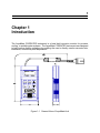
General View of AquaMate Unit ................................................ 1
3-1
Probe Orientation Relative to Flow............................................ 5
3-2
Probe Orientation at a Tee Fitting ............................................. 6
4-1
Front Panel of AquaMate........................................................... 7
4-2
Battery Compartment ................................................................ 8
Table
5-1
Page
CORRATER Multiplier Factors ................................................ 16
Appendix A
Page
A-1
Equivalent Circuit of LPR Probe .............................................. 18
A-2
Typical LPR Current vs. Time Decay Curve ............................ 19
A-3
Operating Rate of LPR Instruments
Corrosion Rate vs. Solution Conductivity............................. 20
A-4
Rohrback Cosasco 3-Electrode
Probe Configuration ............................................................. 21
ii
1
Chapter 1
Introduction
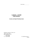
The AquaMate CORRATER instrument is a hand held corrosion monitor for process,
cooling, or potable water systems. The AquaMate CORRATER instrument was designed
to help improve facility operations by enabling the user to directly monitor corrosion rate,
imbalance, conductivity and temperature.
Figure 1-1 General View of AquaMate Unit
2 AquaMate Reference Manual
The AquaMate instrument, in particular, represents a major advance in Portable Linear
Polarization Resistance (LPR) corrosion rate measurement.
An LPR instrument determines the corrosion rate by measuring the current from a small
applied potential difference between two measurement electrodes of the alloy being
monitored. AquaMate extends the range of solution resistance range over which corrosion
rate measurements can be made. This is achieved by the use of a patented AC technique
which automatically compensates for the solution resistance between the corrosion
measuring electrodes. It does this without resorting to a third electrode or correction
curves. AquaMate is however, compatible with all two or three electrode probes already in
use. A discussion of the LPR method of corrosion rate measurement is presented in
Appendix A of this manual.
The AC measurement technique is also used to perform the conductivity measurement.
When a suitable conductivity probe is connected to the instrument, the solution resistance
is measured by the AC technique. The conductivity is then computed from this
measurement.
Temperature measurements are performed by AquaMate when suitable CORROTEMP
CORRATER probes are used. These probes measure temperature with a platinum
resistance temperature device (RTD) located inside the probe near the process end. By
measuring the RTD resistance, AquaMate can calculate and display the temperature of
the water where the probe is installed.
The AquaMate is designed for the convenience of the user. Automatic solution resistance
compensation improves the utility, convenience and accuracy of corrosion rate
measurements. AquaMate also monitors a form of Electrochemical Current Noise (ECN)
between the electrodes called imbalance or pitting tendency. This is a qualitative and very
useful indication of instability in the material surface consistent with pitting or localized
corrosion.
The operator only needs to perform an initial setup to set the cycle time (if other than
automatic), probe multiplier or other parameters of interest. Initial setup is performed via
front panel keys while monitoring the liquid crystal display. A description of user definable
parameters is given in the operation section of this manual. In some cases, initial setup will
not be required since factory defaults have been set.
3
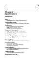
Chapter 2
Specifications
Operational
Input:
Single Channel CORROTEMP CORRATER Probe
Corrosion Rate Ranges:
Autoranging 0.01 to 200 MPY, 0-5.08 mmpy, 0-5080 Fmpy
Conductivity:
(Conductivity probes will be sold separately)
Range: 50-2000 Fmhos/cm (FS/cm)
Accuracy: 10% (excluding probe error)
Temperature Measurement:
Range: 0 deg C to + 260 deg C (0 - 500 deg F)
Accuracy: " 2 deg C (Does not include probe error)
Repeatability: " 1 deg C
Resolution: 0.1 deg C
Imbalance Ranges: (pitting index)
Autoranging 0 to 1000 with mpy units, 0 to 5.08 with
mmpy units, 0 to 5080 with Fmpy units
Operating Range:
Conductivity (Fmhos/cm) divided by corrosion rate (mpy) > 4
Probe Compatibility
Two Electrode CORRATER
Two Electrode CORROTEMP CORRATER
Three Electrode CORRATER
Probe Connectors:
6 Foot Coiled Cable with Standard 6 pin Probe Connector
200 ft. measurement capability
Calibrated Probes:
1 point calibrated test probe (part no. 710617)
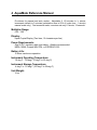
Measurement Cycle Time:
4 AquaMate Reference Manual
Provisions for manual and auto modes. Adjustable 2 -20 minutes in 2 minute
increments, default to 3 minutes (polarization time is 25% of (cycle time - 1 minute)
manual mode only). Fast measure mode, corrosion rate only-1 minute, 15 seconds.
Multiplier Range:
0.25 - 3.00
Display:
Liquid Crystal Display (Two lines, 12 characters per line)
Power Requirements:
One 9V DC, transistor radio type battery. Alkaline recommended.
NEDA 1604A, Duracell MN 1604, or EVEREADY 522
Battery Life:
10 hours continuous operation
Instrument Operating Temperature:
32 deg F - 122 deg F (0 deg C to 55 deg C)
Instrument Storage Temperature:
-4 deg F to 131 deg F (-20 deg C to 55 deg C)
Unit Weight:
14 oz
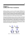
5
Chapter 3
CORRATER Probe Installation
AquaMate is intended to be used with any standard 2-electrode CORRATER probes.
Three electrode probes can also be used, but for simplicity and economy, it is
recommended that 2-electrode probes be used. Probes with replaceable cylindrical
electrodes are generally referred to as "standard" probes, and probes with disc electrodes
are referred to as "flush" probes because the electrodes are flush with the end surface of
the probe. The probes are available in many designs including fixed, adjustable,
retractable and retrievable mounting configurations. Also, probe electrodes are available in
many element and alloy materials. The material selected should closely match the material
of construction of the pipe or vessel for which corrosion information is desired.
Probes should be installed where corrosion is most likely to be greatest so that readings will
truly represent the most aggressive system corrosion rates. Preferably, they should be
located where the liquid flow velocity past the electrode exceeds 1 foot per second (0.3
m/sec.) if it is required to measure corrosion rates representative of a flowing environment.
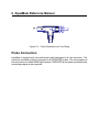
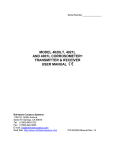
Alignment of the electrodes relative to the direction of process flow is important to obtain
reliable corrosion rate measurements. Proper alignment is with the imaginary line
connecting the centerlines of the two electrodes perpendicular to the direction of the
process flow. Refer to Figure 3-1. With this orientation, one electrode does not "shade" the
other electrode, and both are subject to nearly the same corrosive environment. If a probe
is installed in an elbow fitting, where flow changes direction, position the probe so that the
electrodes "face" the oncoming flow. Refer to Figure 3-2.
Figure 3-1
Probe Orientation Relative to Flow
6 AquaMate Reference Manual
Figure 3-2
Probe Orientation at a Tee Fitting
Probe Connection
AquaMate is supplied with one coiled probe cable terminated in a 6 pin connector. The
connector is suitable for direct connection to all CORRATER probes. The only exception is
interconnection to a Model 6080 High Pressure CORRATER probe where a portable probe
connecting adapter is also required.
7
Chapter 4
Operation
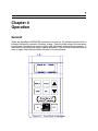
General
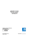
When the AquaMate CORRATER instrument is turned on, the software revision level is
indicated followed by indication of battery voltage. Once the initial setup of the instrument
is performed, the selections remain in effect until individually changed by the operator. If
the indicator is showing near empty, replace the battery. Even if the unit is switched off and
back on again, the instrument does not need to be reconfigured.
Figure 4-1
Front Panel of AquaMate
8 AquaMate Reference Manual
Figure 4-2 Battery Compartment
Initial Setup
Operation of the instrument is accomplished via the front panel keys. A description of each
key and the function it performs follows:
Display:
This key displays the measured corrosion, imbalance, conductivity, and
temperature.
Configure: This key displays the beginning of a list of user definable operating
parameters. Repeatedly pressing this key or the arrow keys allows you to
scroll through the list.
Chapter 4 Operation 9
Edit:
Press this key to begin or end the editing of a parameter. The parameter to
be edited will flash asterisk's in the second line of the display, indicating that
its value can be changed.
Up and Down
Arrow Keys: These keys are used to scroll through the list of parameters. They are also
used in conjunction with the EDIT key to edit specific parameters. If you
press the EDIT key during an editing session, the current value displayed will
be stored permanently. If you want to exit an editing session and return to
the initial parameter value, press the CONFIGURE key. This will interrupt
the editing session without storing any changed parameter values.
Initial setup requires the operator to choose various parameters specific to the process
being measured. Becoming familiar with the following parameter list will identify which
parameters can be changed and provide information about the instruments' capabilities.
Parameter List
The parameter lists are organized in two layers, a basic list for parameters that are
frequently changed and an advanced list. The parameter lists all have similar format. The
top line displays which parameter will be edited. The second line is the parameter value
which can be increased or decreased with the UP and DOWN arrow keys. A brief
description of the parameter list follows:
PROBE MULTIPLIER:
The alloy correction multipliers are adjustable from 0.25 to 3.00.
The factory default is 1.0.
CYCLE TIME: Cycle time is adjustable from 2 to 21 minutes. In addition a FAST or
AUTO mode can be selected. The FAST mode performs a measurement in about 1 minute
10 seconds without performing conductivity, imbalance or temperature measurements.
Solution resistance compensation techniques are not employed in this mode resulting in
faster measurements. The AUTO mode is used to let AquaMate decide how long the cycle
time should be. The factory default is 3 minutes.
PROBE ELEMENT STYLE:
factory default is standard
The available selections are STANDARD and FLUSH. The
PROBE TYPE: The available selections are 2 Electrode, 3 Electrode and CORROTEMP
CORRATER probes. The factory default is 2 Electrode.
ADVANCED OPTIONS: Selecting YES in this mode will present another parameter list,
typically representing parameters that are less frequently used. The factory default is NO.
Advanced Parameter List
ENGINEERING UNITS: The selectable units are either mils per year (MPY), millimeters
per year (mmPY) or micrometers per year (umPY). The factory default is MPY.
TEMPERATURE UNITS: These units are either Celsius or Fahrenheit. The factory
default is degrees Celsius.
10 AquaMate Reference Manual
CONDUCTIVITY DISPLAY: The display of the conductivity measurement can be turned
ON or OFF. The factory default is OFF.
CELL CONSTANT K:
The conductivity cell constant, usually referred to as K factor, is
selectable from 0 to 1.0. For use on standard platinum or stainless steel conductivity
probes with constant of 0.1/cm set K to 0.1. AquaMate measures conductivity by
performing an AC ohms measurement across the probe terminals effectively measuring the
solution resistance. The factory default is 0.1.
NOTE: If taking a conductivity measurement on a CORRATER
probe, values are generally only useable on low corroding alloys
(less than 2 mpy). Calibration can be performed by adjusting the K
factor to provide the correct reading when known buffer solutions
are measured. Rohrback Cosasco Systems provides a stainless steel
conductivity probe, with an embedded RTD temperature sensor, as
part number 032165. This probe will mate with the AquaMate
probe cable without modification. If other conductivity probes are
used, connect one electrode of the conductivity probe to the A and C
terminals of the AquaMate connector, and the other electrode to the
D and F terminals. If an RTD is available, connect one side to the
B and E terminals, the other side to the D and F terminals.
CONDUCTIVITY TEMPERATURE CORRECTION C: The conductivity measurement can
be temperature compensated if desired. The temperature correction factor C is selectable
from 0 to 10 % per degrees Celsius. This compensation has the effect of adjusting the
conductivity reading as if the measurement were performed at 25 degrees Celsius. If
temperature compensation is not desired, a NONE selection is available. The factory
default is 2 %. If taking a conductivity measurement on a CORRATER probe, values are
generally only useable on low corroding alloys (less than 2 mpy). In these cases, carry out
a calibration against a conductivity probe and adjust K1 to provide the correct answer.
RESETTING FACTORY DEFAULT VALUES: The factory default settings are reset by
holding down both arrow keys simultaneously and then applying power to the unit.
AquaMate will display a brief message confirming that the factory defaults have been set
immediately after the power is turned on.
Interpretation of Operating Parameters and Readings
Imbalance Readings:
Imbalance is often referred to as "pitting tendency". It is actually a sample of
Electrochemical Current Noise (ECN) between the two electrodes when the electrodes are
connected to a zero-impedance ammeter effectively measuring the short circuit current.
AquaMate measures this current and displays the results in units of 0.5 FA per square
centimeter of surface area of each electrode (with mpy units and at a multiplier of 1.00).
Regular electrodes are 5.0 square centimeters and therefore one imbalance or pitting unit
Chapter 4 Operation 11
is 2.5 microamps of current (with mpy units and at a multiplier of 1.00). Scaling of this
reading is modified by the probe multiplier and metric unit conversion. The purpose for this
scaling is to make the imbalance reading meaningful when compared to the corrosion rate
reading. It has been found empirically that when the imbalance reading is less than the
corrosion rate reading or close to zero, corrosion is general corrosion with insignificant
pitting. If the imbalance becomes more erratic and similar to or greater than the corrosion
rate value, this is indicative of increased pitting. If the imbalance is up to ten times greater
than the corrosion rate or very erratic this is indicative of a significant pitting which should
be verified by visual inspection of the probe electrodes.
Imbalance can be caused by several factors:
1. Severe pitting. Pitting is generally irregular and non-uniform, consequently the greater
this irregularity or non-uniformity, the greater is the probability of imbalance between
the two electrodes. Pitting is generally accompanied by an increase in imbalance and
also greater irregularity and fluctuation of the reading.
.
2. Improper or inadequate inhibitor film formation. Where filming inhibitors are used and
are not established due to inadequate flow or quantity of inhibitor, imbalance is greater
and shows greater fluctuation. This will often anticipate an increasing corrosion rate
with reducing inhibitor film.
3. Differential scaling or fouling of the electrode.
4. Damage to an electrode or a loosened electrode.
NOTE: Imbalance readings will typically increase when corrosion rate values
increase. There should be concern for pitting when the imbalance increases
significantly without a similar increase in corrosion rate.
Cycle Time Selection
The cycle time setting, when properly set, allows sufficient settling time to make accurate
polarization resistance measurements on the probe. The chemistry of the process
determines the time required for proper settling. In order that measurements are not made
on the "slope of some curve" it is better to have a cycle time greater than that required in
order to provide for some margin in the event that the process shifts in direction.
Corrosion rate measurements on new electrodes may not be representative of those on the
system until the probe has been exposed to the flowing corrodent for several hours up to
one or two days. This length of time is required to allow the electrode surfaces to stabilize
or age to that similar to the material of the plant. New material typically corrodes at a
higher rate during this period. The default cycle time setting for the AquaMate is set to 3
minutes to provide a rapid reading that is convenient for a portable instrument. However, if
greater accuracy is required, it is recommended that cycle time on the AquaMate be set to
automatic. The automatic mode monitors the signal decay characteristic and takes a
reading as soon as it stabilizes. This may take significantly longer than the default time.
Multiplier Selection
12 AquaMate Reference Manual
The AquaMate calibration has been normalized to use a multiplier value of 1.00 when
standard CORRATER mild steel probe electrodes are used. The electrode area is 5
square centimeters for standard electrodes and 0.5 square centimeters for flush electrodes.
If alternate electrode sizes are used or other alloys, the multiplier value will need to be
appropriately changed to provide accurate corrosion rate readings.
Table 5-1 lists the recommended multiplier settings, when using normal size electrodes, for
various commonly used electrode materials. The multiplier should be set to the value
nearest the recommended setting.
If electrodes other than RCS standard (5 cm2) or flush (0.5 cm2) electrodes are used, the
multiplier can be adjusted to compensate for the size. Generally, the multiplier value is
inversely proportional to the electrode area. For example, if 9 square centimeter electrodes
were used with the probe type set to standard, the alloy multiplier value should be adjusted
to the (listed value x 5/9) . For example for 9 cm2 electrode in mild steel set the multiplier to
0.55. (Normal alloy multiplier 1.00 x 5/9 = 0.55)
The multipliers given in the table are based on the common corrosion reactions that occur
with the constituent elements of those alloys. In certain environments, these reactions may
be different and possibly require a different multiplier. In the absence of other information,
the multiplier may be calculated empirically by comparing corrosion rate on the electrodes
determined by weight loss with the average indicated corrosion rate from the instrument
over the same period. The existing multiplier used on the unit is then modified by the ratio:
Corrosion rate by weight loss / Integrated Average corrosion rate from instrument.
13
Chapter 5
Maintenance
Introduction
Routine maintenance of AquaMate is not required except for battery replacement. Probes,
however, should be inspected at intervals and electrodes replaced when required. If a
problem is suspected with the AquaMate instrument, the following tests can be performed
to verify proper operation of the instrument.
Instrument and Probe Cable Test
The instrument is shipped from the factory with CORROTEMP test probes, RCS part
number 710617. These test probes have a nominal 5 MPY at a multiplier of 1.0 corrosion
rate and a 100 deg C temperature simulated within the probe. If acceptable readings are
performed on test probes, then problems are likely to be caused by the process itself or
the probe in service. A fouling problem, for example, can bridge the electrodes and yield
readings outside the normal measurement range of the instrument.
NOTE: Note: Be sure to set the multiplier parameter to 1.0 when
measuring test probes and to return it to its previous setting.
Probe Replacement
Probe replacement is not required except due to damage or deterioration. Replace the
probe if there is physical damage or a low resistance (less than 1 meg ohm) between the
electrodes when disconnected from the electronics.
Probe Cleaning and Electrode Replacement
As supplied from the factory, CORRATER electrodes have grit blasted surfaces and require
no further cleaning before they are used. Probes should be checked at intervals
particularly for conductive debris "shorting" out the electrodes which may be indicated by a
very high corrosion rate reading. They should be cleaned and polished to a dull shine with
an emery cloth. After cleaning, the electrodes should be thoroughly degreased in a
suitable solvent, and handled with a clean cloth or paper towel to prevent contamination.
The important factor is that the electrodes should be REPRESENTATIVE of the conditions
to be monitored. New electrodes may be more responsive to changes in the corrosivity of
the fluid. Electrodes which have been in used for some time will be more representative of
corrosion rates on the more aged plant material, which will have some film build up.
14 AquaMate Reference Manual
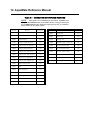
Table 5-1 CORRATER MULTIPLIER FACTORS
NOTE: These factors are recommended for use with the AquaMate when
setting the MULTIPLIER value, as described in Section 4. They are based upon
use of CORRATER electrodes which have surface areas of 5cm2 for "standard"
probes and 0.5 cm2 for "flush" probes.
UNS Code
K03005
Material
Pipe Grade Carbon Steel
Multiplier
UNS Code
1.00
N08800
Incolloy 800
0.89
Material
Multiplier
A91100
Aluminum 1100-0
0.94
N08825
Incolloy 825
0.88
A92024
Aluminum 2024
0.88
N10276
Hastelloy C276
0.86
C11000
Copper 110 ETP Comm. Pure
2.00
R50400
ASTM B-348 Grades 2-4 Titanium
0.75
C44300
CDA 443 Arsenical Admiralty
1.67
S30400
AISI 304 Stainless Steel
0.89
C44500
CDA 445 Phosphorized Adm.
1.68
S31600
AISI 316 Stainless Steel
0.90
C64200
CDA 642 A1 Silicon Bronze
1.48
S31603
AISI 316L Stainless Steel
0.90
C68700
CDA 687 Alum. Brass Arsenical
1.62
S31803
2205 Duplex Stainless Steel
0.89
1.80
S32750
2507 Duplex Stainless Steel
0.88
1.50
Z17001
Grades 1A, 1, 2, 3, or 5 Zinc
1.29
C70610
C71500
CDA 706 90/10 Copper/Nickel
CDA 715 70/30 Copper/Nickel
G41300
AISI 4130 Alloy Steel
1.00
L50045
Lead
2.57
N04400
Monel 400 Nickel
1.13
N05500
Monel K-500 Nickel
1.04
N06022
Hastelloy C22
0.85
N06600
Inconel 600 Nickel
0.95
N08020
Carpenter 20 CB3 SST
0.98
Chapter 5 Maintenance 15
Electrodes should be replaced when the diameter is reduced 1/32 inch (0.794 mm) or
more. CORRATER electrodes are nominally 3/16 inch (4.76 mm) diameter and 1 1/4 inch
(31.75 mm) long when new. As corrosion occurs on the electrodes, their diameter
decreases and begins to significantly affect the accuracy of the corrosion readings. When
installing new or cleaned electrodes on a standard probe body, do not user pliers. They
should be screwed on the mounting studs only "finger-tight", slightly compressing the
rubber O-rings at the base of the studs. Handle the electrodes with a clean cloth or paper
towel to avoid depositing any contaminating oily film. In the event of contamination, a
suitable degreaser can be used to clean the electrodes.
Electrode Pretreatment
Pretreatment of the electrodes may be done is some instances, but is only recommended if
the same type of treatment is used on the plant whenever new material is installed.
Generally, a full strength sample of the treatment chemical is used. The new electrodes
are carefully placed into the solution for a 6-12 hour period and then threaded onto the
probe and placed into service.
Some systems have an initial high level of treatment before the inhibitor rate is reduced to a
maintenance level. The treatment relative to the probe electrodes should be considered.
If the electrodes are installed without pretreatment the corrosion rate indicated will be that
which would occur on new material put in the system. This may typically take a few hours
to a few days to decrease to the normal on-going value. Pretreatment may artificially
protect the material so that it is unrepresentative of any new material that may be put in the
system.
Correlation with Electrodes as Coupons
Weigh the electrodes in the same manner as a coupon would be weighed, on a balance
scale graduated to 0.0001 gram before placing them in service. The coupon should be
placed into service at the same time. After a 30, 60, or 90 day period, remove both, clean
them and analyze them in the same manner. The readings from the instrument integrated
over a period of time, and the data from the electrodes and coupons should correlate.
17
Appendix A
Theory of Operation of CORRATER Systems
CORRATER systems measure the instantaneous corrosion rate of a metal in a
conductive fluid using the linear polarization resistance ("LPR") measurement
technique. Corrosion is an electrochemical process in which electrons are
transferred between anodic and cathodic areas on the corroding metal resulting in
oxidation (corrosion) of the metal at the anode and reduction of cations in the fluid at
the cathode.
Sterns and Geary originally demonstrated that the application of a small polarizing
potential difference (∆E) from the corrosion potential (Ecorr) of a corroding electrode
resulted in a measured current density (imeas) which is related to the corrosion
current density (icorr) by equation (1):
∆E =
imeas
where:
ba bc
(2.303 icorr) (ba + bc)
(1)
ba = Anodic Tafel Slope
bc = Cathodic Tafel Slope
Since the Tafel coefficients are more or less constant for a given metal/fluid
combination, imeas is proportional to icorr which is proportional to the corrosion rate.
Equation (1) and the entire LPR technique are only valid when the polarizing
potential difference is very low (typically up to 20 mV). In this region the curves are
linear, hence the term LPR.
Inspection of Equation (1) shows that the result is a resistance, the Polarization
Resistance, Rp. While strictly speaking, there are both anodic and cathodic Rp
values, which can differ, they are usually assumed to be equal. The resistance to
current flow between anode and cathode on the LPR probe is the sum of both
polarization resistance values and the resistance of the solution between the
electrodes (RS) as shown in Equation (2):
E = imeas (2Rp + RS)
(2)
18 AquaMate Reference Manual
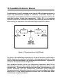
From Equations (1) and (2), obtaining results from the LPR technique would seem to
require only instantaneous readings of resistance. In practice, however, the
determination of polarization resistance is complicated by a capacitance effect at the
metal-fluid interface (double-layer capacitance). Figure A-1 is an equivalent
electrical circuit of the corrosion cell formed by the measuring electrodes and the
fluid, showing the importance of RS and double-layer capacitance effects.
Figure A-1 Equivalent Circuit of LPR Probe
The effect of the double-layer capacitance is to require the direct current flow to
initially charge-up the capacitors, resulting in a decaying exponential current flow
curve vs. time after application of the polarizing potential difference. A typical LPR
current vs. time curve is shown in Figure A-2.
Each metal/fluid interface has its own characteristic capacitance which in turn
determines the amount of time required to obtain valid measurements of icorr and
corrosion rate. The actual time required can vary from a few seconds up to 20
minutes, depending upon the metal/process combination being measured.
Choosing too short a polarization time can result in current readings much higher
than the true icorr thus causing measured corrosion rate to be lower than actual,
sometimes by a significant amount.
Appendix A 19
Figure A-2 Typical LPR Current vs. Time Decay Curve
Solution resistance can also have a significant effect on accuracy if it is relatively
high compared to the polarization resistance. In most industrial water applications,
conductivity of the solution is high and solution resistance is low compared to the
polarization resistance, so imeas is an accurate measure of polarization resistance,
and therefore, corrosion rate.
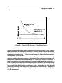
A serious problem develops, however, when the solution resistance increases or the
polarization resistance decreases enough to make the solution resistance a
significant portion of the total resistance to current flow between the electrodes. In
these cases, the accuracy of the LPR measurement is affected. This situation tends
to occur at high corrosion rates (low polarization resistance) and in solutions with
low conductivity (high solution resistance) and is manifested by the indicated
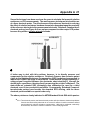
(measured) corrosion rate being lower than the actual corrosion rate. The graph in
Figure A-3 shows the effect of this limitation on the recommended operating range
of LPR instruments.
20 AquaMate Reference Manual
Figure A-3 Operating Range of LPR Instruments
Corrosion Rate vs. Solution Conductivity
Appendix A 21
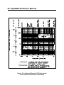
Several techniques have been used over the years to minimize the impact of solution
resistance on LPR measurements. The most common techniques involved the use
of a three electrode probe. The effectiveness of the reference electrode in reducing
the effect of solution resistance has been shown to be dependent upon the proximity
of the reference electrode to the measurement electrode. Rohrback Cosasco threeelectrode probes (see Figure A-4) are unique compared to other major LPR probes
because they utilize a closely-spaced electrode.
F
ig
u
re
A
-4
R
o
h
b
a
c
k
C
s
3
-E
le
tro
d
P
b
C
n
fig
u
a
to
A better way to deal with this problem, however, is to directly measure and
compensate for the solution resistance. Rohrback Cosasco has exclusive patent
rights to the Solution Resistance Compensation (SRC) technique incorporated in
most of the CORRATER range of instruments. In this method, a high-frequency a.c.
voltage signal is applied between the electrodes short-circuiting Rp through the
double-layer capacitance, thereby directly measuring the solution resistance. The
state-of-the-art, patented SRC technology also eliminates the need for a third
electrode, even in low conductivity solutions. Consequently, Rohrback Cosasco's
two-electrode probes have become the standard RCS offering, with the threeelectrode probe available on special order only.
The above points are clearly indicated in ASTM Standard Guide G96 which quotes:
"3.2.8 Two-electrode probes and three-electrode probes with the reference electrode equidistant
from the test and auxiliary electrode do not correct for effects of solution resistance without
special electronic solution resistance compensation. With high to moderate conductivity
environments, this effect of solution resistance is not normally significant.
22 AquaMate Reference Manual
3.2.9
Three-electrode probes compensate for the solution resistance R by varying degrees
depending on the position and proximity of the reference electrode to the test electrode. With
a close-spaced reference electrode, the effects of R can be reduced up to approximately ten
fold. This extends the operating range over which adequate determination of the polarization
resistance can be made.
S
S
3.2.10 A two-electrode probe with electrochemical impedance measurement technique at high
frequency short circuits the double-layer capacitance, C , so that a measurement of solution
resistance R can be made for application as a correction. This also extends the operating
range over which adequate determination of polarization resistance can be made."
dl
S
Imbalance (or Pitting/Index)
In addition to general or uniform corrosion, localized corrosion (pitting) may occur in a
system. This can result in much more rapid failure of a structure than a simple measure of
corrosion rate would indicate. A pit on the metal surface is the result of a localized, high
anodic current density. Positive ions flow away from the pit into the solution and electrons
flow away from the pit into the surrounding metal.
If it were possible to place a zero-impedance ammeter between the pit and the nearby
metal surface, the current in the anode-cathode system of the pit could be measured.
Individual measurements are not practical because the areas are small. Instead, current
flow between the two metallurgically identical electrodes of a CORRATER probe under
short-circuit conditions can be used to indicate pitting tendency. All Rohrback Cosasco
CORRATER instruments include a imbalance/pitting reading. The user should note that
this is a qualitative measurement (or index) and utilize it accordingly. It has proven very
useful in many applications (e.g. cooling water treatment) and offers information not
generally available about a system except by coupons which lag behind actual events and
offer no way of detecting upsets.
If the pitting reading is low compared to the corrosion reading, the pitting problem will
probably be minimal. On the other hand, a pitting reading which is high compared to the
corrosion reading can indicate that pitting or crevice corrosion will be the main form of
corrosive attack. When the readings are about equal, some pitting is indicated, but the pits
will probably be broad and shallow.
23
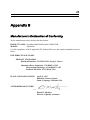
Appendix B
Manufacturer=s Declaration of Conformity
We the manufacturer hereby declare that this product:
PRODUCT NAME: AquaMate Hand Held Portable CORRATER
MODEL:
AAquaMate@
is in full compliance with all applicable EU Product Directives and required standards as noted
below:
EMC DIRECTIVE 89/336/EEC
PRODUCT STANDARDS:
Radiated Emissions - EN 55011:1991, Group 1, Class A
Immunity (Heavy Industrial) - EN 50082-2: 1995
Electrosatatic Discharge - EN 61000-4-2: 1995
Radiated EM Field - ENV 50140: 1994
PLACE AND DATE OF ISSUE:
April 14, 1997
Rohrback Cosasco Systems
Santa Fe Springs, California USA
AUTHORIZED SIGNATURE:
__________________________________
Ronald J. Martinez
Director of Quality Assurance