1
Serial Number______________
MODEL 9020 & 9020-OEM
CORRATER® TRANSMITTER
USER MANUAL
ROHRBACK COSASCO SYSTEMS, INC.
11841 East Smith Avenue
Santa Fe Springs, CA 90670
Tel: (562) 949-0123
(800) 635-6898
Fax: (562) 949-3065
P/N 710900-Manual Rev. E
10/07
© 2002 Rohrback Cosasco Systems, Inc. All rights reserved.
CORRATER® is a registered trademark of Rohrback Cosasco Systems, Inc.
No part of this manual may be reproduced or transmitted in any form or by any means,
electronic or mechanical, including photocopying and recording, for any purpose, without
the express written permission of Rohrback Cosasco Systems, Inc.
i
Contents
Chapter 1
Introduction ............................................................................................. 1
Chapter 2
Specifications ............................................................................................. 3
Chapter 3
Installation ................................................................................................. 5
Chapter 4
Operation ................................................................................................. 11
Appendix A
Probe Multiplier Values ......................................................................... 13
Appendix B
Imbalance Measurement Function of
CORRATER Instruments .................................................................... 15
ii
1
Chapter 1
Introduction
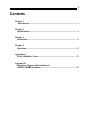
The Model 9020 CORRATER® Transmitter and 9020-OEM Transmitter Module are twowire CORRATER transmitters which are designed to be directly connected to an
industrial plant Distributed Control System (DCS) or other 4-20 milliamp receiver for the
purpose of monitoring corrosion rates and imbalance currents from 2-electrode
CORRATER probes mounted in water systems. Please note that the Model 9020 has no
temperature measurement capability and therefore should not be used with
CORROTEMP® CORRATER probes.
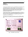
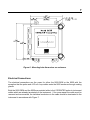
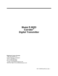
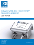
The Model 9020-OEM (Figure 1) is a complete transmitter module for mounting in a
customer provided secondary enclosure while the Model 9020 (Figure 2) consists of the
transmitter module mounted in a NEMA-4X (IP-66) weatherproof enclosure suitable for
field mounting. Either is supplied with a five-foot cable with connector which is
compatible with any CORRATER probe.
The transmitter module is capable of monitoring corrosion rate or imbalance current
using a single loop, or both measurements can be made by powering both transmitter
loops.
Figure 1 - 9020-OEM Transmitter Module
2
CORRATER Transmitter User Manual
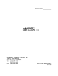
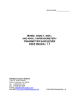
Figure 2 - 9020 Transmitter Installed in Enclosure
Connection to the CORRATER probe to be monitored is made with the six-foot (twometer) cable supplied with the instrument. A 5 MPY (mil per year) test probe is provided
with the instrument for the purpose of verifying proper instrument operation.
3
Chapter 2
Specifications
ELECTRICAL:
#Corrosion Rate Ranges:
0-2, 0-20 and 0-200 MPY
#Imbalance Ranges:
0-2, 0-20 and 0-200 Imbalance Units
#Measurement Cycle Time:
5, 10, 15 and 20 minutes
0.1% of Full Scale
#Resolution:
#Alloy Multiplier Range:
0.2 to 2.99
#Ambient Temperature Range:
-18ΕC to +60ΕC
#Supply Voltage Range:
16-32 VDC at 20 mA.
MECHANICAL:
#Enclosure:
Model 9020-OEM
Model 9020
#Weight:
#Cable:
16 Ga. Aluminum Box
NEMA 4X, IP66
2 lbs. (1 Kg.)
Six-foot (Two-meter) with Type B connector
MISCELLANEOUS:
#Compatibility:
All 2-electrode and 3-electrode CORRATER® probes
4
CORRATER Transmitter User Manual
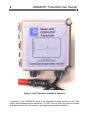
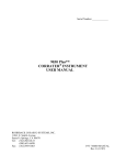
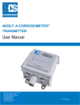
Figure 3 - Dimensions of 9020-OEM
Figure 4 - Dimensions of 9020 NEMA Enclosure
5
Chapter 3
Installation
Unpacking
Check to make sure that the package contains the following items:
#
Model 9020-OEM or Model 9020 CORRATER® transmitter
#
Six-foot probe-to-instrument cable with Type B connector
#
P/N 710920 Test Probe (to verify 9020 instrument operation only)
#
User Manual
Note: All 9020-OEM and 9020 system components are carefully tested, inspected and
packaged prior to shipment. Before proceeding with the installation of the instrument, please
inspect all items for shipping damage and retain any damaged materials to support any claim
against the freight carrier should this become necessary.
Installation Procedure
Installation of the 9020-OEM and 9020 consists of three tasks:
#
#
#
#
Mechanical mounting of the transmitter
Electrical connections to the transmitter and probe
Verification of instrument operation
Selection of parameters for corrosion rate monitoring
Mechanical Mounting
The Model 9020-OEM is intended to me mounted in a customer supplied secondary
enclosure using four #10 machine screws through the mounting feet. Dimensions for the
mounting holes are shown in Figure 5.
6
CORRATER Transmitter User Manual
Figure 5 - Mounting hole dimensions on transmitter.
The Model 9020 is intended to be field mounted on a panel, wall or other vertical surface.
The NEMA 4X enclosure is mounted using four #1/4" machine screws through the mounting
feet. Dimensions for the mounting holes are shown in Figure 6.
7
Figure 6 - Mounting hole dimensions on enclosure.
Electrical Connections
The electrical connections are the same for either the 9020-OEM or the 9020 with the
exception that the probe and 4-20 mA. loop cables enter the 9020 enclosure through sealing
glands.
Both the 9020-OEM and the 9020 are provided with six-foot CORRATER probe-to-instrument
cables which are already terminated on the instrument. If for some reason the cable must be
removed and reconnected, the individual conductors in the cable should be terminated to the
instrument in accordance with Figure 7.
8
CORRATER Transmitter User Manual
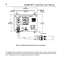
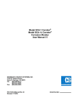
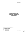
Figure 7 - Drawing showing termination of cable to Probe terminal strip including wire
colors and termination of shield to the ground lug.
If possible, the 9020-OEM and 9020 should be grounded to the system ground in order to
maximize noise immunity. For the 9020-OEM, the ground lead should be connected to the
SHIELD stud where the cable shield is terminated. For the 9020, a separate ground stud is
located directly adjacent to the probe cable gland on the bottom of the enclosure.
A two-conductor cable with shield is recommended for wiring to the 4-20 mA. connections.
If only corrosion rate measurement is required, the connections are made to the two- position
terminal strip labeled CORROSION. If only imbalance measurements are required, the
connections are made to the two-position terminal strip labeled IMBALANCE. If both
measurements are required, connect to both two-position terminal strips as described above.
It is recommended that the shield for the 4-20 mA. loop(s) be grounded at the receiving end,
but left un-terminated at the transmitter end.
9
Verification of Instrument Operation
To verify the proper operation of the 9020-OEM or 9020 instrument, the P/N 710920 Test
Probe is used. The test probe should be connected to the connector on the end of the probe
cable and the switches on the transmitter set in accordance with the following:
Switch
Position
Value
CORROSION RANGE
2
20 MPY
IMBALANCE RANGE
2
20 Imbalance Units
CYCLE TIME RANGE
0
5 Minutes
ALLOY MULTIPLIER
1,0,0
1.00
STANDARD/FLUSH
STANDARD
Apply power to the 4-20 mA. loop and observe the loop current after the measurement cycle
has been completed (approximately 5 minutes). The CORROSION RATE loop current
should be 8.00 ∀0.25 mA. and/or the IMBALANCE loop current should be 4.00 ∀0.1 mA.
Note that the above settings include the switch settings for the transmitter used for monitoring
both CORROSION RATE and IMBALANCE, however it is not necessary to power the second
loop in order to complete the verification testing.
Selection of Parameters for Corrosion Rate Monitoring
To place the transmitter into operation, disconnect the Test Probe and connect the cable to
the CORRATER probe to be monitored.
Set the CORROSION RANGE switch to the position that exceeds the maximum corrosion
rate to be expected, i.e. Position 2 (20 MPY) if the maximum expected rate is 12 MPY. Set
the IMBALANCE RANGE to 0 (No Measurement) if this function is not used.
Set the IMBALANCE RANGE switch to the position that exceeds the maximum imbalance
reading that is expected. The scale factor for this measurement is 0.5 microamperes (ΦA.)
per square centimeter of electrode area. Standard electrodes are 5 square centimeters in
surface area, therefore one imbalance unit is 2.5 ΦA.
Set the CYCLE TIME RANGE for the desired measurement cycle time. For water with
conductivities greater than 100 ΦS., any cycle time of 5 minutes or more should be
satisfactory. For lower conductivity water, or when filming type inhibitors are in use, it is
recommended that the 20 minute cycle time be selected first. After consistent readings are
10
CORRATER Transmitter User Manual
obtained, then a shorter time cycle can be selected as long as the readings do not increase
substantially (>5%) over the readings taken with a 20 minute cycle.
Set the ALLOY MULTIPLIER switches to the appropriate multiplier value for the metal or alloy
of the electrodes as shown in the chart of Appendix 1. The switches represent the three
digits of the multiplier with the left-hand switch selecting the units value (0, 1 or 2); the center
switch selecting the 1/10's value (0.0-0.9); and the right-hand switch selecting the 1/100's
value 0.00-0.09).
Set the STANDARD/FLUSH toggle switch for STANDARD if using a probe with protruding
5.0 square centimeter electrodes or select FLUSH if using a probe with flush 0.5 square
centimeter electrodes.
Enable the power to the loop and after the initial measurement cycle has been completed, the
loop current will be continuously updated to the new value at the end of each measurement
cycle.
11
Chapter 4
Operation
After the initial measurement cycle is completed, the transmitter will update the loop current
at the completion of each measurement cycle. If logging this data, it is not necessary to
sample the loop current more often than once each measurement cycle.
To convert the 4-20 mA. signal into CORROSION RATE in mils per year (MPY), the
conversion formula is as follows:
CORROSION RATE (MPY) = {(IL - 4)/16} X CORROSION RANGE (selected)
To convert the 4-20 mA. Signal into IMBALANCE UNITS, the conversion formula is as
follows:
IMBALANCE (2.5 µA./unit) = {(IL - 4)/16} X IMBALANCE RANGE (selected)
The constant of 2.5 µA. per IMBALANCE UNIT is equivalent to a current density of 0.5 µA.
per square centimeter of electrode area and has been determined empirically so that the
magnitude of the imbalance measurement can be compared with the corrosion rate in mils
per year. For a more detailed description of the imbalance measurement function, please
refer to Appendix B.
12
CORRATER Transmitter User Manual
13
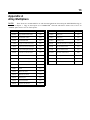
Appendix A
Alloy Multipliers
NOTE:
These factors are recommended for use with the 9020 instrument when setting the MULTIPLIER value, as
®
described in Chapter 3. They are based upon use of CORRATER electrodes which have surface areas of 5cm2 for
2
"standard" probes and 0.5 cm for "flush" probes.
UNS Code
Material
Multiplier
UNS Code
Material
Multiplier
K03005
Pipe Grade Carbon Steel
1.00
N08800
Incolloy 800
0.89
A91100
Aluminum 1100-0
0.94
N08825
Incolloy 825
0.88
A92024
Aluminum 2024
0.88
N10276
Hastelloy C276
0.86
C11000
Copper 110 ETP Comm. Pure
2.00
R50400
ASTM B-348 Grades 2-4 Titanium
0.75
C44300
CDA 443 Arsenical Admiralty
1.67
S30400
AISI 304 Stainless Steel
0.89
C44500
CDA 445 Phosphorized Adm.
1.68
S31600
AISI 316 Stainless Steel
0.90
C64200
CDA 642 A1 Silicon Bronze
1.48
S31603
AISI 316L Stainless Steel
0.90
C68700
CDA 687 Alum. Brass Arsenical
1.62
S31803
2205 Duplex Stainless Steel
0.89
C70610
CDA 706 90/10 Copper/Nickel
1.80
S32750
2507 Duplex Stainless Steel
0.88
C71500
CDA 715 70/30 Copper/Nickel
1.50
Z17001
Grades 1A, 1, 2, 3, or 5 Zinc
1.29
G41300
AISI 4130 Alloy Steel
1.00
L50045
Lead
2.57
N04400
Monel 400 Nickel
1.13
N05500
Monel K-500 Nickel
1.04
N06022
Hastelloy C22
0.85
N06600
Inconel 600 Nickel
0.95
N08020
Carpenter 20 CB3 SST
0.98
14
CORRATER Transmitter User Manual
15
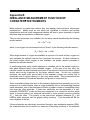
Appendix B
IMBALANCE MEASUREMENT FUNCTION OF
CORRATER INSTRUMENTS
Metal surfaces, no matter how uniform they may appear, have numerous microscopic
imperfections. Metals such as iron alloys are crystalline in structure and surface
imperfections such as small intergranular cavities will tend to grow, especially in liquids
that have large concentrations of dissolved oxygen.
The corrosion processes (iron oxidation) for iron alloys can be described by the following
anodic reaction:
Fe → Fe+2 + 2ewhich, in an oxygen rich environment can be "driven" by the following cathodic reaction:
O2 + 2H2O + 4e → 4 OH
When large amounts of oxygen are available at a portion of a metal surface, oxygen not
only maintains this cathodic reaction, but it promotes the reaction. At other locations on
the metal surface where oxygen is less available, the anodic reaction proceeds to
balance the cathodic reaction.
A small intergranular cavity would represent an excellent site for the anodic reaction to
take place because there is less available oxygen. In the case of an iron alloy, the
reaction causes the rapid localized conversion of iron atoms to ferrous ions since a small
anodic area can be supported by the larger cathodic area. As this iron oxidation
proceeds, the small cavity grows which in turn exposes a larger iron surface that is
essentially void of oxygen causing it to be a very active anode. This process which has
the natural tendency to accelerate describes the growth of a corrosion pit.
Since susceptible pitting sites tend to be randomly distributed and generally are not too
numerous on a metal surface, there is a high probability that on two seemingly identical
metal electrodes, one of the electrodes will have a greater number of susceptible pitting
sites than the other electrode. If these two electrodes are the electrodes of a twoelectrode CORRATER probe and they are submersed in a conductive solution which
tends to promote pitting, one electrode will exhibit a more positive corrosion potential
(Ecorr) than the other. The polarity of the open-circuit potential difference (Eoc) will
indicate which electrode has the greater pitting tendency. That electrode will be the
more negative of the two.
If these electrodes are electrically connected through a zero-resistance ammeter (ZRA),
the measured short-circuit current is a measure of the pitting tendency of the electrode
16
CORRATER Transmitter User Manual
material in the aqueous environment. This is the measurement technique that it is
utilized in CORRATER instruments to provide a qualitative measure of pitting tendency.
In CORRATER instruments, the imbalance (or pitting) units have been established to
be 2.5 microamperes (µa.) which scales to a current density of 0.5µa./cm2 (the
CORRATER electrode surface area is 5 cm2).
The scale factor above was established from empirical data so that the relative
magnitudes of corrosion rates in mils per year (MPY) and imbalance readings could be
compared. At this scale factor, the dominant corrosion mechanism is the one which
exhibits the greater magnitude (i.e. corrosion rate > imbalance indicates more general
corrosion and imbalance > corrosion rate indicates more pitting activity).