1
User's Manual
R-IN32M3 Series
User’s Manual: Modbus stack
・R-IN32M3-EC
・R-IN32M3-CL
All information of mention is things at the time of this document publication, and Renesas
Electronics may change the product or specifications that are listed in this document without
a notice. Please confirm the latest information such as shown by website of Renesas
Electronics.
Document number : R18UZ0030EJ0101
Issue date : Aug 31, 2015
Renesas Electronics
www.renesas.com
Notice
1.
2.
3.
4.
5.
Descriptions of circuits, software and other related information in this document are provided only to illustrate the
operation of semiconductor products and application examples. You are fully responsible for the incorporation of these
circuits, software, and information in the design of your equipment. Renesas Electronics assumes no responsibility for
any losses incurred by you or third parties arising from the use of these circuits, software, or information.
Renesas Electronics has used reasonable care in preparing the information included in this document, but Renesas
Electronics does not warrant that such information is error free. Renesas Electronics assumes no liability whatsoever
for any damages incurred by you resulting from errors in or omissions from the information included herein.
Renesas Electronics does not assume any liability for infringement of patents, copyrights, or other intellectual property
rights of third parties by or arising from the use of Renesas Electronics products or technical information described in
this document. No license, express, implied or otherwise, is granted hereby under any patents, copyrights or other
intellectual property rights of Renesas Electronics or others.
You should not alter, modify, copy, or otherwise misappropriate any Renesas Electronics product, whether in whole or
in part. Renesas Electronics assumes no responsibility for any losses incurred by you or third parties arising from such
alteration, modification, copy or otherwise misappropriation of Renesas Electronics product.
Renesas Electronics products are classified according to the following two quality grades: "Standard" and "High
Quality". The recommended applications for each Renesas Electronics product depends on the product's quality grade,
as indicated below.
"Standard":
Computers; office equipment; communications equipment; test and measurement equipment; audio
and visual equipment; home electronic appliances; machine tools; personal electronic equipment;
and industrial robots etc.
"High Quality": Transportation equipment (automobiles, trains, ships, etc.); traffic control systems; anti-disaster
systems; anti-crime systems; and safety equipment etc.
Renesas Electronics products are neither intended nor authorized for use in products or systems that may pose a
direct threat to human life or bodily injury (artificial life support devices or systems, surgical implantations etc.), or may
cause serious property damages (nuclear reactor control systems, military equipment etc.). You must check the quality
grade of each Renesas Electronics product before using it in a particular application. You may not use any Renesas
Electronics product for any application for which it is not intended. Renesas Electronics shall not be in any way liable
for any damages or losses incurred by you or third parties arising from the use of any Renesas Electronics product for
which the product is not intended by Renesas Electronics.
6. You should use the Renesas Electronics products described in this document within the range specified by Renesas
Electronics, especially with respect to the maximum rating, operating supply voltage range, movement power voltage
range, heat radiation characteristics, installation and other product characteristics. Renesas Electronics shall have no
liability for malfunctions or damages arising out of the use of Renesas Electronics products beyond such specified
ranges.
7. Although Renesas Electronics endeavors to improve the quality and reliability of its products, semiconductor products
have specific characteristics such as the occurrence of failure at a certain rate and malfunctions under certain use
conditions. Further, Renesas Electronics products are not subject to radiation resistance design. Please be sure to
implement safety measures to guard them against the possibility of physical injury, and injury or damage caused by fire
in the event of the failure of a Renesas Electronics product, such as safety design for hardware and software including
but not limited to redundancy, fire control and malfunction prevention, appropriate treatment for aging degradation or
any other appropriate measures. Because the evaluation of microcomputer software alone is very difficult, please
evaluate the safety of the final products or systems manufactured by you.
8. Please contact a Renesas Electronics sales office for details as to environmental matters such as the environmental
compatibility of each Renesas Electronics product. Please use Renesas Electronics products in compliance with all
applicable laws and regulations that regulate the inclusion or use of controlled substances, including without limitation,
the EU RoHS Directive. Renesas Electronics assumes no liability for damages or losses occurring as a result of your
noncompliance with applicable laws and regulations.
9. Renesas Electronics products and technology may not be used for or incorporated into any products or systems
whose manufacture, use, or sale is prohibited under any applicable domestic or foreign laws or regulations. You should
not use Renesas Electronics products or technology described in this document for any purpose relating to military
applications or use by the military, including but not limited to the development of weapons of mass destruction. When
exporting the Renesas Electronics products or technology described in this document, you should comply with the
applicable export control laws and regulations and follow the procedures required by such laws and regulations.
10. It is the responsibility of the buyer or distributor of Renesas Electronics products, who distributes, disposes of, or
otherwise places the product with a third party, to notify such third party in advance of the contents and conditions set
forth in this document, Renesas Electronics assumes no responsibility for any losses incurred by you or third parties as
a result of unauthorized use of Renesas Electronics products.
11. This document may not be reproduced or duplicated in any form, in whole or in part, without prior written consent of
Renesas Electronics.
12. Please contact a Renesas Electronics sales office if you have any questions regarding the information contained in
this document or Renesas Electronics products, or if you have any other inquiries.
(Note 1) "Renesas Electronics" as used in this document means Renesas Electronics Corporation and also includes its
majority-owned subsidiaries.
(Note 2) "Renesas Electronics product(s)" means any product developed or manufactured by or for Renesas Electronics.
Instructions for the use of product
In this section, the precautions are described for over whole of CMOS device.
Please refer to this manual about individual precaution.
When there is a mention unlike the text of this manual, a mention of the text takes first priority
1.
Handling of Unused Pins
Handle unused pins in accord with the directions given under Handling of Unused Pins in the manual.
- The input pins of CMOS products are generally in the high-impedance state. In operation with an unused pin in the
open-circuit state, extra electromagnetic noise is induced in the vicinity of LSI, associated shoot-through current
flows internally, and malfunctions occur due to the false recognition of the pin state as an input signal become
possible. Unused pins should be handled as described under Handling of Unused Pins in the manual.
2.
Processing at Power-on
The state of the product is undefined at the moment when power is supplied.
- The states of internal circuits in the LSI are indeterminate and the states of register settings and pins are undefined
at the moment when power is supplied.
In a finished product where the reset signal is applied to the external reset pin, the states of pins are not guaranteed
from the moment when power is supplied until the reset process is completed.
In a similar way, the states of pins in a product that is reset by an on-chip power-on reset function are not
guaranteed from the moment when power is supplied until the power reaches the level at which resetting has been
specified.
3.
Prohibition of Access to Reserved Addresses
Access to reserved addresses is prohibited.
- The reserved addresses are provided for the possible future expansion of functions. Do not access these addresses;
the correct operation of LSI is not guaranteed if they are accessed.
4.
Clock Signals
After applying a reset, only release the reset line after the operating clock signal has become stable. When switching
the clock signal during program execution, wait until the target clock signal has stabilized.
- When the clock signal is generated with an external resonator (or from an external oscillator) during a reset, ensure
that the reset line is only released after full stabilization of the clock signal. Moreover, when switching to a clock
signal produced with an external resonator (or by an external oscillator) while program execution is in progress, wait
until the target clock signal is stable.
・ ARM, AMBA, ARM Cortex, Thumb and ARM Cortex-M3 are a trademark or a registered trademark of ARM Limited
in EU and other countries.
・ Ethernet is a registered trademark of Fuji Zerox Limited.
・ IEEE is a registered trademark of the Institute of Electrical and Electronics Engineers, Inc.
・ Modbus is a registered trademark of Schneider Electric.
・ Additionally all product names and service names in this document are a trademark or a registered trademark
which belongs to the respective owners.
・ Real-Time OS Accelerator and Hardware Real-Time OS is based on Hardware Real-Time OS of “ARTESSO”
made in KERNELON SILICON Inc.
How to use this manual
Purpose and target readers
This manual is intended for users who wish to understand the functions of Industrial Ethernet network LSI “RIN32M3-EC/CL” for designing application of it.
It is assumed that the reader of this manual has general knowledge in the fields of electrical engineering, logic circuits,
and microcontrollers.
Particular attention should be paid to the precautionary notes when using the manual. These notes occur
within the body of the text, at the end of each section, and in the Usage Notes section.
The revision history summarizes the locations of revisions and additions. It does not list all revisions. Refer to
the text of the manual for details.
The mark “<R>” means the updated point in this revision. The mark “<R>” let users search for the updated
point in this document.
Related
The related documents indicated in this publication may include preliminary versions. However,
Documents
preliminary versions are not marked as such. Please be understanding of this beforehand. In addition,
because we make document at development, planning of each core, the related document may be the
document for individual customers. Last four digits of document number(described as ****) indicate
version information of each document. Please download the latest document from our web site and
refer to it.
The document related to R-IN32M3 Series
Document name
Document number
R-IN32M3 Series Datasheet
R18DS0008EJ****
R-IN32M3-EC User’s Manual
R18UZ0003EJ****
R-IN32M3-CL User’s Manual
R18UZ0005EJ****
R-IN32M3 Series User’s Manual Peripheral function
R18UZ0007EJ****
R-IN32M3 Series Programming Manual (Driver edition)
R18UZ0009EJ****
R-IN32M3 Series Programming Manual (OS edition)
R18UZ0011EJ****
R-IN32M3 Series User's Manual TCP/IP stack
R18UZ0019EJ****
R-IN32M3 Series User's Manual Modbus stack
This Manual
Notation of Numbers and Symbols
Weight in data notation
:
Left is high-order column, right is low-order column
Active low notation:
xxxZ
(capital letter Z after pin name or signal name)
or
xxx_N
or
xxnx
(capital letter _N after pin name or signal name)
(pin name or signal name contains small letter n)
Note:
explanation of (Note) in the text
Caution:
Item deserving extra attention
Remark:
Supplementary explanation to the text
Numeric notation:
Binary … xxxx , xxxxB or n’bxxxx (n bits)
Decimal … xxxx
Hexadecimal … xxxxH or n’hxxxx (n bits)
Prefixes representing powers of 2 (address space, memory capacity):
K (kilo)… 210 = 1024
M (mega)… 220 = 10242
G (giga)… 230 = 10243
Data Type:
Word … 32 bits
Halfword … 16 bits
Byte … 8 bits
Contents
1.
2.
3.
Overview ........................................................................................................................................................ 1
1.1
Features ............................................................................................................................................................... 1
1.2
Sample soft’s varieties ........................................................................................................................................ 2
1.3
Development environment .................................................................................................................................. 3
1.3.1
Development tools ..................................................................................................................................... 3
1.3.2
Evaluation board ........................................................................................................................................ 4
1.4
Resource Requirements ...................................................................................................................................... 5
1.5
Networking Aspects ............................................................................................................................................ 5
1.6
Concurrency Issues ............................................................................................................................................. 5
Basic concepts of R-IN32M3 Modbus stack.................................................................................................. 6
2.1
Supported Protocol standards ............................................................................................................................. 6
2.2
Design Methodology........................................................................................................................................... 7
System Architecture – Modbus Serial Protocol Stacks ................................................................................. 8
3.1
4.
3.1.1
Application Interface Layer ....................................................................................................................... 9
3.1.2
Packet Framing and Parsing Layer .......................................................................................................... 15
3.1.3
Connection management, Frame Send and Receive Layer ...................................................................... 16
3.1.4
Stack Configuration and Management Module ....................................................................................... 17
System Architecture – Modbus TCP Protocol Stacks ................................................................................. 20
4.1
5.
Module Decomposition....................................................................................................................................... 9
Module Decomposition..................................................................................................................................... 22
4.1.1
Application Interface Layer ..................................................................................................................... 22
4.1.2
Packet Framing and Parsing Layer .......................................................................................................... 28
4.1.3
Connection management, Frame Send and Receive Layer ...................................................................... 29
Description of application programming interface ....................................................................................... 34
5.1
User Interface API ............................................................................................................................................ 34
5.1.1
Modbus TCP/IP ....................................................................................................................................... 34
5.1.2
Modbus Serial .......................................................................................................................................... 46
5.2
Internal API ...................................................................................................................................................... 70
5.2.1
Packet Framing and Parsing API ............................................................................................................. 70
5.2.2
Stack Configuration and Management API ............................................................................................. 93
Contents -1
5.2.3
6.
Implementation .......................................................................................................................................... 111
6.1
Server mode ........................................................................................................................................... 111
6.1.2
Gateway mode ....................................................................................................................................... 114
Modbus RTU/ASCII ....................................................................................................................................... 118
6.2.1
Slave mode............................................................................................................................................. 118
6.2.2
Master mode .......................................................................................................................................... 122
Tutorial by sample application ................................................................................................................... 123
7.1
Modbus TCP server communication .............................................................................................................. 123
7.1.1
Overview of sample project ................................................................................................................... 123
7.1.2
Hardware connection ............................................................................................................................. 123
7.1.3
Board IP address setting ........................................................................................................................ 124
7.1.4
Demonstration........................................................................................................................................ 127
7.2
Modbus RTU/ASCII slave communication .................................................................................................... 132
7.2.1
Overview of sample project ................................................................................................................... 132
7.2.2
Hardware connection ............................................................................................................................. 132
7.2.3
Demonstration........................................................................................................................................ 134
7.3
Modbus RTU/ASCII master communication ................................................................................................. 142
7.3.1
Overview of sample project ................................................................................................................... 142
7.3.2
Hardware connection ............................................................................................................................. 142
7.3.3
Demonstration........................................................................................................................................ 142
7.4
8.
Modbus TCP ................................................................................................................................................... 111
6.1.1
6.2
7.
Gateway mode API ................................................................................................................................ 102
Modbus TCP server – RTU/ASCII master gateway communication ............................................................. 146
7.4.1
Overview of sample project ................................................................................................................... 146
7.4.2
Hardware connection ............................................................................................................................. 146
7.4.3
Demonstration........................................................................................................................................ 147
Issue and Limitations ................................................................................................................................. 149
Contents -2
R-IN32M3 Series
User’s Manual: Modbus stack
1.
R18UZ0030EJ0101
Aug 31, 2015
Overview
This document explains Modbus protocol stacks for R-IN32M3 series. In here, Modbus protocol is meant as Modbus
TCP which is an Ethernet based protocol and Modbus RTU, and Modbus ASCII protocol, which is based on serial
communication like as RS-485, RS-232C, and RS-422.
This document is intended to be read by users who are developing a Modbus application using the R-IN32M3 Modbus
protocol stack. This document will thus serve as a guide in implementing a Modbus application using the R-IN32M3
Modbus protocol stack. So the function summary and Application Programming Interface (API) and application samples
of Modbus protocol stack are described in this document.
1.1
Features
R-IN32M3 Modbus protocol stack allows fast and easy development of the following applications.
Modbus RTU slave
Modbus ASCII slave
Modbus RTU master
Modbus ASCII master
Modbus TCP server
Modbus TCP gateway
Supported classes and function codes are followings.
Support of the Modbus conformance classes 0, 1 and part of class 2
Supported function codes:
- Read Coils (FC 1)
- Read Discrete Inputs (FC 2)
- Read Holding Registers (FC 3)
- Read Input Registers (FC 4)
- Write Single Coil (FC 5)
- Write Single Register (FC 6)
- Write Multiple Coils (FC 15)
- Write Multiple Registers (FC 16)
- Read/Write Multiple Registers (FC 23)
R18UZ0030EJ0101
Aug 31, 2015
Page 1 of 149
R-IN32M3 Series
1.2
1. Overview
Sample soft’s varieties
User can use the 2 types of sample software of Modbus stack, named “limited version” and “official version”.
For both, the contents and supported level are same. The differences are mainly binarization of code and some
restrictions for setting.
The following is the overview of the difference between “limited version” and “official version”.
Table 1.1 Difference for version
Items
Limited version
Official version
Supported protocol
Supported Modbus TCP server , RTU/ASCII master, or slave
Function
- For TCP, gateway
Since based on TCP/IP “evaluation
version”, There are some restriction
(e.g. Protocol stack configurations) Note1
- For RTU/ASCII
- For TCP, gateway
Since based on TCP/IP “commercial
version”, there are no restriction.
- For RTU/ASCII
No difference functionally
No difference functionally
Code binarization
Core part of Modbus stack is object code.
Source code except for the core of TCP/IP,
And TCP/IP, UDP/IP part is same as
UDP/IP part.
evaluation version of TCP/IP stack from
Renesas.
Download from Renesas’s website Note2
How to get
Please contact to Renesas.
Note1 The detail is written in the chapter 1 of User’s manual TCP/IP stack.
Note2 Limited version is available to download from the following site.
http://www.renesas.com/products/soc/assp/fa_lsi/multi_protocol_communication/rin32m3/peer/sample_software.jsp
The limited version is suitable for initial evaluation and realizes easy to touch, but for mass production, please ask to
get the official version.
R18UZ0030EJ0101
Aug 31, 2015
Page 2 of 149
R-IN32M3 Series
1.3
1. Overview
Development environment
The development environment of Modbus protocol stack is described here.
1.3.1
Development tools
Development tools for this stack are shown in Table 1.2.
Table 1.2 Development tools
Tool Chain
ARM
IDE
-
Compiler
Debugger
ICE
RealView Developer Suite
microVIEW-PLUS
adviceLUNA 2.03-00
V4.1
Ver.5.11PL3
(Yokogawa Digital
(ARM)
(Yokogawa Digital
Computer Corporation)
Computer Corporation)
GNU
-
Sourcery G++ Lite 2012.09-
microVIEW-PLUS
adviceLUNA 2.03-00
63
Ver.5.11PL3
(Yokogawa Digital
(Mentor Graphics)
(Yokogawa Digital
Computer Corporation)
Computer Corporation)
KEIL
IAR
MDK-ARM
MDK-ARM
MDK-ARM
ULINK
(KEIL)
(KEIL)
(KEIL)
(KEIL)
Embedded Workbench for
Embedded Workbench for
Embedded Workbench for
i-Jet
ARM V7.30.1
ARM V7.30.1
ARM V7.30.1
JTAGjet-Trace-CM
(IAR Systems)
(IAR Systems)
(IAR Systems)
(IAR Systems)
R18UZ0030EJ0101
Aug 31, 2015
Page 3 of 149
R-IN32M3 Series
1.3.2
1. Overview
Evaluation board
Modbus stack sample application can be worked on the following evaluation boards for R-IN32M3. Regarding a more
information for each evaluation boards, please look Renesas or IAR or TESSERA TECHNOLOGY INC.s’ web site.
[Supported evaluation board]
- Modbus TCP protocol
・
TS-R-IN32M3-EC
: by TESSERA TECHNOLOGY INC.
・
TS-R-IN32M3-CL
: by TESSERA TECHNOLOGY INC.
・
TS-R-IN32M3-CEC
: by TESSERA TECHNOLOGY INC.
・
KSK-RIN32M3EC-LT-IL : by IAR KickStart kit by IAR AB.
- Modbus RTU/ASCII protocol
・
TS-R-IN32M3-EC
: by TESSERA TECHNOLOGY INC.
・
TS-R-IN32M3-CL
: by TESSERA TECHNOLOGY INC.
・
TS-R-IN32M3-CEC
: by TESSERA TECHNOLOGY INC.
Caution For RS-485 communication with Modbus RTU/ASCII protocol, user should prepare the
RS485 transceiver IC or module, and connect related signal as follows.
P20 (RXD0) : to TX,
P21 (TXD0) : to RX,
RP17(GPIO) : to DE(/RE)
For Modbus RTU/ASCII communication, the example of hardware connection is described in Chapter 7. Please refer
its chapter.
R18UZ0030EJ0101
Aug 31, 2015
Page 4 of 149
R-IN32M3 Series
1.4
1. Overview
Resource Requirements
The hardware RTOS must be available to run the stack.
The code running along with the Modbus Serial Stacks must not use the one timer channel, as it is used by the stack
for packet timing. If user wants to assign some other timer channel for the stack it has to be done by the stack
initialization.
The stack uses one channel the UART in the Modbus serial communications. If the user wants to change the UART
channel it has to be done by the stack initialization.
The user has to assign a GPIO Pin for controlling the RS485 transceiver and it must be available to the stack. It has
to be done by the stack initialization.
1.5
Networking Aspects
The Modbus Serial stack can communicate over standard RS485 networks.
The Modbus TCP Stack is capable of communicating over standard Ethernet networks.
1.6
Concurrency Issues
The stack uses a UART channel, a timer channel and a GPIO pin of the chip while running in serial mode. These
interfaces will not be available to other programs when the stack is running.
The stack consumes some capabilities of the hardware RTOS.
If the stack is running in the Slave mode, the user has to ensure the proper handshaking of the stack and the task that
updates the Modbus application objects.
- In Slave mode, the user has to write the function for accessing the Modbus objects and map it to the Modbus
function codes by using the function ‘Modbus_slave_map_init()’.
- While writing the function the user has to ensure that two or more tasks will not access the memory at a time.
R18UZ0030EJ0101
Aug 31, 2015
Page 5 of 149
R-IN32M3 Series
2. Basic concepts of R-IN32M3 Modbus stack
2.
Basic concepts of R-IN32M3 Modbus stack
2.1
Supported Protocol standards
This stack has got the capability to address the requirements of both Modbus Master/Client and Modbus Slave/Server.
Along with these the stack has got the capability to communicate with Modbus RTU, Modbus ASCII and Modbus TCP
networks. But it doesn’t have the capability to function as a Modbus TCP Client stack.
Based on the different modes, the stack can be considered as the composition of the following six stacks,
Modbus RTU Master Stack.
Modbus RTU Slave Stack.
Modbus ASCII Master Stack.
Modbus ASCII Slave Stack.
Modbus TCP Server Stack.
Modbus TCP Server Gateway Stack
Provision is given to the user to select the stack mode in their project. Along with this, nine Modbus function codes are
also supported in these stacks. Following are the function codes supported in these stacks,
1(0x01) – Read coils
2(0x02) – Read discrete input
3(0x03) – Read holding registers
4(0x04) – Read input registers
5(0x05) – Write single coil
6(0x06) – Write single register
15(0x0F) – Write multiple coils
16(0x10) – Write multiple registers
23(0x17) – Read/Write multiple registers
R18UZ0030EJ0101
Aug 31, 2015
Page 6 of 149
R-IN32M3 Series
2.2
2. Basic concepts of R-IN32M3 Modbus stack
Design Methodology
1. Choose a necessary in order to implement functions on network, a protocol stack is a prescribed hierarchy of
software layers. The following figure shows hiearachy in this stack.
2. This stack creates a task by using the capability of the hardware RTOS. The stack is to use in the multi threaded
projects using the RTOS.
3. This stack must not use more than one timer channel for Modbus frame timing.
User application
Modbus Master/Client
Modbus Server/Slave
Modbus
Application Objects
R-IN32M3 Modbus Protocol stack
Interface driver
and stack
Serial Inerface (RS485/RS232)
TCP/IP stack
Ethernet Interface
Figure 2.1 Overview of R-IN32M3 Modbus stack <R>
R18UZ0030EJ0101
Aug 31, 2015
Page 7 of 149
R-IN32M3 Series
3.
3. System Architecture – Modbus Serial Protocol Stacks
System Architecture – Modbus Serial Protocol Stacks
Figure 3.1 shows the overall architecture of the Modbus Protocol Stack. As shown in the diagram the stack is divided
in to four functional layers.
The stack is designed in such a way that it can be used to realize both server/slave and client/master applications by
setting the required configuration. The stack can be configured to support any one of Modbus RTU and Modbus ASCII
modes at a time. For selecting the desired stack mode and client / server functions, initialization API is provided which
the user can modify.
Figure 3.1 Modbus Stack Architecture <R>
Subsequent sections contain the information of the layered architecture.
R18UZ0030EJ0101
Aug 31, 2015
Page 8 of 149
R-IN32M3 Series
3.1
3. System Architecture – Modbus Serial Protocol Stacks
Module Decomposition
Based on the functionality, the stack is divided in to the following layers
Application Interface Layer as the top layer, which directly interacts with the user application in both master and slave
modes.
Packet Framing and Parsing Layer as the middle layer, this layer is responsible for framing, parsing and validating the
Modbus frames.
Connection management, Frame Send and Receive Layer as the bottom layer, which manages the logical connections
and sending and receiving of the Modbus frames.
Across these three layers lies the Configuration Layer, this is the layer which contains the necessary configuration
APIs. Below sections detail the different layers and design of these layers.
3.1.1
Application Interface Layer
Application interface layer contains the necessary functions to interact with the user application. It also contains a
thread that maintains the stack states. Based on the configured stack mode, either Master or Slave, the thread works in
different ways and makes it possible to provide, to the user, the functionalities required in that mode. This layer of the
stack is same for the communication modes RTU and ASCII.
The main ‘Application Interface Layer’ components, specific to the Modbus Server/Slave mode, are the Serial task and
the Modbus_serial_slave_map_init() function. Using the Modbus_serial_slave_map_init() API, the user application
registers the callback functions to be invoked when a valid Modbus request with a particular function code is received.
The parsing of the request message and framing the response are running in the context of the Serial task. When a
valid Modbus request is received, the task will invoke the appropriate call back handler function. The task is designed
such that the response is passed back to the master only on receiving the response from the callback handler.
Remark The call back handler is user application provided and care must be taken to ensure that the
function returns within a stipulated maximum interval. If the function does not return due to
some error, there are chances that Modbus server will no longer be able to accept new
commands.
The main ‘Application Interface Layer’ components, specific to the Modbus Master/Client mode are the Serial task
and the User Application Interface APIs. Serial task starts to run when the user initialized the stack, and the user
application calls the interface API for Modbus transactions.
The user application calls User Application Interface APIs to request the stack to send Modbus requests to the Modbus
slave devices. The Serial task receives the request and processes it.
Calls to these APIs can be blocking or non-blocking. If the user provided a call-back function in the arguments, the
function call will be non-blocking and the serial task calls the user provided function on reception of a response or
timeout occur. If the user didn’t provide a call-back function, these APIs block till receiving a replay from slave device or
timeout occur.
R18UZ0030EJ0101
Aug 31, 2015
Page 9 of 149
R-IN32M3 Series
3.1.1.1
3. System Architecture – Modbus Serial Protocol Stacks
Modbus Serial Task
A common task named serial task is used for both Modbus Master and Slave Stack irrespective of mode (RTU/ASCII).
Depending on the configured stack mode, the task functions as either Master or Slave task.
For example, if the stack mode is defined as Modbus RTU Master, then the serial task will function as master task.
This is done by switching between two states defined for Master and Slave.
The Figure 3.2 shows the state transition diagram of the Serial task functioning as slave. The function
Modbus_serial_stack_init() initializes the Serial Task, on successful initialization the task waits for a message using a
mailbox. Depending on the message type received in mailbox it functions either as Master or Slave. The task remains in
that state till receiving a Modbus request from the Modbus Master when it functions as a Slave task.
On receiving a request from the client, the task does the following activities,
Parse and validate the received packet.
If successful verification of the packet integrity, frames a response packet and sends it to the master device.
R18UZ0030EJ0101
Aug 31, 2015
Page 10 of 149
R-IN32M3 Series
3. System Architecture – Modbus Serial Protocol Stacks
Figure 3.2 Functioning of Modbus Serial Task as Slave <R>
R18UZ0030EJ0101
Aug 31, 2015
Page 11 of 149
R-IN32M3 Series
3. System Architecture – Modbus Serial Protocol Stacks
The Figure 3.3 Figure 3.2 shows the state transition diagram of the Serial task functioning as master. Modbus Serial
Task starts running when the user initializes the stack by calling the function named ‘Modbus_serial_stack_init ()’. After
initialization serial task will wait for the message. The user application calls the User Application Interface APIs, to
request the serial task for Modbus transactions with the slave devices. When the task received a request, it does the
following activities.
Prepare a Modbus request packet and send it to the Modbus Slave device.
If the request sent was a broadcast request, the task waits up to the ‘Turnaround Delay’ and start to wait for another
request from the user.
If the request sent was a unicast request, the task waits for a response from the slave device until 'Response Timeout'
interval.
If the task received a valid response from the slave device within the ‘Response timeout’ expires, it updates the
received data to the user application.
If the task didn’t receive a response within ‘Response Timeout’ interval, the task retries the same request up to a
configured number of max retry counts.
If the task didn’t receive a response to the retries also, then the task updates the user application with the timeout
information.
The user application can provide a callback handler along with the function call if it requires notification when the
command request processing is completed. In this case, the function call will not block and application developer can
perform other tasks while the request is completed. If a callback function is not provided, the function call will be a
blocking call.
R18UZ0030EJ0101
Aug 31, 2015
Page 12 of 149
R-IN32M3 Series
3. System Architecture – Modbus Serial Protocol Stacks
Figure 3.3 Functioning of Modbus Serial Task as Master <R>
R18UZ0030EJ0101
Aug 31, 2015
Page 13 of 149
R-IN32M3 Series
3.1.1.2
(1)
3. System Architecture – Modbus Serial Protocol Stacks
Error identification and reporting
Modbus RTU/ASCII Slave
For unicast requests, the Serial task will generate an exception response and send it back to the Master, when
received a request for a function code to which the user has not registered a callback function.
The call-back function written by the user has to generate exceptions for the requests for registers or coils those are
not implemented.
The initialization API performs a basic level validation on the initialization parameters and returns the status, while
initializing the stack.
For broadcast requests, response will not be sent to client for all requests.
(2)
Modbus RTU/ASCII Master
The API functions will perform a basic level validation on the parameters given to it.
The task returns timeout error if it doesn’t receive a response to the request after a number of retries.
Memory is allocated dynamically for packet construction. Error is reported if the memory can not be ensured.
R18UZ0030EJ0101
Aug 31, 2015
Page 14 of 149
R-IN32M3 Series
3.1.2
3. System Architecture – Modbus Serial Protocol Stacks
Packet Framing and Parsing Layer
This is the stack layer which does the required packet framing and parsing activities. It contains functions and data
structures for framing the Modbus packets, parsing the packet, sending packet, receiving packet, and validating the
received packets. The implementation of these functions is different for Modbus RTU and Modbus ASCII modes, but
functions of a particular communication mode are used in both Master and Slave modes. Also, since Modbus packet is
processed internally in RTU format, it will be processed is converted to RTU format even in the case of ASCII mode.
(1)
Parsing receive packet
In the case of ASCII mode, perform the packet conversion from ASCII format to RTU format.
If length check, packet integrity and slave ID checks fail, discards the received packet.
After successful verification of the packet integrity, slave ID and the request data, invokes the user registered
function to process the request.
When received a unicast request, prepares an exception response and sends it to the master on failure of function
code and request data validation.
When received a broadcast request, the received packet is accepted as a normal packet if the write function code, but
it does not send a response message to the master device. On the other, the received packet is if read function code,
and discards the request packet as invalid slave ID.
(2)
Framing send packet
In the case of master mode, the request packet will be constructed based on the content generated by the API. In the
case of slave mode, the response packet will be constructed based on the content generated by the API. CRC / LRC
will be added to constructed packet. In the case of ASCII mode, since the stack is processing internally in RTU format,
converted to ASCII is done from the RTU.
3.1.2.1
Error Identification and Reporting
Packet length and specified data and slave ID in the Receive and Transmit packets are verified whether they comply
with the protocol based on the function code.
Packet validation function verifies the integrity of the received packet using CRC/LRC filled in the packet.
Memory is allocated dynamically for framing packet. Error is reported if the memory can not be ensured.
R18UZ0030EJ0101
Aug 31, 2015
Page 15 of 149
R-IN32M3 Series
3.1.3
3. System Architecture – Modbus Serial Protocol Stacks
Connection management, Frame Send and Receive Layer
This is the layer which contains the functions and data structures for sending and receiving data through the
communication interface. Management of frame timing in the case of serial interface comes in this layer.
3.1.3.1
Serial Receive Task
The serial receive task starts running when the Modbus Serial Stack is initialized. An event is being registered in the
Hardware ISR table for UART and Timer interrupts. The serial receive task waits for the event flag to be set with the
pattern defined in the hardware ISR.
If the UART interrupt occurred, each byte is read using the driver function uart_read(). After the successful reception
of character, depending on the stack mode either Modbus_ascii_recv_char() or Modbus_rtu_recv_char() is invoked. The
characters are stored in a buffer within these functions.
If the timer interrupt occurred, Modbus_timer_handler() is invoked. Determining the frame timing is done in this
function.
3.1.3.2
Modbus Serial Interface Configuration
In this mode, UART interface of the chip is configured to send and receive packets as per the configuration
parameters provided while initializing the stack.
If an error occurs during the reception operation, and has caused the interrupt event status. Please refer to the "User's
Manual peripheral function edition" about reception error detail.
A timer channel will be utilized to measure the inter character delay.
The RS485 mode switching will be done by using a GPIO pin.
3.1.3.3
Error identification and reporting
If an error occurs during the reception, discard the received packet, and continues processing.
R18UZ0030EJ0101
Aug 31, 2015
Page 16 of 149
R-IN32M3 Series
3.1.4
3. System Architecture – Modbus Serial Protocol Stacks
Stack Configuration and Management Module
This is the software module comes across the three layers of the stack. Macros and defines for stack and mode
selection, time out selection, global variables, data structures and configuration APIs come under this block.
Sections below details the different components in this layer,
3.1.4.1
Error Codes
Along with the response, the error code is also mentioned to inform the user application about the command
processing status. For this different error codes are generated while processing the request/response. Following are the
different error codes used:
R18UZ0030EJ0101
Aug 31, 2015
Page 17 of 149
R-IN32M3 Series
3. System Architecture – Modbus Serial Protocol Stacks
Table 3.1 Description for each error
ERR_OK
ERR_ILLEGAL_FUNCTION
ERR_ILLEGAL_DATA_ADDRESS
ERR_ILLEGAL_DATA_VALUE
ERR_SLAVE_DEVICE_FAILURE
ERR_STACK_INIT
ERR_ILLEGAL_SERV_BSY
ERR_CRC_CHECK
ERR_LRC_CHECK
ERR_INVALID_SLAVE_ID
ERR_TCP_SND_MBX_FULL
ERR_STACK_TERM
ERR_TIME_OUT
ERR_MEM_ALLOC
ERR_SYSTEM_INTERNAL
ERR_ILLEGAL_NUM_OF_COILS
ERR_ILLEGAL_NUM_OF_INPUTS
ERR_ILLEGAL_NUM_OF_REG
ERR_ILLEGAL_OUTPUT_VALUE
ERR_ILLEGAL_NUM_OF_OUTPUTS
ERR_INVALID_STACK_INIT_PARAMS
ERR_INVALID_STACK_MODE
ERR_FUN_CODE_MISMATCH
ERR_SLAVE_ID_MISMATCH
ERR_OK_WITH_NO_RESPONSE
R18UZ0030EJ0101
Aug 31, 2015
Specifies success code
Specifies the function code received in the request is not an
allowable action for the server (or slave) or the function code is not
implemented. This value must be a constant, cannot change the
value from 0x01.
Specifies the data address received in the request is not an
allowable address for the server (or slave) or the addressed register
is not implemented. This value must be a constant, cannot change
the value from 0x02
Specifies a value contained in the request data field is not an
allowable value for the server (or slave). This value must be a
constant, cannot change the value from 0x03.
Specifies an unrecoverable error occurred while the server (or
slave) was attempting to perform the requested action. This value
must be a constant, cannot change the value from 0x04.
In stack initialization failure
Specifies the maximum transaction reached. This value must be a
constant, cannot change the value from 0x06
Specifies the CRC check has failed
Specifies the LRC check has failed
Specifies the slave ID is invalid
Specifies that the mailbox is full
In stack termination failure
Timeout error added
Memory allocation failure
Mailbox send or receive failure
Specifies the number of coils provided is not within the specified
limit
Specifies the number of inputs provided is not within the specified
limit
Specifies the number of registers provided is not within the
specified limit
Specifies the value of the registers is invalid
Specifies the number of outputs is invalid
Specifies invalid stack init information from user
Stack mode specified is invalid
Master receives a response for another function code(not for the
requested function code)
Master receives a response from another slave (not from the
requested slave)
Return status for broadcast requests
Page 18 of 149
R-IN32M3 Series
3.1.4.2
3. System Architecture – Modbus Serial Protocol Stacks
Stack Selection
The development scope includes 6 Modbus stacks modes and one among the following is selected by the us
er. In case of TCP Server Gateway design, user shall select either MODBUS_RTU_MASTER_MODE or MOD
BUS_ASCII_MASTER_MODE as the stack mode of the device connected serially to the TCP gateway device.
3.1.4.3
Function code selection
Modbus Stack invokes user registered function when a request is received from client side.
If this function pointer is set to NULL means the corresponding function code is not implemented or supported by
application/device. So in this way, we can enable and disable function codes.
3.1.4.4
Error identification and reporting
Verification of configuration parameters is carried out within the API function that is referenced. If there is an error in
the specified, an error is reported from the API.
R18UZ0030EJ0101
Aug 31, 2015
Page 19 of 149
R-IN32M3 Series
4.
4. System Architecture – Modbus TCP Protocol Stacks
System Architecture – Modbus TCP Protocol Stacks
This section details the software design of Modbus TCP Server and Modbus TCP-Serial Gateway stacks. The Figure
4.1 shows the architecture of the stack. As shown in the diagram the stack can be used as a Modbus TCP Server Stack
and a Modbus TCP Server stack with Gateway functionality. It is possible for the user to use the stack only for gateway
functionality also.
In Modbus TCP – Serial Gateway mode the stack will be using the Modbus RTU/ASCII Master Stack as the gateway
to the serial network. Initialization of the Modbus RTU/ASCII Master Stack will be done inside the function which
initializes the Modbus Gateway Stack. The user can select either one of the Modbus RTU or Modbus ASCII gateway
stacks.
Figure 4.1 Modbus TCP and Gateway Stack Architecture <R>
R18UZ0030EJ0101
Aug 31, 2015
Page 20 of 149
R-IN32M3 Series
4. System Architecture – Modbus TCP Protocol Stacks
As shown in the Figure 4.1 , the TCP Server and the Gateway stacks can be split into layers based on functionality.
The top layer Application Interface Layer consists of two tasks and callback function mapping API.
The middle layer Framing and Parsing Layer consist of functions and queues to frame packets, parse packets, read and
write mailbox and helper functions. All these functions run in the context of the tasks in the upper layer.
The bottom layer Connection Management, Frame Send and Receive layer contains functions and tasks to handle TCP
Connections and sending and receiving of TCP packets along with the helper functions. All functions in this layer, except
the one for sending the response TCP message, runs in the context of the tasks in this layer itself. The response TCP
packet will be send after processing the request received from server task in case of TCP packet and gateway task in case
of serial packet.
The Configuration layer is the one which comes across the three layers and contains the necessary functions along with
the configuration API.
R18UZ0030EJ0101
Aug 31, 2015
Page 21 of 149
R-IN32M3 Series
4.1
4.1.1
4. System Architecture – Modbus TCP Protocol Stacks
Module Decomposition
Application Interface Layer
This layer contains two tasks and some functions, based on the selected mode the tasks and functions gets activated.
If the stack is used only as a server, then the Modbus Gateway task will not be running and the functions, called only
by the gateway task, will not be used. The server task will be running even if the stack is used only for implementing
gateway functionality.
4.1.1.1
Modbus TCP Server Task
This is the task which handles activities as the Modbus server. The task waits for getting data from the mailbox in
which the ‘Modbus TCP Receive Data Task’ posts the received Modbus requests. When a packet arrived in the mailbox,
this task copies it and processes. There will be a slight change in the activities of this task when switching between the
modes of the stack with gateway functionality and without gateway functionality.
If the gateway functionality of the stack is disabled, this task will drop the Modbus packets with slave ID other than
‘0xFF’ and processes the packets with slave ID ‘0xFF’. Whereas, in the mode with the gateway functionality, this task
posts the requests with the slave ID other than ‘0xFF’ to the mailbox on which the ‘Modbus TCP-Serial gateway task’
waits for getting request packets.
Figure 4.2 and Figure 4.3 show the state machine of this task when the stack working without gateway functionality
and with gateway functionality, respectively.
R18UZ0030EJ0101
Aug 31, 2015
Page 22 of 149
R-IN32M3 Series
4. System Architecture – Modbus TCP Protocol Stacks
Figure 4.2 Modbus TCP Server Task (without gateway) <R>
R18UZ0030EJ0101
Aug 31, 2015
Page 23 of 149
R-IN32M3 Series
4. System Architecture – Modbus TCP Protocol Stacks
Figure 4.3 Modbus TCP Server Task (with gateway) <R>
R18UZ0030EJ0101
Aug 31, 2015
Page 24 of 149
R-IN32M3 Series
4. System Architecture – Modbus TCP Protocol Stacks
R18UZ0030EJ0101
Aug 31, 2015
Page 25 of 149
R-IN32M3 Series
4.1.1.2
4. System Architecture – Modbus TCP Protocol Stacks
Modbus TCP – Serial Gateway task
This is the task responsible for communicating with the Modbus Serial interface, for that, the Modbus RTU/ASCII
Master Stack will be available. The Figure 4.4 shows the state main chain of this task. As the figure shows the task waits
for data in the mailbox in which the ‘Modbus TCP Server task’ posts the requests when a request from client received
with slave ID other than ‘0xFF’. When a request is received from the mailbox the task verifies it and sends it to the
Modbus RTU/ASCII Master Stack by invoking the Modbus Gateway functions. This task calls the gateway functions
based on the functions code in the received packet and sends a reply back to the Modbus TCP connection when a
response is received from the master task. Meantime, the Modbus RTU/ASCII Master Task communicates with the slave
devices in the serial networks and gets a response to give it to this task.
R18UZ0030EJ0101
Aug 31, 2015
Page 26 of 149
R-IN32M3 Series
4. System Architecture – Modbus TCP Protocol Stacks
Figure 4.4 MODBUS TCP-Serial Gateway Task <R>
4.1.1.3
Error Identification and Reporting
Memory is allocated dynamically for framing packet. Error is reported if the memory can not be ensured.
Gateway task queues the message up to maximum number MAX_GW_MBX_SIZE. If the Gateway task can not be
queued, the TCP server task will reply the exception code 6(Server Busy) as a response packet for the request packet.
R18UZ0030EJ0101
Aug 31, 2015
Page 27 of 149
R-IN32M3 Series
4.1.2
4. System Architecture – Modbus TCP Protocol Stacks
Packet Framing and Parsing Layer
This is the stack layer which does the required packet framing and parsing activities. It contains functions and data
structures for framing the Modbus packets, parsing the packet, sending packet, receiving packet, and validating the
received packets.
(1)
Parsing receive packet
If length check and packet integrity checks fail, discards the received packet. If the received packet is normally, the
callback function that the user has registered is invoked in order to process the request.
(2)
Framing send packet
Task sends back a response packet is built the based on execution result of the callback function. If the unsupported
function code is specified, it is necessary to return the Exception code, and sends it to build a response packet.
4.1.2.2
Error Identification and Reporting
Packet length and specified data in the receive packets are verified whether they comply with the protocol based on
the function code.
Memory is allocated dynamically for framing packet. Error is reported if the memory can not be ensured.
R18UZ0030EJ0101
Aug 31, 2015
Page 28 of 149
R-IN32M3 Series
4.1.3
4. System Architecture – Modbus TCP Protocol Stacks
Connection management, Frame Send and Receive Layer
This layer contains tasks and functions to accept connections from clients, receive data from clients and sent data back.
4.1.3.1
Modbus TCP Accept Connection Task
This task gets initialized when the user initialized the stack and starts waiting for the connection requests to the port
502 from clients and at a user configured port (if provided by user during stack initialization). When the task received a
connection request it checks the IP against allowed IP list and active connection list and accepts the connection. After
accepting the connection adds it to the active connection list. The Figure 4.5 shows the state diagram of this task. The
total number of connections allowed is restricted to MAXIMUM_NUMBER_OF_CLIENTS.
R18UZ0030EJ0101
Aug 31, 2015
Page 29 of 149
R-IN32M3 Series
4. System Architecture – Modbus TCP Protocol Stacks
Figure 4.5 Modbus TCP Accept Connection Task <R>
R18UZ0030EJ0101
Aug 31, 2015
Page 30 of 149
R-IN32M3 Series
4.1.3.2
4. System Architecture – Modbus TCP Protocol Stacks
Modbus TCP Receive Data Task
This task gets initialized when the user initialized the stack. The task waits for data from the clients connected and
posts it to a mailbox when a valid packet is received. The Figure 4.6 shows the state diagram of this task.
When received a request from a client the ‘Modbus TCP Receive Data Task’ calls the function
‘Modbus_post_to_mailbox()’ to post the request to a mailbox. This mail message is read by the ‘Modbus TCP Server
Task’ with the function ‘Modbus_fetch_from_mailbox()’.
R18UZ0030EJ0101
Aug 31, 2015
Page 31 of 149
R-IN32M3 Series
4. System Architecture – Modbus TCP Protocol Stacks
Figure 4.6 Modbus TCP Receive Data task <R>
4.1.3.3
Error Identification and Reporting
Memory is allocated dynamically for parsng packet. Error is reported if the memory can not be ensured.
TCP server task queues the message up to maximum number MAX_RCV_MBX_SIZE. If the TCP server task can
R18UZ0030EJ0101
Aug 31, 2015
Page 32 of 149
R-IN32M3 Series
4. System Architecture – Modbus TCP Protocol Stacks
not be queued, the TCP receive data task will reply the exception code 6(Server Busy) as a response packet for the
request packet.
R18UZ0030EJ0101
Aug 31, 2015
Page 33 of 149
R-IN32M3 Series
5.
5. Description of application programming interface
Description of application programming interface
This chapter explains the detailed specifications of the Application Programming Interface.
5.1
User Interface API
This chapter explains the APIs to be used in User Application.
5.1.1
Modbus TCP/IP
5.1.1.1
Initialization of protocol stack
The following API is used in initialization of protocol stack.
Modbus_tcp_init_stack
Modbus TCP stack initialization API
【Format】
uint32_t Modbus_tcp_init_stack(uint8_t u8_stack_mode,
uint8_t u8_tcp_gw_slave,
uint8_t u8_tcp_multiple_client,
uint32_t u32_additional_port,
p_serial_stack_init_info_t pt_serial_stack_init_info,
p_serial_gpio_cfg_t pt_serial_gpio_cfg_t);
【Parameter】
uint8_t
u8_stack_mode
Variable to store the stack mode
uint8_t
u8_tcp_gw_slave
Status whether gateway enabled as TCP server
uint8_t
u8_tcp_multiple_client
Status whether multiple client is enabled
uint32_t
u32_additional_port
Additional port configured by user
p_serial_stack_init_info_t
pt_serial_stack_init_info
Structure pointer to serial stack initialization parameters
p_serial_gpio_cfg_t
pt_serial_gpio_cfg_t
Pointer to the structure with hardware configuration
parameters.
【Return value】
uint32_t
Error code
【Error code】
ERR_OK
On successful initialization
ERR_STACK_INIT
On failure
【Explanation】
This API initialize Modbus stack based on the user provided information. If the serial stack information structure is
NULL, Modbus_tcp_server_init_stack() is invoked. If the serial stack information structure is provided by user,
Modbus_tcp_init_gateway_stack() is invoked with the required serial parameter configuration.
R18UZ0030EJ0101
Aug 31, 2015
Page 34 of 149
R-IN32M3 Series
5. Description of application programming interface
For this few initializing parameters are provided in the APIs.
a. u8_stack_mode of type uint8_t is an argument in order to select the Modbus TCP stack type. The user specifies the
following macro in this parameter. If user wants to use the gateway mode, please specify the mode to be used to
communicate with the serial device.
Stack mode parameter code
Meaning
MODBUS_RTU_MASTER_MODE
Used to select Modbus Stack RTU master mode
MODBUS_RTU_SLAVE_MODE
Used to select Modbus Stack RTU slave mode
MODBUS_ASCII_MASTER_MODE
Used to select Modbus Stack ASCII master mode
MODBUS_ASCII_SLAVE_MODE
Used to select Modbus Stack ASCII slave mode
MODBUS_TCP_SERVER_MODE
Used to select Modbus Stack TCP server mode
b. u8_tcp_gw_slave of type uint8_t is an argument in order to select the Modbus gateway mode type. The user
specifies the following macro in this parameter.
Stack gateway parameter code
Meaning
MODBUS_TCP_GW_SLAVE_DISABLE Modbus stack gateway slave disable
MODBUS_TCP_GW_SLAVE_ENABLE
Modbus stack gateway slave enable
c. u8_tcp_multiple_client of type uint8_t is an argument in order to select whether accept communication from
multiple clients. The user specifies the following macro in this parameter.
Multiple client connection parameter code
Meaning
DISABLE_MULTIPLE_CLIENT_CONNECTION
By setting this value, multiple client connection is disabled
ENABLE_MULTIPLE_CLIENT_CONNECTION
By setting this value, multiple client connection is enabled
d. Additional port (other Modbus default port 502) provided by user for MODBUS communication can also be used. If
user does not want to add the port, please specify 0.
e. Structure of type p_serial_stack_init_info_t is an argument in order to provide information specific to serial
communication. If want to use in TCP server mode, please specify NULL to this argument.
・Structure of serial stack initialization parameters (serial_stack_init_info_t)
typedef struct _stack_init_info{
uint32_t
u32_baud_rate;
/* Baud rate for serial port configuration */
uint8_t
u8_parity;
/* Parity for serial port configuration */
uint8_t
u8_stop_bit;
/* Stop bit for serial port configuration */
uint8_t
u8_uart_channel;
/* The hardware UART channel to be used by the Modbus serial
uint8_t
u8_timer_channel;
uint32_t
u32_response_timeout_ms;
/* Response shall be received within this time out */
uint32_t
u32_turnaround_delay_ms;
/* Delay in between consecutive requests in broadcast mode */
uint32_t
u32_interframe_timeout_us;
/* Inter frame delay for the RTU packet */
uint32_t
u32_interchar_timeout_us;
/* Inter char delay for the ASCII packet */
uint8_t
u8_retry_count;
/* Number of retries to be done in case of an error */
stack */
/* The hardware timer channel to be used by the Modbus serial
stack */
}serial_stack_init_info_t, *p_serial_stack_init_info_t;
R18UZ0030EJ0101
Aug 31, 2015
Page 35 of 149
R-IN32M3 Series
5. Description of application programming interface
Use the following macro to the parameters of the structure.
Boud rate parameter code
Meaning
UART_BAUD_9600
Use to select 9600bps
UART_BAUD_19200
Use to select 19200bps
UART_BAUD_31250
Use to select 31250bps
UART_BAUD_38400
Use to select 38400bps
UART_BAUD_76800
Use to select 76800bps
UART_BAUD_115200
Use to select 115200bps
UART_BAUD_153600
Use to select 153600bps
Parity parameter code
Meaning
UART_PARITY_NONE
No parity
UART_PARITY_ODD
Odd parity
UART_PARITY_EVEN
Even parity
Stop bit parameter code
Meaning
UART_STOPBIT_1
One stop bit
UART_STOPBIT_2
Two stop bit
Uart channel parameter code
Meaning
UART_CHANNEL_0
Use to select channel 0
UART_CHANNEL_1
Use to select channel 1
Timer channel parameter code
Meaning
TIMER_CHANNEL_0
Use to select channel 0
TIMER_CHANNEL_1
Use to select channel 1
f. Structure of type p_serial_gpio_cfg_t is an argument in order to provide function pointers to control the GPIO port
for RS485 communication. If want to use in TCP server mode, please specify NULL to this argument.
・Structure of I/O port configuration information (serial_gpio_cfg_t)
typedef struct _serial_gpio_cfg_t{
fp_gpio_callback_t
fp_gpio_init_ptr;
fp_gpio_callback_t
fp_gpio_set_ptr;
fp_gpio_callback_t
fp_gpio_reset_ptr;
/* Callback function pointer to invoke the initialize the GPIO used
for RS485 direction control */
/* Callback function pointer to set the GPIO used for RS485
direction control */
/* Callback function pointer to reset the GPIO used for RS485
direction control */
}serial_gpio_cfg_t, *p_serial_gpio_cfg_t;
R18UZ0030EJ0101
Aug 31, 2015
Page 36 of 149
R-IN32M3 Series
5. Description of application programming interface
Modbus_slave_map_init
Modbus function code mapping API
【Format】
uint32_t Modbus_slave_map_init(p_slave_map_init_t p_serial_slave_map_init_t);
【Parameter】
p_slave_map_init_t
p_serial_slave_map_init_t
structure pointer to function code mapping table
【Return value】
uint32_t
Error code
【Error code】
ERR_OK
On success
ERR_INVALID_STACK_INIT_PARAMS
If parameter is null
ERR_MEM_ALLOC
If memory allocation failed
【Explanation】
This API does the mapping of user defined functions for processing requests from clients depending on function code.
When the Modbus Slave stack receives a request, it invokes the corresponding handler function registered.
This API is only valid when the Modbus stack is configured as Slave mode.
・Structure of function code mapping table (slave_map_init_t)
typedef struct _slave_map_init{
fp_function_code1_t
fp_function_code1;
fp_function_code2_t
fp_function_code2;
fp_function_code3_t
fp_function_code3;
fp_function_code4_t
fp_function_code4;
fp_function_code5_t
fp_function_code5;
fp_function_code6_t
fp_function_code6;
fp_function_code15_t
fp_function_code15;
fp_function_code16_t
fp_function_code16;
fp_function_code23_t
fp_function_code23;
/* Call back function pointer for Modbus function code 1
(Read Coils) operation */
/* Call back function pointer for Modbus function code 2
(Read Discrete Inputs) operation */
/* Call back function pointer for Modbus function code 3
(Read Holding Registers) operation */
/* Call back function pointer for Modbus function code 4
(Read Input Registers) operation */
/* Call back function pointer for Modbus function code 5
(Write Single Coil) operation */
/* Call back function pointer for Modbus function code 6
(Write Single Register) operation */
/* Call back function pointer for Modbus function code 15
(Write Multiple Coils) operation */
/* Call back function pointer for Modbus function code 16
(Write Multiple Registers) operation */
/* Call back function pointer for Modbus function code 23
(Read/Write Multiple Registers) operation */
}slave_map_init_t, *p_slave_map_init_t;
R18UZ0030EJ0101
Aug 31, 2015
Page 37 of 149
R-IN32M3 Series
5. Description of application programming interface
Callback function corresponding to each function code, to the definition in the following format.
For more
information on the structure to be used in the callback function, please refer to each API of Chapter 5.1.2.2.
fp_function_code1_t
Call back function pointer for Modbus function code 1(Read Coils) processing
【Format】
uint32_t (*fp_function_code1_t)(p_req_read_coils_t pt_req_read_coils,
p_resp_read_coils_t pt_resp_read_coils );
【Parameter】
p_req_read_coils_t
pt_req_read_coils
structure pointer from stack to user with read coils request
information
p_resp_read_coils_t
pt_resp_read_coils
structure pointer to stack from user with read coils response data
【Return value】
uint32_t
0 : success ,1 : failure
fp_function_code2_t
Call back function pointer for Modbus function code 2(Read Discrete Inputs) processing
【Format】
uint32_t (*fp_function_code2_t)(p_req_read_inputs_t pt_req_read_inputs,
p_resp_read_inputs_t pt_resp_read_inputs );
【Parameter】
p_req_read_inputs_t
pt_req_read_inputs
structure pointer from stack to user with read discrete inputs
request information
p_resp_read_inputs_t
pt_resp_read_inputs
structure pointer to stack from user with read discrete inputs
response data
【Return value】
uint32_t
fp_function_code3_t
0 : success ,1 : failure
Call back function pointer for Modbus function code 3(Read Holding Registers) processing
【Format】
uint32_t (*fp_function_code3_t)(p_req_read_holding_reg_t pt_req_read_holding_reg,
p_resp_read_holding_reg_t pt_resp_read_holding_reg);
【Parameter】
p_req_read_holding_reg_t
pt_req_read_holding_reg
structure pointer from stack to user with read holding
registers request information
p_resp_read_holding_reg_t
pt_resp_read_holding_reg structure pointer to stack from user with read holding
registers response data
【Return value】
uint32_t
R18UZ0030EJ0101
Aug 31, 2015
0 : success ,1 : failure
Page 38 of 149
R-IN32M3 Series
fp_function_code4_t
5. Description of application programming interface
Call back function pointer for Modbus function code 4(Read Input Registers) processing
【Format】
uint32_t (*fp_function_code4_t)(p_req_read_input_reg_t pt_req_read_input_reg,
p_resp_read_input_reg_t pt_resp_read_input_reg);
【Parameter】
p_req_read_input_reg_t
pt_req_read_input_reg
structure pointer from stack to user with read input registers
request information
p_resp_read_input_reg_t pt_resp_read_input_reg
structure pointer to stack from user with read input registers
response data
【Return value】
uint32_t
fp_function_code5_t
0 : success ,1 : failure
Call back function pointer for Modbus function code 5(Write Single Coil) processing
【Format】
uint32_t (*fp_function_code5_t)(p_req_write_single_coil_t pt_req_write_single_coil,
p_resp_write_single_coil_t pt_resp_write_single_coil );
【Parameter】
p_req_write_single_coil_t
pt_req_write_single_coil
p_resp_write_single_coil_t
pt_resp_write_single_coil
structure pointer from stack to user with write single coil
request information
structure pointer to stack from user with write single coil
response
【Return value】
uint32_t
fp_function_code6_t
0 : success ,1 : failure
Call back function pointer for Modbus function code 6(Write Single Register) processing
【Format】
uint32_t (*fp_function_code6_t)(p_req_write_single_reg_t pt_req_write_single_reg,
p_resp_write_single_reg_t pt_resp_write_single_reg);
【Parameter】
p_req_write_single_reg_t
pt_req_write_single_reg
structure pointer from stack to user with write single
register request information
p_resp_write_single_reg_t
pt_resp_write_single_reg
structure pointer to stack from user with write single
register response
【Return value】
uint32_t
R18UZ0030EJ0101
Aug 31, 2015
0 : success ,1 : failure
Page 39 of 149
R-IN32M3 Series
fp_function_code15_t
5. Description of application programming interface
Call back function pointer for Modbus function code 15(Write Multiple Coils) processing
【Format】
uint32_t (*fp_function_code15_t) (p_req_write_multiple_coils_t pt_req_write_multiple_coils,
p_resp_write_multiple_coils_t pt_resp_write_multiple_coils);
【Parameter】
p_req_write_multiple_coils_t
pt_req_write_multiple_coils
p_resp_write_multiple_coils_t
pt_resp_write_multiple_coils
structure pointer from stack to user with write
multiple coils request information
structure pointer to stack from user with write
multiple coils response
【Return value】
uint32_t
fp_function_code16_t
0 : success ,1 : failure
Call back function pointer for Modbus function code 16(Write Multiple Registers) processing
【Format】
uint32_t (*fp_function_code16_t) (p_req_write_multiple_reg_t pt_req_write_multiple_reg,
p_resp_write_multiple_reg_t pt_resp_write_multiple_reg);
【Parameter】
p_req_write_multiple_reg_t
pt_req_write_multiple_reg
structure pointer from stack to user with write
multiple registers request information
p_resp_write_multiple_reg_t
pt_resp_write_multiple_reg
structure pointer to stack from user with write
multiple registers response
【Return value】
uint32_t
fp_function_code23_t
0 : success ,1 : failure
Call back function pointer for Modbus function code 23(Read/Write Multiple Registers)
processing
【Format】
uint32_t (*fp_function_code23_t) ( p_req_read_write_multiple_reg_t pt_req_read_write_multiple_reg,
p_resp_read_write_multiple_reg_t pt_resp_read_write_multiple_reg);
【Parameter】
p_req_read_write_multiple_reg_t
pt_req_read_write_multiple_reg
structure pointer from stack to user with
read/write multiple registers request
information
p_resp_read_write_multiple_reg_t pt_resp_read_write_multiple_reg
structure pointer to stack from user with
read/write multiple registers response
【Return value】
uint32_t
R18UZ0030EJ0101
Aug 31, 2015
0 : success ,1 : failure
Page 40 of 149
R-IN32M3 Series
5.1.1.2
5. Description of application programming interface
IP management
The following API is used in IP management.
Modbus_tcp_init_ip_table
Modbus set host IP list properties
【Format】
void_t Modbus_tcp_init_ip_table(ENABLE_FLAG e_flag,
TABLE_MODE e_mode);
【Parameter】
ENABLE_FLAG
e_flag
TABLE_MODE
e_mode
Status is whether the connection table enabled or disabled
enabled: ENABLE, disabled: DISABLE
Status indicating the list contain IP to be accepted or rejected
accepted: ACCEPT, rejected: REJECT
【Return value】
void_t
【Error code】
―
【Explanation】
This function is used for specifying mode (accept/reject) and to Enable or Disable the list of IP address by the user. By
default the host IP list is disabled.
Modbus_tcp_add_ip_addr
Modbus add an IP to host IP list
【Format】
uint32_t Modbus_tcp_add_ip_addr(pchar_t pu8_add_ip);
【Parameter】
pchar_t
pu8_add_ip
Host IP address in numbers and dots notation
ex. 192.168.1.100
【Return value】
uint32_t
Error code
【Error code】
ERR_OK
On successful addition.
ERR_IP_ALREADY_PRESENT
If address already present in list.
ERR_MAX_CLIENT
If maximum connections reached.
TABLE_DISABLED
If list is disabled.
【Explanation】
This function is used for adding a IP to the host IP list.
R18UZ0030EJ0101
Aug 31, 2015
Page 41 of 149
R-IN32M3 Series
5. Description of application programming interface
Modbus_tcp_delete_ip_addr
remove an IP from host IP list
【Format】
uint32_t Modbus_tcp_delete_ip_addr(pchar_t pu8_del_ip);
【Parameter】
pchar_t
pu8_del_ip
Host IP address in numbers and dots notation
【Return value】
uint32_t
Error code
【Error code】
ERR_OK
On successful search.
ERR_IP_NOT_FOUND
If IP is not in the list
ERR_TABLE_EMPTY
If the list is empty
ERR_TABLE_DISABLED
If the table is disabled, i.e., server accepts connection request from any host
【Explanation】
This function is used for removing a host IP from the list.
R18UZ0030EJ0101
Aug 31, 2015
Page 42 of 149
R-IN32M3 Series
5.1.1.3
5. Description of application programming interface
Task
The following function is the main processing task operates in the protocol stack.
Modbus_tcp_recv_data_task
TCP Receive data Task
【Format】
void_t Modbus_tcp_recv_data_task(void_t);
【Parameter】
void_t
【Return value】
void_t
【Error code】
―
【Explanation】
This task waits for a request received in the selected socket ID. It verifies the packet is for Modbus protocol. If so,
write the request to the receive mailbox. If the mailbox is found full, send an error server busy to the client.
Modbus_tcp_req_process_task
TCP server task
【Format】
void_t Modbus_tcp_req_process_task(void_t);
【Parameter】
void_t
【Return value】
void_t
【Error code】
―
【Explanation】
This task wait for a request in the queue. Verify the slave ID in the request packet to determine the packet is for the
TCP server or the device connected to it serially. If the packet is for the TCP server process the request read from the
queue, prepare the response packet and send it to the TCP client. If the packet is for the serial device connected, write the
request to the gateway mailbox.
R18UZ0030EJ0101
Aug 31, 2015
Page 43 of 149
R-IN32M3 Series
Modbus_gateway_task
5. Description of application programming interface
TCP – Serial Gateway task
【Format】
void_t Modbus_gateway_task(void_t);
【Parameter】
void_t
【Return value】
void_t
【Error code】
―
【Explanation】
This task wait for a request in the gateway queue for processing the data in the serial device connected to the TCP
server. It process the request read from the queue, prepare the response packet and send it to the TCP client.
Modbus_tcp_soc_wait_task
TCP accept connection task
【Format】
void_t Modbus_tcp_soc_wait_task(void_t);
【Parameter】
void_t
【Return value】
void_t
【Error code】
―
【Explanation】
This task waits for a connection from a client in the default Modbus port (502) and an additional port if configured by
user. Verify whether the IP table is enabled or not. If enabled, verify the list contains the IP list to accepted or rejected.
Accordingly save the socket descriptor to the connection list.
R18UZ0030EJ0101
Aug 31, 2015
Page 44 of 149
R-IN32M3 Series
Modbus_tcp_terminate_stack
5. Description of application programming interface
Modbus terminate TCP stack API
【Format】
uint32_t Modbus_tcp_terminate_stack(void_t);
【Parameter】
void_t
【Return value】
uint32_t
Error code
【Error code】
ERR_OK
On successful termination
ERR_STACK_TERM
If termination failed
【Explanation】
This API terminate Modbus stack. Depending upon the stack mode, corresponding APIs are invoked. If the stack mode
is MODBUS_TCP_SERVER_MODE, Modbus_tcp_terminate_stack() is invoked. If stack mode is gateway,
Modbus_tcp_terminate_gateway_stack() is invoked.
R18UZ0030EJ0101
Aug 31, 2015
Page 45 of 149
R-IN32M3 Series
5.1.2
5. Description of application programming interface
Modbus Serial
5.1.2.1
Initialization of protocol stack
The following API is used in initialization of protocol stack.
Modbus_serial_stack_init
Modbus Serial Stack initialization API
【Format】
uint32_t Modbus_serial_stack_init(p_serial_stack_init_info_t pt_serial_stack_init_info,
p_serial_gpio_cfg_t
pt_serial_gpio_cfg_t,
uint8_t u8_stack_mode,
uint8_t u8_slave_id);
【Paramter】
p_serial_stack_init_info_t
pt_serial_stack_init_info
Pointer to the structure with serial configuration
parameters.
p_serial_gpio_cfg_t
pt_serial_gpio_cfg_t
Pointer to the structure with GPIO configuration
parameters.
uint8_t
u8_stack_mode
Mode in which the stack should be
initialized(RTU/ASCII master/slave)
uint8_t
u8_slave_id
Slave ID of device; valid only for slave mode
【Return value】
uint32_t
Error code
【Error code】
ERR_OK
On successful initialization of serial stack
ERR_INVALID_STACK_MODE
If stack mode specified is invalid
ERR_INVALID_SLAVE_ID
If slave id specified is invalid
ERR_INVALID_STACK_INIT_PARAMS
If invalid stack init information from user
ERR_STACK_INIT
If stack activation or clear flag fails
【Explanation】
This API is to initialize the serial stack as per the user provided configuration parameters. By providing different
configurations, stack could function in the way user requires.
R18UZ0030EJ0101
Aug 31, 2015
Page 46 of 149
R-IN32M3 Series
5. Description of application programming interface
For this few initializing parameters are provided in the APIs.
a. Structure of type p_serial_stack_init_info_t is an argument in order to provide information specific to serial
communication.
b. Structure of type p_serial_gpio_cfg_t is an argument in order to provide function pointers to control the GPIO port
for RS485 communication.
c. u8_stack_mode of type uint8_t is an argument in order to select the Modbus serial stack type. According to the
value assigned for this parameter, stack works in either of the following mode:
Stack mode parameter code
Meaning
MODBUS_RTU_MASTER_MODE
Used to select Modbus Stack RTU master mode
MODBUS_RTU_SLAVE_MODE
Used to select Modbus Stack RTU slave mode
MODBUS_ASCII_MASTER_MODE
Used to select Modbus Stack ASCII master mode
MODBUS_ASCII_SLAVE_MODE
Used to select Modbus Stack ASCII slave mode
d. u8_slave_id of type uint8_t is an argument in order to set the device ID in slave mode. This parameter is used when
the stack is in either ASCII/RTU Slave mode. This parameter can hold any value within the range 1 to 247.
Please refer to Chapter 5.1.1.1 for detail of the parameters.
R18UZ0030EJ0101
Aug 31, 2015
Page 47 of 149
R-IN32M3 Series
Modbus_slave_map_init
5. Description of application programming interface
Modbus function code mapping API
【Format】
uint32_t Modbus_slave_map_init (p_slave_map_init_t p_tcp_slave_map_init_t);
【Parameter】
p_slave_map_init_t
p_tcp_slave_map_init_t
Structure pointer to function code mapping table
【Return value】
uint32_t
Error code
【Error code】
ERR_OK
On success
ERR_INVALID_STACK_INIT_PARAMS
If parameter is null
ERR_MEM_ALLOC
If memory allocation failed
【Explanation】
This API is the same function as when the Modbus TCP. Please refer to Chapter 5.1.1.1 for detail of the function.
R18UZ0030EJ0101
Aug 31, 2015
Page 48 of 149
R-IN32M3 Series
5.1.2.2
5. Description of application programming interface
Master Mode API
The following API is used in master mode.
Modbus_read_coils
Modbus read coils
【Format】
uint32_t Modbus_read_coils( p_req_read_coils_t pt_req_read_coils,
p_resp_read_coils_t pt_resp_read_coils,
fp_callback_notify_t fp_callback_notify);
【Parameter】
p_req_read_coils_t
pt_req_read_coils
Structure pointer to read coil request
p_resp_read_coils_t
pt_resp_read_coils
Structure pointer to read coil response
fp_callback_notify_t
fp_callback_notify
Function pointer argument for the call back notification in non
blocking API mode. If this argument is set to NULL API become
blocking.
【Return value】
uint32_t
Error code
【Error code】
ERR_OK
If coil read successful
ERR_SYSTEM_INTERNAL
For mailbox send or receive failure
ERR_ILLEGAL_NUM_OF_COILS
If the number of coils provided is not within the specified limit
ERR_INVALID_SLAVE_ID
If the slave ID is not valid
ERR_MEM_ALLOC
If the memory allocation fail
ERR_SLAVE_ID_MISMATCH
If master receives a response from another slave (not from the requested
slave)
ERR_CRC_CHECK
If CRC validation fails for RTU stack mode
ERR_LRC_CHECK
If LRC validation fails for ASCII stack mode
ERR_FUN_CODE_MISMATCH
If master receives a response for another function code(not for the
requested function code)
ERR_ILLEGAL_FUNCTION
If the function code is invalid or if function code is disabled in the stack
ERR_ILLEGAL_DATA_VALUE
If data value given is invalid
【Explanation】
This API is used to read data from coils when requested.If this API returns an error, the data field in the response
structure will be invalid.
R18UZ0030EJ0101
Aug 31, 2015
Page 49 of 149
R-IN32M3 Series
5. Description of application programming interface
・Structure of read coils request (req_read_coils_t)
typedef struct _req_read_coils{
uint16_t
u16_transaction_id;
/* Specifies the transaction ID */
uint16_t
u16_protocol_id;
/* Specifies the protocol ID */
uint8_t
u8_slave_id;
/* Identification of a remote slave connected */
uint16_t
u16_start_addr;
/* Specifies address of the first coil */
uint16_t
u16_num_of_coils;
/* Specifies the number of coils to be read */
}req_read_coils_t, *p_req_read_coils_t;
・Structure of read coils response (resp_read_coils_t)
struct _resp_read_coils{
uint16_t
u16_transaction_id;
/* Specifies the transaction ID */
uint16_t
u16_protocol_id;
/* Specifies the protocol ID */
uint8_t
u8_slave_id;
/* Identification of a remote slave connected(Own ID) */
uint8_t
u8_exception_code;
/* Error detected during processing the request. On
success the exception code should be zero, if the
exception code is non zero the aru8_data will be null */
uint8_t
u8_num_of_bytes;
/* Specifies the number of bytes of data */
uint8_t
aru8_data[MAX_DISCRETE_DATA];
/* Data to be read */
}resp_read_coils_t, *p_resp_read_coils_t;
R18UZ0030EJ0101
Aug 31, 2015
Page 50 of 149
R-IN32M3 Series
5. Description of application programming interface
Modbus read discrete inputs
Modbus_read_discrete_inputs
【Format】
uint32_t Modbus_read_discrete_inputs(p_req_read_inputs_t pt_req_read_inputs,
p_resp_read_inputs_t pt_resp_read_inputs,
fp_callback_notify_t fp_callback_notify);
【Parameter】
p_req_read_inputs_t
pt_req_read_inputs
Structure pointer to read input request
p_resp_read_inputs_t
pt_resp_read_inputs
Structure pointer to read input response
fp_callback_notify_t
fp_callback_notify
Function pointer argument for the call back notification in non
blocking API mode. If this argument is set to NULL API
become blocking.
【Return value】
uint32_t
Error code
【Error code】
ERR_OK
If input read successful
ERR_SYSTEM_INTERNAL
For mailbox send or receive failure
ERR_ILLEGAL_NUM_OF_INPUTS
If the number of inputs provided is not within the specified limit
ERR_INVALID_SLAVE_ID
If the slave ID is not valid
ERR_MEM_ALLOC
If the memory allocation fail
ERR_SLAVE_ID_MISMATCH
If master receives a response from another slave (not from the
requested slave)
ERR_CRC_CHECK
If CRC validation fails for RTU stack mode
ERR_LRC_CHECK
If LRC validation fails for ASCII stack mode
ERR_FUN_CODE_MISMATCH
If master receives a response for another function code(not for the
requested function code)
ERR_ILLEGAL_FUNCTION
If the function code is invalid or if function code is disabled in the stack
ERR_ILLEGAL_DATA_VALUE
If data value given is invalid
【Explanation】
This API is used to read data from discrete input when requested. If this API returns an error, the data field in the
response structure will be invalid.
R18UZ0030EJ0101
Aug 31, 2015
Page 51 of 149
R-IN32M3 Series
5. Description of application programming interface
・Structure of read inputs request (req_read_inputs_t)
typedef struct _req_read_inputs{
uint16_t
u16_transaction_id;
/* Specifies the transaction ID */
uint16_t
u16_protocol_id;
/* Specifies the protocol ID */
uint8_t
u8_slave_id;
/* Identification of a remote slave connected */
uint16_t
u16_start_addr;
/* Specifies address of the first discrete input */
uint16_t
u16_num_of_inputs;
/* Specifies the number of discrete inputs to be read */
}req_read_inputs_t, *p_req_read_inputs_t;
・Structure of read inputs response (resp_read_inputs_t)
typedef struct _resp_read_inputs{
uint16_t
u16_transaction_id;
/* Specifies the transaction ID */
uint16_t
u16_protocol_id;
/* Specifies the protocol ID */
uint8_t
u8_slave_id;
/* Identification of a remote slave connected */
uint8_t
u8_exception_code;
/* Error detected during processing the request. On
success the exception code should be zero, if the
exception code is non zero the aru8_data will be null */
uint8_t
u8_num_of_bytes;
/* Specifies the number of bytes of data */
uint8_t
aru8_data[MAX_DISCRETE_DATA];
/* Buffer to store the read data */
}resp_read_inputs_t, *p_resp_read_inputs_t;
R18UZ0030EJ0101
Aug 31, 2015
Page 52 of 149
R-IN32M3 Series
Modbus_read_holding_registers
5. Description of application programming interface
Modbus read holding registers.
【Format】
uint32_t Modbus_read_holding_registers(p_req_read_holding_reg_t pt_req_read_holding_reg,
p_resp_read_holding_reg_t pt_resp_read_holding_reg,
fp_callback_notify_t fp_callback_notify);
【Parameter】
p_req_read_holding_reg_t
pt_req_read_holding_reg
Structure pointer to read holding reg. request
p_resp_read_holding_reg_t
pt_resp_read_holding_reg
Structure pointer to read holding reg. response
fp_callback_notify_t
fp_callback_notify
Function pointer argument for the call back
notification in non blocking API mode. If this
argument is set to NULL API become blocking.
【Return value】
uint32_t
Error code
【Error code】
ERR_OK
If holding register read successful
ERR_SYSTEM_INTERNAL
For mailbox send or receive failure
ERR_ILLEGAL_NUM_OF_REG
If the number of registers provided is not within the specified limit
ERR_INVALID_SLAVE_ID
If the slave ID is not valid
ERR_MEM_ALLOC
If the memory allocation fail
ERR_SLAVE_ID_MISMATCH
If master receives a response from another slave (not from the requested
slave)
ERR_CRC_CHECK
If CRC validation fails for RTU stack mode
ERR_LRC_CHECK
If LRC validation fails for ASCII stack mode
ERR_FUN_CODE_MISMATCH
If master receives a response for another function code(not for the requested
function code)
ERR_ILLEGAL_FUNCTION
If the function code is invalid or if function code is disabled in the stack
ERR_ILLEGAL_DATA_VALUE
If data value given is invalid
【Explanation】
This API is used to read data from holding registers when requested. If this API returns an error, the data field in the
response structure will be invalid.
R18UZ0030EJ0101
Aug 31, 2015
Page 53 of 149
R-IN32M3 Series
5. Description of application programming interface
・Structure of read holding registers request (req_read_holding_reg_t)
typedef struct _req_read_holding_reg{
uint16_t
u16_transaction_id;
/* Specifies the transaction ID */
uint16_t
u16_protocol_id;
/* Specifies the protocol ID */
uint8_t
u8_slave_id;
/* Identification of a remote slave connected */
uint16_t
u16_start_addr;
/* Specifies address of the first holding register */
uint16_t
u16_num_of_regs;
/* Specifies the number of registers to be read */
}req_read_holding_reg_t, *p_req_read_holding_reg_t;
・Structure of read holding registers response (resp_read_holding_reg_t)
typedef struct _resp_read_holding_reg{
uint16_t
u16_transaction_id;
/* Specifies the transaction ID */
uint16_t
u16_protocol_id;
/* Specifies the protocol ID */
uint8_t
u8_slave_id;
/* Identification of a remote slave connected */
uint8_t
u8_exception_code;
/* error detected during processing the request. On success
the exception code should
be zero, if the exception code is
non zero the aru16_data will be null */
uint8_t
u8_num_of_bytes;
/* specifies the number of bytes of data */
uint16_t
aru16_data[MAX_REG_DATA];
/* buffer to store the read data */
}resp_read_holding_reg_t, p_resp_read_holding_reg_t;
R18UZ0030EJ0101
Aug 31, 2015
Page 54 of 149
R-IN32M3 Series
5. Description of application programming interface
Modbus_read_input_registers
Modbus read input registers.
【Format】
uint32_t Modbus_read_input_registers(p_req_read_input_reg_t pt_req_read_input_reg,
p_resp_read_input_reg_t pt_resp_read_input_reg,
fp_callback_notify_t fp_callback_notify);
【Parameter】
p_req_read_input_reg_t
pt_req_read_input_reg
Structure pointer to read input reg. request
p_resp_read_input_reg_t
pt_resp_read_input_reg
Structure pointer to read input reg. response
fp_callback_notify_t
fp_callback_notify
Function pointer argument for the call back notification
in non blocking API mode. If this argument is set to
NULL API become blocking.
【Return value】
uint32_t
Error code
【Error code】
ERR_OK
If input register read successful
ERR_SYSTEM_INTERNAL
For mailbox send or receive failure
ERR_ILLEGAL_NUM_OF_REG
If the number of registers provided is not within the specified limit
ERR_INVALID_SLAVE_ID
If the slave ID is not valid
ERR_MEM_ALLOC
If the memory allocation fail
ERR_SLAVE_ID_MISMATCH
If master receives a response from another slave (not from the requested
slave)
ERR_CRC_CHECK
If CRC validation fails for RTU stack mode
ERR_LRC_CHECK
If LRC validation fails for ASCII stack mode
ERR_FUN_CODE_MISMATCH
If master receives a response for another function code(not for the
requested function code)
ERR_ILLEGAL_FUNCTION
If the function code is invalid or if function code is disabled in the stack
ERR_ILLEGAL_DATA_VALUE
If data value given is invalid
【Explanation】
This API is used to read data from input registers when requested. If this API returns an error, the data field in the
response structure will be invalid.
R18UZ0030EJ0101
Aug 31, 2015
Page 55 of 149
R-IN32M3 Series
・Structure of read
5. Description of application programming interface
input registers request
(req_read_input_reg_t)
typedef struct _req_read_input_reg{
uint16_t
u16_transaction_id;
/* Specifies the transaction ID */
uint16_t
u16_protocol_id;
/* Specifies the protocol ID */
uint8_t
u8_slave_id;
/* Identification of a remote slave connected */
uint16_t
u16_start_addr;
/* Specifies address of the first input register */
uint16_t
u16_num_of_regs;
/* Specifies the number of registers to be read */
}req_read_input_reg_t, *p_req_read_input_reg_t;
・Structure of read input registers response (resp_read_input_reg_t)
typedef struct _resp_read_input_reg{
uint16_t
u16_transaction_id;
/* Specifies the transaction ID */
uint16_t
u16_protocol_id;
/* Specifies the protocol ID */
uint8_t
u8_slave_id;
/* Identification of a remote slave connected */
uint8_t
u8_exception_code;
/* Error detected during processing the request. On success
the exception code should
be zero, if the exception code is
non zero the aru16_data will be null */
uint8_t
u8_num_of_bytes;
/* Specifies the number of bytes of data */
uint16_t
aru16_data[MAX_REG_DATA];
/* Buffer to store the read data */
}resp_read_input_reg_t, p_resp_read_input_reg_t;
R18UZ0030EJ0101
Aug 31, 2015
Page 56 of 149
R-IN32M3 Series
Modbus_write_single_coil
5. Description of application programming interface
Modbus write single coil
【Format】
uint32_t Modbus_write_single_coil(p_req_write_single_coil_t pt_req_write_single_coil,
p_resp_write_single_coil_t
pt_resp_write_single_coil,
fp_callback_notify_t fp_callback_notify);
【Parameter】
p_req_write_single_coil_t
pt_req_write_single_coil
Structure pointer to write single coil request
p_resp_write_single_coil_t
pt_resp_write_single_coil
Structure pointer to write single coil response
fp_callback_notify_t
fp_callback_notify
Function pointer argument for the call back
notification in non blocking API mode. If this
argument is set to NULL API become blocking.
【Return value】
uint32_t
Error code
【Error code】
ERR_OK
If single coil write is successful
ERR_SYSTEM_INTERNAL
For mailbox send or receive failure
ERR_ILLEGAL_OUTPUT_VALUE
If the value of the registers is invalid
ERR_INVALID_SLAVE_ID
If the slave ID is not valid
ERR_MEM_ALLOC
If the memory allocation fail
ERR_SLAVE_ID_MISMATCH
If master receives a response from another slave (not from the requested
slave)
ERR_CRC_CHECK
If CRC validation fails for RTU stack mode
ERR_LRC_CHECK
If LRC validation fails for ASCII stack mode
ERR_FUN_CODE_MISMATCH
If master receives a response for another function code(not for the
requested function code)
ERR_ILLEGAL_FUNCTION
If the function code is invalid or if function code is disabled in the stack
ERR_ILLEGAL_DATA_VALUE
If data value given is invalid
【Explanation】
This API is used to write data to single coil when requested.
R18UZ0030EJ0101
Aug 31, 2015
Page 57 of 149
R-IN32M3 Series
5. Description of application programming interface
・Structure of write single coil request (req_write_single_coil_t)
typedef struct _req_write_single_coil
uint16_t
u16_transaction_id;
/* Specifies the transaction ID */
uint16_t
u16_protocol_id;
/* Specifies the protocol ID */
uint8_t
u8_slave_id;
/* Identification of a remote slave connected */
uint16_t
u16_output_addr;
/* Specifies address of the coil */
uint16_t
u16_output_value;
/* Data to be written */
}req_write_single_coil_t, *p_req_write_single_coil_t;
・Structure of write single coil response (resp_write_single_coil_t)
typedef struct _resp_write_single_coil{
uint16_t
u16_transaction_id;
/* Specifies the transaction ID */
uint16_t
u16_protocol_id;
/* Specifies the protocol ID */
uint8_t
u8_slave_id;
/* Identification of a remote slave connected */
uint8_t
u8_exception_code;
/* Error detected during processing the request. On success the
uint16_t
u16_output_addr;
/* Specifies address of the coil */
uint16_t
u16_output_value;
/* Data to be written */
exception code should be zero */
}resp_write_single_coil_t, *p_resp_write_single_coil_t;
R18UZ0030EJ0101
Aug 31, 2015
Page 58 of 149
R-IN32M3 Series
Modbus_write_single_reg
5. Description of application programming interface
Modbus write single register
【Format】
uint32_t Modbus_write_single_reg(p_req_write_single_reg_t pt_req_write_single_reg,
p_resp_write_single_reg_t
pt_resp_write_single_reg,
fp_callback_notify_t fp_callback_notify);
【Parameter】
p_req_write_single_reg_t
pt_req_write_single_reg
Structure pointer to write single reg. request
p_resp_write_single_reg_t
pt_resp_write_single_reg
Structure pointer to write single reg. response
fp_callback_notify_t
fp_callback_notify
Function pointer argument for the call back
notification in non blocking API mode. If this
argument is set to NULL API become blocking.
【Return value】
uint32_t
Error code
【Error code】
ERR_OK
If single register write is successful
ERR_SYSTEM_INTERNAL
For mailbox send or receive failure
ERR_INVALID_SLAVE_ID
If the slave ID is not valid
ERR_MEM_ALLOC
If the memory allocation fail
ERR_SLAVE_ID_MISMATCH
If master receives a response from another slave (not from the requested
slave)
ERR_CRC_CHECK
If CRC validation fails for RTU stack mode
ERR_LRC_CHECK
If LRC validation fails for ASCII stack mode
ERR_FUN_CODE_MISMATCH
If master receives a response for another function code(not for the requested
function code)
ERR_ILLEGAL_FUNCTION
If the function code is invalid or if function code is disabled in the stack
ERR_ILLEGAL_DATA_VALUE
If data value given is invalid
【Explanation】
This API is used to write data to single register when requested.
R18UZ0030EJ0101
Aug 31, 2015
Page 59 of 149
R-IN32M3 Series
5. Description of application programming interface
・Structure of write single register request (req_write_single_reg_t)
typedef struct _req_write_single_reg{
uint16_t
u16_transaction_id;
/* Specifies the transaction ID */
uint16_t
u16_protocol_id;
/* Specifies the protocol ID */
uint8_t
u8_slave_id;
/* Identification of a remote slave connected */
uint16_t
u16_register_addr;
/* Specifies address of the register */
uint16_t
u16_register_value;
/* Data to be written */
}req_write_single_reg_t, *p_req_write_single_reg_t;
・Structure of write single register response (resp_write_single_reg_t)
typedef struct _resp_write_single_reg{
uint16_t
u16_transaction_id;
/* Specifies the transaction ID */
uint16_t
u16_protocol_id;
/* Specifies the protocol ID */
uint8_t
u8_slave_id;
/* Identification of a remote slave connected */
uint8_t
u8_exception_code;
/* Error detected during processing the request. On success the
uint16_t
u16_register_addr;
/* Specifies address of the register */
uint16_t
u16_register_value;
/* Data to be written */
exception code should be zero */
}resp_write_single_reg_t, *p_resp_write_single_reg_t;
R18UZ0030EJ0101
Aug 31, 2015
Page 60 of 149
R-IN32M3 Series
Modbus_write_multiple_coils
5. Description of application programming interface
Modbus write multiple coils
【Format】
uint32_t Modbus_write_multiple_coils(p_req_write_multiple_coils_t pt_req_write_multiple_coils,
p_resp_write_multiple_coils_t pt_resp_write_multiple_coils,
fp_callback_notify_t fp_callback_notify);
【Parameter】
p_req_write_multiple_coils_t
pt_req_write_multiple_coils
Structure pointer to write multiple coils request
p_resp_write_multiple_coils_t
pt_resp_write_multiple_coils
Structure pointer to write multiple coils response
fp_callback_notify_t
fp_callback_notify
Function pointer argument for the call back
notification in non blocking API mode. If this
argument is set to NULL API become blocking.
【Return value】
uint32_t
Error code
【Error code】
ERR_OK
If write multiple coil write successful
ERR_SYSTEM_INTERNAL
For mailbox send or receive failure
ERR_ILLEGAL_NUM_OF_OUTPUTS
If the number of outputs is invalid
ERR_INVALID_SLAVE_ID
If the slave ID is not valid
ERR_MEM_ALLOC
If the memory allocation fail
ERR_SLAVE_ID_MISMATCH
If master receives a response from another slave (not from the
requested slave)
ERR_CRC_CHECK
If CRC validation fails for RTU stack mode
ERR_LRC_CHECK
If LRC validation fails for ASCII stack mode
ERR_FUN_CODE_MISMATCH
If master receives a response for another function code(not for the
requested function code)
ERR_ILLEGAL_FUNCTION
If the function code is invalid or if function code is disabled in the stack
ERR_ILLEGAL_DATA_VALUE
If data value given is invalid
【Explanation】
This API is used to write data to multiple coils when requested.
R18UZ0030EJ0101
Aug 31, 2015
Page 61 of 149
R-IN32M3 Series
5. Description of application programming interface
・Structure of write multiple coils request (req_write_multiple_coils_t)
typedef struct _req_write_single_reg{
uint16_t
u16_transaction_id;
/* Specifies the transaction ID */
uint16_t
u16_protocol_id;
/* Specifies the protocol ID */
uint8_t
u8_slave_id;
/* Identification of a remote slave connected */
uint16_t
u16_start_addr;
/* Specifies address of the first coil */
uint16_t
u16_num_of_outputs;
/* Specifies the number of coils to be written */
uint8_t
u8_num_of_bytes;
/* Specifies the number of bytes of data */
uint8_t
aru8_data[MAX_DISCRETE_DATA];
/* Data to be written */
}req_write_single_reg_t, *p_req_write_single_reg_t;
・ Structure of write multiple coils response (resp_write_multiple_coils_t)
typedef struct _resp_write_multiple_coils{
uint16_t
u16_transaction_id;
/* Specifies the transaction ID */
uint16_t
u16_protocol_id;
/* Specifies the protocol ID */
uint8_t
u8_slave_id;
/* Identification of a remote slave connected */
uint8_t
u8_exception_code;
/* Error detected during processing the request. On
uint16_t
u16_start_addr;
/* Specifies address of the coils */
uint16_t
u16_num_of_outputs;
/* Specifies the number of coils to be written */
success the exception code should be zero */
}resp_write_multiple_coils_t, *p_resp_write_multiple_coils_t;
R18UZ0030EJ0101
Aug 31, 2015
Page 62 of 149
R-IN32M3 Series
5. Description of application programming interface
Modbus_write_multiple_reg
Modbus write multiple registers
【Format】
uint32_t Modbus_write_multiple_reg(p_req_write_multiple_reg_t pt_req_write_multiple_reg,
p_resp_write_multiple_reg_t pt_resp_write_multiple_reg,
fp_callback_notify_t fp_callback_notify);
【Parameter】
p_req_write_multiple_reg_t
pt_req_write_multiple_reg
Structure pointer to write multiple reg. request
p_resp_write_multiple_reg_t
pt_resp_write_multiple_reg
Structure pointer to write multiple reg. response
fp_callback_notify_t
fp_callback_notify
Function pointer argument for the call back
notification in non blocking API mode. If this
argument is set to NULL API become blocking.
【Return value】
uint32_t
Error code
【Error code】
ERR_OK
If write multiple register write successful
ERR_SYSTEM_INTERNAL
For mailbox send or receive failure
ERR_ILLEGAL_NUM_OF_REG
If the number of registers is invalid
ERR_INVALID_SLAVE_ID
If the slave ID is not valid
ERR_MEM_ALLOC
If the memory allocation fail
ERR_SLAVE_ID_MISMATCH
If master receives a response from another slave (not from the requested
slave)
ERR_CRC_CHECK
If CRC validation fails for RTU stack mode
ERR_LRC_CHECK
If LRC validation fails for ASCII stack mode
ERR_FUN_CODE_MISMATCH
If master receives a response for another function code(not for the requested
function code)
ERR_ILLEGAL_FUNCTION
If the function code is invalid or if function code is disabled in the stack
ERR_ILLEGAL_DATA_VALUE
If data value given is invalid
【Explanation】
This API is used to write data to multiple registers when requested.
R18UZ0030EJ0101
Aug 31, 2015
Page 63 of 149
R-IN32M3 Series
5. Description of application programming interface
・Structure of write multiple registers request (req_write_multiple_reg_t)
typedef struct _req_write_multiple_reg{
uint16_t
u16_transaction_id;
/* Specifies the transaction ID */
uint16_t
u16_protocol_id;
/* Specifies the protocol ID */
uint8_t
u8_slave_id;
/* Identification of a remote slave connected */
uint16_t
u16_start_addr;
/* Specifies address of the first register */
uint16_t
u16_num_of_reg;
/* Specifies the number of registers to be written */
uint8_t
u8_num_of_bytes;
/* Specifies the number of bytes of data */
uint16_t
aru16_data[MAX_REG_DATA]; /* Data to be written */
}req_write_multiple_reg_t, *p_req_write_multiple_reg_t;
・ Structure of write multiple registers response (resp_write_multiple_reg_t)
typedef struct _resp_write_multiple_reg{
uint16_t
u16_transaction_id;
/* Specifies the transaction ID */
uint16_t
u16_protocol_id;
/* Specifies the protocol ID */
uint8_t
u8_slave_id;
/* Identification of a remote slave connected */
uint8_t
u8_exception_code;
/* Error detected during processing the request. On success the
uint16_t
u16_start_addr;
/* Specifies address of the first register */
uint16_t
u16_num_of_reg;
/* Specifies the number of registers to be written */
exception code should be zero */
}resp_write_multiple_reg_t, *p_resp_write_multiple_reg_t;
R18UZ0030EJ0101
Aug 31, 2015
Page 64 of 149
R-IN32M3 Series
Modbus_read_write_multiple_reg
5. Description of application programming interface
Modbus read and write multiple registers
【Format】
uint32_t Modbus_read_write_multiple_reg(p_req_read_write_multiple_reg_t pt_req_read_write_multiple_reg,
p_resp_read_write_multiple_reg_t pt_resp_read_write_multiple_reg,
fp_callback_notify_t fp_callback_notify);
【Parameter】
p_req_read_write_multiple_reg_t
pt_req_read_write_multiple_reg
Structure pointer to read and write
multiple reg request
p_resp_read_write_multiple_reg_t pt_resp_read_write_multiple_reg
Structure pointer to read and write
multiple reg response
fp_callback_notify_t
fp_callback_notify
Function pointer argument for the call
back notification in non blocking API
mode. If this argument is set to NULL API
become blocking.
【Return value】
uint32_t
Error code
【Error code】
ERR_OK
If read/write multiple register is successful
ERR_SYSTEM_INTERNAL
For mailbox send or receive failure
ERR_ILLEGAL_OUTPUT_VALUE If the value of the registers is invalid
ERR_INVALID_SLAVE_ID
If the slave ID is not valid
ERR_MEM_ALLOC
If the memory allocation fail
ERR_SLAVE_ID_MISMATCH
If master receives a response from another slave (not from the requested
slave)
ERR_CRC_CHECK
If CRC validation fails for RTU stack mode
ERR_LRC_CHECK
If LRC validation fails for ASCII stack mode
ERR_FUN_CODE_MISMATCH
If master receives a response for another function code(not for the requested
function code)
ERR_ILLEGAL_FUNCTION
If the function code is invalid or if function code is disabled in the stack
ERR_ILLEGAL_DATA_VALUE
If data value given is invalid
【Explanation】
This API is used to read and write data to multiple registers when requested. If this API returns an error, the data field
in the response structure will be invalid.
R18UZ0030EJ0101
Aug 31, 2015
Page 65 of 149
R-IN32M3 Series
5. Description of application programming interface
・Structure of read and write multiple registers request (req_read_write_multiple_reg_t)
typedef struct _req_read_write_multiple_reg{
uint16_t
u16_transaction_id;
/* Specifies the transaction ID */
uint16_t
u16_protocol_id;
/* Specifies the protocol ID */
uint8_t
u8_slave_id;
/* Identification of a remote slave connected */
uint16_t
u16_read_start_addr;
/* Specifies address of the first register to be read from */
uint16_t
u16_num_to_read;
/* Specifies the number of registers to be read */
uint16_t
u16_write_start_addr;
/* Specifies address of the first register to be written */
uint16_t
u16_num_to_write;
/* Specifies the number of registers to be written */
uint8_t
u8_write_num_of_bytes;
/* Specifies the number of bytes of data */
uint16_t
aru16_data[MAX_REG_DATA];
/* Data to be written */
}req_read_write_multiple_reg_t, *p_req_read_write_multiple_reg_t;
・Structure of read and write multiple registers response (resp_read_write_multiple_reg_t)
typedef struct _resp_read_write_multiple_reg{
uint16_t
u16_transaction_id;
/* Specifies the transaction ID */
uint16_t
u16_protocol_id;
/* Specifies the protocol ID */
uint8_t
u8_slave_id;
/* Identification of a remote slave connected */
uint8_t
u8_exception_code;
/* Error detected during processing the request. On
success the exception code should be zero, if the
exception code is non zero the aru16_read_data will be
null */
uint16_t
u8_num_of_bytes;
/* Specifies the number of complete bytes of data */
uint16_t
aru16_read_data[MAX_REG_DATA];
/* Data to be read */
}resp_read_write_multiple_reg_t, *p_resp_read_write_multiple_reg_t;
R18UZ0030EJ0101
Aug 31, 2015
Page 66 of 149
R-IN32M3 Series
5. Description of application programming interface
Modbus_callback_notify
Call back function for notification
【Format】
void Modbus_callback_notify(uint32_t u32_resp_code);
【Parameter】
uint32_t
u32_resp_code
Response code
【Return value】
void_t
【Error code】
―
【Explanation】
This is the default call back function invoked by the master stack if the caller has not registered their own call back
handler. It is only applicable in master mode configuration of Modbus stack.
Stack invokes the registered call back function when read/write request get response from slave side.
R18UZ0030EJ0101
Aug 31, 2015
Page 67 of 149
R-IN32M3 Series
5.1.2.3
5. Description of application programming interface
Task
The following function is the main processing of task.
Modbus_serial_task
Modbus serial task
【Format】
void_t Modbus_serial_task(void_t);
【Parameter】
void_t
【Return value】
void_t
【Error code】
―
【Explanation】
This task runs either as slave task or as master task depending on the stack mode when the stack is in master mode, this
task waits for a request from the user. Validate the information provided by the user. If validation is successful, frame the
packet and send the packet to the slave device. It waits for the response from the slave. If the callback is provided by the
user, task invokes the callback when the response data is received.
When the stack is in slave mode, this task waits for a request. If so process the packet and send the response.
Modbus_serial_recv_task
Modbus serial receive task
【Format】
void_t Modbus_serial_recv_task(void_t);
【Parameter】
void_t
【Return value】
void_t
【Error code】
―
【Explanation】
This task is used for receiving character from UART. Watching each interrupt event that was registered in hardware
ISR, invoke the process according to the event that occurred.
When the UART receive interrupt is detected, read the received data from the UART, and invoke buffering process
corresponding to the RTU / ASCII each mode.
When the UART status interrupt is detected, invoke driver function for UART status interrupt. Please refer to “User’s
manual (Peripheral function edition)” for UART status interrupt details.
When the Timer interrupt is detected, invoke the buffering stop process.
R18UZ0030EJ0101
Aug 31, 2015
Page 68 of 149
R-IN32M3 Series
Modbus_serial_stack_terminate
5. Description of application programming interface
Modbus terminate serial stack API
【Format】
uint32_t Modbus_serial_stack_terminate(void_t);
【Parameter】
void_t
【Return value】
uint32_t
Error code
【Error code】
ERR_OK
On successful
ERR_STACK_TERM
if termination failed
【Explanation】
This API terminate MODBUS serial stack.
R18UZ0030EJ0101
Aug 31, 2015
Page 69 of 149
R-IN32M3 Series
5.2
5. Description of application programming interface
Internal API
This chapter explains the interface of the API that is used internally.
5.2.1
Packet Framing and Parsing API
5.2.1.1
Serial Connection Management
The following API has been used in the packet processing of serial communication.
Modbus_serial_frame_pkt
Modbus serial frame packet
【Format】
void_t Modbus_serial_frame_pkt(puint8_t pu8_mb_snd_pkt,
puint32_t pu32_snd_pkt_len,
p_mbserial_queue_elmnt_t pt_mbserial_queue_elmnt);
【Parameter】
puint8_t
pu8_mb_snd_pkt
Pointer to the array storing packet to be send
puint32_t
pu32_snd_pkt_len
Length of the packet framed
pt_mbserial_queue_elmnt
pt_mbserial_queue_elmnt
Structure pointer containing user information
【Return value】
void_t
【Error code】
―
【Explanation】
This function frames a packet with the information provided by the user application. Depending on the mode of the
stack, structure is passed to corresponding functions.
For master mode, Modbus_master_frame_request() is invoked. Similarly for slave mode, Modbus_slave_frame_
response() is invoked, and then collect the necessary information.
For RTU mode, Modbus_rtu_frame_pkt() is invoked. Similarly for ASCII mode, ,Modbus_ascii_frame_pkt() is
invoked, and generate a packet.
R18UZ0030EJ0101
Aug 31, 2015
Page 70 of 149
R-IN32M3 Series
5. Description of application programming interface
・Structure of serial packet queue (mbserial_queue_elmnt_t)
typedef struct _mbserial_queue_elmnt{
fp_callback_notify_t
fpt_callback_notify;
/* Function pointer for the call back
notification in non blocking API mode.If this
argument is set to NULL then it is in blocking
mode. */
void*
pu8_output_response;
/* Pointer to the response structure from the
API */
void*
pu8_input_request;
/* Pointer to the request structure from the
API */
uint32_t
u32_num_of_bytes;
/* Specifies the number of bytes in the data
packet field */
uint8_t
aru8_data_packet[MAX_DATA_SIZE];
/* Contains the data provided by the user
application */
uint8_t
u8_cmd_mode;
/* Contains whether the stack is in unicast or
broadcast mode */
uint8_t
u8_slave_id;
/* Contains slave id in the request */
uint8_t
u8_func_code;
/* Contains function code in the request */
}mbserial_queue_elmnt_t, *p_mbserial_queue_elmnt_t;
This structure is the following macro is used.
Packet processing mode
Meaning
UNICAST_MODE
This packet is processed as a Unicast packet
BROADCAST_MODE
This packet is processed as a Broadcast packet
R18UZ0030EJ0101
Aug 31, 2015
Page 71 of 149
R-IN32M3 Series
Modbus_rtu_frame_pkt
5. Description of application programming interface
Modbus RTU frame packet
【Format】
void_t Modbus_rtu_frame_pkt(puint8_t pu8_mb_snd_pkt,
puint32_t pu32_snd_pkt_len,
p_mbserial_queue_elmnt_t pt_mbserial_queue_elmnt);
【Paramter】
puint8_t
pu8_mb_snd_pkt
Pointer to the array storing packet to be send
puint32_t
pu32_snd_pkt_len
Length of the packet framed
pt_mbserial_queue_elmnt
pt_mbserial_queue_elmnt
Structure pointer containing user information
【Return value】
void_t
【Error code】
―
【Explanation】
This function frames a packet for RTU device with the information provided by the user application. For calculating
CRC, calculate_crc() is used.
Modbus_ascii_frame_pkt
Modbus ASCII frame packet
【Format】
void_t Modbus_ascii_frame_pkt(puint8_t pu8_mb_snd_pkt,
puint32_t pu32_snd_pkt_len,
p_mbserial_queue_elmnt_t pt_mbserial_queue_elmnt);
【Parameter】
puint8_t
pu8_mb_snd_pkt
Pointer to the array storing packet to be send
puint32_t
pu32_snd_pkt_len
Length of the packet framed
pt_mbserial_queue_elmnt
pt_mbserial_queue_elmnt
Structure pointer containing user information
【Return value】
void_t
【Error code】
―
【Explanation】
This function frames a packet for ASCII device with the information provided by the user application. For calculating
LRC, calculate_lrc() is used.
R18UZ0030EJ0101
Aug 31, 2015
Page 72 of 149
R-IN32M3 Series
5. Description of application programming interface
Modbus_serial_send_pkt
Modbus serial send packet
【Format】
void_t Modbus_serial_send_pkt(puint8_t pu8_mb_snd_pkt,
uint32_t u32_snd_pkt_len);
【Parameter】
puint8_t
pu8_mb_snd_pkt
Pointer to the MODBUS send packet array
uint32_t
u32_snd_pkt_len
Length of the MODBUS send packet
【Return value】
void_t
【Error code】
―
【Explanation】
This function is the wrapper function of Modbus_serial_send ().
Modbus_serial_send
Modbus serial send packet
【Format】
void_t Modbus_serial_send(puint8_t u8_mb_snd_pkt,
uint32_t u32_snd_pkt_len);
【Parameter】
puint8_t
pu8_mb_snd_pkt
Pointer to the MODBUS send packet array
uint32_t
u32_snd_pkt_len
Length of the MODBUS send packet
【Return value】
void_t
【Error code】
―
【Explanation】
This function sends the prepared packet through UART. During transmission, by RS485 control function that has been
registered in the stack initialization function, communication direction is switched to the sender.
R18UZ0030EJ0101
Aug 31, 2015
Page 73 of 149
R-IN32M3 Series
5. Description of application programming interface
Modbus_serial_parse_pkt
MODBUS serial parse packet
【Format】
uint32_t Modbus_serial_parse_pkt(puint8_t pu8_mb_recv_pkt,
puint32_t pu32_recv_pkt_len,
p_mbserial_queue_elmnt_t pt_mbserial_queue_elmnt);
【Parameter】
puint8_t
pu8_mb_recv_pkt
Pointer to the Modbus receive packet array.
uint32_t
u32_recv_pkt_len
Length of the Modbus receive packet
p_mbserial_queue_elmnt_t
pt_mbserial_queue_elmnt
Structure pointer that contains information to be
provided to the user
【Return value】
uint32_t
Error code
【Error code】
ERR_OK
On parsing of packet received is successful
ERR_MEM_ALLOC
If memory allocation fails
ERR_SLAVE_ID_MISMATCH
If master receives a response from another slave (not from the requested
slave)
ERR_CRC_CHECK
If CRC validation fails for RTU stack mode
ERR_LRC_CHECK
If LRC validation fails for ASCII stack mode
ERR_FUN_CODE_MISMATCH
If master receives a response for another function code(not for the
requested function code)
ERR_ILLEGAL_FUNCTION
If the function code is invalid or if function code is disabled in the stack
ERR_INVALID_SLAVE_ID
If the slave ID is invalid
ERR_ILLEGAL_DATA_VALUE
If data value given is invalid
ERR_OK_WITH_NO_RESPONSE
Return status for broadcast requests
【Explanation】
This function parses the received packet and updates the structure that contains information to be provided to the user.
Depending on the mode of the stack, the corresponding functions are invoked. For RTU, Modbus_rtu_parse_pkt() is
invoked. Similarly for ASCII, Modbus_ascii_parse_pkt() is invoked.
R18UZ0030EJ0101
Aug 31, 2015
Page 74 of 149
R-IN32M3 Series
Modbus_rtu_parse_pkt
5. Description of application programming interface
Modbus RTU parse packet
【Format】
uint32_t Modbus_rtu_parse_pkt(puint8_t pu8_mb_recv_pkt,
puint32_t pu32_recv_pkt_len,
p_mbserial_queue_elmnt_t pt_mbserial_queue_elmnt);
【Parameter】
puint8_t
pu8_mb_recv_pkt
Pointer to the Modbus receive packet array
uint32_t
pu32_recv_pkt_len
Length of the Modbus receive packet
p_mbserial_queue_elmnt_t
pt_mbserial_queue_elmnt
Structure pointer that contains information to
be provided to the user
【Return value】
uint32_t
Error code
【Error code】
ERR_OK
On parsing of packet received is successful
ERR_MEM_ALLOC
If memory allocation fails
ERR_SLAVE_ID_MISMATCH
If master receives a response from another slave (not from the requested
slave)
ERR_FUN_CODE_MISMATCH
If master receives a response for another function code(not for the
requested function code)
ERR_CRC_CHECK
Validation fails for RTU stack mode
ERR_ILLEGAL_FUNCTION
If the function code is invalid or if function code is disabled in the stack
ERR_INVALID_SLAVE_ID
If the slave ID is invalid
ERR_ILLEGAL_DATA_VALUE
If data value given is invalid
ERR_OK_WITH_NO_RESPONSE
Return status for broadcast requests
【Explanation】
This API parses the packet received from UART. Depending on the mode of the stack, Modbus_master_parse_pkt() is
invoked for master mode, Modbus_slave_parse_pkt() is invoked for slave mode.
R18UZ0030EJ0101
Aug 31, 2015
Page 75 of 149
R-IN32M3 Series
Modbus_ascii_parse_pkt
5. Description of application programming interface
Modbus ASCII parse packet
【Format】
uint32_t Modbus_ascii_parse_pkt (puint8_t pu8_mb_recv_pkt,
puint32_t pu32_recv_pkt_len,
p_mbserial_queue_elmnt_t pt_mbserial_queue_elmnt);
【Parameter】
puint8_t
pu8_mb_recv_pkt
Pointer to the Modbus receive packet array
uint32_t
pu32_recv_pkt_len
Length of the Modbus receive packet
p_mbserial_queue_elmnt_t
pt_mbserial_queue_elmnt
Structure pointer that contains information to
be provided to the user
【Return value】
uint32_t
Error code
【Error code】
ERR_OK
On parsing of packet received is successful
ERR_MEM_ALLOC
If memory allocation fails
ERR_SLAVE_ID_MISMATCH
If master receives a response from another slave (not from the requested
slave)
ERR_FUN_CODE_MISMATCH
If master receives a response for another function code(not for the
requested function code)
ERR_CRC_CHECK
Validation fails for RTU stack mode
ERR_ILLEGAL_FUNCTION
If the function code is invalid or if function code is disabled in the stack
ERR_INVALID_SLAVE_ID
If the slave ID is invalid
ERR_ILLEGAL_DATA_VALUE
If data value given is invalid
ERR_OK_WITH_NO_RESPONSE
Return status for broadcast requests
【Explanation】
This API parses the packet received from UART. In this function, after converting the specified ASCII packet to RTU
packet, call each packet analysis APIs corresponding to the stack mode.
R18UZ0030EJ0101
Aug 31, 2015
Page 76 of 149
R-IN32M3 Series
5. Description of application programming interface
Modbus_master_parse_pkt
Modbus Master parse packet
【Format】
uint32_t Modbus_master_parse_pkt(puint8_t pu8_mb_recv_pkt,
puint32_t pu32_recv_pkt_len,
p_mbserial_queue_elmnt_t pt_mbserial_queue_elmnt);
【Parameter】
puint8_t
pu8_mb_recv_pkt
Pointer to the Modbus receive packet array
uint32_t
pu32_recv_pkt_len
Length of the Modbus receive packet
p_mbserial_queue_elmnt_t
pt_mbserial_queue_elmnt
Structure pointer that contains information to be
provided to the user
【Return value】
uint32_t
Error code
【Error code】
ERR_OK
On parsing of packet received is successful
ERR_SLAVE_ID_MISMATCH
If master receives a response from another slave (not from the requested
slave)
ERR_FUN_CODE_MISMATCH
If master receives a response for another function code(not for the
requested function code)
ERR_LRC_CHECK
If LRC validation fails for ASCII master stack mode
ERR_CRC_CHECK
If CRC validation fails for RTU master stack mode
ERR_ILLEGAL_FUNCTION
If the function code is invalid or if function code is disabled in the stack
ERR_INVALID_SLAVE_ID
If the slave ID is invalid
ERR_ILLEGAL_DATA_VALUE
If data value given is invalid
【Explanation】
This API parses the packet received from UART. The structure that contains information to be provided to the user is
updated.
R18UZ0030EJ0101
Aug 31, 2015
Page 77 of 149
R-IN32M3 Series
5. Description of application programming interface
Modbus_slave_parse_pkt
Modbus Slave parse packet
【Format】
uint32_t Modbus_slave_parse_pkt(puint8_t pu8_mb_recv_pkt,
puint32_t pu32_recv_pkt_len,
p_mbserial_queue_elmnt_t pt_mbserial_queue_elmnt);
【Parameter】
puint8_t
pu8_mb_recv_pkt
Pointer to the Modbus receive packet array
uint32_t
pu32_recv_pkt_len
Length of the Modbus receive packet
p_mbserial_queue_elmnt_t
pt_mbserial_queue_elmnt
Structure pointer that contains information to be
provided to the user
【Return value】
uint32_t
Error code
【Error code】
ERR_OK
On parsing of packet received is successful
ERR_LRC_CHECK
If LRC validation fails for ASCII slave stack mode
ERR_CRC_CHECK
If CRC validation fails for RTU slave stack mode
ERR_ILLEGAL_FUNCTION
If the function code is invalid or if function code is disabled in the stack
ERR_INVALID_SLAVE_ID
If the slave ID is invalid
ERR_MEM_ALLOC
If memory allocation fails
ERR_ILLEGAL_DATA_VALUE
If data value given is invalid
ERR_OK_WITH_NO_RESPONSE
Return status for broadcast requests
【Explanation】
This API parse the specified packet, perform the callback function corresponding to each function code that the user
has registered. After callback perform, API updates the structure of serial queue(pt_mbserial_queue_elmnt) based on the
execution results. In this function, dynamically allocate memory request and response table for each callback perform.
Request table will be released within this function, but response table will be released at the stage of generating a
response packet.
R18UZ0030EJ0101
Aug 31, 2015
Page 78 of 149
R-IN32M3 Series
5. Description of application programming interface
Modbus_master_validate_pkt
Modbus master validate packet
【Format】
uint32_t Modbus_master_validate_pkt(p_mbserial_queue_elmnt_t pt_mbserial_queue_elmnt);
【Paramter】
p_mbserial_queue_elmnt_t
pt_mbserial_queue_elmnt
Structure pointer that contains information to be
provided to the user
【Return value】
uint32_t
Error code
【Error code】
ERR_OK
On parsing of packet received is successful
ERR_SLAVE_ID_MISMATCH
If master receives a response from another slave (not from the requested
slave)
ERR_FUN_CODE_MISMATCH
If master receives a response for another function code(not for the requested
function code)
ERR_LRC_CHECK
If LRC validation fails for ASCII slave stack mode
ERR_CRC_CHECK
If CRC validation fails for RTU slave stack mode
ERR_ILLEGAL_FUNCTION
If the function code is invalid or if function code is disabled in the stack
ERR_INVALID_SLAVE_ID
If the slave ID is invalid
ERR_ILLEGAL_DATA_VALUE
If data value given is invalid
【Explanation】
This function validates the packet received from UART and returns error if validation fails. Slave ID and function code
in the packet is verified in this function.
R18UZ0030EJ0101
Aug 31, 2015
Page 79 of 149
R-IN32M3 Series
5. Description of application programming interface
Modbus_slave_validate_pkt
Modbus slave validate packet
【Format】
uint32_t Modbus_slave_validate_pkt(p_mbserial_queue_elmnt_t pt_mbserial_queue_elmnt);
【Parameter】
p_mbserial_queue_elmnt_t
pt_mbserial_queue_elmnt
Structure pointer that contains information to be
provided to the user
【Return value】
uint32_t
Error code
【Error code】
ERR_OK
On validation of packet received is successful
ERR_LRC_CHECK
If LRC validation fails for ASCII slave stack mode
ERR_CRC_CHECK
If CRC validation fails for RTU slave stack mode
ERR_ILLEGAL_FUNCTION
If the function code is invalid or if function code is disabled in the stack
ERR_INVALID_SLAVE_ID
If the slave ID is invalid
ERR_SLAVE_ID_MISMATCH
If the slave id in the request is not its own slave id or broadcast id
ERR_ILLEGAL_DATA_VALUE
If data value given is invalid
ERR_OK_WITH_NO_RESPONSE
Return status for broadcast requests
【Explanation】
This function validates the packet received from UART and returns error if validation fails. Slave ID in the packet is
verified in this function.
Modbus_master_frame_request
Modbus Master frame response
【Format】
void_t Modbus_master_frame_request(p_mbserial_queue_elmnt_t pt_mbserial_queue_elmnt);
【Parameter】
p_mbserial_queue_elmnt_t
pt_mbserial_queue_elmnt
Structure pointer that contains information to be
provided to the user
【Return value】
void_t
【Error code】
―
【Explanation】
This function is invoked when the stack is in master mode. The mb_serial structure is updated using the information
from response structure provided by the user Application.
R18UZ0030EJ0101
Aug 31, 2015
Page 80 of 149
R-IN32M3 Series
Modbus_slave_frame_response
5. Description of application programming interface
Modbus Slave frame response
【Format】
void_t Modbus_slave_frame_response(p_mbserial_queue_elmnt_t
pt_mbserial_queue_elmnt);
【Parameter】
p_mbserial_queue_elmnt_t
pt_mbserial_queue_elmnt
Structure pointer containing user information
【Return value】
void_t
【Error code】
―
【Explanation】
This function is invoked when the stack is in slave mode. The mb_serial structure is updated using the information
from response structure provided by the user Application.
R18UZ0030EJ0101
Aug 31, 2015
Page 81 of 149
R-IN32M3 Series
Modbus_uart_write
5. Description of application programming interface
Modbus uart write
【Format】
void_t Modbus_uart_write(puint8_t pu8_mb_snd_data,
uint32_t u32_data_size);
【Parameter】
puint8_t
pu8_mb_snd_data
Starting address of the data to be send
uint32_t
u32_data_size
Length of data to send in bytes
【Return value】
void_t
【Error code】
―
【Explanation】
This function writes the specified number of characters to the configured UART channel. It uses Renesas driver
function - uart_write using the channel number defined by MB_UART_CHANNEL.
Modbus_uart_read
Modbus uart read
【Format】
uint32_t Modbus_uart_read(puint8_t pu8_mb_read_char);
【Parameter】
puint8_t
pu8_mb_read_char
Pointer to the location to read the 8bit character
【Return value】
uint32_t
Error code
【Error code】
ERR_OK
On successful.
ERR_UART_RECV_OPERATION Read operation failed
【Explanation】
This function reads a single character from UART channel specified. It is a wrapper function to Renesas driver
function - uart_read using the channel number defined by MB_UART_CHANNEL.
R18UZ0030EJ0101
Aug 31, 2015
Page 82 of 149
R-IN32M3 Series
5. Description of application programming interface
Modbus_rtu_crc_calculate
Modbus serial cyclic Redundancy check calculation
【Format】
uint32_t Modbus_rtu_crc_calculate(puint8_t pu8_mb_pkt,
uint32_t u32_pkt_len);
【Parameter】
puint8_t
pu8_mb_pkt
Pointer to the Modbus packet array
uint32_t
u32_pkt_len
Length of the Modbus packet
【Return value】
uint32_t
Calculated CRC value
【Error code】
―
【Explanation】
This function calculates the CRC of the packet.
Modbus_rtu_crc_validate
Modbus serial cyclic Redundancy check validation
【Format】
uint32_t Modbus_rtu_crc_validate(puint8_t pu8_mb_pkt,
uint32_t u32_pkt_len);
【Parameter】
puint8_t
pu8_mb_pkt
Pointer to the Modbus packet array
uint32_t
u32_pkt_len
Length of the Modbus packet
【Return value】
uint32_t
Error code
【Error code】
ERR_OK
If validation of CRC is successful
ERR_CRC_CHECK
If validation fails
【Explanation】
This function validates the CRC of the received packet. The CRC of the received packet is calculated and compared
with the value present in the packet. If both values are same, CRC validation is successful.
R18UZ0030EJ0101
Aug 31, 2015
Page 83 of 149
R-IN32M3 Series
5. Description of application programming interface
Modbus_ascii_lrc_calculate
Modbus serial longitudinal Redundancy check calculation
【Format】
uint8_t Modbus_ascii_lrc_calculate(puint8_t pu8_mb_pkt,
uint32_t u32_pkt_len);
【Parameter】
puint8_t
pu8_mb_pkt
Pointer to the Modbus packet array
uint32_t
u32_pkt_len
Length of the Modbus packet
【Return value】
uint32_t
Calculated LRC value
【Error code】
―
【Explanation】
This function calculates the LRC of the packet.
Modbus_ascii_lrc_validate
Modbus serial longitudinal Redundancy check validation
【Format】
uint32_t Modbus_ascii_lrc_validate(puint8_t pu8_mb_pkt,
uint32_t u32_pkt_len);
【Parameter】
puint8_t
pu8_mb_pkt
Pointer to the Modbus packet array
uint32_t
u32_pkt_len
Length of the Modbus packet
【Return value】
uint32_t
Error code
【Error code】
ERR_OK
On validation of LRC is successful
ERR_LRC_CHECK
If LRC validation fails for ASCII stack mode
【Explanation】
This function validates the LRC of the received packet. The LRC of the received packet is calculated and compared
with the value present in the packet. If both values are same, LRC validation is successful.
R18UZ0030EJ0101
Aug 31, 2015
Page 84 of 149
R-IN32M3 Series
Modbus_rtu_to_ascii
5. Description of application programming interface
Modbus RTU to ASCII Conversion
【Format】
void_t Modbus_rtu_to_ascii(puint8_t pu8_rtu_pkt,
uint32_t u32_rtu_pkt_size,
puint8_t pu8_ascii_pkt,
puint32_t pu32_ascii_pkt_size);
【Parameter】
puint8_t
pu8_rtu_pkt
Pointer to the input RTU array
uint32_t
u32_rtu_pkt_size
Number of bytes in the in the input RTU array
puint8_t
pu8_ascii_pkt
Pointer to the output ASCII array
puint32_t
pu32_ascii_pkt_size
Pointer to return number of bytes in the in the output ASCII array
【Return value】
void_t
【Error code】
―
【Explanation】
This function converts the modbus PDU in hex form to its ASCII values.
Modbus_ascii_to_rtu
Modbus ASCII to RTU Conversion
【Format】
void_t Modbus_ascii_to_rtu(puint8_t pu8_ascii_pkt,
uint32_t u32_ascii_pkt_size,
puint8_t pu8_rtu_pkt,
puint32_t pu32_rtu_pkt_size);
【Parameter】
puint8_t
pu8_ascii_pkt
Pointer to the input ASCII array
uint32_t
u32_ascii_pkt_size
Number of bytes in the input ASCII array
puint8_t
pu8_rtu_pkt
Pointer to return the output RTU array
puint32_t
pu32_rtu_pkt_size
Pointer to return the number of bytes in the in the output RTU array
【Return value】
void_t
【Error code】
―
【Explanation】
This function converts the array of ASCII values to its equivalent hex values.
R18UZ0030EJ0101
Aug 31, 2015
Page 85 of 149
R-IN32M3 Series
Modbus_RS485_TX_enable
5. Description of application programming interface
RS485 Transmit enable
【Format】
void_t Modbus_RS485_TX_enable( void_t );
【Parameter】
void_t
【Return value】
void_t
【Error code】
―
【Explanation】
This function switches RS485 transceiver to transmission mode.
Modbus_RS485_TX_disable
RS485 Transmit disable
【Format】
void_t Modbus_RS485_TX_enable( void_t );
【Parameter】
void_t
【Return value】
void_t
【Error code】
―
【Explanation】
This function switches RS485 transceiver to reception mode.
R18UZ0030EJ0101
Aug 31, 2015
Page 86 of 149
R-IN32M3 Series
Modbus_ascii_recv_char
5. Description of application programming interface
Receive character for Modbus ASCII
【Format】
void_t Modbus_ascii_recv_char(uint8_t u8_read_char);
【Parameter】
uint8_t
u8_read_char
received character
【Return value】
void_t
【Error code】
―
【Explanation】
This function is responsible for buffering of the received data to Modbus ASCII mode. Buffering is done until process
detects termination character or process gets the maximum number of characters (MAX_ASCII_PACKET_LEN). Upon
detecting the termination character, the packet to each task depending on the stack mode will report to the effect that
could be received.
When this function is invoked, the timer is started by specified Inter frame delay at stack initialization in order to
measure non-communicate time.
Modbus_rtu_recv_char
Receive character for Modbus RTU
【Format】
void_t Modbus_rtu_recv_char(uint8_t u8_recv_char)
【Parameter】
uint8_t
u8_recv_char
received character
【Return value】
void_t
【Error code】
―
【Explanation】
This function is responsible for buffering of the received data to Modbus RTU mode. Buffering is done until process
gets the maximum number of characters (MAX_RTU_PACKET_LEN). Termination decision of packets is done in the
timer handler to detect the non-communication time.
When this function is invoked, the timer is started by specified Inter frame delay at stack initialization in order to
measure non-communicate time.
R18UZ0030EJ0101
Aug 31, 2015
Page 87 of 149
R-IN32M3 Series
Modbus_timer_handler
5. Description of application programming interface
Timer handler
【Format】
void Modbus_timer_handler(void);
【Parameter】
void_t
【Return value】
void_t
【Error code】
―
【Explanation】
This function is invoked when the timer interrupt event has occurred in the serial data receive task.
For ASCII mode, reset the buffering process of the receiving data. If this function is invoked before the end character
is detected, packet will be discarded.
For RTU mode, Stop buffering of the received data, according to the stack mode, it reports that the packet reception
has been completed to each task.
R18UZ0030EJ0101
Aug 31, 2015
Page 88 of 149
R-IN32M3 Series
5.2.1.2
5. Description of application programming interface
TCP/IP Connection Management
The following API has been used in the TCP/IP packet processing.
Modbus_tcp_send_pkt
Modbus TCP send packet
【Format】
uint32_t Modbus_tcp_send_pkt(puint8_t pu8_mb_snd_pkt,
uint32_t u32_snd_pkt_len,
uint8_t u8_soc_id);
【Parameter】
puint8_t
pu8_mb_snd_pkt
Pointer to the Modbus send packet array
uint32_t
u32_snd_pkt_len
Length of the Modbus send packet
uint8_t
u8_soc_id
Socket ID to which the data is to be transmitted
【Return value】
uint32_t
Error code
【Error code】
ERR_OK
On successfully send the packet
ERR_SEND_FAIL
If packet sending failed
【Explanation】
This API writes the specified packet to a connected socket. TCP / IP stack API is used for writing.
Modbus_tcp_frame_pkt
Modbus TCP frame packet
【Format】
void_t Modbus_tcp_frame_pkt( puint8_t pu8_mb_snd_pkt,
puint32_t pu32_snd_pkt_len,
p_mb_tcp_pkt_info_t pt_mb_tcp_pkt_info);
【Parameter】
puint8_t
pu8_mb_snd_pkt
Pointer to the array storing packet to be send
puint32_t
pu32_snd_pkt_len
Length of the packet framed
p_mb_tcp_pkt_info_t
pt_mb_tcp_pkt_info
Structure pointer containing response information
【Return value】
void_t
【Error code】
―
【Explanation】
This function is used to update TCP packet information structure from response structure provided by the user
application.
R18UZ0030EJ0101
Aug 31, 2015
Page 89 of 149
R-IN32M3 Series
5. Description of application programming interface
Modbus_tcp_parse_pkt
Modbus TCP parse packet
【Format】
uint32_t Modbus_tcp_parse_pkt(puint8_t pu8_mb_rcv_pkt,
uint32_t u32_recv_pkt_len,
p_mb_tcp_pkt_info_t pt_mb_tcp_pkt_info);
【Parameter】
puint8_t
pu8_mb_rcv_pkt
Pointer to the array storing the received packet
puint32_t
u32_recv_pkt_len
Length of the Modbus receive packet
p_mb_tcp_pkt_info_t
pt_mb_tcp_pkt_info
Structure pointer containing response information
【Return value】
uint32_t
Error code
【Error code】
ERR_OK
On successful parsing the packet
EXP_ILLEGAL_DATA_VALUE
If data value is not in the valid range
ERR_ILLEGAL_FUNCTION
If function code is not supported or enabled
ERR_MEM_ALLOC
If memory allocation fails
【Explanation】
This API parse the specified packet, perform the callback function corresponding to each function code that the user
has registered. After callback perform, API updates the structure of TCP packet information (pt_mb_tcp_pck_info) based
on the execution results. In this function, dynamically allocate memory request and response table for each callback
perform. Request table will be released within this function, but response table will be released at the stage of generating
a response packet.
R18UZ0030EJ0101
Aug 31, 2015
Page 90 of 149
R-IN32M3 Series
5. Description of application programming interface
Modbus_tcp_validate_pkt
Modbus TCP validate packet
【Format】
uint32_t Modbus_tcp_validate_pkt(p_mb_tcp_pkt_info_t pt_mb_tcp_pkt_info,
uint32_t u32_pdu_len);
【Parameter】
p_mb_tcp_pkt_info_t
pt_mb_tcp_pkt_info
Structure pointer containing request information
uint32_t
u32_pdu_len
Length of the PDU received
【Return value】
uint32_t
Error code
【Error code】
ERR_OK
On successful validation
EXP_ILLEGAL_DATA_VALUE
If data value is not in the valid range
ERR_ILLEGAL_FUNCTION
If function code is not supported or enabled
【Explanation】
This function validates a packet recevived by the TCP device.
Modbus_tcp_init_socket
function for creating server socket
【Format】
int8_t Modbus_tcp_init_socket( uint16_t u16_port,
pint32_t ps32_listen_fd);
【Parameter】
uint16_t
u16_port
Port number to which socket is to be bound
pint32_t
ps32_listen_fd
Socket descriptor bound
【Return value】
int8_t
Error code
【Error code】
ERR_OK
On successful completion
ERR_SOCK_ERROR
If socket creation fails
ERR_BIND_ERROR
If binding fails
ERR_LISTEN_ERROR
If listening fails
【Explanation】
This function is used for creating the server socket and turns the server to accept mode for monitoring client
connections.
R18UZ0030EJ0101
Aug 31, 2015
Page 91 of 149
R-IN32M3 Series
Modbus_tcp_frame_response
5. Description of application programming interface
Modbus TCP frame response
【Format】
uint32_t Modbus_tcp_frame_response(uint8_t u8_fn_code,
p_mb_tcp_pkt_info_t pt_mb_tcp_pkt_info);
【Parameter】
uint8_t
u8_fn_code
Variable storing the function code
p_mb_tcp_pkt_info_t
pt_mb_tcp_pkt_info
Structure pointer containing user information
【Return value】
uint32_t
Error code
【Error code】
ERR_OK
On framing packet is successful
【Explanation】
This function is used to update TCP packet information structure from response structure provided by the user
application.
R18UZ0030EJ0101
Aug 31, 2015
Page 92 of 149
R-IN32M3 Series
5.2.2
5. Description of application programming interface
Stack Configuration and Management API
5.2.2.1
Initialization of Protocol Stack
The following API has been used in the initialization process of the stack.
Modbus_tcp_server_init_stack
Modbus TCP server (without gateway)stack initialization
【Format】
uint32_t Modbus_tcp_server_init_stack(uint32_t u32_additional_port,
uint8_t u8_tcp_multiple_client);
【Parameter】
uint32_t
u32_additional_port
Additional port value configured by user
uint8_t
u8_tcp_multiple_client
Status whether multiple client is enabled
【Return value】
uint32_t
Error code
【Error code】
ERR_OK
On successful initialization of the task or mailbox
ERR_STACK_INIT
If initialization of the task or mailbox failed
【Explanation】
This API is used to initialize the TCP stack. Specifically, this function to start the three tasks of the following required
for the operation of the stack.
・The task of monitoring the connection from the client using the port number(default 502) that is specified by the user.
・The task of receiving the data sent from the client side.
・The task of analyzes the received data and performs an operation corresponding to each function code provided by the
user.
R18UZ0030EJ0101
Aug 31, 2015
Page 93 of 149
R-IN32M3 Series
Modbus_tcp_init_gateway_stack
5. Description of application programming interface
Modbus TCP gateway initialization
【Format】
uint32_t Modbus_tcp_init_gateway_stack(uint8_t u8_stack_mode,
uint8_t u8_tcp_gw_slave,
p_serial_stack_init_info_t pt_serial_stack_init_info,
p_serial_gpio_cfg_t
pt_serial_gpio_cfg_t);
【Parameter】
uint8_t
u8_stack_mode
Variable to store the stack mode RTU/ASCII
uint8_t
u8_tcp_gw_slave
Status whether gateway enabled as TCP server
p_serial_stack_init_info_t
pt_serial_stack_init_info
Structure pointer to serial stack initialization parameters
p_serial_gpio_cfg_t
pt_serial_gpio_cfg_t
Pointer to the structure with hardware configuration
parameters
【Return value】
uint32_t
Error code
【Error code】
ERR_OK
On successful initialization of the task or mailbox
ERR_STACK_INIT
If initialization of the task or mailbox failed
【Explanation】
This API is used to initialize the stack with gateway functionality. Initialize Modbus TCP stack along with the serial
stack. Activate a gateway task to process the request for serial devices connected to the TCP device. Create a mailbox to
communicate with this task.
R18UZ0030EJ0101
Aug 31, 2015
Page 94 of 149
R-IN32M3 Series
5.2.2.2
5. Description of application programming interface
IP management
The following API has been used in the IP management.
Modbus_tcp_search_ip_addr
Modbus search a host IP
【Format】
uint32_t Modbus_tcp_search_ip_addr(pchar_t pu8_search_IP,
puint8_t pu8_ip_idx);
【Parameter】
pchar_t
pu8_search_IP
IP address to be searched
puint8_t
pu8_ip_idx
Index at which IP address is placed
【Return value】
uint32_t
Error code
【Error code】
ERR_OK
On successful search
ERR_IP_NOT_FOUND
If IP is not in the list
ERR_TABLE_EMPTY
If the list is empty
ERR_TABLE_DISABLED
If the table is disabled, i.e., server accepts connection request from any host
【Explanation】
This function is used for search an IP from the host IP list given.
Modbus_tcp_shift_conn_list
Modbus shift TCP connection list
【Format】
void_t Modbus_tcp_shift_conn_list(puint8_t pu8_conn_list,
puint8_t pu8_conn_idx);
【Parameter】
puint8_t
pu8_conn_list
Pointer to array containing the connection list
puint8_t
pu8_conn_idx
Index from which the socket ID is to be shifted
【Return value】
void_t
【Error code】
―
【Explanation】
This API is used to shift the connection list according to the latest active connection.
R18UZ0030EJ0101
Aug 31, 2015
Page 95 of 149
R-IN32M3 Series
5. Description of application programming interface
Modbus_tcp_remove_from_conn_list
Modbus TCP remove from connection list
【Format】
void_t Modbus_tcp_remove_from_conn_list(puint8_t pu8_soc_id,
puint8_t pu8_conn_list);
【Parameter】
puint8_t
pu8_soc_id
Variable storing the socket ID.
puint8_t
pu8_conn_list
Pointer to array containing the connection list.
【Return value】
void_t
【Error code】
―
【Explanation】
This API is used to remove a connection established, from the connection list kept by the server. Verify the location at
which the socket ID is specified and shift the all connection by one.
Modbus_tcp_add_to_conn_list
Modbus add a connection to Modbus TCP connection list
【Format】
void_t Modbus_tcp_add_to_conn_list(puint8_t pu8_soc_id,
puint8_t pu8_conn_list);
【Parameter】
puint8_t
pu8_soc_id
Variable storing the socket ID
puint8_t
pu8_conn_list
Pointer to array containing the connection list
【Return value】
void_t
【Error code】
―
【Explanation】
This API is used to add a new connection received by the TCP server to the connection list kept by the server. Append
the new connection to the array one by one.
R18UZ0030EJ0101
Aug 31, 2015
Page 96 of 149
R-IN32M3 Series
5. Description of application programming interface
Modbus_tcp_get_loc_from_list
Modbus get location of a connection
【Format】
uint32_t Modbus_tcp_get_loc_from_list(puint8_t pu8_soc_id,
puint8_t pu8_conn_list,
puint8_t pu8_soc_loc);
【Parameter】
puint8_t
pu8_soc_id
Variable storing the socket ID
puint8_t
pu8_conn_list
Pointer to array containing the connection list
puint8_t
pu8_soc_loc
Pointer variable storing the socket location referenced in the connection
list
【Return value】
uint32_t
Error code
【Error code】
ERR_OK
If the location of the socket ID obtained
ERR_SOC_NOT_FOUND
If referenced socket not present in the connection array list
【Explanation】
This API is used to obtain the location of a socket ID referenced from the MODBUS TCP connection list.
Modbus_tcp_update_conn_list
Modbus update TCP connection list
【Format】
void_t Modbus_tcp_update_conn_list(uint8_t u8_soc_id,
puint8_t pu8_conn_list,
uint8_t u8_add_remove);
【Parameter】
uint8_t
u8_soc_id
Variable storing the socket ID
puint8_t
pu8_conn_list
Pointer to array containing the connection list
uint8_t
u8_add_remove
Update type
【Return value】
void_t
【Error code】
―
【Explanation】
This API is used to update the connection list with the latest connection. The latest connection should be placed at the
last of the array and the oldest connection is placed initially. In this function, the following macro is used as an argument.
Update type
Meaning
ADD_TO_CONN_LIST
Add socket ID to the connection list
REMOVE_FROM_CONN_LIST
Remove socket ID from the connection list
R18UZ0030EJ0101
Aug 31, 2015
Page 97 of 149
R-IN32M3 Series
5.2.2.3
5. Description of application programming interface
Task terminate
The following API has been used in the task termination processing.
Modbus_tcp_server_terminate_stack
Modbus terminate TCP Server stack API
【Format】
uint32_t Modbus_tcp_server_terminate_stack(void_t)
【Parameter】
void_t
【Return value】
uint32_t
Error code
【Error code】
ERR_OK
On successful termination
ERR_STACK_TERM
If termination failed
【Explanation】
This API terminate Modbus TCP stack related task and the mailbox used for the TCP task.
Modbus_tcp_gateway_terminate_stack
Modbus terminate TCP gateway stack API
【Format】
uint32_t Modbus_tcp_gateway_terminate_stack(void_t)
【Parameter】
void_t
【Return value】
uint32_t
Error code
【Error code】
ERR_OK
On successful termination
ERR_STACK_TERM
If termination failed
【Explanation】
This API terminate Modbus TCP gateway stack related task and the mailbox used for the TCP gateway task.
R18UZ0030EJ0101
Aug 31, 2015
Page 98 of 149
R-IN32M3 Series
5.2.2.4
5. Description of application programming interface
Mailbox
The following API has been used in the mailbox management.
Modbus_create_mailbox
Modbus create a mailbox
【Format】
uint32_t Modbus_create_mailbox( uint16_t u16_mbx_id);
【Parameter】
uint16_t
u16_mbx_id
Variable storing the mailbox ID
【Return value】
uint32_t
Error code
【Error code】
ERR_OK
On successful creation of mailbox
ERR_MAILBOX
If creation of mailbox failed
【Explanation】
This API is used to create a mailbox for passing message between different tasks.
Modbus_post_to_mailbox
Modbus post a request to the mailbox
【Format】
uint32_t Modbus_post_to_mailbox(uint16_t u16_mbx_id,
p_mb_req_mbx_t pt_req_recvd);
【Parameter】
uint16_t
u16_mbx_id
Variable containing the mailbox ID to which request is to be posted
p_mb_req_mbx_t
pt_req_recvd
Pointer to the structure containing request information
【Return value】
uint32_t
Error code
【Error code】
ERR_OK
On successful write to mailbox
ERR_MAILBOX
If write of mailbox failed
ERR_TCP_SND_MBX_FULL
If mailbox is full
【Explanation】
This API is used to send the request received from the client to the receive mailbox or gateway mailbox. Increment the
number of elements in mailbox if the request sent successfully.
・Structure of mailbox queue (mb_req_mbx_t)
typedef struct _req_mbx{
uint32_t
u32_soc_id;
/* Socket ID at which the request arrived */
puint8_t
pu8_req_pkt;
/* Pointer to the requested packet */
uint32_t
u32_pkt_len;
/* Packet length */
}mb_req_mbx_t, *p_mb_req_mbx_t;
R18UZ0030EJ0101
Aug 31, 2015
Page 99 of 149
R-IN32M3 Series
5. Description of application programming interface
Modbus_fetch_from_mailbox
Modbus read a request from the mailbox.
【Format】
uint32_t Modbus_fetch_from_mailbox(uint16_t u16_mbx_id,
p_mb_req_mbx_t* pt_req_recvd);
【Parameter】
uint16_t
u16_mbx_id
Variable containing the mailbox ID to which request is read
p_mb_req_mbx_t
pt_req_recvd
Pointer to the structure containing request information
【Return value】
uint32_t
Error code
【Error code】
ERR_OK
On successful read from mailbox
ERR_MAILBOX
If read from mailbox failed
【Explanation】
This API is used to read the request posted to the receive mailbox or gateway mailbox depending upon the mailbox ID
specified. Decrement the number of elements in mailbox if the request read successfully.
Modbus_check_mailbox
Modbus verify the number of elements in mailbox.
【Format】
uint32_t Modbus_check_mailbox(uint16_t u16_mbx_id);
【Parameter】
uint16_t
u16_mbx_id
Variable containing the mailbox ID to which request is read.
【Return value】
uint32_t
Number of mailbox used or error code
【Error code】
ERR_TCP_SND_MBX_FULL
If mailbox is full
【Explanation】
This API is used to verify the number of elements in mailbox. The maximum number that can be processed by each
mailbox is defined by the following macros. If the number of messages being processed has reached the maximum value,
it is determined that the message full.
Macro name
Meaning
MAX_RCV_MBX_SIZE
Maximum number of receive mailbox
MAX_GW_MBX_SIZE
Maximum number of gateway mailbox
R18UZ0030EJ0101
Aug 31, 2015
Page 100 of 149
R-IN32M3 Series
Modbus_delete_mailbox
5. Description of application programming interface
Modbus Delete mailbox
【Format】
uint32_t Modbus_delete_mailbox(uint16_t u16_mbx_id);
【Parameter】
uint16_t
u16_mbx_id
Variable storing the mailbox ID.
【Return value】
uint32_t
Error code
【Error code】
ERR_OK
On successful deletion of mailbox
ERR_MAILBOX
If deletion of mailbox failed
【Explanation】
This API is used to delete a mailbox specified by the mailbox ID.
R18UZ0030EJ0101
Aug 31, 2015
Page 101 of 149
R-IN32M3 Series
5.2.3
5. Description of application programming interface
Gateway mode API
This chapter describes the function that will be called from the gateway task.
Modbus_gw_read_coils
Modbus gateway function to read the coil
【Format】
uint32_t Modbus_gw_read_coils(puint8_t pu8_recvd_pkt,
uint32_t u32_recv_pkt_len,
p_mb_tcp_pkt_info_t pt_gw_tcp_pkt_info);
【Parameter】
puint8_t
pu8_recvd_pkt
Pointer to the array storing the received packet.
uint32_t
u32_recv_pkt_len
Length of received packet
p_mb_tcp_pkt_info_t
pt_gw_tcp_pkt_info
Structure to fill with the response information
【Return value】
uint32_t
Error code
【Error code】
ERR_OK
On read coil successful
ERR_SYSTEM_INTERNAL
For mailbox send or receive failure
ERR_ILLEGAL_NUM_OF_COILS If the number of coils provided is not within the specified limit
ERR_INVALID_SLAVE_ID
If the slave ID is not valid
ERR_MEM_ALLOC
If memory allocation fails
ERR_SLAVE_ID_MISMATCH
If the slave id in the request is not its own slave id or broadcast id
ERR_CRC_CHECK
If CRC validation fails for RTU slave stack mode
ERR_LRC_CHECK
If LRC validation fails for ASCII slave stack mode
ERR_FUN_CODE_MISMATCH
If the function code is not supported by the stack
ERR_ILLEGAL_FUNCTION
If function code is not supported or enabled
ERR_ILLEGAL_DATA_VALUE
If data value given is invalid
ERR_INSUFFICIENT_DATA
If receive packet length is invalid
【Explanation】
This API invokes the function provided in the master to read the data of the coil. In this function, memory is allocated
for both request and response structure dynamically and fill the request structure with the information in the received
packet. Invoke the serial master API, frame a packet with the response information obtained and send the response packet
to the client. After that, the memory allocated for both response and request structures to be freed.
・Structure of response information (mb_tcp_pkt_info_t)
typedef struct _mb_tcp_pkt_info{
puint8_t
pu8_output_response;
/* pointer to the response structure from the API */
uint16_t
u16_transaction_id;
/* specifies the transaction identifier */
uint16_t
u16_protocol_id;
/* specifies the protocol ID */
uint8_t
u8_slave_id;
/* specifies the slave ID of the device */
uint16_t
u16_num_of_bytes;
/* specifies the number of bytes in the data packet
PDU field */
uint8_t
aru8_data_packet[MAX_DATA_SIZE];
/* contains the function and data */
}mb_tcp_pkt_info_t, *p_mb_tcp_pkt_info_t;
R18UZ0030EJ0101
Aug 31, 2015
Page 102 of 149
R-IN32M3 Series
5. Description of application programming interface
Modbus_gw_read_discrete_inputs
Modbus gateway function to read the discrete input
【Format】
uint32_t Modbus_gw_read_discrete_inputs(puint8_t pu8_recvd_pkt,
uint32_t u32_recv_pkt_len,
p_mb_tcp_pkt_info_t pt_gw_tcp_pkt_info);
【Parameter】
puint8_t
pu8_recvd_pkt
Pointer to the array storing the received packet
uint32_t
u32_recv_pkt_len
Length of received packet
p_mb_tcp_pkt_info_t
pt_gw_tcp_pkt_info
Structure to fill with the response information
【Return value】
uint32_t
Error code
【Error code】
ERR_OK
On discrete input read successful
ERR_SYSTEM_INTERNAL
For mailbox send or receive failure
ERR_ILLEGAL_NUM_OF_INPUTS If the number of inputs provided is not within the specified limit
ERR_INVALID_SLAVE_ID
If the slave ID is not valid
ERR_MEM_ALLOC
If memory allocation fails
ERR_SLAVE_ID_MISMATCH
If the slave id in the request is not its own slave id or broadcast id
ERR_CRC_CHECK
If CRC validation fails for RTU slave stack mode
ERR_LRC_CHECK
If LRC validation fails for ASCII slave stack mode
ERR_FUN_CODE_MISMATCH
If the function code is not supported by the stack
ERR_ILLEGAL_FUNCTION
If function code is not supported or enabled
ERR_ILLEGAL_DATA_VALUE
If data value given is invalid
ERR_INSUFFICIENT_DATA
If receive packet length is invalid
【Explanation】
This API invokes the function provided in the master to read the data of the discrete input. In this function, memory is
allocated for both request and response structure dynamically and fill the request structure with the information in the
received packet. After that, the memory allocated for both response and request structures to be freed.
R18UZ0030EJ0101
Aug 31, 2015
Page 103 of 149
R-IN32M3 Series
5. Description of application programming interface
Modbus_gw_read_holding_regs
Modbus gateway function to read the holding register
【Format】
uint32_t Modbus_gw_read_holding_regs( puint8_t pu8_recvd_pkt,
uint32_t u32_recv_pkt_len,
p_mb_tcp_pkt_info_t pt_gw_tcp_pkt_info);
【Parameter】
puint8_t
pu8_recvd_pkt
Pointer to the array storing the received packet.
uint32_t
u32_recv_pkt_len
Length of received packet
p_mb_tcp_pkt_info_t
pt_gw_tcp_pkt_info
Structure to fill with the response information
【Return value】
uint32_t
Error code
【Error code】
ERR_OK
If holding register read successful
ERR_SYSTEM_INTERNAL
For mailbox send or receive failure
ERR_ILLEGAL_NUM_OF_REG
If the number of registers provided is not within the specified limit
ERR_INVALID_SLAVE_ID
If the slave ID is not valid
ERR_MEM_ALLOC
If memory allocation fails
ERR_SLAVE_ID_MISMATCH
If the slave id in the request is not its own slave id or broadcast id
ERR_CRC_CHECK
If CRC validation fails for RTU slave stack mode
ERR_LRC_CHECK
If LRC validation fails for ASCII slave stack mode
ERR_FUN_CODE_MISMATCH
If the function code is not supported by the stack
ERR_ILLEGAL_FUNCTION
If function code is not supported or enabled
ERR_ILLEGAL_DATA_VALUE
If data value given is invalid
ERR_INSUFFICIENT_DATA
If receive packet length is invalid
【Explanation】
This API invokes the function provided in the master to read the data of the holding register. In this function, memory
is allocated for both request and response structure dynamically and fill the request structure with the information in the
received packet. After that, the memory allocated for both response and request structures to be freed.
R18UZ0030EJ0101
Aug 31, 2015
Page 104 of 149
R-IN32M3 Series
5. Description of application programming interface
Modbus_gw_read_input_regs
Modbus gateway function to read the input register
【Format】
uint32_t Modbus_gw_read_input_regs(puint8_t pu8_recvd_pkt,
uint32_t u32_recv_pkt_len,
p_mb_tcp_pkt_info_t pt_gw_tcp_pkt_info);
【Parameter】
puint8_t
pu8_recvd_pkt
Pointer to the array storing the received packet
uint32_t
u32_recv_pkt_len
Length of received packet
p_mb_tcp_pkt_info_t
pt_gw_tcp_pkt_info
Structure to fill with the response information
【Return value】
uint32_t
Error code
【Error code】
ERR_OK
If input register read successful
ERR_SYSTEM_INTERNAL
For mailbox send or receive failure
ERR_ILLEGAL_NUM_OF_REG
If the number of registers provided is not within the specified limit
ERR_INVALID_SLAVE_ID
If the slave ID is not valid
ERR_MEM_ALLOC
If memory allocation fails
ERR_SLAVE_ID_MISMATCH
If the slave id in the request is not its own slave id or broadcast id
ERR_CRC_CHECK
If CRC validation fails for RTU slave stack mode
ERR_LRC_CHECK
If LRC validation fails for ASCII slave stack mode
ERR_FUN_CODE_MISMATCH
If the function code is not supported by the stack
ERR_ILLEGAL_FUNCTION
If function code is not supported or enabled
ERR_ILLEGAL_DATA_VALUE
If data value given is invalid
ERR_INSUFFICIENT_DATA
If receive packet length is invalid
【Explanation】
This API invokes the function provided in the master to read the data of the input register. In this function, memory is
allocated for both request and response structure dynamically and fill the request structure with the information in the
received packet. After that, the memory allocated for both response and request structures to be freed.
R18UZ0030EJ0101
Aug 31, 2015
Page 105 of 149
R-IN32M3 Series
5. Description of application programming interface
Modbus_gw_write_single_coil
Modbus gateway function to write a single coil
【Format】
uint32_t Modbus_gw_write_single_coil(puint8_t pu8_recvd_pkt,
uint32_t u32_recv_pkt_len,
p_mb_tcp_pkt_info_t pt_gw_tcp_pkt_info);
【Parameter】
puint8_t
pu8_recvd_pkt
Pointer to the array storing the received packet
uint32_t
u32_recv_pkt_len
Length of received packet
p_mb_tcp_pkt_info_t
pt_gw_tcp_pkt_info
Structure to fill with the response information
【Return value】
uint32_t
Error code
【Error code】
ERR_OK
If single coil write is successful
ERR_SYSTEM_INTERNAL
For mailbox send or receive failure
ERR_ILLEGAL_OUTPUT_VALUE
If the value of the registers is invalid
ERR_INVALID_SLAVE_ID
If the slave ID is not valid
ERR_MEM_ALLOC
If memory allocation fails
ERR_SLAVE_ID_MISMATCH
If the slave id in the request is not its own slave id or broadcast id
ERR_CRC_CHECK
If CRC validation fails for RTU slave stack mode
ERR_LRC_CHECK
If LRC validation fails for ASCII slave stack mode
ERR_FUN_CODE_MISMATCH
If the function code is not supported by the stack
ERR_ILLEGAL_FUNCTION
If function code is not supported or enabled
ERR_ILLEGAL_DATA_VALUE
If data value given is invalid
ERR_INSUFFICIENT_DATA
If receive packet length is invalid
【Explanation】
This API invokes the function provided in the master to write a single coil. In this function, memory is allocated for
both request and response structure dynamically and fill the request structure with the information in the received packet.
After that, the memory allocated for both response and request structures to be freed.
R18UZ0030EJ0101
Aug 31, 2015
Page 106 of 149
R-IN32M3 Series
5. Description of application programming interface
Modbus_gw_write_single_reg
Modbus gateway function to write a single register
【Format】
uint32_t Modbus_gw_write_single_reg(puint8_t pu8_recvd_pkt,
uint32_t u32_recv_pkt_len,
p_mb_tcp_pkt_info_t pt_gw_tcp_pkt_info);
【Parameter】
[in]
puint8_t
pu8_recvd_pkt
Pointer to the array storing the received packet
[in]
uint32_t
u32_recv_pkt_len
Length of received packet
pt_gw_tcp_pkt_info
Structure to fill with the response information
[out] p_mb_tcp_pkt_info_t
【Return value】
uint32_t
Error code
【Error code】
ERR_OK
If single register write is successful
ERR_SYSTEM_INTERNAL
For mailbox send or receive failure
ERR_INVALID_SLAVE_ID
If the slave ID is not valid
ERR_MEM_ALLOC
If memory allocation fails
ERR_SLAVE_ID_MISMATCH
If the slave id in the request is not its own slave id or broadcast id
ERR_CRC_CHECK
If CRC validation fails for RTU slave stack mode
ERR_LRC_CHECK
If LRC validation fails for ASCII slave stack mode
ERR_FUN_CODE_MISMATCH
If the function code is not supported by the stack
ERR_ILLEGAL_FUNCTION
If function code is not supported or enabled
ERR_ILLEGAL_DATA_VALUE
If data value given is invalid
ERR_INSUFFICIENT_DATA
If receive packet length is invalid
【Explanation】
This API invokes the function provided in the master to write a single register. In this function, memory is allocated
for both request and response structure dynamically and fill the request structure with the information in the received
packet. After that, the memory allocated for both response and request structures to be freed.
R18UZ0030EJ0101
Aug 31, 2015
Page 107 of 149
R-IN32M3 Series
5. Description of application programming interface
Modbus_gw_write_multiple_coils
Modbus gateway function to write multiple coils
【Format】
uint32_t Modbus_gw_write_multiple_coils(puint8_t pu8_recvd_pkt,
uint32_t u32_recv_pkt_len,
p_mb_tcp_pkt_info_t pt_gw_tcp_pkt_info);
【Parameter】
puint8_t
pu8_recvd_pkt
Pointer to the array storing the received packet
uint32_t
u32_recv_pkt_len
Length of received packet
p_mb_tcp_pkt_info_t
pt_gw_tcp_pkt_info
Structure to fill with the response information
【Return value】
uint32_t
Error code
【Error code】
ERR_OK
If multiple coils write is successful
ERR_SYSTEM_INTERNAL
For mailbox send or receive failure
ERR_ILLEGAL_NUM_OF_OUTPUTS
If the number of outputs is invalid
ERR_INVALID_SLAVE_ID
If the slave ID is not valid
ERR_MEM_ALLOC
If memory allocation fails
ERR_SLAVE_ID_MISMATCH
If the slave id in the request is not its own slave id or broadcast id
ERR_CRC_CHECK
If CRC validation fails for RTU slave stack mode
ERR_LRC_CHECK
If LRC validation fails for ASCII slave stack mode
ERR_FUN_CODE_MISMATCH
If the function code is not supported by the stack
ERR_ILLEGAL_FUNCTION
If function code is not supported or enabled
ERR_ILLEGAL_DATA_VALUE
If data value given is invalid
ERR_INSUFFICIENT_DATA
If receive packet length is invalid
【Explanation】
This API invokes the function provided in the master to write a data to multiple coils. In this function, memory is
allocated for both request and response structure dynamically and fill the request structure with the information in the
received packet. After that, the memory allocated for both response and request structures to be freed.
R18UZ0030EJ0101
Aug 31, 2015
Page 108 of 149
R-IN32M3 Series
5. Description of application programming interface
Modbus_gw_write_multiple_reg
Modbus gateway function to write multiple registers
【Format】
uint32_t Modbus_gw_write_multiple_reg(puint8_t pu8_recvd_pkt,
uint32_t u32_recv_pkt_len,
p_mb_tcp_pkt_info_t pt_gw_tcp_pkt_info);
【Parameter】
puint8_t
pu8_recvd_pkt
Pointer to the array storing the received packet
uint32_t
u32_recv_pkt_len
Length of received packet
p_mb_tcp_pkt_info_t
pt_gw_tcp_pkt_info
Structure to fill with the response information
【Return value】
uint32_t
Error code
【Error code】
ERR_OK
If single register write is successful
ERR_SYSTEM_INTERNAL
For mailbox send or receive failure
ERR_ILLEGAL_NUM_OF_REG
If the number of registers is invalid
ERR_INVALID_SLAVE_ID
If the slave ID is not valid
ERR_MEM_ALLOC
If memory allocation fails
ERR_SLAVE_ID_MISMATCH
If the slave id in the request is not its own slave id or broadcast id
ERR_CRC_CHECK
If CRC validation fails for RTU slave stack mode
ERR_LRC_CHECK
If LRC validation fails for ASCII slave stack mode
ERR_FUN_CODE_MISMATCH
If the function code is not supported by the stack
ERR_ILLEGAL_FUNCTION
If function code is not supported or enabled
ERR_ILLEGAL_DATA_VALUE
If data value given is invalid
ERR_INSUFFICIENT_DATA
If receive packet length is invalid
【Explanation】
This API invokes the function provided in the master to write a data to multiple registers. In this function, memory is
allocated for both request and response structure dynamically and fill the request structure with the information in the
received packet. After that, the memory allocated for both response and request structures to be freed.
R18UZ0030EJ0101
Aug 31, 2015
Page 109 of 149
R-IN32M3 Series
5. Description of application programming interface
Modbus_gw_read_write_multiple_reg
Modbus gateway function to read/write multiple registers
【Format】
uint32_t Modbus_gw_read_write_multiple_reg(puint8_t pu8_recvd_pkt,
uint32_t u32_recv_pkt_len,
p_mb_tcp_pkt_info_t pt_gw_tcp_pkt_info);
【Parameter】
puint8_t
pu8_recvd_pkt
Pointer to the array storing the received packet
uint32_t
u32_recv_pkt_len
Length of received packet
p_mb_tcp_pkt_info_t
pt_gw_tcp_pkt_info
Structure to fill with the response information
【Return value】
uint32_t
Error code
【Error code】
ERR_OK
If read/write multiple register is successful
ERR_SYSTEM_INTERNAL
For mailbox send or receive failure
ERR_ILLEGAL_OUTPUT_VALUE
If the value of the registers is invalid
ERR_INVALID_SLAVE_ID
If the slave ID is not valid
ERR_MEM_ALLOC
If memory allocation fails
ERR_SLAVE_ID_MISMATCH
If the slave id in the request is not its own slave id or broadcast id
ERR_CRC_CHECK
If CRC validation fails for RTU slave stack mode
ERR_LRC_CHECK
If LRC validation fails for ASCII slave stack mode
ERR_FUN_CODE_MISMATCH
If the function code is not supported by the stack
ERR_ILLEGAL_FUNCTION
If function code is not supported or enabled
ERR_ILLEGAL_DATA_VALUE
If data value given is invalid
ERR_INSUFFICIENT_DATA
If receive packet length is invalid
【Explanation】
This API invokes the function provided in the master to read/write a data from/to multiple registers. In this function,
memory is allocated for both request and response structure dynamically and fill the request structure with the
information in the received packet. After that, the memory allocated for both response and request structures to be freed.
R18UZ0030EJ0101
Aug 31, 2015
Page 110 of 149
R-IN32M3 Series
6.
6. Implementation
Implementation
This chapter explains the software implementation procedure.
6.1
Modbus TCP
It's explained to Modbus TCP stack in this chapter. In carrying out the implementation of Modbus TCP, TCP / IP
protocol stack also must be implement.
Please refer to “programming manual (TCP/IP edition)” for implementation of TCP/IP protocol stack.
6.1.1
Server mode
The following are the items required when using the slave mode.
(1)
Task ID definition
To use the following API as a task, and a Task ID defined in any value.
Task API
Function
Modbus_tcp_soc_wait_task
Wait for TCP connection task
Modbus_tcp_recv_data_task
TCP receive data Task
Modbus_tcp_req_process_task
TCP request processing task
(2)
Mailbox ID definition
The following Mailbox ID is required.
Mailbox ID
ID_MB_TCP_RECV_MBX
(3)
Meaning
TCP receive mailbox
Task generation
It generates a Task to be used in the Modbus stack. Please refer to “programming manual (OS edition)” for description
method. Description example is shown in following figure.
const TSK_TBL static_task_table[] = {
// CRE_TSK( tskid,
{tskatr,
exinf,
…
{ID_CONN_TASK,
{TA_HLNG, 0,
{ID_RECV_SOC, {TA_HLNG, 0,
{ID_SERV_TSK, {TA_HLNG, 0,
…
};
R18UZ0030EJ0101
Aug 31, 2015
task,
itskpri,
stksz, stk});
(FP)Modbus_tcp_soc_wait_task,
8,
(FP)Modbus_tcp_recv_data_task, 8,
(FP)Modbus_tcp_req_process_task, 8,
0x400, NULL}},
0x400, NULL}},
0x400, NULL}},
Page 111 of 149
R-IN32M3 Series
(4)
6. Implementation
Mailbox generation
It generates a Mailbox to be used in the Modbus stack. Please refer to “programming manual (OS edition)” for
description method. Description example is shown in following figure.
const MBX_TBL static_mailbox_table[] = {
// CRE_MBX( mbxid,
{mbxatr,
maxmpri, mprihd});
…
{ID_MB_TCP_RECV_MBX, {TA_TFIFO, 0,
NULL}},
…
};
R18UZ0030EJ0101
Aug 31, 2015
Page 112 of 149
R-IN32M3 Series
(5)
6. Implementation
Initialization of Modbus stack
It performs various initialization, and then start the Modbus stack. This initialization needs to execute after the
initialization of the TCP / IP protocol stack.
TCP server mode must perform the following by each APIs.
Regisger IP address
Register callback functions corresponding to each the function code
Initialize Modbus routine and start up related task
Please refer to Chapter 5.1.1.1 and 5.1.1.2 for description method of each APIs.
Basically initialization is as follows:
/* Enable IP table */
Modbus_tcp_init_ip_table(ENABLE, REJECT);
/* register IP address */
ercd = Modbus_tcp_add_ip_addr("192.168.1.100");
if (ercd != ERR_OK){
return ercd;
}
/* register callback functions */
st_slave_map.fp_function_code1 = cb_func_code01;
st_slave_map.fp_function_code2 = cb_func_code02;
st_slave_map.fp_function_code3 = cb_func_code03;
st_slave_map.fp_function_code4 = cb_func_code04;
st_slave_map.fp_function_code5 = cb_func_code05;
st_slave_map.fp_function_code6 = cb_func_code06;
st_slave_map.fp_function_code15 = cb_func_code15;
st_slave_map.fp_function_code16 = cb_func_code16;
st_slave_map.fp_function_code23 = cb_func_code23;
Modbus_slave_map_init (&st_slave_map);
/* Initialize MODBUS stack by TCP server mode */
ercd = Modbus_tcp_init_stack(MODBUS_TCP_SERVER_MODE,
MODBUS_TCP_GW_SLAVE_ENABLE,
ENABLE_MULTIPLE_CLIENT_CONNECTION,
0,
NULL,
NULL);
if (ercd != ERR_OK){
return ERR_OK;
}
(6)
Implement call back functions
If the function code is instructed to implements the callback function for performing.
Please refer to the item of Section 5.1.1.1 of the Modbus_slave_map_init API. Interface specification of the callback
function has been described.
R18UZ0030EJ0101
Aug 31, 2015
Page 113 of 149
R-IN32M3 Series
6.1.2
6. Implementation
Gateway mode
Gateway mode is the structure that connects Modbus Serial and Modbus TCP by gateway task. The following are the
items required when using the gateway mode.
(1)
Task ID definition
To use the following API as a task, and a Task ID defined in any value.
Task API
function
Modbus_gateway_task
TCP server⇔Serial device Gateway task
Modbus_tcp_soc_wait_task
Wait for connection task
Modbus_tcp_recv_data_task
TCP receive data Task
Modbus_tcp_req_process_task
TCP request processing task
Modbus_serial_recv_task
Serial receive data task
Modbus_serial_task
Serial request processing task
(2)
Event flag ID definition
The following Event flag ID is required.
Event flag
Meaning
ID_FLG_SERIAL
Timer and UART interrupt event
ID_FLG_RESP_RDY
Response event in Blocking mode
ID_SERIAL_RESP
Recveive response event
(3)
Mailbox ID definition
The following Mailbox ID is required.
Mailbox ID
Meaning
ID_MB_GATEWAY_MBX
Receive gateway process mailbox
ID_MB_TCP_RECV_MBX
TCP receive mailbox
ID_MB_SERIAL_MBX
Serial event mailbox
R18UZ0030EJ0101
Aug 31, 2015
Page 114 of 149
R-IN32M3 Series
(4)
6. Implementation
Task generation
It generates a Task to be used in the Modbus stack. Please refer to “programming manual (OS edition)” for description
method. Description example is shown in following figure.
const TSK_TBL static_task_table[] = {
// CRE_TSK( tskid,
…
{ID_CONN_TASK,
{ID_RECV_SOC,
{ID_SERV_TSK,
{ID_GATEWAY_TSK,
{ID_MB_SERIAL_RECV_TSK,
{ID_MB_SERIAL_TSK,
…
};
(5)
{tskatr,
exinf, task,
{TA_HLNG,
{TA_HLNG,
{TA_HLNG,
{TA_HLNG,
{TA_HLNG,
{TA_HLNG,
0,
0,
0,
0,
0,
0,
itskpri,
(FP)Modbus_tcp_soc_wait_task,
(FP)Modbus_tcp_recv_data_task,
(FP)Modbus_tcp_req_process_task,
(FP)Modbus_gateway_task,
(FP)Modbus_serial_recv_task,
(FP)Modbus_serial_task,
8,
8,
8,
8,
8,
8,
stksz,
stk});
0x400,
0x400,
0x400,
0x400,
0x400,
0x400,
NULL}},
NULL}},
NULL}},
NULL}},
NULL}},
NULL}},
Event flag generation
It generates a Event flag to be used in the Modbus stack. Please refer to “programming manual (OS edition)” for
description method. Description example is shown in following figure.
const FLG_TBL static_eventflag_table[] = {
// CRE_FLG(
flgid,
{flgatr,
iflgptn});
…
{ID_FLG_SERIAL,
{TA_TFIFO, 0}},
{ID_FLG_RESP_RDY, {TA_TFIFO, 0}},
{ID_SERIAL_RESP,
{TA_TFIFO, 0}},
…
};
(6)
Mailbox generation
It generates a Mailbox to be used in the Modbus stack. Please refer to “programming manual (OS edition)” for
description method. Description example is shown in following figure.
const MBX_TBL static_mailbox_table[] = {
// CRE_MBX( mbxid,
{mbxatr,
maxmpri, mprihd});
…
{ID_MB_SERIAL_MBX, {TA_TFIFO,
0,
NULL}},
{ID_MB_GATEWAY_MBX, {TA_TFIFO,
0,
NULL}},
{ID_MB_TCP_RECV_MBX, {TA_TFIFO,
0,
NULL}},
…
};
R18UZ0030EJ0101
Aug 31, 2015
Page 115 of 149
R-IN32M3 Series
(7)
6. Implementation
Hardware ISR entries
It entries a Hardware ISR to be used in the Modbus stack. Please refer to “programming manual (OS edition)” for
description method. Description example is shown in following figure.
const HWISR_TBL static_hwisr_table[] = {
// inhno,
hwisr_syscall, id,
setptn
…
{UAJ0TIR_IRQn, HWISR_SET_FLG, ID_FLG_SERIAL, RECV_FLG},
{TAUJ2I1_IRQn, HWISR_SET_FLG, ID_FLG_SERIAL, TIMER_FLG},
{UAJ0TIS_IRQn, HWISR_SET_FLG, ID_FLG_SERIAL, UART_STS_FLG},
…
};
The above ISR table entry shows the configuration for UART channel 0 and Timer channel 1. If a separate channel is
used, necessary modifications will have to be made.
R18UZ0030EJ0101
Aug 31, 2015
Page 116 of 149
R-IN32M3 Series
(8)
6. Implementation
Initialzation of Modbus stack
This is the initialization as well as the TCP server mode, but with the following exceptions.
No registration by Modbus_slave_map_init().(But, in order to ensure the internal memory, that needs to be
executed.)
Initialize in gateway mode the Modbus_tcp_init_stack, to add a set of serial communication.
Please refer to Chapter 5.1.1.1 and 5.1.1.2 for description method of each APIs.
Basically initialization is as follows:
/* Enable IP table */
Modbus_tcp_init_ip_table(ENABLE, REJECT);
/* register IP address */
ercd = Modbus_tcp_add_ip_addr("192.168.1.100");
if (ercd != ERR_OK){
return ercd;
}
/* serial connection setting */
st_init_info.u32_baud_rate
= BAUD_38400;
st_init_info.u8_parity
= PARITY_NONE;
st_init_info.u8_stop_bit
= STOP_BIT_ONE;
st_init_info.u8_uart_channel
= UART_CHANNEL_ZERO;
st_init_info.u8_timer_channel
= TIMER_CHANNEL_ONE;
st_init_info.u32_response_timeout_ms = 1000;
st_init_info.u32_turnaround_delay_ms = 200;
st_init_info.u32_interframe_timeout_us = 1750;
st_init_info.u32_interchar_timeout_us = 750;
st_init_info.u8_retry_count
= 3;
/* register functions that performs RS485 direction control */
st_gpio_cfg.fp_gpio_init_ptr = gpio_init;
st_gpio_cfg.fp_gpio_set_ptr = gpio_set;
st_gpio_cfg.fp_gpio_reset_ptr = gpio_reset;
/* register callback functions(only memory allocation) */
Modbus_slave_map_init (&st_slave_map);
/* Initialize Modbus stack by TCP gateway mode */
ercd = Modbus_tcp_init_stack(MODBUS_RTU_MASTER_MODE,
MODBUS_TCP_GW_SLAVE_ENABLE,
ENABLE_MULTIPLE_CLIENT_CONNECTION,
0,
&st_init_info,
&st_gpio_cfg);
if (ercd != ERR_OK){
return ERR_OK;
}
R18UZ0030EJ0101
Aug 31, 2015
Page 117 of 149
R-IN32M3 Series
6.2
6. Implementation
Modbus RTU/ASCII
It's explained to Modbus RTU/ASCII stack in this chapter.
6.2.1
Slave mode
The following are the items required when using the slave mode.
(1)
Task ID definition
To use the following API as a task, and a Task ID defined in any value.
Task API
Function
Modbus_serial_recv_task
Serial receive data task
Modbus_serial_task
Serial request processing task
(2)
Event flag ID definition
The following Event flag ID is required.
Event flag
Meaning
ID_FLG_SERIAL
Timer and UART interrupt event
ID_FLG_RESP_RDY
Response event in Blocking mode
ID_SERIAL_RESP
Recveive response event
(3)
Mailbox ID definition
The following Mailbox ID is required.
Mailbox ID
ID_MB_SERIAL_MBX
(4)
Meaning
Serial event mailbox
Task generation
It generates the Task to be used in the Modbus stack. Please refer to “programming manual (OS edition)” for
description method. Description example is shown in following figure.
const TSK_TBL static_task_table[] = {
// CRE_TSK( tskid,
{tskatr, exinf, task,
itskpri, stksz, stk});
…
{ID_MB_SERIAL_RECV_TSK, {TA_HLNG, 0,
(FP)Modbus_serial_recv_task, 8,
0x400, NULL}},
{ID_MB_SERIAL_TSK,
{TA_HLNG, 0,
(FP)Modbus_serial_task,
8, 0x400, NULL}},
…
};
R18UZ0030EJ0101
Aug 31, 2015
Page 118 of 149
R-IN32M3 Series
(5)
6. Implementation
Event flag generation
It generates the Event flag to be used in the Modbus stack. Please refer to “programming manual (OS edition)” for
description method. Description example is shown in following figure.
const FLG_TBL static_eventflag_table[] = {
// CRE_FLG(
flgid,
{flgatr,
iflgptn});
…
{ID_FLG_SERIAL,
{TA_TFIFO, 0}},
{ID_FLG_RESP_RDY, {TA_TFIFO, 0}},
{ID_SERIAL_RESP,
{TA_TFIFO, 0}},
…
};
(6)
Mailbox generation
It generates the Mailbox to be used in the Modbus stack. Please refer to “programming manual (OS edition)” for
description method. Description example is shown in following figure.
const MBX_TBL static_mailbox_table[] = {
// CRE_MBX( mbxid,
{mbxatr,
maxmpri, mprihd});
…
{ID_MB_SERIAL_MBX, {TA_TFIFO, 0,
NULL}},
…
};
(7)
Hardware ISR entries
It entries the Hardware ISR to be used in the Modbus stack. Please refer to “programming manual (OS edition)” for
description method. Description example is shown in following figure.
const HWISR_TBL static_hwisr_table[] = {
// inhno,
hwisr_syscall,
id,
setptn
…
{UAJ0TIR_IRQn, HWISR_SET_FLG, ID_FLG_SERIAL, RECV_FLG},
{TAUJ2I1_IRQn, HWISR_SET_FLG, ID_FLG_SERIAL, TIMER_FLG},
{UAJ0TIS_IRQn, HWISR_SET_FLG, ID_FLG_SERIAL, UART_STS_FLG},
…
};
The above ISR table entry shows the configuration for UART channel 0 and Timer channel 1. If a separate channel is
used, necessary modifications will have to be made.
R18UZ0030EJ0101
Aug 31, 2015
Page 119 of 149
R-IN32M3 Series
(8)
6. Implementation
Initialization of Modbus stack
It performs various initialization, and then start the Modbus stack. Serial slave mode must perform the following by
each APIs.
Register callback functions corresponding to each the function code.
Initialize MODBUS routine and start up related task. Since it also performs this initialization in the serial
communication related settings, it set to match the master side.
Please refer to Chapter 5.1.2.1 for description method of each APIs.
Basically initialization is as follows:
/* register callback functions */
st_slave_map.fp_function_code1 = cb_func_code01;
st_slave_map.fp_function_code2 = cb_func_code02;
st_slave_map.fp_function_code3 = cb_func_code03;
st_slave_map.fp_function_code4 = cb_func_code04;
st_slave_map.fp_function_code5 = cb_func_code05;
st_slave_map.fp_function_code6 = cb_func_code06;
st_slave_map.fp_function_code15 = cb_func_code15;
st_slave_map.fp_function_code16 = cb_func_code16;
st_slave_map.fp_function_code23 = cb_func_code23;
Modbus_slave_map_init (&st_slave_map);
/* serial connection setting */
st_init_info.u32_baud_rate
= BAUD_38400;
st_init_info.u8_parity
= PARITY_NONE;
st_init_info.u8_stop_bit
= STOP_BIT_ONE;
st_init_info.u8_uart_channel
= UART_CHANNEL_ZERO;
st_init_info.u8_timer_channel
= TIMER_CHANNEL_ONE;
st_init_info.u32_response_timeout_ms = 1000;
st_init_info.u32_turnaround_delay_ms
= 200;
st_init_info.u32_interframe_timeout_us = 1750;
st_init_info.u32_interchar_timeout_us = 750;
st_init_info.u8_retry_count
= 3;
/* register function that performs RS485 direction control */
st_gpio_cfg.fp_gpio_init_ptr = gpio_init;
st_gpio_cfg.fp_gpio_set_ptr = gpio_set;
st_gpio_cfg.fp_gpio_reset_ptr = gpio_reset;
/* Initialize Modbus stack by RTU slave mode */
ercd = Modbus_serial_stack_init(&st_init_info,
&st_gpio_cfg,
MODBUS_RTU_SLAVE_MODE,
1);
/* Slave ID */
If ASCII mode is used, API argument will have to change from MODBUS_RTU_SLAVE_MODE to
MODBUS_ASCII_SLAVE_MODE.
R18UZ0030EJ0101
Aug 31, 2015
Page 120 of 149
R-IN32M3 Series
(9)
6. Implementation
Implement call back functions
If the function code is instructed to implements the callback function for performing.
Please refer to the item of Section 5.1.1.1 of the Modbus_slave_map_init API. Interface specification of the callback
function has been described.
R18UZ0030EJ0101
Aug 31, 2015
Page 121 of 149
R-IN32M3 Series
6.2.2
6. Implementation
Master mode
Master mode uses the OS resources the same as Slave mode, please refer to (1) ~ (7) in the previous section.The
following are the items required when using the Master mode.
(1)
Initialzation of Modbus stack
Initialized in master mode will be the only Modbus_serial_stack_init.
Please refer to Chapter 5.1.2.1 for a description method of the API.
Basically initialization is as follows:
/* serial connection setting */
st_init_info.u32_baud_rate
= BAUD_38400;
st_init_info.u8_parity
= PARITY_NONE;
st_init_info.u8_stop_bit
= STOP_BIT_ONE;
st_init_info.u8_uart_channel
= UART_CHANNEL_ZERO;
st_init_info.u8_timer_channel
= TIMER_CHANNEL_ONE;
st_init_info.u32_response_timeout_ms = 1000;
st_init_info.u32_turnaround_delay_ms = 200;
st_init_info.u32_interframe_timeout_us = 1750;
st_init_info.u32_interchar_timeout_us = 750;
st_init_info.u8_retry_count
= 3;
/* register function that performs RS485 direction control */
st_gpio_cfg.fp_gpio_init_ptr = gpio_init;
st_gpio_cfg.fp_gpio_set_ptr = gpio_set;
st_gpio_cfg.fp_gpio_reset_ptr = gpio_reset;
/* Modbus stack be initilized in RTU master mode */
ercd = Modbus_serial_stack_init(&st_init_info,
&st_gpio_cfg,
MODBUS_RTU_MASTER_MODE,
0);
If ASCII mode is used, API argument will have to change from MODBUS_RTU_MASTER_MODE to
MODBUS_ASCII_MASTER_MODE.
R18UZ0030EJ0101
Aug 31, 2015
Page 122 of 149
R-IN32M3 Series
7.
7. Tutorial by sample application
Tutorial by sample application
In this chapter, the way to run the Modbus stack sample application is shown, and the behavior of it is confirmed.
7.1
Modbus TCP server communication
7.1.1
Overview of sample project
In here, the setup procedure to see the Modbus TCP server communication with PC is described. And by using a
simple application on Windows PC, the user can see a demonstration that LED blinking pattern is changed by using Read
coil and write coil command.
7.1.2
Hardware connection
Regarding the evaluation board for setup demonstration, user can use EC, CL, CEC board by TESSERA technology
Inc., or IAR KickStart Kit by IAR. Through RJ45 port, user can see connection to PC or PLC.
The following figure is the hardware setup image for Modbus TCP communication with CEC board.
Figure 7.1
Hardware connection for development infrastructure to Modbus TCP with CEC board
R18UZ0030EJ0101
Aug 31, 2015
Page 123 of 149
R-IN32M3 Series
7.1.3
7. Tutorial by sample application
Board IP address setting
Please set the IP address in the following procedure.
(1) Set desired server network address setting in net_cfg.c. An example is shown in Figure 7.2
/*******************************************
Define Local IP Address
********************************************/
T_NET_ADR gNET_ADR[] = {
{
0x0,
/* Reserved */
0x0,
/* Reserved */
0xC0A80164,
/* IP address (192.168.
0xC0A80101,
/* Gateway
1.100) */
0xFFFFFF00,
/* Subnet mask (255.255.255. 0) */
(192.168.
1. 1) */
}
};
Figure 7.2 The example setting of IP address (in case IP address is 192.168.1.100)
(2) Your PC’s IP-address need to be in the same domain as the R-IN32M3 board. (Please also refer next page as
detail procedure.)
In this example, we will use:
Subnet mask
: 255.255.255.0
PC IP-address
: 192.168.1.101
This is so that server and client are in the same domain.
R18UZ0030EJ0101
Aug 31, 2015
Page 124 of 149
R-IN32M3 Series
7. Tutorial by sample application
cf. How to set the PC IP-address
・ Open the network connections list.
In Windows7: Control panel->Network and Sharing Center->Change adapter settings.
・ Double-click (or right-click) on the Local Area Connection, then select "Properties".
R18UZ0030EJ0101
Aug 31, 2015
Page 125 of 149
R-IN32M3 Series
7. Tutorial by sample application
・ Select TCP/IPv4, and push the Properties button.
・ Set IP-address to 192.168.1.101, and sub net mask to 255.255.255.0
R18UZ0030EJ0101
Aug 31, 2015
Page 126 of 149
R-IN32M3 Series
7.1.4
7. Tutorial by sample application
Demonstration
User can see the simple demonstration with using the sample project included this stack.
7.1.4.1
Specification of demonstration
By communicating with PC through the Modbus TCP protocol, LED blinking pattern is controlled dynamically. For
this control, Read Coil and Write Coil command is used.
As detail, the following sequence is executed.
(1)
PC application is checked parities of general input 8bit switchNote by using Modbus “Read coil” command,
(2)
According input switch setting value, output port status, which is connected to LED, is updated periodically.
Updating span
= ( [SW setting value] + 1) x 10 [msec]
Fixed 10msec
: when SW value is less than 0x7F
: when SW value is 0x7F or more
Note - For TS-R-IN32M3-“CEC” board,
the SW is not prepared. Since the setting value will be set to fixed 0xFF, then LED blinking
would be updated by 100msec.
- For TS-R-IN32M3-“EC” board,
input SW is named “SW6”.
- For TS-R-IN32M3-EC board “Lite” included IAR KickStart kit,
input SW is named “SW3”.
- For TS-R-IN32M3-“CL” board,
input SW is SW18 and SW19 of rotarySW. The bit 2-bit8 is assigned to bit0-6 in this value.
To make it simple, it might be better to set “0”for SW18 and SW19, at first.
R18UZ0030EJ0101
Aug 31, 2015
Page 127 of 149
R-IN32M3 Series
7.1.4.2
7. Tutorial by sample application
How to set up the demonstration
The used workbench file is in the following path.
[IAR project file]
\r-in32m3_samplesoft\Device\Renesas\RIN32M3\Source\Project\modbus_TCP\IAR\main.eww
Figure 7.3
demonstration workbench
Next, user need to change the active project from the tab on the left-upper side from RAM Debug, Serial Flash Boot,
or NOR boot, according to the hardware Switch setting of the evaluation board.
Figure 7.4
selection of project
R18UZ0030EJ0101
Aug 31, 2015
Page 128 of 149
R-IN32M3 Series
7. Tutorial by sample application
Please set according to following procedure.
(1) Compile. Download, and run application.
Remark If TS-R-IN32M3-CL board is used, please add “RIN32M3_CL” definition into Defined symbol
in the preprocessor tab of C/C++ compiler as option setting.
Figure 7.5
IAR IDE capture after downloading to Serial Flash.
(2) Open “ModbusDemoApplication.exe” which is included in Modbus stack package.
Figure 7.6
Demo Application capture after open.
R18UZ0030EJ0101
Aug 31, 2015
Page 129 of 149
R-IN32M3 Series
7. Tutorial by sample application
(3) “Connection” is selected to TCP server, and set server IP address (e.g. “192.168.1.100”) and Port No(e.g. “502”).
Figure 7.7
After set IP address and Port No.
(4) When “Connect” button is pressed, LED blinking has started with Modbus communication.
“Write Coil” data is displayed
“Read Input” result is displayed
Figure 7.8
After starting demonstration
R18UZ0030EJ0101
Aug 31, 2015
Page 130 of 149
R-IN32M3 Series
Figure 7.9
Figure 7.10
7. Tutorial by sample application
LED blinking demo image
Communication log in Wireshark application
R18UZ0030EJ0101
Aug 31, 2015
Page 131 of 149
R-IN32M3 Series
7.2
7. Tutorial by sample application
Modbus RTU/ASCII slave communication
7.2.1
Overview of sample project
In here, the setup procedure to see the Modbus RTU/ASCII slave communication with PC is described. And by using a
simple application on Windows PC, the user can see a demonstration that LED blinking pattern is changed by using Read
coil and write coil command.
7.2.2
Hardware connection
Regarding the evaluation board for setup demonstration, user can use EC, CL, CEC board by TESSERA Technology
Inc.. User can see connection to PC or PLC through RS-485 communication.
Remark IAR Kickstart kit cannot support. (because board spec is specially for Ethernet)
Please note that the user needs to prepare RS485 transceiver moduleNote for RS-485 communication for RS-485
communication with every board. The Table 7.1 is shown that the expected connection pins to RS-485 transceiver.
The Figure 7.11 is the hardware setup image for Modbus RTU/ASCII communication with CEC board. And Figure
7.12 is the detail to connect pins for RS-485 interface.
Table 7.1 Connection pins for RS-485 I/F for Modbus RTU/ASCII
Connected pin Port resource
R-IN32M3-EC
R-IN32M3-CL
R-IN32M3-EC
R-IN32M3-EC
for RS-485
Evaluation board
Evaluation board
Evaluation board
KickStart Kit
(TS-R-IN32M3-EC)
(TS-R-IN32M3-CL)
(TS-R-IN32M3-CEC)
(KSK-RIN32M3EC-LT-IL)
After removing
J22 : 1 pin
CN5 : 44 pin
RTU/ASCII is not
R125, connect to
(After removing
opposite pin
Jumper)
for R-IN32M3
transceiver
TX
P20 (RXD0)
supported.
connected LED.
RX
P21 (TXD0)
After removing
J27 : 3 pin
R126, connect to
(After removing
opposite pin
Jumper)
CN5 : 46 pin
connected LED.
DE(/RE)
P27
CN14 : 13 pin
CN4 : 1 pin
CN5 : 52 pin
VCC
3.3V
+3.3V
+3.3V
V3.3_1
GND
GND
GND
GND
GND2
Note We have confirmed RS485 communication with following module:
[UART-RS485 transration]
- “RS485 breakout” module from Sparkfun
https://www.sparkfun.com/products/10124
[RS485-USB transration]
- USB to RS-485 Converter from Sparkfun
https://www.sparkfun.com/products/9822
R18UZ0030EJ0101
Aug 31, 2015
Page 132 of 149
R-IN32M3 Series
7. Tutorial by sample application
Figure 7.11 Hardware connection for development infrastructure for Modbus RTU/ASCII with CEC board
Figure 7.12
The detail for RS-485 related connection pins
R18UZ0030EJ0101
Aug 31, 2015
Page 133 of 149
R-IN32M3 Series
7.2.3
7. Tutorial by sample application
Demonstration
User can see the simple demonstration with using the sample project included this stack.
7.2.3.1
Specification of demonstration
By communicating with PC through Modbus RTU/ASCII protocol, LED blinking pattern is controlled dynamically.
For this control, Read Coil and Write Coil command is used.
As detail, the following sequence is executed.
(1)
PC application is checked parities of general input 8bit switch(Note) by using Modbus “Read coil” command,
(2)
According input switch setting value, output port status, which is connected to LED, is updated periodically.
Updating span
= ( [SW setting value] + 1) x 10 [msec]
Fixed 10msec
: when SW value is less than 0x7F
: when SW value is 0x7F or more
Note - For TS-R-IN32M3-“CEC” board,
the SW is not prepared. Since the setting value will be set to fixed 0xFF, then LED blinking
would be updated by 100msec.
- For TS-R-IN32M3-“EC” board,
input SW is named “SW6”.
- For TS-R-IN32M3-EC board “Lite” included IAR KickStart kit,
input SW is named “SW3”.
- For TS-R-IN32M3-“CL” board,
input SW is SW18 and SW19 of rotary SW. The bit 2-bit8 is assigned to bit0-6 in this value.
To make it simple, it might be better to set “0”for SW18 and SW19, at first.
R18UZ0030EJ0101
Aug 31, 2015
Page 134 of 149
R-IN32M3 Series
7.2.3.2
7. Tutorial by sample application
How to set up the demonstration
The used workbench file is in the following path.
[IAR project file]
\r-in32m3_samplesoft\Device\Renesas\RIN32M3\Source\Project\modbus_Serial\IAR\main.eww
Figure 7.13
Demonstration workbench
Next, user need to change the active project from the tab on the left-upper side from RAM Debug, Serial Flash Boot,
or NOR boot, according to the hardware Switch setting of the evaluation board.
Figure 7.14
Selection of project
R18UZ0030EJ0101
Aug 31, 2015
Page 135 of 149
R-IN32M3 Series
7. Tutorial by sample application
And then, for selecting Modbus serial mode from 4 kinds of protocols that is RTU master, RTU slave, ASCII master,
and ASCII slave, user needs to select by compile option.
If you are using IAR workbench, please open the IAR workspace and open “option” setting of active project.
Figure 7.15
Open option setting in IAR EWARM
R18UZ0030EJ0101
Aug 31, 2015
Page 136 of 149
R-IN32M3 Series
7. Tutorial by sample application
Select “C/C++ Compiler” as the category, and select “Preprocessor” tab.
Figure 7.16
Capture of preprocessor setting
According to the following, please add in “Defined symbols”.
[Compile option setting]
- For Modbus RTU slave : (no need to add)
- For Modbus RTU master : add “MODBUS_MASTER”
- For Modbus ASCII slave : add “MODBUS_ASCII”
- For Modbus ASCII master : add “MODBUS_MASTER” , and “MODBUS_ASCII”
R18UZ0030EJ0101
Aug 31, 2015
Page 137 of 149
R-IN32M3 Series
7. Tutorial by sample application
Next, please set according to following procedure.
(1) Compile. Download, and run application.
Remark If TS-R-IN32M3-CL board is used, please add “RIN32M3_CL” definition into Defined symbol
in preprocessor tab of C/C++ compiler as option setting.
Figure 7.17
IAR IDE capture after downloading to Serial Flash.
(2) Set COM setting (baud-rate, data bits, parity, stop bits, flow control) in device manager on Windows PC to the
value which is same as setting in in modbus_init() function.
Figure 7.18 Device manager of Windows PC
R18UZ0030EJ0101
Aug 31, 2015
Page 138 of 149
R-IN32M3 Series
7. Tutorial by sample application
The setting should be same as following setting in modbus_init() function
Figure 7.19 Serial port setting in device manager of Windows PC
R18UZ0030EJ0101
Aug 31, 2015
Page 139 of 149
R-IN32M3 Series
7. Tutorial by sample application
(3) Open “ModbusDemoApplication.exe” which is included in Modbus stack package.
(4) “Connection” is selected to Serial Slave, and select COM port and serial communication parameters.
Figure 7.20
After set COM port and serial paramters
(5) When “Connect” button is pressed, LED blinking has started with Modbus communication.
“Write Coil” data is displayed
“Read Input” result is
displayed
Figure 7.21
After starting demonstration
R18UZ0030EJ0101
Aug 31, 2015
Page 140 of 149
R-IN32M3 Series
Figure 7.22
7. Tutorial by sample application
LED blinking demo image
R18UZ0030EJ0101
Aug 31, 2015
Page 141 of 149
R-IN32M3 Series
7.3
7.3.1
7. Tutorial by sample application
Modbus RTU/ASCII master communication
Overview of sample project
In here, the setup procedure to see the Modbus RTU/ASCII master communication with PC is described. And by using
a simple application on Windows PC, the user can see a demonstration that LED blinking pattern is changed by using
Read coil and write coil command.
7.3.2
Hardware connection
It is same as for Modbus RTU/ASCII slave. Please refer the section 7.2.2 Hardware connection
7.3.3
7.3.3.1
Demonstration
Specification of demonstration
It is almost same as for Modbus RTU/ASCII slave. Please refer the section 7.2.3.1 Specification of demonstration. The
difference is only following.
LED updating span is fixed to 1 Sec, independent to hardware switch setting.
R18UZ0030EJ0101
Aug 31, 2015
Page 142 of 149
R-IN32M3 Series
7.3.3.2
7. Tutorial by sample application
How to set up the demonstration
It is almost same as for Modbus RTU/ASCII slave. Please refer the section 7.2.3.2 How to set up the demonstration the
difference is only following.
For the compiler, please add in “Defined symbols”.
[Compile option setting]
- For Modbus RTU master : add “MODBUS_MASTER”
- For Modbus ASCII master : add “MODBUS_MASTER” , and “MODBUS_ASCII”
Figure 7.23
Capture of preprocessor setting
R18UZ0030EJ0101
Aug 31, 2015
Page 143 of 149
R-IN32M3 Series
7. Tutorial by sample application
(1) Compile. Download, and run application.
(2) Open “ModbusDemoApplication.exe” which is included in Modbus stack package.
(3) “Connection” is selected to Serial Master, and select COM port and serial communication parameters
Figure 7.24
After setting port using.
R18UZ0030EJ0101
Aug 31, 2015
Page 144 of 149
R-IN32M3 Series
7. Tutorial by sample application
(4) When “Connect” button is pressed, Demo application is ready for Modbus communication.
Users can be dynamic changed
Figure 7.25
After starting demonstration
(5) Once the board is reset, LED blinking will started. <R>
Caution For this demo application, slave device should run before the master program starts to run.
R18UZ0030EJ0101
Aug 31, 2015
Page 145 of 149
R-IN32M3 Series
7.4
7. Tutorial by sample application
Modbus TCP server – RTU/ASCII master gateway communication
7.4.1
Overview of sample project
In here, the setup procedure to see the Modbus TCP server – RTU/ASCII master gateway communication with the PC
is described. And by using simple application on Windows PC, the user can see a demonstration that LED blinking
pattern on RTU/ASCII slave module is changed by using Read coil and write coil command through the gateway module.
7.4.2
Hardware connection
Regarding the evaluation board for setup demonstration, 2 evaluation boards are needed. One is for gateway module,
and the other is RTU/ASCII slave device.
The following figure is the hardware setup image for Modbus gateway communication with CEC board.
Figure 7.26
Hardware connection for development infrastructure for Modbus gateway with CEC board
R18UZ0030EJ0101
Aug 31, 2015
Page 146 of 149
R-IN32M3 Series
7.4.3
7. Tutorial by sample application
Demonstration
User can see the simple demonstration with using the sample project included this stack.
7.4.3.1
Specification of demonstration
Specification is same as for Modbus TCP written in section 7.1.2. By communicating with PC through Modbus TCP
protocol, LED blinking pattern is controlled dynamically. For this control, Read Coil and Write Coil command is used.
7.4.3.2
How to set up the demonstration
(1) For Modbus RTU/ASCII slave module
It is same as for Modbus RTU/ASCII slave. Please refer to section 7.2.3.2 How to set up the demonstration.
(2) For Modbus gateway module
It is almost same as for Modbus TCP server. Please refer the section 7.1.4.2 How to set up the demonstration. The
difference is only following.
For the compiler, please add in “Defined symbols”.
[Compile option setting]
- For Modbus gateway : add “MODBUS_GATEWAY”
(3) Open “ModbusDemoApplication.exe” which is included in Modbus stack package.
R18UZ0030EJ0101
Aug 31, 2015
Page 147 of 149
R-IN32M3 Series
7. Tutorial by sample application
(4) “Connection” is selected to TCP gateway, and set server IP (e.g. “192.168.1.100”), Port No(e.g. “502”) and Slave
ID(e.g. “1”).
Figure 7.27
After set parameters
(5) When “Connect” button is pressed, LED blinking has started with Modbus communication.
“Write Coil" data is displayed
“Read Input” result is displayed
Figure 7.28
After starting demonstration
R18UZ0030EJ0101
Aug 31, 2015
Page 148 of 149
R-IN32M3 Series
8.
8. Issue and Limitations
Issue and Limitations
The gateway functionality uses the MODBUS serial master code. Thus the gateway only allows Modbus
transactions with supported function codes by the master.
There is no priority provided for TCP connections. Upon receiving a new connection request, the oldest connection
will be closed.
R18UZ0030EJ0101
Aug 31, 2015
Page 149 of 149
R-IN32M3 Series User’s Manual: Modbus stack
REVISION HISTORY
Rev.
Date
Description
1.00
Apr 08, 2015
-
1.01
Aug 31, 2015
36
Fixed errors in the macro name.
124
Deleted explanation because the DHCP function can not be used.
Page
Summary
First edition issued
125
C - 150
[Memo]
SALES OFFICES
Renesas Electronics Corporation
http://www.renesas.com
Renesas Electronics America Inc.
2880 Scott Boulevard Santa Clara, CA 95050-2554, U.S.A.
Tel: +1-408-588-6000, Fax: +1-408-588-6130
Renesas Electronics Canada Limited
1101 Nicholson Road, Newmarket, Ontario L3Y 9C3, Canada
Tel: +1-905-898-5441, Fax: +1-905-898-3220
Renesas Electronics Europe Limited
Dukes Meadow, Millboard Road, Bourne End, Buckinghamshire, SL8 5FH, U.K
Tel: +44-1628-651-700, Fax: +44-1628-651-804
Renesas Electronics Europe GmbH
Arcadiastrasse 10, 40472 Düsseldorf, Germany
Tel: +49-211-65030, Fax: +49-211-6503-1327
Renesas Electronics (China) Co., Ltd.
7th Floor, Quantum Plaza, No.27 ZhiChunLu Haidian District, Beijing 100083, P.R.China
Tel: +86-10-8235-1155, Fax: +86-10-8235-7679
Renesas Electronics (Shanghai) Co., Ltd.
Unit 204, 205, AZIA Center, No.1233 Lujiazui Ring Rd., Pudong District, Shanghai 200120, China
Tel: +86-21-5877-1818, Fax: +86-21-6887-7858 / -7898
Renesas Electronics Hong Kong Limited
Unit 1601-1613, 16/F., Tower 2, Grand Century Place, 193 Prince Edward Road West, Mongkok, Kowloon, Hong Kong
Tel: +852-2886-9318, Fax: +852 2886-9022/9044
Renesas Electronics Taiwan Co., Ltd.
13F, No. 363, Fu Shing North Road, Taipei, Taiwan
Tel: +886-2-8175-9600, Fax: +886 2-8175-9670
Renesas Electronics Singapore Pte. Ltd.
80 Bendemeer Road, Unit #06-02 Hyflux Innovation Centre Singapore 339949
Tel: +65-6213-0200, Fax: +65-6213-0300
Renesas Electronics Malaysia Sdn.Bhd.
Unit 906, Block B, Menara Amcorp, Amcorp Trade Centre, No. 18, Jln Persiaran Barat, 46050 Petaling Jaya, Selangor Darul Ehsan, Malaysia
Tel: +60-3-7955-9390, Fax: +60-3-7955-9510
Renesas Electronics Korea Co., Ltd.
11F., Samik Lavied' or Bldg., 720-2 Yeoksam-Dong, Kangnam-Ku, Seoul 135-080, Korea
Tel: +82-2-558-3737, Fax: +82-2-558-5141
© 2013 Renesas Electronics Corporation. All rights reserved
R-IN32M3 Series
User’s Manual: Modbus stack


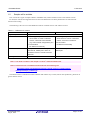


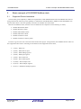
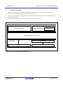
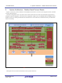


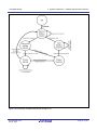


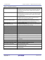


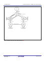


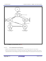


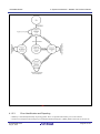


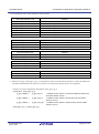


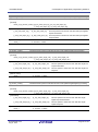


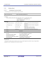
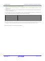


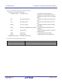

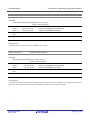


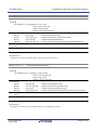

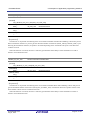


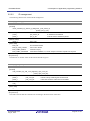


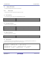
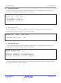


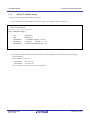


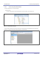

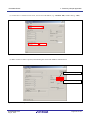

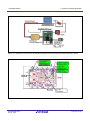


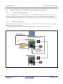

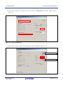


![SS400G MLSS Converter [Style:S2.2]](http://vs1.manualzilla.com/store/data/005726371_1-b873ef07ceb169a0226d293b313a67fd-150x150.png)