1
User's
Manual
4-wire ORP Metering System
Model OR400G
ORP Converter
IM 12C4C1-01E
IM 12C4C1-01E
Yokogawa Electric Corporation
3rd Edition
INTRODUCTION
The OR400G ORP Converter is used to configure the EXA OR series "4-wire ORP
Metering System." The use of this converter in combination with ORP Sensor
(OR8ERG, OR8EFG or HA485 etc.) allows continuous measurement of ORP (Oxidation
Reduction Potential) in a wide range of process. To have the converter deliver its full
capabilities, read this instruction manual.
1. Specification Check
Upon arrival of the purchased product, unpack it carefully and make sure the product is
completely free from any damage that may have occurred during transport. It is shipped
in strict conformance to the purchaser's specifications. By way of precaution, confirm
that the OR400G ORP Converter is the exact model you ordered. Also check that all
accessory components (see page 2-5) are included. When confirming the specifications,
refer to the model and suffix codes indicated on the nameplate on the instrument, For a
description of the model and suffix codes, refer to Subsection 2.2.2.
Example of Nameplate
2. Before Starting Measurement
The OR400G ORP Converter, when put into operation under the condition in which it
was delivered, operates with the parameters set upon shipment (default data). Check
whether or not the default data meet your operating conditions. Reset the parameters to
suit your operating requirements, if necessary.
To check the defaults, make use of the sheet "Worksheet for Operation Parameter
Setting" in the back of this manual.
It is advisable that, if any of the operation parameter settings have been changed, the
new data be noted in this record. When you have determined the use of the S1, S2 and
S3 contacts, attach the accessory seals in a suitable place next to the indicator lamps on
the operation panel (so the use of the contacts are clearly identified).
3rd Edition: Aug. 2007 (YK)
All Rights Reserved, Copyright © 1995, Yokogawa Electric Corporation
IM 12C4C1-01E
i
3. Information Covered in This Manual
This manual covers all of the information for handling the OR400G ORP Converter,
including instructions on installation, setting of operation parameters, inspection and
maintenance. Information necessary to better understand the product is also included.
For details on the handling of an ORP sensor used in combination with the OR400G and
the holder to install the sensor, refer to their respective, separate instruction manuals.
Note that the instruction manuals listed in the following table are for the associated
equipment used with the EXA OR series "4-wire ORP Metering System."
Manuals for Associated Equipment Used with the EXA OR series "4-wire ORP Metering System"
Model
Title of Manual
Publication No.
OR400G
ORP Convertor
OR8ERG
OR8EFG
ORP Sensor (KCI refillable tvpe)
ORP Sensor (KCI filling type)
IM 12C4C1-01E
IM 12C04K01-01E
HA485
Solid Electrolyte (Xerolite) ORP Sensor
DPA485
DPAS485
ORP Sensor (Fer Chemical Processes)
ORP Sensor (For Small Fermentation Tanks)
PH8HG
Guide Holder
PH8HF
PH8HS
Flow-through type Holder
Submersion type Holder
797M
PH8USG
Detachable Holder (for DPAS485)
Ultrasonic Oscillator
PH8PU1
OR8TBG
Cleaning Pump/Tank
Relay Terminal Box
IM 12C04J01-01E
IM 12C4Q1-02E
IM 12C4Q1-03E
IM 12C4Q1-05E
IM 12B07M02-01E
IM 12B07N01-01E
IM 12B7M1-01E
IM 12B7Q2-03E
IM 19C1B3-01E
IM 19C1E1-01E
IM 12C04W01-01E
Sys T01E.eps
[Conventions Specific to This instruction Manual]
In principle, this manual uses the following conventions to indicate specifically the
labels on the keys, the information shown on the display panel, and the labels on the
instrument.
1. Operation key
Indicated with [ ]. (Example: "
YES
key" means " [YES] key")
2. Information shown in the display section
Indicated with
[Example: On status display "
HOLD
[Example: operation key indicator "
[Example: message display
[Example: data display
" means HOLD]
YES
" means YES]
*WASH]
205(lit), 205(flashing)]
3. Labels on instrument
Indicated with <and> [Example: contact output indicator lamp
<dS3> (on
status), <sS3> (off status)
[Example: Measurement mode
<MEASURE> mode]
4. Indication of flashing in figures
Appears in a light shade of gray.
ii
IM 12C4C1-01E
After-sales Warranty
During the warranty period, for repair under warranty carry or send the product to the
local sales representative or service office. Yokogawa will replace or repair any
damaged parts and return the product to you.
Before returning a product for repair under warranty, provide us with the model
name and serial number and a description of the problem. Any diagrams or data
explaining the problem would also be appreciated.
If we replace the product with a new one, we won’t provide you with a repair report.
Yokogawa warrants the product for the period stated in the pre-purchase quotation.
Yokogawa shall conduct defined warranty service based on its standard. When the
customer site is located outside of the service area, a fee for dispatching the maintenance engineer will be charged to the customer.
In the following cases, customer will be charged repair fee regardless of warranty
period.
•
Failure of components which are out of scope of warranty stated in instruction
manual.
•
Failure caused by usage of software, hardware or auxiliary equipment, which
Yokogawa Electric did not supply.
• Failure due to improper or insufficient maintenance by user.
•
Failure due to modification, misuse or outside-of-specifications operation which
Yokogawa does not authorize.
•
Failure due to power supply (voltage, frequency) being outside specifications or
abnormal.
•
Failure caused by any usage out of scope of recommended usage.
•
Any damage from fire, earthquake, storms and floods, lightning, disturbances, riots,
warfare, radiation and other natural changes.
Yokogawa does not warrant conformance with the specific application at the user
site. Yokogawa will not bear direct/indirect responsibility for damage due to a specific
application.
Yokogawa Electric will not bear responsibility when the user configures the product
into systems or resells the product.
Maintenance service and supplying repair parts will be covered for five years after
the production ends. For repair for this product, please contact the nearest sales office
described in this instruction manual.
IM 12C4C1-01E
iii
For the safe use of this equipment
The topics and information that need your special attention in handling the product are
given in the text of this manual along with cautionary notes, such as WARNING or
CAUTION, depending on the importance of the information. For safety reasons or to
avoid possible damage to your equipment, strictly adhere to every cautionary note that
appears in this manual. For a notation, such as a warning also indicated on the product,
there is an alert mark in the manual.
(1) About This Manual
• This manual should be passed on to the end user.
• The contents of this manual are subject to change without prior notice.
• The contents of this manual shall not be reproduced or copied, in part or in whole,
without permission.
• This manual explains the functions contained in this product, but does not warrant that
they are suitable the particular purpose of the user.
• Every effort has been made to ensure accuracy in the preparation of this manual.
However, when you realize mistaken expressions or omissions, please contact the
nearest Yokogawa Electric representative or sales office.
• This manual does not cover the special specifications. This manual may be left
unchanged on any change of specification, construction or parts when the change does
not affect the functions or performance of the product.
• If the product is not used in a manner specified in this manual, the safety of this
product may be impaired.
(2) Safety and Modification Precautions
• Follow the safety precautions in this manual when using the product to ensure protection and safety of the human body, the product and the system containing the product.
(3) The following safety symbols are used on the product as well as in this manual.
DANGER
This symbol indicates that an operator must follow the instructions laid out in this
manual in order to avoid the risks, for the human body, of injury, electric shock, or
fatalities. The manual describes what special care the operator must take to avoid such
risks.
WARNING
This symbol indicates that the operator must refer to the instructions in this manual in
order to prevent the instrument (hardware) or software from being damaged, or a system
failure from occurring.
CAUTION
This symbol gives information essential for understanding the operations and functions.
Tip
This symbol gives information that complements the current topic.
SEE ALSO
This symbol identifies a source to be referred to.
iv
IM 12C4C1-01E
Table of Contents
INTRODUCTION ................................................................................................................ i
1. Specification Check .................................................................................................... i
2. Before Starting Measurement ..................................................................................... i
3. Information Covered in This Manual ....................................................................... ii
After-sales Warranty ................................................................................................ iii
For the safe use of this equipment ........................................................................... iv
1. Procedures for Key Operation .................................................................................... 1-1
1.1 Display Panel Section and Keys on Operation ...................................................
1.2 Operating the ORP Converter ..............................................................................
1.2.1 Connection of the ORP Sensor and Supply of Power ................................
1.3 Basic Key Operation ............................................................................................
1.3.1 Mode Selection at Operation Level ............................................................
1.3.2 Operation to Switch to Setting Level .........................................................
1.3.3 Operation to Enter Data (Numerical Values) .............................................
1-1
1-2
1-2
1-3
1-3
1-4
1-5
2. Overview ........................................................................................................................ 2-1
2.1 EXA OR series "4-wire ORP Metering System" ................................................ 2-1
2.1.1 ORP Sensor ................................................................................................. 2-1
2.1.2 OR400G ORP Converter ............................................................................. 2-1
2.1.3 Holders ........................................................................................................ 2-1
2.2 Specifications for OR400G ORP Converter ....................................................... 2-2
2.2.1 Standard Specifications ............................................................................... 2-2
2.2.2 Model and Codes ......................................................................................... 2-5
2.2.3 External Dimensions ................................................................................... 2-6
3. Installation and Wiring ................................................................................................ 3-1
3.1 Installation ............................................................................................................ 3-1
3.1.1 Selection of Location .................................................................................. 3-1
3.1.2 Preparation for Installation .......................................................................... 3-2
3.1.3 Converter Mounting .................................................................................... 3-3
3.2 Wiring .................................................................................................................. 3-4
3.2.1 Types of Wiring for Converter ................................................................... 3-4
3.2.2 Cable Inlet Port ........................................................................................... 3-6
3.2.3 Sensor Cable (or Dedicated Extension Cable) Connection ........................ 3-7
3.2.4 Wiring for Output Signal and Remote Cleaning Start Command ............. 3-8
3.2.5 Wiring for High/Low Alarm Contact Output ............................................. 3-9
3.2.6 Wiring for Cleaning (or Alarm ) / FAIL Contact Output ........................ 3-10
3.2.7 Wiring for Power Supply .......................................................................... 3-11
3.2.8 Ground Wiring .......................................................................................... 3-12
4. Operation .................................................................................................................... 4-1
4.1 Preparing for Operation .......................................................................................
4.1.1 Checking the Conditions in Which Converter is Installed,
Piped and Wired .........
4.1.2 Supply of Power ..........................................................................................
4.1.3 Check of Setting Parameters and Changes in Their Default Values .........
IM 12C4C1-01E
4-1
4-1
4-2
4-3
v
4.1.4 Electrode Checkup and Calibration ............................................................
4.1.5 Operation Check ..........................................................................................
4.2 Steady Operation ..................................................................................................
4.2.1 Corrective Actions Against Failure ............................................................
4.2.2 Inspection and Maintenance ........................................................................
4.3 Shutdown and Restart ..........................................................................................
4.3.1 Measures for Shutdown ...............................................................................
4.3.2 Measures for Restarting ..............................................................................
4-4
4-5
4-7
4-7
4-7
4-8
4-8
4-8
5. Parameter Setting ...................................................................................................... 5-1
5.1 Setting Operation Summary ................................................................................. 5-1
5.1.1 Operation, Setting and Service Levels ........................................................ 5-1
5.1.2 Key Operations ............................................................................................ 5-2
5.1.3 Points to be Noted in Implementing Setting .............................................. 5-3
5.2 Setting Items ........................................................................................................ 5-3
5.2.1 Setting Items at Operation Level ................................................................ 5-3
5.2.2 Items Set at Setting Level ........................................................................... 5-4
5.2.3 Items Set at Service Level .......................................................................... 5-5
5.3 Setting Procedures ............................................................................................... 5-6
5.3.1 Parameter Setting at Operation Level ......................................................... 5-7
5.3.2 Parameter Setting at Setting Level ............................................................. 5-8
5.3.3 Parameter Setting at Service Level ........................................................... 5-13
6. Electrode Checkup/Calibration Procedure ............................................................... 6-1
6.1 General .................................................................................................................
6.1.1 Electrode Checkup ......................................................................................
6.1.2 Manual Calibration ......................................................................................
6.1.3 Checkup Solution ........................................................................................
6.1.4 Errors Occurring in Calibration ..................................................................
6.2 Electrode Checkup/Manual Calibration (Emf Correction) Procedure ................
6.2.1 Preparation ...................................................................................................
6.2.2 Electrode Checkup Operation .....................................................................
6.2.3 Manual Calibration (Emf Correction) .........................................................
6.3 Manual Calibration (Tune-in) Procedure ............................................................
6.3.1 Preparation ...................................................................................................
6.3.2 Manual Calibration (Tune-in) .....................................................................
6-1
6-1
6-1
6-1
6-1
6-2
6-2
6-3
6-3
6-4
6-4
6-4
7. Inspection and Maintenance ..................................................................................... 7-1
7.1 Regarding Overall 4-wire ORP Metering System ..............................................
7.1.1 lnspection and Maintenance to be Implemented Periodically ....................
7.1.2 Inspection and Maintenance to be Implemented on Occasion ...................
7.2 Inspection and Maintenance Procedure for OR400G ORP Converter ...............
7.2.1 Wiping off Front Cover (Window) .............................................................
7.2.2 Inspection of Degree of Dryness Within the Converter .............................
7.2.3 Replacement of Fuse ...................................................................................
7-1
7-1
7-1
7-2
7-2
7-2
7-2
8. Troubleshooting .......................................................................................................... 8-1
8.1 Corrective Actions in Case of a Converter Malfunction ....................................
8.1.1 Case Where ORP Converter Fails to Function ...........................................
8.1.2 Case Where Problems are Found with Operation Keys or Displays .........
8.2 Corrective Actions in Case of Failure (Error) Detection ....................................
vi
8-1
8-1
8-1
8-2
IM 12C4C1-01E
8.3 Corrective Actions in the Case of a Measurement Failure ................................. 8-3
Worksheet for Operation Parameter Setting ............................................................. i
Customer Maintenance Parts List .................................................CMPL 12C04C01-01E
Revision Record .................................................................................................................... i
IM 12C4C1-01E
vii
1. Procedures for Key Operation
1. Procedures for Key Operation
This chapter introduces the basic patterns of key operation fer the OR400G ORP
Converter. These key operations are introduced to demonstrate how to use the keys and
how to check the performance of the instrument before installation. For key operations
used to check or change preset parameter settings, see Chapter 5.
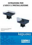
1.1 Display Panel Section and Keys on Operation
Figure 1.1 shows the operation panel of the OR400G ORP Converter. There are operation keys and a display section on the panel. The six keys that can be seen through the
front cover can be operated from the outside.
The broken line indicates the area thet can
be viewed through the front cover
Liquid crystal
display (LCD)
Status display
FAIL
HOLD
Operation modes
Setting / Service levels
MODE
Data Display
mV
MEASURE
Pointer display
MAN. CAL
DISPLAY
YES NO
Message display
ENT
HOLD
SETPOINTS
RANGE
SET HOLD
WASH DATA
SERVICE
Key operation display
YES
NO
MODE
ENT
CONTACTS
S1
S2
S3
Setting level selector key
FAIL
Lamps indicating output
of contact signals
>
Operation keys
: Press to answer "Yes" to the given message in conjuction
[YES]
with the flashing key operation display.
: Press to answer "Yes" to the given message in conjuction
[NO]
with the flashing key operation display.
[MODE] : Press to change from the measurement mode to the operation
level. Also press this key to return to the measurement mode
from other mode.
: Press to select a digit in data setting.
[>]
: Press to select a numeral in data setting.
[ ]
: Press to enter a keyed-in data item.
[ENT]
F1.1E.eps
Figure 1.1 Operation Panel
IM 12C4C1-01E
1-1
1. Procedures for Key Operation
1.2 Operating the ORP Converter
1.2.1 Connection of the ORP Sensor and Supply of Power
The OR400G ORP Converter operates on an AC power supply at the specified voltage.
Before turning on the power, connect the ORP sensor. The ORP sensor can be connected with the membrane protective covering (for storage) left on.
WARNING
The converter has no power switch. In order to avoid electrical shock or damage to
the instrument, properly wire the sensor to the predetermined external wiring terminals of the converter before turning on the power.
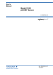
Carry out wiring after removing both the front and terminal covers, as shown in Figure
1.2.
Figure 1.2 External Wiring Terminals
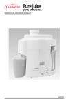
When turned on, the converter starts in the measurement mode; the data display
indicates an ORP value and the message display, the current of an output signal.
(initial status)
If the converter detects a failure, FAIL appears, the <FAIL> indicator lamp lights
up, and the message display indicates an error code. Should a failure occur, go to
Chapter 8.
MODE
mV
YES
MEASURE
NO
MODE
ENT
FAIL
mV
MEASURE
MAN. CAL
DISPLAY
MAN. CAL
DISPLAY
HOLD
HOLD
CONTACTS
S1
S2
S3
YES
NO
MODE
ENT
FAIL
Normal Display
MODE
CONTACTS
S1
S2
S3
FAIL
Display When a Failure Occurs
Figure 1.3 Example of Display in Measurement Mode
1-2
IM 12C4C1-01E
F1.3E.eps
1. Procedures for Key Operation
1.3 Basic Key Operation
1.3.1 Mode Selection at Operation Level
SEE ALSO
For more information, see Section 5.3.
To check that key operation from the outside can be done normally, attach the front
cover. in selecting a mode, note the following two points:
Pressing the [MODE] key in modes other than the measurement mode returns to the
measurement mode. However, pressing the key while the output signal hold is active
goes to the <HOLD> mode.
If no key is operated for ten minutes, the converter returns to the measurement mode.
(Default setting).
1. Press the [MODE] key once. The display shown in Figure 1.4 (1) appears.
(1)
(2)
MODE
MEASURE
YES NO
MAN. CAL
DISPLAY
HOLD
MODE
mV
MEASURE
YES NO
MAN. CAL
DISPLAY
HOLD
F1.4E.eps
The pointer indicating <MAN.CAL> and
YES and NO in the key operation sisplay
are flashing.
This indication means, "Do you want to do
a manual calibration? Please answer by
pressing the [YES] or [NO] key."
This is the display when the [YES] key is
pressed in answer to the indication in (1).
As soon as the pointer stops flashing, the
message display changes to START,
indicating that the cover has entered
the manual calibration mode.
Figure 1.4 Examples of Indication at Operation Level
2. Press the [NO] key for the display in Figure 1.4 (1). Each time you press the [NO]
key, the display changes. After you have cycled through a round with this key
operation, the converter returns to the display shown in Figure 1.4 (1).
IM 12C4C1-01E
1-3
1. Procedures for Key Operation
1.3.2 Operation to Switch to Setting Level
SEE ALSO
For more information, see Section 5.3.
To switch to the setting level, remove the front cover. In the measurement mode, press
the [*] key (setting level selection).
(1)
(2)
MODE
MODE
MEASURE
MEASURE
YES NO
MAN. CAL
DISPLAY
HOLD
SETPOINTS
RANGE
SET HOLD
WASH DATA
SERVICE
YES NO
MAN. CAL
DISPLAY
HOLD
SETPOINTS
RANGE
SET HOLD
WASH DATA
SERVICE
This symbol appears when the
converter is at the setting or
service level.
When you press the [*] key, a display appears,
meaning "Do you want to change to the alarm
point setting mode? Please answer by pressing
the [YES] or [NO] key."
If you press the [YES] key in Figure 1.5(1), the
converter enters the alarm point setting mode.
At the same time, a display appears, meaning
"Do you want to view the setting of contact
output S1?"
F1.5E.eps
Figure 1.5 Examples of Display at Setting Level
1-4
IM 12C4C1-01E
1. Procedures for Key Operation
1.3.3 Operation to Enter Data (Numerical Values)
CAUTION
Entered data are not canceled even when the power is turned off. If you have made a
temporary change in the data, enter the normal fixed data again.
If you press the [YES] key for the display in Figure 1.5 (2), the converter switches to
the display shown in Figure 1.6 (1), The following procedure is for a case where you
change the data value "-1000 (mV)" set in that display to "-500 (mV)."
(1) Press the [ ] key once to change the flashing "-1" to a minus sign (-) only.
(2) Press the [>] key once to have "0" in the hundreds place begin flashing.
(3) Enter "5" with the [ ] key. `
(4) Press the [ENT] key. This enters the value "-500," and the converter then returns to
the display shown in Figure 1.5 (1).
^
^
(1)
(2)
MODE
MODE
mV
mV
MEASURE
MAN. CAL
DISPLAY
ENT
HOLD
SETPOINTS
RANGE
SET HOLD
WASH DATA
SERVICE
Pressing the [YES] key in Figure 1.5(2) changes
the display to look like this.
MEASURE
MAN. CAL
DISPLAY
ENT
HOLD
SETPOINTS
RANGE
SET HOLD
WASH DATA
SERVICE
Pressing the [ENT] key enters the displayed value.
F1.6E.eps
Figure 1.6 Examples of Display During Data Setting
IM 12C4C1-01E
1-5
2. Overview
2. Overview
This chapter gives an overview of the EXA OR series "4-wire ORP Metering System"
and the specifications for the OR400G ORP Converter.
2.1 EXA OR series "4-wire ORP Metering System"
2.1.1 ORP Sensor
The ORP sensor detects a potential generated by the oxidation-reduction reaction of a
solution. ORP sensors include OR8EFG and OR8ERG sensors suited for a regular
process, and HA485, DPA485 and DPAS485 sensors used for a special process.
2.1.2 OR400G ORP Converter
The OR400G ORP Converter A-to-D converts the oxidation-reduction potential
received from an ORP sensor to indicate it in digital form. It outputs the potential as an
analog signal of 4 to 20 mA DC. The converter is provided with a variety of operation
parameter setting functions necessary to measure and control an oxidation-reduction
potential as well as selfdiagnostic functions.
2.1.3 Holders
Equipment configuring the ORP Metering System includes holders to
support the ORP sensor and a relay terminal box (with a dedicated
extension cable) used if the sensor is located away from the converter.
There are three types of holders: a guide holder, flow-through type
holder, and submersion type holder. These are selected depending on the
measurement conditions. The flow-through type and submersion type
holders are available in versions having cleaners (jet, brush or ultrasonic)
that remove dirt from the sensor's membrane.
IM 12C4C1-01E
2-1
2. Overview
2.2 Specifications for OR400G ORP Converter
The OR400G ORP Converter delivers an analog signal relative to an oxidation-reduction
potential and many different contact signals such as upper/lower-limit alarms. Provided
with many operation parameter setting functions, the converter lends itself to a wide
variety of applications. It also has several self-diagnostic functions which simplify
maintenance work.
2.2.1 Standard Specifications
Measurement:
Oxidation-reduction potential (ORP) of a solution
Measuring range:
-1500 to +1500 mV
Display:
digital (LCD), range -1500 to +1500 mV
Converter output:
4 to 20 mA DC, isolated (floating), maximum load resistance 600V.
Converter range:
output may be set to correspond to an arbitrary input span of at least 100 mV. (Shipping-time default is for output to correspond to -1500 to +1500 mV measuring range).
Contact output:
Contact output function that can be set
Contact
S1
Function
Setting (freely selectable)
Operation (freely selectable)
OFF, Low limit, High limit,
ON/OFF
HOLD
OFF, Low limit, High limit,
S2
Ditto
HOLD
OFF, Low limit, High limit,
S3
Ditto
HOLD, Cleaning timer,
Hi-Hi limit, Lo-Lo limit
FAIL
Failure
ON/OFF
T02C.EPS
Contact ON/OFF
(a) S1, S2, S3
(b) FAIL
Power
ON
Action
ON Closed
OFF Open
Power
OFF
Open
ON
Action
ON
Closed
OFF
Closed
OFF Open
T02D.EPS
When closed, each indicator lamp is lit corresponding to each contact status.
Contact type : Relay contact output *dry contact
Contact rating:
250 V AC, 2 A, Max. 100 VA
220 V AC, 2 A, Max. 50 W
Contact input:
Supports manual starting of auto-wash functions.
Power supply voltage:
88 to 132V AC or 176 to 264V AC at 50/60Hz.
2-2
IM 12C4C1-01E
2. Overview
Power consumption:
approx. 8.5VA
Operating temperature:
-10 to 55 C
Operating humidity:
10 to 90 % RH
Storage temperature:
-30 to70 C
Construction:
Watertight complying with JIS C0920, equivalent to NEMA 4 water proof construction
Materials:
Case: Aluminum alloy casting
Cover and Window: Polycarbonate
Finish:
Baked polyurethane resin finish
Color:
Cover: Deep sea moss green (Munsell 0.6GY3.1/2.0 equivalent.)
Case: Frosty white (Munsell 2.5Y8.4/1.2 equivalent.)
Mounting:
50A dia. vertical or horizontal pipe, wall, rack or panel.
Condition of Installation
Installation is possible inside or outside Concerning its condition, see chap 3.1.
Electrical connections:
ORP sensor: 13.5mm dia. hole (plastic gland, watertight to JIS A8 equivalent.) Power,
contacts, and output: 21mm dia., use cable of 9 to 12 mm dia. (plastic gland, watertight
to JIS A15 equivalent.)
Weight:
Body: Approx. 2.5 kg
Mounting bracket: Approx. 0.5 kg
Dimensions:
144 x 144 x 135 mm
Standard Performance
Repeatability:
0.5% of input span (not including sensor)
Linearity:
0.5% of input span (not including sensor)
IM 12C4C1-01E
2-3
2. Overview
Operating Functions
Display:
3-1/2 digital display (data display)
Six digit alphanumerics (message or data display)
Display items:
ORP value (mV)
mA output
Zero-shift value
Interactive prompts
Key entry request (for hold value)
Error display (if error occurs)
Fail display (if failure occurs)
Operation-mode actions:
Message area display content selection
Set / release output hold setting
Manual calibration (one-point)
Maintenance-mode actions:
Setting of alarms S1, S2 and S3
Setting of output ranges
Setting of hold parameters
Enable/disable hold
Hold last value / Hold preset value setting
Setting of preset value
Setting of wash parameters
Selection of auto/manual wash
Manual wash start/stop
Auto wash enable/disable
Wash cycle interval: settable 0.1 to 36 hours
Settling time: settable 0.1 to 10 min.
Wash cycle duration: settable 0.1 to 10 min.
Service-mode actions:
Zero point check
Settling (to 50%) time check On / Off
Settling (to 50%) time setting (0.1 to 10 min.)
Burnout (upscale/downscale/Off)
Mode auto revert On / Off
Converter mA output On / Off
Error reset
2-4
IM 12C4C1-01E
2. Overview
Items detected by self-diagnostics:
ORP measurement value abnormal
Zero point shift abnormal
Settling time abnormal
EEPROM abnormal
2.2.2 Model and Codes
Option
Code
Suffix Code
Model
Specifications
OR400G
4-wire ORP Converter
Power supply
voltage
Language for
warning, etc.
100/110 V AC, 50/60 Hz
200/220 V AC, 50/60 Hz
-1
-2
Japanese
English
-J
-E
-A
Option
Always -A
Mounting hardware
/U
/PM
/H3
/H4
/X1
/SCT
/AFTB
/ANSI
Hood
Tag plate
Conduit Adapter
Pipe mounting bracket
Panel mounting bracket
Awning hood (carbon steel)
Awning hood (stainlss steel)
Epoxy-baked finish
with stainless tag plate
G1/2
1/2NPT
T14.EPS
Accessories
Item
Label for contact signals
Spare fuse
Pipe/wall mounting bracket
Panel mounting bracket
Shading hood
Shading hood
Tag plate
Adapter for conduit connection
Part Number
K9313PC
K9313PS
K9171SS
K9171ST
K9664CA
K9664CC
Y9412NP
K9313PN
Remarks
For display on the operation panel
0.1 A (for either a 100V or 200V power line)
Attached when option code "/U" is specified
Attached when option code "/PM" is specified
Attached when option code "/H3" is specified
Attached when option code "/H4" is specified
Attached when option code "/SCT" is specified
Attached when option code "/AFTG" is specified
T2.5E.eps
IM 12C4C1-01E
2-5
2. Overview
2.2.3 External Dimensions
Unit: mm
Hood (optional)
Option code : /Hh
Four M6 screws, 8 deep
184
220
80
72
20
144
80
112
23
144
Cable inlet port (13.5 dia. holes)
For JIS A8 cable gland
36
Cable inlet port (21 dia. holes)
equivalent to JIS A15 cable gland
A
B
36
C
D
36
36
E
A:
B:
C:
D:
E:
For output signal / contact input
For sensor cable
For power supply
For contact output (S1 and S2)
For contact output (S3 and FAIL)
38
F2.3E.eps
Ground terminal
(M4 screw)
Adapter for conduit work (option code:/AFTG, /ANSI)
Adaptor
G 1/2 female ( / AFTG)
1/2 NPT female ( / ANSI)
2-6
49
Approx. 55
Unit : mm
F2.4E.eps
IM 12C4C1-01E
2. Overview
Pipe Mounting Bracket/Wall Mounting Bracket (option code:/U)
Example of bracket used for pipe mounting
188
Unit : mm
M6, 4 screws
174
200
50
Nominal 50 A (O.D 60.5mm)
mounting pipe
100
Example of bracket used for wall mounting
135
13
M6, 4 screws
224
200
35
15
70
10mm dia., 3 holes
100
F2.5E.eps
Mounting Bracket (option code:/PM)
23
12 max.(panel thickness)
Unit :mm
M6, 4 screws
137 +20
100
137 +20
178
Panel cutout dimensions
F2.6E.eps
IM 12C4C1-01E
2-7
3. Installation and Wiring
3. Installation and Wiring
The OR400G ORP Converter must be installed in a location where the operator can
view the display normally and operate keys properly. This chapter explains how to select
such a location and install and wire the converter.
3.1 Installation
3.1.1 Selection of Location
The OR400G ORP Converter can be installed both inside and outside.
Install the OR400G where the following conditions are met.
Near the ORP sensor
Consider the cable length of the sensor the converter is to be combined with (including
a dedicated extension cable). Even if relay terminal boxes are used, it is recommended
that the total length of the sensor cable and the extension cable be within 25 m.
No presence of corrosive gases
Corrosive gases are not desirable because they may damage the electrical components
in the converter.
Little mechanical vibration
Vibration may loosen the connections of the external wiring.
Normal temperatures with only small fluctuations
It is necessary for the temperature not to exceed the range of -10 to 55 C.
Humidity maintained between 10 to 90% RH
Avoid choosing a location likely to be exposed to abnormally high or low humidity
over a prolonged period. It is recommended that the converter be used at a humidity
between 25 to 85 % RH.
No exposure to direct sunlight
Direct sunlight may raise the temperature in the converter to abnormal levels. If direct
sunlight cannot be avoided, use a hood for shading (optional).
IM 12C4C1-01E
3-1
3. Installation and Wiring
3.1.2 Preparation for Installation
3.1.2.1 Assembly of Separate Attachments
Parts specified with the option codes (hood, mounting bracket, adapter for conduit
connection, etc.) are delivered as separate attachments. To avoid losing these parts, it is
recommended that you attach them to the converter before installation. (For details on
assembly, see Subsections 2.2.3 and 3.1.3.)
3.1.2.2 Installation Provisions
Make provisions to install the OR400G ORP Converter in a position for easy operation.
(1) Pipe mounting
The OR400G converter is fixed to a stanchion (pipe) with a U-bolt. Install a rigid pipe
with an OD of 60.5 mm in an upright position (a horizontal position is also acceptable).
(2) Wall mounting
Fix the OR400G converter with three M8 bolts (not supplied). Drill the mounting
surface of the wall, as shown in Figure 3.1.
Unit: mm
144
102
35
Center of the OR400G
70
Three M8 screw-holes,
or three 10-dia. through-holes
F3.1E.eps
Figure 3.1 Drilling for Wall Mounting
(3) Panel mounting
Provide a cutout on the panel, as shown in Figure 3.2.
178
Unit: mm
Width of the mounting bracket
137
+2
0
137 +20
F3.2E.eps
Figure 3.2 Cutout for Panel Mounting
3-2
IM 12C4C1-01E
3. Installation and Wiring
3.1.3 Converter Mounting
(1) Pipe mounting
Figure 3.3 shows the pipe mounting bracket and the mounting procedure.
Bracket mounting screws
Note : If a hood (see 2.2.3) is to be
attaehed, fix it making use of the
two upper bracket mounting screws.
Converter
Bracket
Pipe mounting bracket
Nut(2 pcs)
U-bolt
Washers(2 pcs)
F3.3E.eps
Stanchion (60.5 mm pipe)
Figure 3.3 Pipe Mounting Procedure
(2) Wall mounting
Figure 3.4 illustrates the wall mounting procedure.
Converter
Mounting hole (3 places)
M8 bolts (not supplied)
Provide bolts of a length suitable
for the mounting holes.
Pipe mounting bracket
is attached. Only
bracket is used when
wall mounting.
Bracket
F3.4E.eps
Figure 3.4 Wall Mounting Procedure
(3) Panel mounting
Figure 3.5 illustrates the panel mounting procedure.
Panel
Converter
Bracket
Mount the OR400G after inserting it
into the panel cut opening before
attaching the bracket.
Fixing screws (2 pcs)
F3.5E.eps
Figure 3.5 Panel Mounting Procedure
IM 12C4C1-01E
3-3
3. Installation and Wiring
3.2 Wiring
3.2.1 Types of Wiring for Converter
Provide the following types of wiring on the OR400G ORP Converter. However, do not
wire for unused functions.
(1) Sensor cable (or extension cable) connection (see Subsection 3.2.3)
(2) Wiring for output signal and for remote cleaning start command (contact input) (see
Subsection 3.2.4)
(3) Wiring for high and low alarms ( S1 and S2 contact outputs) (see Subsection 3.2.5)
(4) Wiring for cleaning (or alarm) ( S3 contact output ) failure (FAIL contact output)
(see Subsection 3.2.6)
(5) Wiring for power supply (see Subsection 3.2.7)
(6) Ground wiring (see Subsection 3.2.8)
Operation panel
Sensor cable / output signal wiring
connection terminal
Pull on the knob at the
lower right of the front
panel to open the panel
Contact output / power cord terminal
Terminal cover
HIGH VOLTAGE Warning
Be careful not to touch
the terminals while power
is being supplied
Grounding terminal (M4 screw)
Located on the left side of the case.
F3.6E.eps
Figure 3.6 Position of terminal blocks for external wiring cable connection
3-4
IM 12C4C1-01E
3. Installation and Wiring
Wiring
OR400G
Output signal
(4 to 20mA DC)
mA
Power supply
L2
Contact input
(cleaning start
command)
S1
Contact
output S1
S2
Contact
output S2
S3
Contact output S3 (cleaning
or high and low alarms)
FAIL
Contact output FAIL (failure)
R1
R2
RE
Sensor cable
or dedicated
extension cable
L1
SE
GE
G
RE
High and low
alarms
SE
GE
G
Grounding terminal (M4 screw)
Grounding (100 or less)
Note : External wiring connection terminal size is for M3 screw.
F3.7E.eps
Figure 3.7 External Wiring Cable Connection Terminals and Hookup
IM 12C4C1-01E
3-5
3. Installation and Wiring
3.2.2 Cable Inlet Port
There are four cable inlets on the OR400G ORP Converter in addition to the one for a
sensor cable. These inlets have cable glands for a cable with an OD of 9 to 12 mm.
Introduce cables through their respective inlets shown in Figure 3.8. If there is any cable
inlet not used, seal the opening so that no dust gets in.
Cable inlet port (13.5 dia. holes)
For JIS A8 cable gland
36
Cable inlet port (21 dia. holes)
equivalent to JIS A15 cable gland
A
B
36
C
D
36
36
E
A:
B:
C:
D:
E:
For output signal / contact input
For sensor cable
For power supply
For contact output (S1 and S2)
For contact output (S3 and FAIL)
38
Ground terminal
(M4 screw)
F3.8E.eps
Figure 3.8 Use of Each Cable Inlet
When protecting a cable with a conduit, use an adapter (4 sets are supplied when the
option code "/AFTG" is specified). Remove the glands from the A, C, D, and E cable
inlets and attach the supplied adapters in place of the above glands, as shown in Figure
3.9. No conduit installation is required for sensor cable inlet B. Use the gland that is
already assembled to the sensor cable.
CAUTION
Be sure to use an OR8TBG Relay Terminal Box if it is necessary to protect all the
wiring cables to the converter with conduits. The cable between the relay terminal box
and the converter (dedicated extension cable) can be protected with a conduit. An
adapter for that purpose can be supplied attached to the relay terminal box (specify
accordingly).
Adaptor
49
G 1/2 female ( / AFTG)
1/2 NPT female ( / ANSI)
Approx. 55
Unit : mm
F3.9E.eps
Figure 3.9 Conduit Connecting Adapter
3-6
IM 12C4C1-01E
3. Installation and Wiring
3.2.3 Sensor Cable (or Dedicated Extension Cable) Connection
Normally, the sensor cable is connected directly to the converter. If an OR8TBG Relay
Terminal Box is used, first connect the sensor cable to the box. Then, connect the box
with the converter using the dedicated extension cable (supplied with the OR8TBG
Relay Terminal Box). The sensor cable and the dedicated extension cable already have a
finished end treatment.
CAUTION
The end treatment of a dedicated extension cable may differ between the connection
with the relay terminal box and the connection with the converter. When using a
dedicated extension cable, examine both ends before wiring the cable.
3.2.3.1 Connection Procedure
(1) Connect each conductor of the sensor cable to the predetermined terminals of RE,
SE, GE and G.
CAUTION
Some types of sensors use a cable lacking the G leadwire. These sensors have two SE
leadwires. Connect both of them to terminal SE. When introducing the sensor cable
into the converter, remove the nut from the sensor cable gland.
(2) Fix the cable gland.
Insert the cable gland into the inlet and tighten the nut.
IM 12C4C1-01E
3-7
3. Installation and Wiring
3.2.4 Wiring for Output Signal and Remote Cleaning Start Command
This is wiring for transmitting the converter's output signal to a receiving instrument,
such as a recorder, and for sending a contact input signal to the converter to start
cleaning. The output signal is a unified 4 to 20 mA DC signal corresponding to any
preset range. The wiring for the contact input signal is necessary only when you use a
remote cleaning start command in an application where the holder with a cleaner is used.
The on/off contact input can be identified with input resistances (on: 10 or less for
more than 0.25 second; off: 100 k or more). Use a dry contact.
3.2.4.1 Cable to Be Used
Use a shielded cable with a finished OD of 9 to 12 mm. Select either a 2 or 4 conductor
cable depending on the number of signals.
3.2.4.2 Connection Procedure
(1) End-treat the cable.
Strip off about 40 mm of the cable insulation covering from the cable end. Cut the
exposed shield at its root near the remaining covering and solder a grounding
leadwire (about the same length as the cable conductors) to the shield. Protect the
soldered point by wrapping it with insulation tape, for example. Next, attach
crimping terminal lugs conforming to an M3 screw to the tips of the leadwire and
each cable conductor.
(2) Connect each cable conductor to the specified terminals.
Plus (+) and minus (-) terminals
:conductors for 4 to 20 mA DC output signal
Grounding ( ) terminal
:conductor grounding
R1 and R2 terminals
:conductors for contact input signal
CAUTION
Ground the cable shield only at the OR400G ORP Converter.
When introducing the cable into the converter, remove the parts assembled to the
cable gland located at cable inlet A and pass the cable through these parts in the
proper sequence in advance.
(3) Fix the cable.
Adjust the length of the portion of the cable housed within the converter and fix the
cable by reassembling the parts through which the cable passes to the cable gland.
3-8
IM 12C4C1-01E
3. Installation and Wiring
3.2.5 Wiring for High/Low Alarm Contact Output
This is the wiring provided to output high and low alarms as contact signals S1 and S2.
This wiring can also be used to know that the output signal hold is "on" at the operation
level. The ratings of these relay contacts (normally on) for contact signal outputs are
summarized in Table 3.1.
CAUTION
Contact outputs S1 and S2 must be "open" when deenergized.
Table 3.1 Ratings of Relay Contacts for Contact Outputs
DC
Maximum alIowable voltage
Maximum allowable current
Maximum allowable power
220V
2A
50W
AC
250V
2A
100VA
T3.1E.eps
3.2.5.1 Cable to Be Used
Use a cable with a finished OD of 9 to 12 mm. Select either a 2 or 4 conductor cable
depending on the number of signals.
3.2.5.2 Connecting Procedure
(1) End-treat the cable.
Strip off about 40 mm of the insulation from the cable end and attach crimping
terminal lugs conforming to an M3 screw to the tip of each conductor.
(2) Connect each cable conductor to the specified terminals.
Terminals S1 (two): conductors for contact output S1
Terminals S2 (two): conductors for contact output S2
When introducing the cable into the converter, first remove the parts attached to the
cable gland located at cable inlet D and pass the cable through these parts in the
proper sequence in advance.
(3) Fix the cable.
Adjust the length of the portion of the cable housed within the converter and fix the
cable by reassembling the parts through which the cable passes to the cable gland.
IM 12C4C1-01E
3-9
3. Installation and Wiring
3.2.6 Wiring for Cleaning (or Alarm ) / FAIL Contact Output
In an application where a holder with a cleaner is used, the cleaning signal is delivered
from the S3 contact output. In other applications, the S3 contact output can be used for
the high (or low) alarm. From the FAIL contact output, a failure signal is output if the
converter detects a failure. This wiring is done if these contact signals are used.
The ratings of the relay contacts ( normally open) for contact signal outputs are the same
as those of contact S1 or S2 shown in Table 3.1. When connecting equipment to these
contact outputs, make sure that the equipment satisfies the ratings.
CAUTION
Contact S3 is "open" at power off, while the FAIL contact output is "closed."
3.2.6.1 Cable to Be Used
Use a cable with a finished OD of 9 to 12 mm. Select a 2 or 4 conductor cable depending on the number of signals applied.
3.2.6.2 Connecting Procedure
(1) End-treat the cable.
Strip off about 40 mm of the insulation from the cable end and attach crimping
terminal lugs conforming to an M3 screw to the tip of each conductor.
(2) Connect each cable conductor to the specified terminals.
S3 terminals (two) :
conductors for contact output S3
FAIL terminals (two) :
conductors for contact output FAIL
When introducing the cable into the converter, remove the parts attached to the
cable gland located at cable inlet E and pass the cable through these parts in the
proper sequence in advance.
(3) Fix the cable.
Adjust the length of the portion of the cable housed within the converter and fix the
cable by reassembling the parts through which the cable passes to the cable gland.
3-10
IM 12C4C1-01E
3. Installation and Wiring
3.2.7 Wiring for Power Supply
Supply AC power of the specified voltage (88 to 132 V or 176 to 264 V) and frequency
(50 / 60 Hz) to the OR400G ORP Converter.
CAUTION
The OR400G ORP Converter has no power switch. Be sure to provide a double-pole
switch in the power line. Use a power outlet free from any variation that may cause the
voltage to exceed the tolerable voltage range.
3.2.7.1 Cable to Be Used
Use a two conductor cable with a finished OD of 9 to 12mm.
3.2.7.2 Connecting Procedure
(1) End-treat the cable.
Strip off about 40 mm of the insulation from the cable end and attach crimping
terminal lugs conforming to an M3 screw to the tip of each conductor.
(2) Connect each cable conductor to terminals 1 and 2.
When introducing the cable into the converter, remove the parts attached to the
cable gland located at cable inlet C and pass the cable through these parts in the
proper sequence in advance.
(3) Fix the cable.
Adjust the length of the portion of the cable housed within the converter and fix the
cable by reassembling the parts through which the cable passes to the cable gland.
After connection to the external wiring terminals described in Subsections 3.2.1 to
3.2.7 is completed, mount the terminal cover.
IM 12C4C1-01E
3-11
3. Installation and Wiring
3.2.8 Ground Wiring
The grounding terminal is located on the left side of the case, as shown in Figure 3.10.
Ground the terminal using a wire having a nominal cress section of 2 mm2 or more,
complying with JIS class 3 grounding (the ground resistance must be 100 or less).
The terminal screw is M4-threaded. Attach a crimping terminal lug matching the M4
screw to the tip of the wire.
Washer
Grounding terminal screw (M4)
Grounding wire (nominal cross section of
2 mm2 or more)
F3.10E.eps
Figure 3.10 Grounding Terminal
CAUTION
If grounding is not possible from the converter case, ground the converter at the power
supply using the power cable conductor. In this case, use a three-conductor cable or a
two conductor shielded cable for power-supply wiring and connect the grounding
conductor to terminal
(for grounding) in the converter.
3-12
IM 12C4C1-01E
4. Operation
4.
Operation
This chapter describes the operation of the ORP Metering System by mainly referring to
the operating procedures for the OR400G ORP Converter.
4.1 Preparing for Operation
Ready for operation all equipment composing the ORP Metering System. For details on
equipment other than the ORP converter, see their respective separate instruction
manuals.
4.1.1 Checking the Conditions in Which Converter is Installed, Piped and Wired
Inspection of Installation
(1) Check that the ORP sensor is ready for measurement (see the appropriate instruction
manual) and the holder is securely fixed.
lnspection of Wiring
(1) Check that all necessary wiring has been completed and the cables are properly
connected. After checking the connection to the ORP converter, be sure to mount the
terminal cover.
(2) Check that alI unused cable inlets are plugged with a blind.
Inspection of Piping
The types of piping include sampling piping (when a flow-through type holder is used)
and cleaning utility piping (when a holder with a jet or brush cleaner is used). In some
applications where an OR8EFG ORP Sensor is used, an air pipe for pressurizing the KCl
reservoir tank may be installed. Likewise, in some applications where a 797M Detachable Holder is used, a steam pipe for sterilization may be installed.
(1) Check that all necessary piping has been completed.
(2) If a flow-through type holder is used, check that the specifications of the pipe
(material, diameter, etc.) conform to the requirements of the measured solution that
flows through the pipe (flow rate, pressure, temperature, etc.).
(3) lf a holder with a jet or brush cleaner is used, check that piping is provided that
supplies the cleaning utility (water and air) at a specified pressure.
IM 12C4C1-01E
4-1
4. Operation
4.1.2 Supply of Power
First, confirm that connected control equipment is not being operated from a signal
from the ORP converter. Then, turn on the switch provided on the power line to bring
the converter into operation. Turning on the power causes the converter to start operating in the measurement mode.
Main Actions in Measurement Mode (depend on the parameters set upon shipment from the factory)]
(1) The measured ORP value (mV) appears in the data display and the output current of
the signal (mA) in the message display.
(2) Output signals of 4 to 20 mA DC corresponding to the measurable range (-1500 to
1500 mV) are sent out.
(3) lf the ORP converter detects a failure, it delivers the FAIL contact output (contact is
"closed").
Tip
The FAIL contact is also "closed" during power off.
lf a failure is detected, the output signal is held at the value immediately before.
4-2
IM 12C4C1-01E
4. Operation
4.1.3 Check of Setting Parameters and Changes in Their Default Values
Set up relevant parameters to meet individual operating requirements. In the case of critical
parameters, confirm that they are given correct settings even if the values set upon shipment from the factory (default values) are to apply without change.
CAUTION
If a holder with a cleaner is used, re-set the cleaning timer at "Execute." lf
default values have been changed, it is convenient to record the data in the
"Notes on Operation Parameter Settings," for example, attached at the end of
this manual.
The types and functions of setting parameters are detailed in Chapter 5. Refer to this
information before you start setting parameters. For reference, the pages describing the
main setting parameters and key operations are shown below.
[Key Operation Procedures]
Basic patterns of key operation .................................................................... (page 1-3)
Switching from measurement mode to setting level ...................... (page 1-4)
Selecting numeric values and digits (data entry) .......................... (page 1-5)
Aborting setting operation (returning to measurement mode) ....... (page 5-2)
Moving through setting items en the setting level. ..................................... (page 5-6)
Selecting setting parameters on the service level. ..................................... (page 5-13)
[Output Signal]
Changing the measuring range ..................................................................... (page 5-9)
Holding the output signal (during calibration, cleaning or maintenance) .(page 5-10)
Output signal "Burn-up/burn-down" (at occurrence of FAIL signal)...... . (page 5-14)
Shutting down transmission of output signals ............... ........................... (page 5-15)
[Contact Output]
Execution of automatic cleaning ................................................................ (page 5-11)
Providing alarm setpoints .................................................. (pages 5-8, 5-16 and 5-17)
Setting delay time and hysteresis ............................................................... (page 5-18)
[Specifications of Combined ORP Sensor]
Entering types of reactive elements (metal = platinum/gold, antimony) .. (page 5-20)
IM 12C4C1-01E
4-3
4. Operation
4.1.4 Electrode Checkup and Calibration
Using a checkup solution, check the electrode to ensure that the ORP sensor is normal.
Tip
Electrode Checkup and Calibration
Normally, an ORP meter is used for the purpose of, for example, knowing the end of a
reaction in a process where absolute values are not a concern. In such an application,
there is no problem in using the ORP meter even if there is a slight difference between
the reading given by the electrode and the true ORP value. However, dirt accumulating
on the wetted part or reactive element not only affects the emf of the electrode adversely
but also causes other problems, such as the degradation of responses. It is, therefore,
advisable that the electrode be cleaned at regular intervals so it is maintained in excellent condition.Electrode checkup (examination of the emf is carried out to determine
whether the electrode is in need of maintenance (cleaning of the wetted part or reactive
element) or not. Calibration, on the other hand, is carried out to correct the output value
for a case where, because of a degraded electrode, the emf slightly exceeds the tolerable
limit even after maintenance.
Note: If the emf largely exceeds the tolerable limit, the electrode may have reached
the end of its service life. An electrode failure is suggested by the indication of
error code E2 on the display (if CODE 03 of the service level is applied to turn
on the checking for asymmetric potential).
Calibration is also carried out to tune the measured value of this system to that of
another system.
4.1.4.1 Reagent and Apparatus Arrangements
When carrying out an electrode checkup and calibration, provide the following equipment and materials.
Reagent for Preparing Checkup Solution
Use this chemical if a checkup solution (a chemical with a known ORP value) is
not readily available. Prepare a quinhydrone reagent or a ferrous reagent. When
using a ferrous reagent, approximately 15 ml of concentrated sulfuric acid is also
needed (when 250 ml of checkup solution are being prepared).
Note: The following chemicals are available as reagents from the manufacturer.
Quinhydrone reagent
: Part number K9024EC
(for preparing 250 ml solution, three bags)
Ferrous reagent
: Part number K9024ED
(for preparing 250 ml solution, three bags)
Wide-mouth 250 ml Beaker
Used to prepare a checkup solution with a quinhydrone or ferrous reagent.
200 ml Beaker
Used to submerge the ORP electrode in the checkup solution.
Thermometer
Used to measure the temperature of the checkup solution.
4.1.4.2 Procedure for Electrode Checkup/Calibration
See Chapter 6.
4-4
IM 12C4C1-01E
4. Operation
4.1.5 Operation Check
When an electrode checkup (or manual calibration) is complete, return the ORP sensor
and other equipment to where they were installed initially for system operation. Place all
the equipment configuring the measurement loop in operation. Continue doing a test run
for a while. After confirming that there are no problems in the entire system, place it in
steady operation. For reference, the following summarizes the setting functions (signals)
of the OR400G ORP Converter used to obtain optimum operating conditions.
4.1.5.1 Functions Related to Output Signal
Normally, the output signal is held at the value immediately before or at a desired
value during calibration or cleaning or in the setting/service level. This is to prevent
the output signal from adversely affecting the operation of the equipment configuring
the measurement loop (default setting: the output signal is held at the value immediately before). A signal hold can be canceled to have the system output real-time
signals (actual measured values). (See item 5.3.1.3 on page 5-10.)
The output signal can be either "Burned up" (fixed to 22 mA DC) or "Burned down"
(fixed to 3.6 mA DC) if, for example, the signal needs to be identified from a normal
one when a FAIL contact signal is generated (default setting: no "burn-up/down").
(See CODE 05 on page 5-14.)
If necessary, you can shut down (fixed to 3.6 mA DC) the transmission of the output
signal in the measurement mode. (See CODE 12 on page 5-15.)
4.1.5.2 Functions Related to High/Low-limit Alarm Contact Output
If control is improper, the delay time and hysteresis can be changed (default setting:
delay time of 0.2 second, hysteresis of 0.10 mV). (See CODE 17 on page 5-18.)
High-limit alarm
setpoint
Measured
value
Hysteresis
Delay
time
Contact signal OFF
Delay
time
Contact
signal ON
Contact signal OFF
Time
Contact signal
(Status output)
ON
OFF
F4.1E.eps
Figure 4.2 Delay Time end Hysteresis for Alarm Contact Output (example of highlimit alarm)
IM 12C4C1-01E
4-5
4. Operation
4.1.5.3 Functions Related to Cleaning Contact Output
If, in an application where a holder with a cleaner is used, the cleaning timer is set to
"execute" (default setting: stop), automatic cleaning is carried out with the timing shown
in Figure 4.3. However, automatic cleaning is not executed unless the converter is set in
the measurement mode.
The cleaning period (default setting: 10 hours) and cleaning time (default setting: 0.1
minute) can be changed depending on the property of the measured solution so that the
sensor will be able to receive sufficient cleaning.
The relaxation time (default setting: 0.2 minute) is the interval for holding an output
signal until the measured value becomes unaffected by the cleaning utility after cleaning
is completed. This is effective only when the output signal hold is set "execute." lf
cleaning is aborted with the [MODE] key, the relaxation time is deleted. The harm
resulting from the effects exercised by the cleaning utility upon measured values can be
known by turning on the function to check the return-to-half-value time of CODE 21 in
the service level (default setting: OFF). When this function is active, an E11 error will
result if the converter fails to return to a half value within the allowable time range.
Consequently, the FAIL contact signal turns on. To cancel the error, select CODE 25 in
the service level.
Output signal
(When "hold" is on)
Hold
Cleaning time
Relaxation
time
Cleaning period
Contact output S3
(Cleaning signal)
ON
Cleaning period
Cleaning start
contact input
(remote command)
Manual cleaning
Cleaning period
OFF
Cleaning period
Approx. 0.25 second
OFF: 100k minimum
ON:10
maximum
Start in the <WASH> mode. (Have the display
show *MAN and press the [YES] key.)
START [YES]
STOP [YES]
Point in time when the power is turned on or the cleaning parameter setting is completed
F4.2E.eps
The cleaning time does not reset even if cleaning started with the remote cleaning start command.
Pressing the [MODE] key during the cleaning time immediately enters the measurement mode.
Cleaning continues even if the FAIL contact output turns on during the cleaning time. However,
claeaning does not start even if the cleaning start time is reached when the FAIL contact output is on.
Figure 4.3 Output Timing of Cleaning Contact Signal S3 and Holding of Output
Signal
Procedure for Canceling "E11" Error (Error in Return-to-half-value Time)
An "E11" error can be canceled by key operation at CODE 25 on the service level.
(Errors other than "E11" cannot be canceled unless the system recovers to normal
operation.)
25
CODE
MEASURE
[ENT]
11
Err.OF
[YES]
4-6
F4.3E.eps
IM 12C4C1-01E
4. Operation
4.2 Steady Operation
Normally, it is not necessary to adjust the OR400G ORP Converter except when you
check the electrode periodically. In principle, also check and service the sensor when
you check the electrode. This is not true, however, if any failure should occur meanwhile.
4.2.1 Corrective Actions Against Failure
If the OR400G ORP Converter detects a failure, the FAIL contact output turns on. If the
"Burn-up/down " function is active, the output signal either "burns up" (current output:
22 mA) or "burns down" (current output: 3.6 mA). The content of the failure is given in
the data display through an error number. If a failure occurs, confirm the details of the
failure and take prompt corrective action. Table 4.1 summarizes the error numbers for
failures occurring in the measurement mode. For details on each failure, see Section 8.2.
Table 4.1 Failures Occurring in Measurement Mode
Error No.
E9
E10
E11
E20
Cause of Failure
Failure in measured value (out of the range
from -1500 to1500mV)
Detection of EEPROM memory check error
Failure in return-to-half-value time
Failure in initially adjusted data values
Corrective Action
Check the sensor cable for any failure
Request repair by YOKOGAWA
Check the electrode
Request repair by YOKOGAWA
T4.1E.eps
4.2.2 Inspection and Maintenance
Check the electrode of the ORP sensor at such intervals that the emf does not exceed the
tolerable limits. A period of one to three months is the recommended interval. Clean the
ORP sensor and the wetted part of the holder also when you check the electrode.
IM 12C4C1-01E
4-7
4. Operation
4.3 Shutdown and Restart
4.3.1 Measures for Shutdown
Data set in the converter are retained even when the power is turned off. If the system
needs to be shut down over a prolonged period, turn off the power. If the ORP sensor is
dismounted at that time, completely remove any dirt from the sensor (for more information, see the instruction manual for the ORP sensor).
4.3.2 Measures for Restarting
When the power is turned on again, the ORP converter goes into the measurement
mode. Check the electrode before you start measurement. (For measures taken at the
restart of equipment other than the ORP converter, see their respective separate instruction manuals.)
4-8
IM 12C4C1-01E
5. Parameter Setting
5.
Parameter Setting
When using the OR400G ORP Converter, set data and select functions according to your
purpose of use and the measuring conditions. This chapter describes the parameter
setting procedures.
5.1 Setting Operation Summary
5.1.1 Operation, Setting and Service Levels
Parameters can be set by selecting the appropriate mode. These modes are classified into
three levels; the operation, setting and service levels.
[Operation Level]
This is basically a level used to perform operations relating to routine inspection and/or
maintenance (manual calibration, electrode checkup, etc.). Key operations can be done
externally with the front cover mounted only at this level. This level allows selection of
items appearing on the message display.
[Setting Level]
There are modes at this level for setting data related to output signals and contact
outputs.
[Service Level]
The OR400G ORP Converter has a number of functions. At this level, there are modes
to select the functions necessary for system operation.
MEASURE
Measurement mode (measuring operation)
Operation level
MAN.CAL mode
DISPLAY mode
HOLD mode
Setting level
(Operation for manual calibration)
Selection of items to be shown
in the message display
Selection of on/off of
output signal hold
Note : The "HOLD" mode is skipped if the
function is not active.
SETPOINTS mode
OUTPUT mode
SET HOLD mode
WASH mode
SERVICE
*CODE (mode selection)
03, 05, 07, 12, 14,
15, 16, 17, 21, 22
(23), (25)
Setting of data related to the
contact outputs
Setting of output signals
Setting data for output signal hold
Setting of cleaning data
Selection of execution / stop of
each function
[Caution]
Never change the mode
settings with codes other than
the ones shown to the left.
F5.1E.eps
Figure 5.1 Classification of Modes Related to Level Settings
IM 12C4C1-01E
5-1
5. Parameter Setting
5.1.2 Key Operations
Keys can be operated in an "interactive" manner. Operate the keys according to the
information in the data or message display, information pointed to by the pointer (mode
indication), and/or information in the key operation display. For basic key operations,
see Chapter 1.
5.1.2.1 Interactions
Flashing pointer
This inquires whether you want to go to tine mode being pointed at or move the pointer
to the next mode. When the system indicates the modes for the setting or service level,
the message is preceded by an asterisk (*). When you enter one of the modes, the
pointer stops flashing and remains continuously lit.
Flashing key operation display
Select from the items shown in the display and press the corresponding key.
Flashing data display (numerals)
This inquires whether you want to change the flashing numeral or move to the next digit
and have it flash. Press the appropriate key. If neither of these actions is required, press
the [ENT] key.
5.1.2.2 Aborting Setting Operation (Returning to Measurement Mode)
Press the [MODE] key.
Normally, the [MODE] key is used to move from the measurement mode to a mode at
the operation level. If the [MODE] key is operated in a mode other than the measurement mode, the converter operates in the measurement mode. If the output signal hold
function is active at that time, the converter goes into the "hold selection" mode at the
operation level.
(1) Display in HOLD Selection Mode
(2) Display in Measurement Mode
MODE
HOLD
mV
MEASURE
YES NO
MODE
mV
MEASURE
MAN. CAL
DISPLAY
MAN. CAL
DISPLAY
HOLD
HOLD
In the "hold selection" mode, HOLD.ON appears
in the message display and YES and NO in the key
operation displya flash. If the current status is
"hold", HOLD appears also in the display.
Pressing either the [YES] or [NO] key in the
display shown in (1) goes to the measurement
mode.
F5.2E.eps
Figure 5.2 Displays When [MODE] Key is Pressed in Mode Other Than Measurement Mode
5.1.2.3 Automatic Return to Measurement Mode
If no key operation is performed for 10 minutes, the converter in maintenance operation
automatically returns to the measurement mode. If the converter is in the <MAN.CAL>
mode, however, this time is one hour. This automatic return is effective only when the
function is on; no automatic return takes place otherwise.
5-2
IM 12C4C1-01E
5. Parameter Setting
5.1.3 Points to be Noted in Implementing Setting
If any change has been made to a particular data item, check its relationship with data
items set in other modes so that there will net be any inconsistency.
(1) Items to Cheek When the Measuring Range Is Changed]
a. High/low-limit (high-high/low-low-limit) alarm setpoints and contact output hysteresis
b. Fixed value for output signal hold
(2) Item to Check When Cleaning Function is Changed from "Stop" to "Execute"
a. Setting of "execute/stop" of return-to-half-value time check
(3) ltems to Check When High/Low-limit (High-high/Low-low-limit) Alarm Setpoints are Changed
a. Measuring range
b. Alarm actions (low-limit alarm or high-limit alarm operation)
c. Delay time and hysteresis
5.2 Setting Items
Subsections 5.2.1 to 5.2.3 show the setting items for each level.
5.2.1 Setting Items at Operation Level
Table 5.1 Setting Items at Operation Level
Mode / Setting Item
MAN.CAL (Operation for manual calibration)
DISPLAY Selection of Items to be shown
in the message display
HOLD
Output siganal hold selection mode
ON / OFF
Display
Remarks
Default
MAN.CAL
DISP
(Pressing the [YES] key enters this mode ) (See page 5-7)
mA XX.X
mV 250
XXX AS
XX RZ
RES XX
HOLD
HOLD.ON
Output signal given as a current
Asymmetric
(This function is not used.)
Potential
Output current
(This function is not used,)
(This function is not used,)
(Pressing the [YES] key enters this mode)
Press the [YES] key to turn on.
(See page 5-7)
Press the [NO] key to turn off.
The output signal hold selection mode is skipped if "*HOLD.OF" is seleeted in the hold parameter
setting mode at the setting level.
[Remarks] The "Display" column lists the items as they appear on the message display.
"X" in the "Display" column indicates an unspecified numeral.
(Note)
IM 12C4C1-01E
T5.1E.eps
5-3
5. Parameter Setting
5.2.2 Items Set at Setting Level
Table 5.2 ltems Set at Setting Level
Mode / Setting Item
SETPOINTS Alarm point setting mode
Alarm point setting of contact output S1
Alarm point setting of contact output S2
Alarm point setting of contact output S3
Low-low-limit alarm point setting of
contact output S3
High-high-limit alarm point setting of
contact output S3
OUTPUT Measuring range setting mode
Minimum value setting in the
mesuring range
Maximum value setting in the
mesuring range
SETHOLD Hold parameter setting mode
Selection of "ON/OFF" of hold
Selection of the value immediately
before holding or the fixed value
Display
* SET.P
*SETP.1
*SETP.2
*SETP.3
*S3.LOW
Remarks (conditions)
(Pressing the [YES] key enters this mode)
-1500 to 1500[mV]
-1500 to 1500[mV]
-1500 to 1500[mV]
-1500 to 1500[mV]
Default
(See page 5-8)
( 500 [mV])
( -500 [mV])
( 250 [mV])
(-1000 [mV])
*S3.HIGH
-1500 to 1500[mV]
( 1000 [mV])
*OUTPU
*4mA
(Pressing the [YES] key enters this mode)
-1500 to 1500[mV]
(See page 5-9)
-1500[mV]
*20mA
-1500 to 1500[mV]
*SET.HD
*HLD.OF
*HLD.ON
*HD.LST
(Pressing the [YES] key enters this mode)
Press the [YES] key to turn the hold off
Press the [YES] key to turn the hold on
Press the [YES] key to select the value
immediately before holding.
Press the [YES] key to select the fixed value
.
4.0 to 20.5 mA
(Pressing the [YES] key enters this mode)
Press the [YES] key to select automatic
cleaning
Press the [YES] key to select manual
cleaning
Press the [YES] key to turn off the timer
Press the [YES] key to turn on the timer
0.1 to 36.0 [h]
0.1 to 10.0 [min]
0.1 to 10.0 [min]
*HD.FIX
WASH
Current-signal level of the fixed value
Cleaning parameter setting mode
Selection between "automatic cleaning
/manual cleaning"
*HLD.mA
*WASH
*AUTO
*MAN
Selection between "ON/OFF of cleaning
timer
Cleaning period
Cleaning time
Relaxation time
*T.OFF
*T.ON
*INT.H
*WT.min
*RT.min
1500[mV]
(See page 5-10)
"ON"
Value immediately
before holding
(12.0 [mV])
(See page 5-11)
("Automatic"
cleaning)
"OFF"
(10.0 [h])
(0.1 [min])
(0.2 [min])
T5.2E.eps
(Note) The contact outputs S1,S2and S3 are all turned off with CODE14,CODE15 and CODE16 at the service level.
[Remarks] The values in parentheses under "Default" become effective only when their respective functions are tuerned on.
5-4
IM 12C4C1-01E
5. Parameter Setting
5.2.3 Items Set at Service Level
At the service level, you can select the appropriate code number to mode.
Table 5.3 ltems Set at Service Lever
Mode / Setting Item
CODE03 Mode for setting asymmetric
potential check function
Selection between "ON/OFF"
CODE05 "Burn-up / down" function
setting mode
Selection between "ON/OFF"
CODE07 Mode for setting automatic return
to measurement mode
Selection between "ON/OFF"
CODE12 Mode for setting output signal
transmission
Selection between "ON/OFF"
CODE14 Mode for setting the function of
contact output S1
Selection of function
Display
(See page 5-14)
* CHECK
* CODE
0.X.0: OFF 1.X.0: ON
(Typing "05" enters this mode.)
1.X.0
(See page 5-14)
* BURN
* CODE
0: OFF 1: Burn-up 2:Burn-down
(Typing "07" enters this mode.)
0
(See page 5-15)
* RET.
* CODE
0: OFF 1: ON
(Typing "12" enters this mode.)
1
(See page 5-15)
*mA.COD
* CODE
0: OFF 1: ON
(Typing "14" enters this mode.)
1
(See page 5-16)
*S1
0.0: OFF 1.X: Low-limit alarm
2.X: High-limit alarm 3.0: Hold
X.0: Status
0.0
* CODE
*S2
Type of high / low-limit alarm output
CODE16 Mode for setting the function of
contact output S3
Selection of function
Default
(Typing "03" enters this mode.)
Type of high / low-limit alarm output
CODE15 Mode for setting the function of
contact output S2
Selection of function
Remarks (conditions)
* CODE
* CODE
*S3
Type of high / low-limit alarm output
CODE17 Mode for setting delay time and
* CODE
hysteresis of alarm contact output
Delay time setting
*D.TIME
Hysteresis setting
*HYST
CODE21 Mode for setting return-to-half-value
*CODE
time check function
Selection between "ON/OFF"
* HT.CHK
Return-to-half-value time setting
* HT.min
CODE22 Mode for setting type of electrode's
* CODE
reactive element
Setting of reactive element
* Sb.SEN
X.1: (Unused) X.2: (Unused)
(Typing "15" enters this mode.)
0.0: OFF 1.X: Low-limit alarm
2.X: High-limit alarm 3.0: Hold
X.0: Status
X.1: (Unused) X.2: (Unused)
(Typing "16" enters this mode.)
0.0: OFF 1.X: Low-limit alarm
2.X: High-limit alarm 3.0: Hold 4.0: Cleaning
5.0: High-high limit / Low-low limit
X.0: Status
X.1: (Unused) X.2: (Unused)
(See page 5-17)
0.0
(See page 5-17)
0.0
(Typing "17" enters this mode.)
(See page 5-18)
0.1 to 19.9 [s]
0 to 1500 [mV]
(Typing "21" enters this mode.)
(0.2[s])
(10[mV])
(See page 5-19)
0: OFF 1: ON
0.1 to 10.0 [min]
(Typing "22" enters this mode.)
0
(0.1[mV])
(See page 5-20)
0: precious metal (platinum or gold)
1: antimony
0
T5.3E.eps
[Remarks] The values in parentheses under "Defaults" become effective only when their respective functions are tuened on.
IM 12C4C1-01E
5-5
5. Parameter Setting
5.3 Setting Procedures
The setting mode can be selected by moving and positioning the pointer or by cycling
through the menu items on the message display.
[MODE] (note 1)
MEASURE
[]
[MODE]
(note 2)
[YES]
MAN.CAL
MAN.CAL
[NO]
START
SETPOINTS
mA XX.X
DISP
OUTPUT
OUTPU
[NO]
[NO]
(note 2)
HOLD
HOLD
[YES]
SET HOLD
HOLD.ON
(note 2)
[YES] [NO]
[NO]
SET.HD
WASH
SERVICE
[YES] (note 1)
[NO]
Pointer indication
Represents an indication in the message display
(the upper line of a two-line indication represents
an indication in the data display ). A square box with
borld borders indicates that the converter is in that mode.
(note 2)
SETP.1
Under a specific condition, this operation may switch to
the hold setting mode of the operation level.
Skipped if the corresponding function is turned off.
[YES]
[YES]
4mA
HLD.OF
[NO]
WASH
[NO]
(note 1)
[YES]
[NO]
[YES]
DISPLAY
SETP
SERVC
[YES]
AUTO
[YES]
00
CODE
[] [] [ENT]
[ENT]
F5.3E.eps
Figure 5.3 Switching Between Setting Modes
5-6
IM 12C4C1-01E
5. Parameter Setting
5.3.1 Parameter Setting at Operation Level
The operation level offers two categories of modes: the setting and calibration operation
modes. This subsection explains only the operating procedures used in the setting mode
(DISPLAY and HOLD).
The calibration operation (MAN.CAL) mode is discussed in Chapter 6.
5.3.1.1 DISP Mode for Selecting Items to be Shown in the Message Display
This mode is used in the measurement mode to select items to be shown in the message
display. There are five items for selection, as shown below. Each pressing of the [NO]
key moves from one item to another. Note that three of the parameters, the output signal
given as a voltage, reference electrode impedance and 90 % response time, are not used
in this system. Consequently, values given for these parameters have no significance.
1. mA XX.X : Output signal given as a current
2. mV 250
: Output signal given as a voltage (This parameter is not used.)
3. XXX AS
: Asymmetric potential
4. XX RZ
Reference electrode impedance (This parameter is not used.)
5. RES XX
90 % response time (This parameter is not used.)
Pressing the [YES] key while the desired item is on display enters that item. The
converter then goes to the measurement mode (or the hold selection mode). The default
setting is the output signal given as a current.
[YES]
DISPLAY
mA XX.X
DISP
Output signal given as a current
[NO]
mV 250
(Output signal given as a voltage)
This parameter is not used.
[NO]
MEASURE
[YES]
[NO]
XX AS
Asymmetric potential
[NO]
HOLD.ON
XX RZ
(Reference electrode impedance)
This parameter is not used.
[NO]
[YES]
RES XX
(90% response time)
This parameter is not used.
[NO]
F5.4E.eps
Figure 5.4 Flow for Selecting Parameters to be Shown in the Message Display
5.3.1.2 HOLD Output Signal Hold Selection Mode
This mode is used in the measurement mode to determine whether the output signal
should be held or not, This mode is effective when the hold function is set to
"*HLD.ON" (turned on) in the hold parameter setting mode at the setting level. If the
function is set to "*HLD.OF" (turned off), this mode is skipped.
[YES]
HOLD
HOLD.ON
"HOLD" appears in the status display
XXX
HOLD.ON when the hold function is set to "* HLD. ON."
[YES] (Press if you agree with the current setting.)
MEASURE
[NO] (Press if you disagree with the current setting.)
F5.5E.eps
Figure 5.5 Flow for Selecting On / Off Output Signal Hold
If the hold function is set to "*HLD.ON" (turned on) in the hold parameter setting
mode at the setting level, the system is automatically set to this mode when it returns
from any of the levels to the measurement mode.
IM 12C4C1-01E
5-7
5. Parameter Setting
5.3.2 Parameter Setting at Setting Level
The main task at the setting level is the setting of data values (measuring range, etc.).
When setting parameters at this level, remove the front cover. Note that the function for
which you have set a data value at the setting level does not work at all if that function
is turned off at the service level. For this reason, care must be taken when dealing with
modes that relate to each other. The setting level has the following four setting modes:
(1) *SETP Alarm point setting mode
(2) *OUTPU Measuring range setting mode
(3) *SET.HD Hold parameter setting mode
(4) * WASH Cleaning parameter setting mode
This subsection explains the setting procedures for modes (1) to (4) in the sequence in
which keys are operated to select these modes.
5.3.2.1 *SETP Alarm Point Setting Mode
Set alarm point values when contact outputs S1, S2, and S3 are set for a high-limit,
low-limit, high-high-limit or low-low-limit alarm within CODEs 14, 15 and 16 at the
service level. If none of these contact outputs are set for an alarm, skip this mode. The
defaults for CODEs 14, 15 and 16 at the service level are all set to "OFF." Figure 5.6
shows the operation flow in the alarm point setting mode.
SETPOINTS
SETP
[YES]
(note 1)
[YES]
SETP.1
mV
SETP.1
[NO]
[YES]
SETP.2
XXX
mV
XXX
SETP.2
[NO]
[YES]
SETP.3
mV
[NO]
XXX
SETP.3
(note 2)
mV
XXX
S3.LOW
mV
XXX
S3.HGH
[] [] [ENT]
Alarm point setting for
contact output S1
[] [] [ENT]
Alarm point setting for
contact output S2
[] [] [ENT]
Alarm point setting for
contact output S3
[] [] [ENT]
Low-low-limit alarm
point setting
[] [] [ENT]
High-high-limit alarm
point setting
(note 1) : Items not set for the alarm are skipped.
(note 2) : This parameter appears when the high-high-limit or low-low-limit
alarm is set in CODE 16.
F5.6E.eps
Figure 5.6 Flow for Operating with Output Signal Hold Setting Mode
The applicable range and factory-set default of each parameter in this mode are given as
follows. Entering a value exceeding the limits causes a type "E19" error to occur.
* SETP.1 (setting upon shipment: 500 mV)
Setting range: -1500 to 1500 [mVl
* SETP.2 (setting upon shipment: -500 mV)
Setting range: -1500 to 1500 [mV]
* SETP.3 (setting upon shipment: 250 mV)
Setting range: -1500 to 1500 [mV]
* S3.LOW (setting upon shipment: -1000 mV)
Setting range: -1500 to 1500 [mV]
*S3.HIGH (setting upon shipment: 1000 mV)
Setting range: -1500 to 1500 [mV]
5-8
IM 12C4C1-01E
5. Parameter Setting
[Associated Setting Mode]
Selection of alarm action: CODEs 14, 15 and 16 at service level
Delay time and hysteresis: CODE 17 at service level
5.3.2.2 *OUTPU Measuring Range Setting Mode
Set the measuring range corresponding to the current-output signal (4 to 20 mA DC).
Set the range by entering an ORP value appropriate for the minimum value of the output
signal (4 mA) and the one appropriate for the maximum value (20 mA). Set the range
such that the span is greater than 100 [mVl. If the span is smaller than the tolerable
lower limit, a type "E17" error occurs. Figure 5.7 shows the flow for operating with the
measuring range setting mode.
OUTPUT
OUTPU
[YES]
mV
XXX
4 mA
[ENT]
mV
XXX
20 mA
[ENT]
(note 1)
(note 1)
mV
[] []
XXX
T.0 V
[ENT]
mV
[] []
XXX
Note 1: This parameter (voltage-output
signal) is not used.
Consequently, values set for this
parameter have no significance.
T.1 V
[ENT]
F5.7E.eps
Figure 5.7 Flow for Operating with Measuring Range Setting Mode
The applicable range and factory-set default of each parameter in this mode are given as
follows. Entering a value exceeding the limits causes a type "E19" error to occur.
* 4 mA (setting upon shipment: -1500 mV)
Setting range: -1500 to 1500 [mV]
* 20 mA (setting upon shipment: 1500 mV)
Setting range: -1500 to 1500 [mV]
[Associated Setting Mode]
On/off of output signal transmission: CODE 12 at service level
IM 12C4C1-01E
5-9
5. Parameter Setting
5.3.2.3 *SET.HD Hold Parameter Setting Mode
For the parameters for holding the output signal, determine:
(1) Whether the hold function is turned on (*HLD.ON) or turned off (*HLD.OF).
(2) Which value you choose when the hold function is turned on, the value immediately
before holding (*HD.LST) or the fixed value (*HD.FIX).
(3) At what value of current you want the output signal to be held when a fixed value is
selected.
If the hold function is turned on, the output signal holds at a given value when the
converter is set to the setting or service level or when automatic cleaning or calibration
is carried out. Figure 5.8 shows the flow for operating with the hold parameter setting
mode.
SET HOLD
SET.HD
[YES]
[NO]
HLD.OF
[YES]
HLD.ON
[YES]
[NO]
HD.LST
HD.FIX
[YES]
[YES]
XX.X
HLD.mA
Selection between the value
immediately before holding
or the fixed value
Setting of value given
as a current
[] []
[ENT]
[ENT]
500
(Note 1)
HLD.mV
Note 1: This parameter (voltage-output siganal) is not used.
Consequently, values set for this parameter have no significance.
F5.8E.eps
Figure 5.8 Flow for Operating with Hold Parameter Setting Mode
[Setting Procedures]
(1) Selection Between "ON (*HLD.ON)" and "OFF (*HLD.OFF)" of Hold Function
(Setting upon shipment: "ON")
When you enter the hold parameter setting mode, either * HLD.OF or * HLD.ON
appears in the message display. If the message isn't the correct one, press the [NO] key
to change to the other message and then press the [YES] key. If you have selected "ON"
(*HLD.ON), the output signal hold selection mode at the operation level also turns on.
The converter automatically goes into that mode when you return from the setting/
service level to the measurement mode. (For more information, see item 5.3.1.2 on page
5-7.)
(2) Selection Between Value Immediately Before Holding (*HD.LST) or Fixed Value (*HD.FIX)
(Setting upon shipment; value immediately before holding)
If you select "ON" (*HLD.ON), either *HD.LST or *HD.FIX appears in the message
display. If you want the output signal fixed at the value immediately before holding,
press the [YES] key with the message * HD.LST (value immediately before holding)
shown on the display. If you want the output signal fixed at any desired value, press the
[YES] key with the message * HD.FIX (fixed value) shown on the display. If the
current message is not what you want, press the [NO] key to change to another message
and then press the [YES] key. If you have selected the value immediately before holding
(* HD.LST), the hold function becomes active at this moment.
5-10
IM 12C4C1-01E
5. Parameter Setting
(3) Setting of Output Value Given as a Current (*HLD. mA)
(Setting upon shipment: 12.0 mA)
If you select the fixed value (*HD.FlX), the message display shows * HLD. mA,
asking you to set an output value given as a current. Using the [ ] or the [ ] key, show
the value being set in the data display, and then press the [ENT] key to enter it.
Entering a value exceeding the following limits causes a type "E19" error to occur.
Setting range: 04.0 to 20.5 mA
5.3.2.4 * WASH Cleaning Parameter Setting Mode
If you have configured contact output S3 to serve as a "cleaning" signal in CODE 16 at
the service level, set the cleaning-related parameters in this mode. If you have otherwise
configured the contact output, this mode is skipped. The cleaning-related parameters are
the cleaning period, cleaning time and relaxation time (interval in which the output
signal is held even after cleaning is complete so the measured value is not affected by
the cleaning utility). In this mode, you can select between ON/OFF of the cleaning timer
and use the operation for manual cleaning. For details on the cleaning operation, see the
time chart shown in Figure 4.3 on page 4-6. Figure 5.9 shows the flow for operating
with the cleaning parameter setting mode.
WASH
WASH
[YES]
[NO]
AUTO
[YES]
T.OFF
[NO]
T.ON
[YES]
MAN
[YES]
Selection between
ON / OFF
[YES]
XX.X
tl.Hr
tW.min
START
[YES] Contact S3 closes.
Setting of cleaning period
[] []
STOP
[YES] Contact S3 opens.
[ENT]
XX.X
[NO]
Setting of cleaning time
[] []
[ENT]
XX.X
tR.min
Setting of relaxation time
[] []
[ENT]
F5.9E.eps
Figure 5.9 Flow for Operating with Cleaning Parameter Setting Mode
[Setting Procedures]
(1) Selection Between Automatic Cleaning (*AUTO) and Manual Cleaning (*MAN)
(Setting upon shipment: "Automatic Cleaning")
When you enter the cleaning parameter setting mode, either *AUTO or *MAN appears
in the message display. In principle, select automatic cleaning (* AUTO) if a holder
with a cleaner is used. Select manual cleaning (* MAN) when you carry out cleaning
manually.
(2) Selection Between "ON" (*T.ON) and "OFF" (*T.OFF) of Cleaning Timer
(Setting upon shipment: "OFF")
If you select automatic cleaning (*AUTO), either [*T.OFF] or [* T.ON] appears in the
message display. If you want automatic cleaning to be carried out in the measurement
mode, press the [YES] key with the message [* T.ON] shown on the display. If the
current message is not what you want, press the [NO] key to change to the other
message and then press the [YES] key.
IM 12C4C1-01E
5-11
5. Parameter Setting
(3) Cleaning Period (*INT.H) Setting
(Setting upon shipment: 10.0 hours)
If you select "ON"(* T.ON), the message display shows *INT.H, asking you to set the
cleaning period. Set the cleaning period in hours. Using the [ ] or the [ ] key, show the
value being set in the data display, and then press the [ENT] key to enter it. Entering a
value exceeding the following limits causes a type "E19" error to occur.
Setting range: 0.1 to 36.0 h
(4) Cleaning Time (*WT.min) Setting
(Setting upon Shipment: 0.1 minute)
When you enter the cleaning period, * WT.min appears in the message display, asking
you to set the cleaning time. Set the cleaning time in minutes. Using the [ ] or the [ ]
key, show the value being set in the data display, and then press the [ENT] key to enter
it. Entering a value exceeding the following limits causes a type E19 error to occur.
Setting range: 0.1 to 10.0 min
(5) Relaxation Time (*RT.min) Setting
(Setting upon shipment: 0.2 minute)
If you enter the cleaning time, the message display shows * RT.min asking you to set
the relaxation time. Set the relaxation time in minutes. Using the [ ] or the [ ] key,
show the value being set in the data display, and then press the [ENT] key to enter it.
Entering a value exceeding the following limits causes a type "E19" error to occur.
Setting range: 0.1 to 10.0 min
Note that, if the hold function is set to OFF in the hold parameter setting mode, the
output signal does not hold during the cleaning interval including the relaxation time.
5-12
IM 12C4C1-01E
5. Parameter Setting
5.3.3 Parameter Setting at Service Level
Enter the appropriate code number to go into each setting mode at the service level.
CAUTION
Do not enter codes other than those listed in Table 5.3 (page 5-5). Changing set data
may impair normal operation of the converter. If you have entered a wrong code number
by mistake, as a rule, return to the measurement mode by pressing the [MODE] key.
Note: If you have not changed the set data at all, you can exit that mode with the
[ENT] key.
(1)
(2) Example : Selection of CODE 03
MODE
MODE
MEASURE
MAN. CAL
DISPLAY
ENT
HOLD
Pressing the [YES] key with *SERVC shown
on the display switches to this display.
SETPOINTS
RANGE
SET HOLD
WASH DATA
SERVICE
MEASURE
MAN. CAL
DISPLAY
ENT
HOLD
SETPOINTS
RANGE
SET HOLD
WASH DATA
SERVICE
Pressing the [ENT] key with the desired code number
shown on the display enters that code number. The
display then changes to the one for setting mode.
F5.10E.eps
Figure 5.10 Example of Code Number Entry at Service Level
IM 12C4C1-01E
5-13
5. Parameter Setting
The setting procedures at the service level are described below in ascending order of the
code numbers.
CODE 03 Mode for Setting Asymmetric Potential Check Function
The asymmetric potential check function determines, during calibration, whether or not
the asymmetric potential is within the range from -120 to 120 mV. If the asymmetric
potential falls outside the range, a type "E2" error occurs. In this mode, select between
ON/OFF of the function. Figure 5.11 shows the flow for operating with the mode for
setting the asymmetric potential check function.
03
[ENT]
CODE
Selection between ON/OFF of the
asymmetric potential check function
[] []
X.X.0
SERVC
SERVICE
CHECK
[ENT]
X.X.0
0:(Set to the default)
(Any number allowed)
0: OFF 1: ON
Pressing the [MODE] key enters the
measurement mode (or hold selection mode)
F5.11E.eps
Figure 5.11 Flow for Operating with Mode for Setting Asymmetric Potential Check
Function
CODE 05 Mode for Setting "Burn-up/down" Function
(Setting upon shipment: "0" [OFF])
The converter is provided with a function that causes the output signal to "burn up" to
22 mA or "burn down" to 3.6 mA if it detects a failure ("FAIL" appears on the display).
In this mode, select either "ON" or "OFF" of the function and then either "burn up" or
"burn down" .
Note: The maximum current due to overrange in normal operation is 20.5 mA.
If you enter CODE 05 to go into this mode, the message display shows [*BURN],
The converter then asks you to select either ON or OFF of the "burn-up/down" function. If you have selected ON, it further asks you to select either "Burn up" or "Burn
down." If you want the "burn-up/down" function turned off, press the [ENT] key with 0
shown on the data display. If you want the "burn up" function turned on, press the
[ENT] key with 1 shown on the data display. If you want the "burn down" function
turned on, press the [ENT] key with 2 shown on the data display. Figure 5.12 shows the
flow for operating with the mode for setting the "burn-up/down" function.
05
[ENT]
CODE
SERVICE
X
SERVC
Setting of "Burn-up/down" function
[]
BURN
[ENT]
X
Pressing the [MODE] key enters the
measurement mode (or hold selection mode).
0: OFF
1: Burn up
2: Burn down
F5.12E.eps
Figure 5.12 Flow for Operating with Mode for Setting "Burn-up/down" Function
5-14
IM 12C4C1-01E
5. Parameter Setting
CODE 07 Mode for Setting Automatic-return-to-measurement-mode Function (*RET.)
(Setting upon shipment: "1" [ON])
This mode allows the converter to automatically return to the measurement mode if no
key operation is performed for 10 minutes (one hour, if the converter is under calibration) at each level. In this mode, select either ON or OFF of the automatic-return-tomeasurement-mode function.
If you enter CODE 07 to go into this mode, the message display shows * RET. The
converter then asks you to select either ON or OFF of the automatic-return-to-measurement-mode function. If you want the function turned off, press the [ENT] key with 0
shown on the data display. If you want the function turned on, press the [ENT] key with
1 shown on the data display. Figure 5.13 shows the flow for operating with the mode for
setting this function.
[ENT]
07
CODE
SERVICE
Selection between ON/OFF of
automatic-return-to-measurementmode function.
X
SERVC
RET.
[]
[ENT]
X
0: OFF
1: ON
Pressing the [MODE] key enters the
measurement mode (or hold selection mode).
F5.13E.eps
Figure 5.13 Flow for Operating with Mode for Setting Automatic- return-tomeasurement-mode Function
CODE 12 Mode for Setting Output Signal Transmission Function (*mA. COD)
(Setting upon shipment: "1"[ON])
This function controls the transmission of a 4 to 20 mA DC output signal. If the function
is set to OFF, the converter transmits a fixed signal of 3.6 mA. If the function is set to
ON, the converter transmits a signal of 4 to 20 mA DC appropriate for the given
measuring range.
If you enter CODE 12 to go into this mode, the message display shows * mA.COD.
The converter then asks you to select either ON or OFF of the output signal transmission
function. If you want the function turned off, press the [ENT] key with 0 shown on the
data display. If you want the function turned on, press the [ENT] key with 1 shown on
the data display. Figure 5.14 shows the flow for operating with the mode for setting this
function.
12
[ENT]
CODE
SERVICE
X
SERVC
mA.COD
Selection between ON/OFF of output
signal transmission function.
[]
[ENT]
X
Pressing the [MODE] key enters the
measurement mode (or hold selection mode).
0: OFF
1: ON
F5.14E.eps
Figure 5.14 Flow for Operating with Mode for Setting Output Signal Transmission
Function
IM 12C4C1-01E
5-15
5. Parameter Setting
CODE 14 Mode for Setting the Function of Contact Output S1
(Setting upon shipment: "0.0") .
Contact output S1 can be used as the high/low-limit alarm for a measured ORP value or
as a "hold setting" signal. In this mode, select the function (low-limit alarm, high-limit
alarm or "hold setting" signal) of the contact output, as well as the use or non-use of the
contact output.
Tip
A "hold setting" signal is a signal that causes a relay contact to "open" when you have
selected "holding ON" in the output signal hold selection mode at the operation level.
If you key in CODE 14 and press the [ENT] key, the message display shows * S1 .
The converter then asks you to set the function of contact output S1. Show your desired
function on the data display and press the [ENT] key. Figure 5.15 shows the flow for
operating with the mode for setting the function of contact output S1.
14
[ENT]
CODE
SERVICE
X.0
SERVC
S1
[ENT]
Pressing the [MODE] key enters the
measurement mode (or hold selection mode).
Setting of the function of
contact output S1
[] []
X.0
0: Status
1: (Unused)
2: (Unused)
0: OFF
1: Low-limit alarm
2: High-limit alarm
3: "Hold setting" signal
F5.15E.eps
Figure 5.15 Flow for Operating with Mode for Setting the Function of Contact
Output S1
5-16
IM 12C4C1-01E
5. Parameter Setting
CODE 15 Mode for Setting the Function of Contact Output S2
(Setting upon shipment: "0.0")
Contact output S2 can be used as the high/low-limit alarm for a measured ORP value or
as a "hold setting" signal. In this mode, select the function (low-limit alarm, high-limit
alarm or "Hold setting" signal) of the contact output, as well as the use or non-use of the
contact output, as in the case of CODE 14.
If you key in CODE 15 and press the [ENT] key, the message display shows * S2. The
converter then asks you to set the function of contact output S2. Show your desired
function on the data display and press the [ENT] key. Figure 5.16 shows the flow for
operating with the mode for setting the function of contact output S2.
[ENT]
15
CODE
SERVICE
Setting of the function of
contact output S2
[] []
X.0
SERVC
S2
[ENT]
X.0
0: Status
1: (Unused)
2: (Unused)
Pressing the [MODE] key enters the
measurement mode (or hold selection mode).
0: OFF
1: Low-limit alarm
2: High-limit alarm
3: "Hold setting" signal
F5.16E.eps
Figure 5.16 Flow for Operating with Mode for Setting the Function of Contact
Output S2
CODE 16 Mode for Setting the Function of Contact Output S3
(Setting upon shipment; "0.0")
Contact output S3 can be used as the high/low-limit or high-high/low-low-limit alarm
for a measured ORP value or as a "cleaning" or a "hold setting" signal. In this mode,
select the function (low-limit alarm, high-limit alarm or "hold setting" signal) of the
contact output, as well as the use or non-use of the contact output.
If you key in CODE 16 and press the [ENT] key, the message display shows * S3. The
converter then asks you to set the function of contact output S3. Show your desired
function on the data display and press the [ENT] key. Figure 5.17 shows the flow for
operating with the mode for setting the function of contact output S3.
16
[ENT]
CODE
SERVICE
SERVC
X.0
S3
[ENT]
Pressing the [MODE] key enters the
measurement mode (or hold selection mode).
Setting of the function of
contact output S3
[] []
X.0
0: Status
1: (Unused)
2: (Unused)
0:OFF
1: Low-limit alarm
2: High-limit alarm
3: "Hold setting" signal
4: Cleaning signal
5: High-high-limit / Low-low-limit alarm
F5.17E.eps
Figure 5.17 Flow for Operating with Mode for Setting the Function of Contact
Output S3
IM 12C4C1-01E
5-17
5. Parameter Setting
CODE 17 Delay Time (*D.TIME) and Hysteresis (*HYST) Setting Mode
If the high/low-limit alarm (or high-high/low-low-limit alarm) is set with either CODE
14, CODE 15 or CODE 16, the delay time and hysteresis must also be set. Figure 5.18
takes a low-limit alarm as an example to show how the delay time and hysteresis work.
Hysteresis
Low-limit alarm
setpoint
Measured
Value
Delay time
Delay time
Contact
signal ON
Contact siganal OFF
Contact siganal OFF
F5.18E.eps
Time
Figure 5.18 Delay Time and Hysteresis for Alarm Contact Output (example of lowlimit alarm)
.
17
[ENT]
CODE
SERVICE
SERVC
XX.X
D.TIME
XX.X
HYST
Delay time setting
[] [] [ENT]
Hysteresis setting
[] [] [ENT]
Pressing the [MODE] key enters the
measurement mode (or hold selection mode).
F5.19E.eps
Figure 5.19 Flow for Operating with the Mode for Setting Delay Time and
Hysteresis
(1) Setting of Delay Time (*D.TlME)
(Setting upon shipment: 0.2 second)
If you enter CODE 17 to go into this mode, the message display shows "* D.TIME".
The converter then asks you to set the delay time. Using the [ ] or the [ ] key, show the
value being set in tine data display, and then press the [ENT] key to enter it. Entering a
value exceeding the following limits causes a type E19 error to occur.
Setting range: 0.1 to 19.9 s
(2) Hysteresis (*HYST) Setting
(Setting upon shipment: 10 mV)
When you enter the delay time, the message display changes to show * HYST. Using
the [ ] or the [ ] key, show the value being set in the data display, and then press the
[ENT] key to enter it. Entering a value exceeding the following limits causes a type
"E19" error to occur.
Setting range: 0 to 1500 mV
5-18
IM 12C4C1-01E
5. Parameter Setting
CODE 21 Mode for Setting Function to Check Return-to-half-value Time
The converter has a function to check whether the ORP value of a measured solution has
returned to the median value between the value immediately before cleaning and the
value during cleaning within the allowable time range after automatic cleaning (function
to check the return-to-half-value time). Use this function if the ORP value of a cleaning
solution largely differs from that of a measure solution (as a rule, if the difference is
greater than 10 % of the span). In this mode, select either ON or OFF for this function.
If you have selected ON, set the allowable return-to-half-value time. When the function
is turned on, a type "E11" error occurs if the ORP value fails to return to the half value
within the allowable time range, turning on the "FAIL" contact signal. Error "E11" can
be canceled by selecting CODE 25 at the service level.
ORP
value
t half
A
No error occurs.
A+B
2
Error "11" occurs.
AB
2
B
t half: allowable return-to-halfvalue time
t W : cleaning time
t R : relaxation time
tR
tW
F5.20E.eps
Time
Figure 5.20 Graphical Representation of Function to Check Return-to-half-value
Time
21
[ENT]
CODE
SERVICE
SERVC
0
HT.CHK
[]
1
HT.CHK
Selection between "ON: 1"
and "OFF: 0"
[ENT]
XX.X
HT.min
Setting of the allowable
return-to-half-value time
[] []
[ENT]
Pressing the [MODE] key enters the
measurement mode (or hold selection mode).
F5.21E.eps
Figure 5.21 Flow for Operating with the Mode for Setting the Function to Check
Return-to-half-value Time
(1) Selection of Function to Check the Return-to-half-value Time ( *HT.CHK)
(Setting upon shipment: 0: OFF)
If you enter CODE 21 to go to this mode, the message display shows * HT.CHK. The
converter then asks you to select either ON or OFF of the function to check the returnto-half-value time. If you want the function turned off, press the [ENT] key with 0
shown on the data display. If you want the function turned on, press the [ENT] key with
1 shown on the data display.
IM 12C4C1-01E
5-19
5. Parameter Setting
(2) Setting of Allowable Return-to-half-value Time (*HT.min)
(Setting upon shipment : 0.1 minute)
When you select ON, the message display changes to show *HT.min, asking you to set
the allowable return-to-half-value time. Using the [ ] or the [ ] key, show the value
being set in the data display, and then press the [ENT] key to enter it. Entering a value
exceeding the following limits causes a type "E19" error to occur.
Setting range: 0.1 to 10.0 min
CAUTION
The allowable return-to-half-value time you enter must be shorter than the relaxation
time set in the cleaning parameter setting mode at the setting level.
CODE 22 Mode for Setting the Type of Electrode's Reactive Element
(Setting upon shipment: 0: Metal)
Enter the type of the ORP sensor electrode being used. The types allowed to be entered
are a precious metal electrode or antimony electrode, If you enter CODE 22 to go into
this mode, the message display shows * Sb.SEN. The converter then asks you to select
the type of electrode. To select a precious metal electrode (platinum or gold), press the
[ENT] key with 0 shown on the data display. To select the antimony electrode, press the
[ENT] key with 1 shown on the data display.
22
[ENT]
CODE
SERVICE
X
SERVC
Entry of type of electrode's reactive element
[]
Sb.SEN
[ENT]
Pressing the [MODE] key enters the
measurement mode (or hold selection mode).
X
0: precious metal (platinum or gold)
1: antimony
F5.22E.eps
Figure 5.22 Flow for Operating with Mode for Setting Type of Electrode's Reactive
Element
5-20
IM 12C4C1-01E
6. Electrode Checkup / Calibration Procedure
6. Electrode Checkup/Calibration Procedure
Electrode checkup and calibration of the ORP Metering System is carried out in the
following cases:
[Electrode Checkup]
When a new ORP sensor is used or after a prolonged shutdown
When the ORP sensor electrode or wetted part is cleaned
[Calibration]
When the emf of the sensor exceeds tolerable limits
When the measured value of the converter needs to be adjusted to that of another
instrument
This chapter describes the procedure for calibrating the 4-wire EXA OR series "ORP
Metering System," mainly for operation of the OR400G ORP Converter.
6.1 General
6.1.1 Electrode Checkup
Measure a solution with a known oxidation-reduction potential (checkup solution) and
check whether the measured value falls within tolerable limits. Check the electrode in
the measurement mode. (The electrode can also be checked in the "MAN.CAL" mode at
the operation level.)
6.1.2 Manual Calibration
Manual calibration calibrates the OR400G ORP Converter using a solution with a
known ORP value so the converter indicates that value. Manual calibration is carried out
to adjust the measured value of the OR400G converter to that of another instrument. It is
also carried out when, as the result of an electrode checkup, the measured value is
slightly off from the tolerable limits. Calibration is performed in the "MAN.CAL" mode
at the operation level.
6.1.3 Checkup Solution
To check the electrode, use a solution with a known oxidation-reduction potential. A
quinhydrone or ferrous solution can be used as the checkup solution.
6.1.4 Errors Occurring in Calibration
An error occurring in relation to calibration is a type "E2" error (asymmetric potential
failure). A type "E2" error occurs if the asymmetric potential exceeds the range
from -120 to 120 mV (when the checkup function is turned on).
IM 12C4C1-01E
6-1
6. Electrode Checkup / Calibration Procedure
6.2
Electrode Checkup/Manual Calibration (Emf Correction) Procedure
6.2.1 Preparation
[Cleaning of ORP Sensor]
Move the ORP sensor to a maintenance site and wash off any dirt on the electrode and
wetted part with water.
[Preparation of Checkup Solution and Equipment]
The equipment necessary for an electrode checkup are a thermometer, 250 ml widemouth beaker (for preparing the checkup solution) and 200 ml beaker. If you have an
OR8AX Accessory Tool Kit, use it. Prepare a checkup solution of approximately 100ml.
If you do not have a usable checkup solution, make one using a quinhydrone reagent (or
a ferrous reagent).
Tip
Procedure for Preparing a Checkup Solution (Using Yokogawa-supplied Reagents)
Quinhydrone solution: Pour a packet of the reagent into the 250 ml wide-mouth
beaker. Add pure water to dissolve it until you have a solution of 250 ml, If the temperature of the water is too cool, the reagent may not dissolve completely, with some of
the reagent floating en the surface. However, this is not a problem in using the solution.
Ferrous solution: Pour one packet each of the light purple and light green reagents in
the 250 ml wide-mouth beaker. Add 2 mol/l solution of concentrated sulfuric acid to
dissolve the reagent until you have a solution of 250 ml.
Note: When you prepare a solution using concentrated sulfuric acid, first pour approxi
mately 150ml of pure water into the beaker that contains the reagents.
Add 14 ml of concentrated sulfuric acid while stirring the solution. Add more
pure water to further dissolve the reagent until you have a solution of 250 ml.
600
Ferrous solution
500
Tolerable range
400
Oxidation-reduction
potential
300
mV
Quinhydrone solution
Tolerable range
200
Note: The tolerable range is the
range of the emf indicated
by an electrode that is
approved as normal.
100
0
0
10
20
30
40
50
F6.1E.eps
Temperature ⴗC
Figure 6.1 Oxidation-reduction Potential Given by Quinhydrone and Ferrous
Solutions
6-2
IM 12C4C1-01E
6. Electrode Checkup / Calibration Procedure
6.2.2 Electrode Checkup Operation
An electrode checkup is performed in the measurement mode. (Hold the output signal,
if necessary.) This checkup can also be performed in the <MAN.CAL> mode at the
operation level. Figure 6.2 shows the flow of operations used to cheek the electrode at
the operation level.
MAN.CAL
MAN.CAL
[YES]
XXX
START
Dip the sensor into
the checkup solution.
[YES] [NO]
Read the Indication.
MEASURE
Wait until the indication
stabilizes before you read
the value.
HOLD.ON
Check that the indication is within
the tolerable limits.
Maesure the temperature of the checkup
solution. Check the oxidation-reduction
potential for that temperature by referring
to Figure 6.1.
[MODE]
F6.2E.eps
Figure 6.2 Flow of Operations Used to Check Electrode
6.2.3 Manual Calibration (Emf Correction)
Figure 6.3 shows the flow of manual calibration (one-point) performed to correct the
emf of the electrode.
MAN.CAL
MAN.CAL
[YES]
XXX
START
Dip the sensor into
the checkup solution.
Wait until the indication stabilizes,
and then press the [YES] key.
[YES]
XXX
CHANGE
[YES]
[NO]
MEASURE
[YES] [NO]
(Note 1)
XXX
CAL.END
Key in the oxidation-reduction potential
with the [] and [] keys.
Calibration starts.
This display appears when the calculation
based on the keyed-in value ends.
[YES]
HOLD.ON
(Note 2)
XXX
WAIT
The converter checks the asymmetric potential
(if the checkup function is turned on).
If the potential is within the tolerable limits,
calibration is complete.
Note 1 : Do not press the [NO] key. If you carry out re-calibration in this operation,
the converter will not be calibrated accurately.
Note 2 : If the asymmetric potential is out of the tolerable limits, a type "E2" error
occurs (no calibration is carried out).
F6.3E.eps
Figure 6.3 Flow of Manual Calibration
Manual calibration for the purpose
of correcting the emf can be carried
out by dipping tine ORP sensor into
the checkup solution. If you have an
OR8AX Accessory Tool Kit, use the
sensor stand that comes with it. Place
the stand so it holds the sensor
properly, as shown in Figure 6.4.
Figure 6.4 Example of How to Hold the Sensor
IM 12C4C1-01E
6-3
6. Electrode Checkup / Calibration Procedure
6.3 Manual Calibration (Tune-in) Procedure
Manual calibration to adjust the reading of the OR400G ORP Converter to that of a
reference ORP meter can be carried out by sampling an actual process solution (measured solution). The procedure of this manual calibration is the same as that for correcting the emf discussed in Section 6.2.
6.3.1 Preparation
[Cleaning of ORP Sensor]
Move the ORP sensor to a maintenance site and wash off any dirt on the electrode
and wetted part with water.
[Sampling]
When taking samples, observe the following precautions:
If it is not possible to compare the measured value of the OR400G ORP Converter
with that of a reference ORP meter using the same solution on a real-time basis,
exercise care to prevent any variation in the oxidation-reduction potential due to, for
example, a change in temperature (avoid such variations by taking samples just before
you start calibration or by taking a relatively large sample).
Tip
If it is not possible to compare ORP values of the same sample on a real time basis, it is
advisable that you use a portable ORP meter calibrated with the value given by the
reference ORP meter (PH72) and then adjust the OR400G Converter to indicate that
value.
Take a sample that shows an oxidation-Reduction potential with as much deviation
from 0 mV as possible but still within the measuring range.
6.3.2 Manual Calibration (Tune-in)
Figure 6.5 shows the flow of operations used in manual calibration.
MAN.CAL
MAN.CAL
[YES]
XXX
START
Dip the sensor into
the checkup solution.
Wait until the indication stabilizes,
and then press the [YES] key.
[YES]
XXX
CHANGE
[ENT]
[NO]
MESURE
[YES] [NO]
(Note 1)
XXX
CAL.END
With the [] and [] keys, key in the
oxidation-reduction potential indicated
by the reference ORP meter.
Calibration starts.
This display appears when the calculation
based on the keyed-in value ends.
[YES]
HOLD.ON
(Note 2)
XXX
WAIT
The converter checks the asymmetric potential
(if the checkup function is turned on).
If the potential is within the tolerable limits,
calibration is complete.
Note 1 : Do not press the [NO] key. If you carry out re-calibration in this operation,
the converter will not be calibrated accurately.
Note 2 : If the asymmetric potential is out of the tolerable limits, a type "E2" error
occurs (no calibration is carried out).
F6.5E.eps
Figure 6.5 Flow of Manual Calibration
6-4
IM 12C4C1-01E
7. Inspection and Maintenance
7.
Inspection and Maintenance
It is important for maintaining the accuracy of the EXA OR series of the 4-wire ORP
Metering System to perform inspection and maintenance at fixed intervals. It also serves
to prevent problems from arising. This chapter describes daily inspection and maintenance for the purpose of maintaining system performance.
7.1 Regarding Overall 4-wire ORP Metering System
Tables 7.1 and 7.2 summarize the inspection and maintenance items for equipment
composing the 4-wire ORP Metering System. The procedure for inspection and maintenance of the ORP converter is described in Section 7.2. For inspection and maintenance
of the sensors and holders, see their respective separate instruction manuals.
7.1.1 lnspection and Maintenance to be Implemented Periodically
Table 7.1 summarizes the items which are recommended to be inspected and maintained
periodically.
Table 7.1 Items for Periodic Inspection and Maintenance of 4-wire ORP Metering System
Instrument or
Apparatus
All equipment
ORP sensor
Item
Recommended lnterval
a. Electrode checkup
a. Cleaning of reactive element and junction
b. Replenishment of KCl solution
(in the case of an OR8EFG Sensor)
a. 1 to 3 months
a. 1 to 3 months
b. 1 to 3 months
ORP converter
a. Check of degree of dryness within the converter
b. Replacement of fuse
a. Inspection of O-ring at sensor hold
b. Cleaning of cleaner nozzle
(in the case of a jet-water cleaner)
c. Inspection for leakage from the selenoid valve
for cleaning utility
d. lnspection for corrosion in ultrasonic cleaner
a. 6 months
b. 1 to 2 years
a. 6 months
b. 1 to 2 months
Submersible and
flow-through
holders
c. 6 months
d. 6 months
T7.1E.eps
7.1.2 Inspection and Maintenance to be Implemented on Occasion
Carry out the maintenance that is not directly related to measurement functions and
maintenance associated with errors at any required time.
Table 7.2 Items for Occasional Inspection and Maintenance of 4-wire ORP Metering System
Faulty Phenomenon
"E2" Error
"E9" Error
Reduced visibility of
the inside of the converter
through the window
Content of Inspection
Check whether the reactive element or the wetted part of the ORP
sensor is contaminated. Check whether the cleaner nozzle is
clogged (in the case of a jet-water cleaner).
Check whether the reactive element or the wetted part of the ORP
sensor is contaminated. Check whether there is any deteriorated
insulation or break in the sensor cable.
Wipe off the dirt on the transparent window using a tissue or the like.
(Use detergent for hard-to-clean dirt.)
T7.2E.eps
IM 12C4C1-01E
7-1
7. Inspection and Maintenance
7.2 Inspection and Maintenance Procedure for OR400G
ORP Converter
7.2.1 Wiping off Front Cover (Window)
CAUTION
Do not wipe organic solvents on the window. Otherwise, this may cause blurring or
cracks.
Wipe off any dirt on the window (material: weather-resistant polycarbonate resin) on
the front cover with a tissue or soft cloth dampened in water. If the dirt is difficult to
remove, wipe it off using detergent.
7.2.2 Inspection of Degree of Dryness Within the Converter
Check that the converter does not have condensation on the inside of the front cover
window. High humidity adversely affects electrical components. In addition, degraded
insulation of the wiring terminals may lead to a failure to obtain correct measurements.
7.2.3 Replacement of Fuse
It is recommended that the fuse in tine converter be replaced every one to two years.
CAUTION
Be sure to turn off the power before you attempt to replace the fuse.
The fuse is located on the printed circuit board deep inside the ease (see Figure 7.1).
Rotate the fuse holder cap (the fuse is attached) counterclockwise and pull it forward to
remove it. Use a fuse with a rating meeting the specification.
Figure 7.1 Fuse of Converter
7-2
IM 12C4C1-01E
8. Troubleshooting
8.
Troubleshooting
This chapter describes the countermeasures for failures classifying the cases into three
categories: OR400G ORP Converter failure, detection of failure with the selfdiagnosis
function, and abnormal measurements.
The causes for abnormal measurements are not always limited to equipment failures. If
an abnormal phenomenon occurs, first check whether:
The property of the measured solution is different from normal.
The ORP sensor is installed properly.
8.1 Corrective Actions in Case of a Converter Malfunction
8.1.1 Case Where ORP Converter Fails to Function
lf the converter does not operate even when the power is turned on, one cause may be a
blown fuse inside the converter. First turn off the power and examine the fuse (see
Subsection 7.2.3 on page 7-2). If the fuse is blown, replace it with a new one. If fuses
frequently blow and the cause is not clear, request an inspection by Yokogawa. If the
fuse is normal, examine the wired cables.
8.1.2 Case Where Problems are Found with Operation Keys or Displays
If the operation keys do not operate smoothly or the display fails (e.g., a character
segment does not light up), the printed circuit board (digital board) must be repaired (or
replaced with a new one). After the printed circuit board has been replaced, operation
checks and parameter settings are necessary. Contact Yokogawa and request boardreplacement work.
If you want to check the software version, select CODE 23 at the service level.
23
[ENT]
CODE
SERVICE
SERVC
RELn.n
Display of software version
[YES]([MODE])
Pressing the [MODE] key enters the
measurement mode
(or hold selection mode).
Pressing the [MODE] key enters the
measurement mode (or hold selection mode).
F8.1E.eps
Figure 8.1 Operation to Show Software Version
IM 12C4C1-01E
8-1
8. Troubleshooting
8.2 Corrective Actions in Case of Failure (Error) Detection
If a failure is detected through a selfdiagnosis of the OR400G ORP Converter, the FAIL
contact signal turns on. Also, the [FAIL] lamp on the operation panel lights up and an
error number appears in the message display. However, in the case of type "E2", "E17"
and "E19" errors, neither the <FAIL> lamp nor the FAIL output signal turns on, except
that an error number appears in the message display.
Tip
If an error is detected during key operation or while a certain action is in progress, the
FAIL contact signal turns on immediately, though the error number is displayed only
after that key operation or action is complete.
If a FAIL contact signal has turned on, take measures according to Table 8.1.
Table 8.1 Corrective Actions in Case of Failure (Error) Detection
Error
No.
Relevant Mode
E2
MAN.CAL mode
E9
Measurement
mode
E10
All modes
Description of Errors and Their Causes
Corrective Actions
Asymmetric-potential failure
Occurs if the asymmetric potential exceeds the range
from -120 to 120mV (detected when the asymmetric
potential checkup function is turned on).
The keyed-in ORP value is incorrect.
The reactive element or junction of the sensor is
contaminated.
The ORP sensor has deteriorated
(reached the end of its service life).
Eliminate the causes and check the
electrode. If the failure is not corrected,
replace the ORP sensor.
Setpoint failure
Occurs if the measured value exeeeds the range
from -1500 to 1500 mV.
There is a problem with the sensor cable
such as a break.
There is a problem with the junction of the sensor
(contaminated with dirt, reversed flow of
measured solution, etc.)
Clean the reactive element of the sensor
and perform an electrode checkup.
If the error is detected again, examine the
wired cables.
Unsuccessful writing to EEPROM
First turn off the power to check whether the
problem is corrected. If the error is detected
once again, request repair by Yokogawa.
E11
Measurement mode Time error in return to half value
Occurs if the ORP value fails to return to its half value
(during automatic
within the preset time range (detected when the function
cleaning)
to check the return-to-haif-value time is set to ON).
The difference between the ORP value of the
measured solution and that of the cleaning solution
is very marginal.
The reactive element or wetted part of the sensor is
contaminated.
Check the eleetrode to ensure that the
sensor is normal. Then check the allowable
return-to-half-value time set in CODE 21.
E17
Incorrect span
RANGE
A value that causes the span to fall below 100mV was
(measurement
range setting) mode set in the measurement range setting mode.
Change the maximum or minimum value of
the range so the span becomes greater than
the tolerable limit.
E19
During data entry
Setpoint failure
A value exceeding the tolerable limits was entered.
Reenter the value within the tolerable limits.
E20
All modes
lnstrument initialization failure
A failure occurred in the besic data values of
the instrument.
The converter needs to be repaired. Request
service from Yokogawa.
T8.1E.eps
8-2
IM 12C4C1-01E
8. Troubleshooting
8.3 Corrective Actions in the Case of a Measurement Failure
lf any failure occurs with a measurement that may interfere with normal system operation, take corrective actions according to Table 8.2. Note that the causes of most
abnormal measurements trace back to the ORP sensor. There are varying types of
sensors with different structures that are used with the 4-wire ORP Metering System.
Consequently, depending on the type of sensor, different corrective actions are taken
against a failure, For further details, see the separate instruction manual for the type of
ORP sensor you use.
Table 8.2 Corrective Actions in the Case of a Measurement Failure
Phenomenon
Cause
Measures
The actual measurement 1. The junction is dirty. The measured solution
is stable but the converter
flows in the reverse direction from the
shows an unstable
junction.
measurement.
2.There is deterioration in the insulation around
the sensor cable (measurement circuit).
3. The supply voltage varies in exeess of
the tolerable limits.
4. The ORP sensor has reached the end of
its service life.
1. Clean the junction.
Check the pressure of the measured solution
if a sensor feeding a KCl solution is used.
2. Restore the insulation’s quality to 108 or more,
The converter shows
a large error.
1. Calibration failure
2. The reactive element is dirty.
3. Sensor degradatien
1. Re-calibrate the sensor.
2. Clean the element.
3. Use a new ORP sensor.
The converter shows
an abnormal
measurement
1. The ORP sensor has reached the end of
its service life.
2. Poor insulation in wiring cables or connections
3. Break in sensor cable
1. Use a new ORP sensor.
The converter is slow
to respond.
1. Solution stagnates at the measuring point.
2. Dirt has accumulated on the sensor’s reactive
element or the junction is clogged.
1. Correct the condition.
2. Clean the element. If the problem persists,
replace the electrode.
Measurement
presents hunting.
1. The cleaning utility is leaking.
2. The converter picks up external noise.
3. There is a poor contact in the wiring around
the sensor cable (measurement circuit).
1. Correct the condition
(e.g., replace the solenoid valve).
2. Locate the noise source and take proper measures.
3. Repair the dafective portion of the wiring cables.
3. Improve the situation.
4. Use a new ORP sensor.
2. Restore the insulation’s quality between the cable
connections and terminals to 108 or more.
3. Replace the ORP sensor
T8.2E.eps
IM 12C4C1-01E
8-3
Worksheet for Operation Parameter Setting
Worksheet for Operation Parameter Setting
Service level
Mode/Setting Item
CODE03
check function
Selection between "ON/OFF"
CODE05
Default
(See page 5-14)
.
* CHECK
1 : ON
(See page 5-14)
0, 1
0, 1
0, 1
* BURN
0 : OFF
(See page 5-15)
0, 1, 2
0, 1, 2
0, 1, 2
* RET.
1 : ON
(See page 5-15)
0, 1
0, 1
0, 1
*mA.COD
1 : ON
(See page 5-16)
0, 1
0, 1
0, 1
*S1
0.0 (OFF)
(See page 5-17)
[ ], 0
[ ], 0
[ ], 0
0.0 (OFF)
[ ], 0
[ ], 0
[ ], 0
[ ], 0
[ ], 0
[ ], 0
"Burn-up/down" function setting mode
Selection of the function
CODE07
Display
Mode for setting asymmetric potential
Mode for setting automatic return to
.
.
.
.
.
measurement mode
CODE12
Selection between "ON/OFF"
Mode for setting output signal
transmission
CODE14
Selection between "ON/OFF"
Mode for setting the function of
CODE15
contact output S1
Selection of function/ type of output
Mode for setting the function of
contact output S2
Selection of function/ type of output
Mode for setting the function of
contact output S3
*S2
CODE16
Selection of function/ type of output
Mode for setting delay time and
hysteresis of alarm contact output
*S3
CODE17
CODE21
Delay time setting
Hysteresis setting
Mode for setting function to check
CODE22
return-to-half-value time
Selection between "ON/OFF"
Setting of allowable return-to-halfvalue time
Mode for setting type of electrode’s
reactive element
Setting of reactive element
(See page 5-17)
0.0 (OFF)
(See page 5-18)
*D.TIME
*HYST
* HT.CHK
* HT.min
0.2 [s]
10 [mV]
(See page 5-19)
0 : OFF
0.1 [min]
[
[
]
]
[
]
[
]
[
]
[
]
]
[
]
[
0, 1
[
0, 1
0, 1
]
(See page 5-20)
* Sb.SEN
0: precious metal
0, 1
0, 1
0, 1
SerPara-E.eps
IM 12C4C1-01E
i
Worksheet for Operation Parameter Setting
Setting level
Mode/Setting Item
SETPOINTS
RANGE
SET HOLD
Alarm point setting mode
Alarm point setting of contact output S1
Alarm point setting of contact output S2
High/low-limit alarm point setting of
contact output S3
Low-low-limit alarm point setting
of contact output S3
High-high-limit alarm point setting
of contact output S3
Measuring range setting mode
Minimum value setting in
the measuring range
Maximum value setting in
the measuring range
Hold parameter setting mode
Selection of "ON/OFF" of hold
Selection of the value immediately
before holding or the fixed value
WASH
Current-signal level of
the fixed value
Cleaning parameter setting mode
Selection between "ON/OFF" of
cleaning timer
Cleaning period
Cleaning time
Relaxation time
Display
.
Default
.
.
.
.
.
* SETP
*SETP.1
*SETP.2
*SETP.3
(See page 5-8)
500 [mV]
-500 [mV]
250 [mV]
[
[
[
]
]
]
[
[
[
]
]
]
[
[
[
]
]
]
*S3.LOW
-1000 [mV]
[
]
[
]
[
]
*S3.HIGH
1000 [mV]
[
]
[
]
[
]
*OUTPU
*4mA
(See page 5-9)
-1500[mV]
[
]
[
]
[
]
[
]
[
]
[
]
*20mA
*SET.HD
*HLD.OF
*HLD.ON
*HD.LST
1500[mV]
(See page 5-10)
"OFF"
OFF
OFF
OFF
ON
ON
ON
Value immedi- Value immedi- Value immedi("Value
immediately
before holding")
*HD.FIX
*HLD.mA
*WASH
*T.OFF
*T.ON
*INT.H
*WT.min
*RT.min
ately before
holding
Fixed value
[
]
(12.0 [mV])
(See page 5-11)
OFF
"OFF"
ON
[
]
(10.0[h])
[
]
(0.1[min])
[
]
(0.2[min])
ately before
holding
ately before
holding
Fixed value
Fixed value
[
] [
]
OFF
ON
[
[
[
OFF
ON
] [
] [
] [
]
]
]
SetPara-E.eps
ii
IM 12C4C1-01E
Customer
Maintenance
Parts List
Model OR400G
4-Wire ORP Metering System
ORP Converter
1
2
6
3
5
4
8
9
7
Item
1
2
3
4
Part No.
Qty
Description
K9313PS
B1002JZ
K9334CN
K9141TX
K9311KQ
1
4
3
4
4
1
Fuse (Time Lag Fuse)
Cable Gland
Insert
Fitting (for Option Code: /AFTG)
Adapter (for Option Code: /ANSI)
Terminal Cover
1
1
4
4
Screw
Cover Assembly
O-Ring
Screw
5
6
7
8
9
K9313DW
K9221US
Y9420LU
All Rights Reserved, Copyright © 1995, Yokogawa Electric Corporation.
Subject to change without notice.
Yokogawa Electric Corporation
CMPL 12C04C01-01E
2nd Edition : July. 2001 (YK)
2
Option Code: / U
Pipe / Wool Mounting Hardware
Option Code: / PM
Panel / Mounting Hardware
7
2
8
3
3
6
9
4
5
1
3
Item
1
2
3
4
5
6
7
8
9
CMPL 12C04C01-01E
Part No.
K9171SS
Y9608KU
D0117XL-A
K9171SY
K9171SX
Qty
1
4
1
1
1
Description
Mounting Set
Screw
U-Bolt Assembly
Plate
Bracket
K9171ST
Y9520LU
K9171SW
Y9608KU
1
2
2
4
Mounting Set
Screw
Bracket
Screw
2nd Edition : Jan. 2001 (YK)
Revision Record
Manual Title : 4-wire ORP metering System Model OR400G ORP converter
Manual Number : IM 12C4C1-01E
Edition
Date
Remark (s)
1st
Oct. 1995
Newly published
2nd
Nov. 2006
IM Style & Format is renewed.
Revised and Corrected all over. ("After sales warranty" added, etc.)
3rd
Aug. 2007
p.ii, Revisions of IM No. to be refered; p.2-5, Additions of option code /H3 and /H4 for awning hood,
deletion of /H, and revisions of accessories; p.2-6, Revisions of OR400G external dimensions for /H3
and /H4 awning hood
User's
Manual
Model OR400G ORP Converter
Supplement
Thank you for selecting our Model OR400G ORP Converter.
The Instruction Manual IM 12C4C1-01E 3rd edition supplied with this product has been amended as follows, please make
a note in your copy.
On p.2-5, Additions of option code /SPS for teflon coated SUS screws, and accessories.
Some revision of CMPL 12C04C01-01E 2nd edition.
All Rights Reserved, Copyright © 2007, 3rd Edition: Apr. 2013 (YK)
Subject to change without notice.
IM 12C4C1-01E
3rd Edition
2. Overview
Items detected by self-diagnostics:
ORP measurement value abnormal
Zero point shift abnormal
Settling time abnormal
EEPROM abnormal
2.2.2 Model and Codes
Option
Code
Suffix Code
Model
Specifications
OR400G
4-wire ORP Converter
Power supply
voltage
Language for
warning, etc.
100/110 V AC, 50/60 Hz
200/220 V AC, 50/60 Hz
-1
-2
Japanese
English
-J
-E
-A
Option
Always -A
Mounting hardware
/U
/PM
/H3
/H4
/X1
/SCT
/AFTB
/ANSI
/SPS
Hood
Tag plate
Conduit Adapter
Pipe mounting bracket
Panel mounting bracket
Awning hood (carbon steel)
Awning hood (stainlss steel)
Epoxy-baked finish
With stainless tag plate
G1/2
1/2NPT
Teflon coated SUS steel screws
T14.EPS
Accessories
Item
Label for contact signals
Spare fuse
Pipe/wall mounting bracket
Panel mounting bracket
Shading hood
Shading hood
Tag plate
Conduit adpter
Conduit adpter
Part Number
K9313PC
K9313PS
K9171SS
K9171ST
K9664CA
K9664CC
Y9412NP
Y9313PN
Y9313PW
Remarks
For display on the operation panel
0.1 A (for either a 100V or 200V power line)
Attached when option code "/U" is specified
Attached when option code "/PM" is specified
Attached when option code "/H3" is specified
Attached when option code "/H4" is specified
Attached when option code "/SCT" is specified
Attached when option code "/AFTG" is specified
Attached when option code "/ANSI" is specified
T2.5E.eps
IM 12C4C1-01E
2-5
Customer
Maintenance
Parts List
Model OR400G
4-Wire ORP Metering System
ORP Converter
1
2
6
3
5
4
8
9
7
Item
1
2
3
4
Part No.
Qty
Description
K9313PS
B1002JZ
K9334CN
K9141TX
K9311KQ
1
4
3
4
4
1
Fuse (Time Lag Fuse)
Cable Gland
Insert
Fitting (for Option Code: /AFTG)
Adapter (for Option Code: /ANSI)
Terminal Cover
1
1
4
4
Screw
Cover Assembly
O-Ring
Screw
5
6
7
8
9
K9313DW
Y9101XA
Y9420LU
All Rights Reserved, Copyright © 1995, Yokogawa Electric Corporation.
Subject to change without notice.
Yokogawa Electric Corporation
CMPL 12C04C01-01E
2nd Edition : July. 2001 (YK)
2
Pipe/Wall Mounting Hardware
(Option Code : /U)
Panel Mounting Hardware
(Option Code : /PM)
7
2
8
3
3
6
9
4
5
1
3
Sun Protection Cover
(Option Code: /H3, /H4)
10
Item
1
2
3
4
5
Part No.
K9171SS
Y9608KU
D0117XL-A
K9171SY
K9171SX
Qty
1
4
1
1
1
Description
Mounting Set (/U)
Screw
U-Bolt Assembly
Plate
Bracket
6
7
8
9
K9171ST
Y9520LU
K9171SW
Y9608KU
1
2
2
4
Mounting Set (/PM)
Screw
Bracket
Screw
K9664CA
K9664CC
1
1
Sun Protection Cover
Cabon steel (/H3)
Stailess steel (/H4)
10
CMPL 12C04C01-01E
2nd Edition : Jan. 2001 (YK)

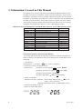


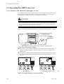
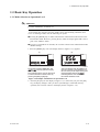

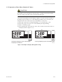
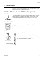
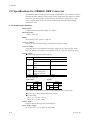
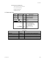
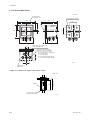
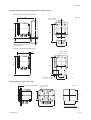

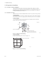
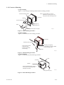
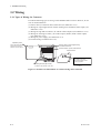
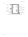
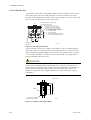
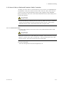

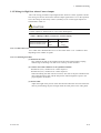

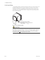

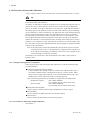
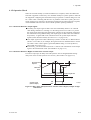
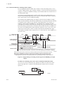


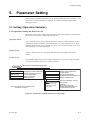
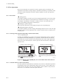
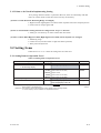

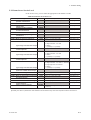
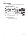

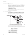
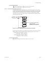
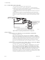

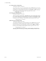
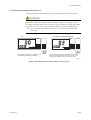
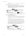
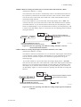

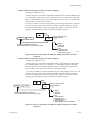


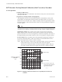
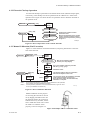
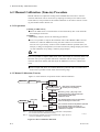
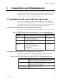
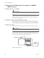
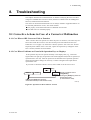
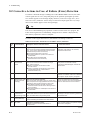
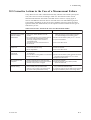
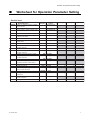
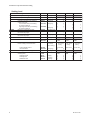
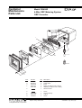
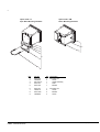

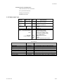


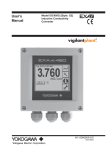


![SS400G MLSS Converter [Style:S2.2]](http://vs1.manualzilla.com/store/data/005726371_1-b873ef07ceb169a0226d293b313a67fd-150x150.png)

![Model ISC450G [Style: S2] Inductive Conductivity](http://vs1.manualzilla.com/store/data/005904832_1-e9e6bdf8409b6fd37a184b6e2701b530-150x150.png)