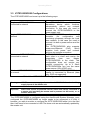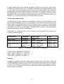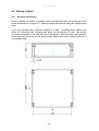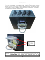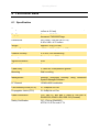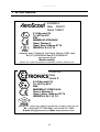
1
Operating Manual
iCITE100/EX2000/EX2000X
II 2 G Ex emb II T4
Operating Manual
This page is intentionally left blank.
Document Number 318847 (See Last Page for Revision Details)
©2012 Extronics Limited. This document is Copyright Extronics limited.
Extronics reserve the right to change this manual and its contents without notice, the latest
version applies.
2
Operating Manual
Contents
1
2
Introduction.......................................................................................................... 4
Safety Information and Notes .............................................................................. 5
2.1 Storage of this Manual................................................................................... 5
2.2 ATEX Special Conditions for Safe Use.......................................................... 5
2.3 List of Notes .................................................................................................. 5
3 Structure and Function ........................................................................................ 7
3.1 Applications ................................................................................................... 7
3.2 Features and Benefits ................................................................................... 7
3.3 iCITE100/EX2000 Configurations .................................................................. 9
4 Installation and Setting-to-Work ........................................................................ 11
4.1 Installation ................................................................................................... 11
4.1.1 Removing the cover .............................................................................. 11
4.1.2 Installing Cables For Master iCITE100/EX2000 .................................... 13
4.1.3 Installing Cables For Slave iCITE100/EX2000 ...................................... 16
4.2 Setting to Work ............................................................................................ 19
4.2.1 Mounting Information ............................................................................ 19
4.3 Intended Purpose Usage ............................................................................. 21
4.4 Transportation and Storage ......................................................................... 21
4.5 Authorized Persons ..................................................................................... 21
4.6 Cleaning and Maintenance .......................................................................... 21
4.7 Safety Precautions ...................................................................................... 22
4.8 Cleaning and Maintenance Intervals ........................................................... 22
4.9 Aggressive substances and environments .................................................. 22
4.10
Exposure to external stresses .................................................................. 22
5 Warranty Information ......................................................................................... 23
6 Technical Data .................................................................................................. 24
6.1 Specification ................................................................................................ 24
7 ATEX Labels ..................................................................................................... 25
8 ATEX Certificate ................................................................................................ 26
9 EC Declaration of Conformity ............................................................................ 29
10
Manual Revision ............................................................................................. 31
3
Operating Manual
1 Introduction
The Extronics iCITE100/EX2000 is a Zone 1 approved version of the Aeroscout
EX2000 which is a hardware component of AeroScout's industry-leading visibility
system for active RFID and location applications. The iCITE100/EX2000 adds value
by extending the system to provide robust and sophisticated RFID detection and
identification capabilities, using the same Wi-Fi-based Active RFID tags that can also
be accurately located in real time by the AeroScout system.
The iCITE100/EX2000 uses a 125KHz ASK modulated field to trigger Extronics
iTAG100 devices as they come within range of the iCITE100/EX2000 field. This
causes the tags to transmit a 2.4GHz WIFI message that is received by a Location
Receiver or compatible access point. This provides instant knowledge that a tagged
asset or person passed through a gate, doorway or some other tightly defined area.
There are two variants of the iCITE100/EX2000; master and slave. The master unit
may be operated in stand-alone mode, supplied either by IEEE802.3af compliant
power-over-Ethernet (POE) or from a 24VAC/DC supply. The master unit
communicates with the Aeroscout software via 10/100BASET Ethernet.
The slave unit must be connected to a master unit, as it is powered from the master
and also receives synchronisation data via RS485. Up to three slave units may
‘chained’ in series from one master unit. The slave units are used to extend the range
of a master unit, for example to reach both sides of a large doorway.
The iCITE100/EX2000 is marked as EEx II 2 G Ex emb II T4 -20oC ≤ Tamb ≤ 60oC
4
Operating Manual
2 Safety Information and Notes
2.1 Storage of this Manual
Keep this user manual safe and in the vicinity of the device. All persons who have to work on
or with the device should be advised on where the manual is stored.
2.2 ATEX Special Conditions for Safe Use
A slave unit may be connector to a master unit, another slave unit and/or a power
supply of up to 24V a.c./d.c. A master unit may be connected to a slave unit and/or a
power supply of up to 48V a.c./d.c.
2.3 List of Notes
The notes supplied in this chapter provide information on the following.
• Danger / Warning.
o Possible hazard to life or health.
• Caution
o Possible damage to property.
• Important
o Possible damage to enclosure, device or associated equipment.
• Information
o
Notes on the optimum use of the device
Warning
Please read EC type certificate Baseefa07ATEX0181X and this manual
before installing the iCITE100/EX2000
Warning
Installation and maintenance of the iCITE100/EX2000 must only be
carried out by suitably qualified personnel. The equipment must be
installed in accordance with EN60079-0, EN60079-14 and the Accident
Prevention Regulations.
Warning
Never connect a supply of more than 24VDC/24VAC to the Auxiliary
supply inputs of the master unit.
Warning
Never connect a slave unit to a master unit which is powered via PoE or
a 48V supply.
Warning
Never connect a slave unit to anything except a master unit or another
slave unit.
Warning
Always follow the connection diagrams in the manual.
5
Operating Manual
Warning
All cables connected to the iCITE100/EX2000 to be installed using the
correct Ex e cable glands, to be fitted by a competent person.
Warning
The user MUST ensure that any cables connected to the
iCITE100/EX2000 have adequate mechanical protection to avoid damage
to the wires. Failure to do so could cause shorts or exposure of noninsulated wires to potentially explosive environments.
Warning
Any cable glands which are not in use MUST be replaced by a suitable
EX e certified stopping plug.
Important
Ensure the lid is secure, correct cable glands are fitted and the unit is
correctly wired and earthed before applying power to the
iCITE100/EX2000.
Important
Slave units cannot be powered via PoE. Slave units can be connected to
a master unit (providing the master unit is powered via 24V ac/dc), or to
another slave unit.
Important
The master and slave iCITE100/EX2000s have different terminal
connections. Follow the correct pin connections for the unit being
installed.
6
Operating Manual
3 Structure and Function
3.1 Applications
Theft Prevention and Security
Facilities and general enterprises can tag valuable assets that are intended to stay
within a certain area. The system can track the location of those assets, and if they
leave through an exit or enter a restricted area, the iCITE100/EX2000 will trigger an
alert.
Process Control
Manufacturing and supply chain facilities can track the location and presence of
equipment and in process inventory as it moves through the production process. This
gives an enterprise a real-time view of which (and how many) assets have passed
each step in the process, enabling better supply chain management.
Reduced Searching Time
The iCITE100/EX2000 can identify an individual asset among many similar assets,
such as WIP items on a shelf in manufacturing, or hospital infusion pumps in a
storage room. The person initiating the search will not only know the location of the
asset, but can also make the tag physically identify itself by triggering the LED on the
desired tag.
Inventory Management
Logistics and manufacturing enterprises can automatically up-date inventory records
based on assets currently within defined areas, ensuring real-time knowledge of
levels without manual checks or physical scanning.
Business Event Automation
Any type of enterprise can use the iCITE100/EX2000 to trigger automated events
and alerts that occur based on the location of an asset. For example, when a set
number of pieces of inventory pass by an iCITE100/EX2000 to enter a processing
area, the floor supervisor can receive a pager alert to redistribute staff to that area.
3.2 Features and Benefits
Long Range RFID Detection of Extronics iTAG100 Tags
The iCITE100/EX2000 triggers the iTAG100 causing them to transmit as they pass
through a defined area. ICITE100/EX2000 have up to a 6m (20 ft) range, enough to
cover wide gate areas, and can also be adjusted to cover areas as small as 50cm (20
inches)
Highly Accurate location Detection
The iCITE100/EX2000 enables enterprises to locate assets precisely to a specific
shelf, rack, workstation (in manufacturing) or bed (in healthcare). In addition the
iCITE100/EX2000 can assist in difficult searches by distinguishing between similar
nearby assets, and making the right tag identify itself by blinking.
7
Operating Manual
Tag Behaviour Modification
The iCITE100/EX2000 can activate and deactivate iTAG100s, extending a tags
battery life further by switching them off when they leave a defined tracking area. It
can change of tag transmission rate and other tag programming for a temporary or
indefinite time to accommodate different usage patterns.
Telemetry and Data Functions
These functions provide the ability to use an iCITE100/EX2000 to store messages on
the tag for later transmission. Message transmission can later be triggered by
another iCITE100/EX2000, enabling sophisticated process control functions. The
iCITE100/EX2000 can trigger a tag to store and transmit up to ten bytes of data.
Rugged IP66-Eated Enclosure
This allows the iCITE100/EX2000 to be used in any hostile indoor or outdoor
environment and in a wide temperature range.
iCITE100/EX2000 Chaining
Chaining enables multiple iCITE100/EX2000 units to be connected together for full,
precise coverage of areas such as large doorways. Up to three slave units may be
daisy-chained from one master unit using 4-pair CAT5 cable.
8
Operating Manual
3.3 iCITE100/EX2000 Configurations
The iCITE100/EX2000 can be set up in the following ways:
Connection Method
Single
iCITE100/EX2000
connected to network
Description
not The iCITE100/EX2000 can be used as
standalone device which functions
independently without any network
connection. In this case you need to
connect the iCITE100/EX2000 to the
power supply only.
Single iCITE100/EX2000 – connected to The iCITE100/EX2000 can be remotely
network
controller
(for
configuration
and
monitoring purposes) through the local
area network. In this case you need to
connect it to both a power source and the
network.
The iCITE100/EX2000 also supports
power-over-Ethernet
(PoE),
which
supplies both power and network
services via a single connection.
Chained iCITE100/EX2000s – not iCITE100/EX2000s may be connected to
connected to network
each other in a chain and receive the
power/data
from
one
Master
iCITE100/EX2000 in the chain. This
configuration does not require any
network connectivity. Up to 3 Slave
iCITE100/EX2000s can use the same
power source (24V AC/DC only)
Chained iCITE100/EX2000s – connected As per chained iCITE100/EX2000s but
to network.
master is connected to Ethernet (data
only, POE not supported).
Table 3.1 – iCITE100/EX2000 Configuration Methods
–
Warning
NEVER connect a supply of more than 24VDC/24VAC to the Auxiliary
supply inputs of the master unit.
Important
Slave units cannot be powered via PoE. Slave units can be connected to
a master unit (providing the master unit is powered via 24V ac/dc), or to
another slave unit.
The iCITE100/EX2000 is configured using the AeroScout® System Manager, once
configured the iCITE100/EX2000 no longer needs to be connected to a LAN. If
however, you wish to monitor or configure the iCITE100/EX2000 while it is in the field
then it will need to be connected a LAN. The slave units are automatically updated by
the master unit.
9
Operating Manual
Information Consult with the AeroScout® System Manager documentation for
information on configuring the iCITE100/EX2000’s software features.
This manual only concerns the mechanical and wiring setup of the
iCITE100/EX2000’s.
When operating as a single iCITE100/EX2000 the following configuration methods
are possible; if updating and monitoring of the units is required, the master can be
connected to a LAN, and powered via either a PoE connection or an external 24V
ac/dc power supply as shown in Figure 3.1.
Figure 3.1 – Master iCITE100/EX2000 Configurations
A master unit can support up to three slave units from a single 24V ac/dc power
supply. The slaves are powered using a RS485 connection. In this configuration the
last slave in the chain needs to be terminated, as described in section 4.1.3.
Figure 3.2 – Master-Slave-Slave iCITE100/EX2000 Configuration
10
Operating Manual
4 Installation and Setting-to-Work
4.1 Installation
The iCITE100/EX2000 is simple to install and can be secured directly to a suitable
surface using the mounting holes on the enclosure
Important
4.1.1
All cables connected to the iCITE100/EX2000 to be installed using the
correct Ex e cable glands, to be fitted by a competent person.
Removing the cover
Using a 5mm Allen key unscrew all four screws located in the corners of the box as
indicated below in Figure 4.1. (Note that these are captive screws that are retained in
the lid).
Figure 4.1 – iCITE100/EX2000 Enclosure access screw locations
After removing the cover the iCITE100/EX2000 antenna and screw terminals will be
exposed. You will need to remove the antenna to gain access to the Ex e screw
11
Operating Manual
terminals. To do this remove the 4 bolts as indicated in Figure 4.2 and carefully lift
the antenna off the screw pillars. The antenna will come pre installed, when removing
the antenna, be careful not to put a strain on the wires connected to the antenna. It is
not necessary to remove the wires connecting the antenna to the PCB from the
screw terminals to complete installation.
Figure 4.2 – View of iCITE100/EX2000 with Enclosure Lid Removed
12
Operating Manual
Table 4.1 below describes which wire each cable gland should be used for. If one of
the cables is not required due to the configuration required the cable gland(s) not in
use must be replaced with a suitably certified stopping plug.
Gland
1
2
3
Master Purpose
Slave Purpose
Ethernet
Not used stopping plug fitted
External Power In
RS485 Out
RS485 Out
RS485 In
Table 4.1 – Cable to Gland Descriptions
Important
The master and slave iCITE100/EX2000s have different terminal
connections. Follow the correct pin connections for the unit being
installed.
To identify the master and slave versions, look at the screw terminals. There is a row
of 21 terminals on the master version, whilst the slave has a row of 25.
4.1.2
Installing Cables For Master iCITE100/EX2000
Warning
The user MUST ensure that any cables connected to the
iCITE100/EX2000 have adequate mechanical protection to avoid damage
to the wires. Failure to do so could cause shorts or exposure of noninsulated wires to potentially explosive environments.
C2
C3
C1-1
C1-21
Figure 4.3 – View of iCITE100/EX2000 Master Unit Screw Terminals
13
Operating Manual
Depending on the configuration required there may be stopping plugs instead of
cable glands in the enclosure. For example if the unit is to be used as a single
iCITE100/EX2000 with no Ethernet connection, only a power supply will be needed.
Therefore only the middle cable gland will be needed and the other 2 glands will be
replaced with stopping plugs.
Warning
Any cable glands which are not in use MUST be replaced by a suitable
EX e certified stopping plug.
Ethernet and RS485 connections should be made using Cat-5 cables, the diagram
below shows the pin/wire connections of a typical Cat-5 cable once stripped.
Cat-5 Wire
1
Colour
White/Orange
2
Orange
3
White/green
4
Blue
5
White/blue
6
Green
7
White/brown
8
Brown
Table 4.2 - Cat-5 Cable Wiring Descriptions
Ethernet Connection
To connect a Cat-5 cable to the Ethernet screw terminals, feed the cable through the
left-most cable gland and strip the wire to expose the 8 individual wire cores as
describes above in table 4.2 and also the outer sheath. Terminate the wires and
outer sheath in bootlace ferrules. The earth wire should be sleeved. Place the correct
wires into the corresponding screw terminal, i.e. cat-5 wire 1 into Ethernet – 1 and
cat-5 wire 8 into Ethernet – 8. Place the terminated outer sheath into the earth
terminal C1-21. Ensure the wires are securely screwed into place.
Power Connection
If the iCITE100/EX2000 is to be powered via an external power source, ensure the
power supply is 24V ac/dc only. Feed the cable through the middle cable gland and
strip the wire to expose the two power lines and the outer sheath, then strip and
terminate the exposed wires with bootlace ferrules. The earth wire should be sleeved.
Place the wires into the corresponding screw terminal as indicated in below in table
4.3. The earth wire should be placed into screw terminal C1 – 10. Ensure the wires
are securely screwed in place.
14
Operating Manual
RS485 Connection
If the iCITE100/EX2000s are to be used in chained mode the RS485 Out pins on the
master unit (connector 1) will be used to connect the first slave unit. The RS485
connection should also be made using a Cat-5 cable. Feed the cable through the
right hand cable gland, then strip and terminate the wires with bootlace ferrules. The
earth wire should be sleeved. Place the outer sheath into the earth terminal C1-1 and
the corresponding cat-5 wires into the RS485 screw terminal as described below in
table 4.3, i.e. Cat-5 wire 1 into RS485 – 1. Ensure the wires are securely screwed in
place.
Earthing
Connector 3 contains two earth screw terminals which are to be used to earth the
iCITE100/EX2000. Connect one of the earth terminals to the earthing lug connected
to the iCITE100/EX2000’s enclosure. The second screw terminal for earth is a spare;
you can use this should you have any extra wires which need earthing from the
power supply for example.
Master Connector/Pin No. Pin Description
C1 - 1
Earth (Ethernet outer sheath)
C1 - 2
Ethernet – 1
C1 - 3
Ethernet – 2
C1 - 4
Ethernet – 3
C1 - 5
Ethernet – 4
C1 - 6
Ethernet – 5
C1 - 7
Ethernet – 6
C1 - 8
Ethernet – 7
C1 - 9
Ethernet – 8
C1 - 10
External Power +
C1 - 11
External Power C1 - 12
Earth (Power cable outer sheath)
C1 - 13
RS485 Out – 1
C1 - 14
RS485 Out – 2
C1 - 15
RS485 Out – 3
C1 - 16
RS485 Out – 4
C1 - 17
RS485 Out – 5
C1 - 18
RS485 Out – 6
C1 - 19
RS485 Out – 7
C1 - 20
RS485 Out – 8
C1 - 21
Earth (Chain Out)
C2 - 1
Long Range Antenna + (Blue)
C2 - 2
Long Range Antenna – (Green)
C2 - 3
Short Range Antenna + (Red)
C2 - 4
Short Range Antenna – (Black)
C3 - 1
Earth
C3 - 2
Earth
Table 4.3 – Master iCITE100/EX2000 Screw Terminals Description
15
Operating Manual
Figure 4.4 – View of iCITE100/EX2000 Slave Unit Screw Terminals
4.1.3
Installing Cables For Slave iCITE100/EX2000
The slave iCITE100/EX2000’s are powered and controlled via a master unit. RS485
is fed into a slave unit from a master unit. It is possible to have 2 slave units attached
to a master unit in a chain. The first slave will accept an RS485 input from the
master, this unit will then send an RS485 output to the input of the second slave unit.
The last slave in the chain will then need to be terminated for the chain to work
correctly.
RS485 In Connection
RS485 in pins on connector 1 will be used to connect the unit to either a master or
another slave unit’s RS485 out terminals. The RS485 connection should be made
using a cat-5 cable. Feed the cable through the left hand cable gland, then strip and
terminate the wires with bootlace ferrules. The earth wire should be sleeved. Place
the outer sheath into the earth terminal C1-1 and the corresponding cat-5 wires into
the RS485 screw terminal as described below in table 4.5, i.e. cat-5 wire 1 into
RS485 In – 1. Ensure the wires are securely screwed in place.
RS485 Out Connection
16
Operating Manual
If another slave is to be connected to the RS485 Out pins on connector 1 will be used
to connect the second slave unit. The RS485 connection should also be made using
a cat-5 cable. Feed the cable through the right hand cable gland, then strip and
terminate the wires with bootlace ferrules. The earth wire should be sleeved. Place
the outer sheath into the earth terminal C1-18 and the corresponding cat-5 wires into
the RS485 Out screw terminal as described below in table 4.5, i.e. cat-5 wire 1 into
RS485 out – 1. Ensure the wires are securely screwed in place.
Termination Jumper Setup
The last slave in a chain needs to be terminated. Therefore if only one slave is used
this slave automatically needs to be terminated. If two slaves are used the second
slave needs to be terminated and the first slave needs to remain un-terminated.
Termination is applied to a slave unit by setting jumpers between the termination
terminals on connector 1 accordingly. The table below describes if the termination
methods required for various configurations.
Using table 4.4, setup the slave units as required, using suitable wire crimped and
securely screwed in place.
Configuration
Termination
Term1-Term2
Term3
Required?
Configuration
configuration
Master-Slave1
Yes slave1
Linked
A+B
Master-Slave1-Slave2 No-Slave1
Slave1 – Not Linked
Slave1 - B+C
Yes-Slave2
Slave2 – Linked
Slave2 – A+B
Master-Slave1-Slave2- No-Slave1,
Slave1 – Not Linked
Slave1 - B+C
Slave 3
Slave 2 Yes- Slave2 – Not Linked
Slave 2 – B+C
Slave3
Slave 3 – Linked
Slave 3 – A+B
Table 4.4 – Termination Jumper Setting Configuration.
Term 1 linked = wire link C1-1 and C1-2
Term 2 linked = wire link C1-3 and C1-4
Term 3 A+B = wire link C1-5 and C1-6
Term 3 B+C = wire link C1-6 and C1-7
Earthing
Connector 3 contains two earth screw terminals which are to be used to earth the
iCITE100/EX2000. Connect one of the earth terminals to the earthing lug connected
to the iCITE100/EX2000’s enclosure. The second screw terminal for earth is a spare;
you can use this should you have any extra wires which need earthing from the
power supply for example.
17
Operating Manual
The following table provides slave screw terminal descriptions.
Slave Connector/Pin No.
C1 - 1
C1 - 2
C1 - 3
C1 - 4
C1 - 5
C1 - 6
C1 - 7
C1 - 8
C1 - 9
C1 - 10
C1 - 11
C1 - 12
C1 - 13
C1 - 14
C1 - 15
C1 - 16
C1 - 17
C1 - 18
C1 - 19
C1 - 20
C1 - 21
C1 - 22
C1 - 23
C1 - 24
C1 - 25
C2 - 1
C2 - 2
C2 - 3
C2 - 4
C3 - 1
C3 - 2
Pin Name
Term1A
Term1B
Term2A
Term2B
Term3A
Term3B
Term3C
Earth
Chain Output – 8
Chain Output – 7
Chain Output – 6
Chain Output – 5
Chain Output – 4
Chain Output – 3
Chain Output – 2
Chain Output – 1
RS485 Input – 8
RS485 Input – 7
RS485 Input – 6
RS485 Input – 5
RS485 Input – 4
RS485 Input – 3
RS485 Input – 2
RS485 Input – 1
Earth
Short Range Antenna + (Red)
Short Range Antenna – (Black)
Long Range Antenna + (Blue)
Long Range Antenna – (Green)
Earth
Earth
Table 4.5 – Slave iCITE100/EX2000 Screw Terminal Descriptions
18
Operating Manual
4.2 Setting to Work
4.2.1
Mounting Information
Once all cables have been connected, place the antenna back over the pillars in the
same orientation as in figure 4.2. Securely fasten the antenna using the washers and
bolts.
If you are mounting the enclosure directly to a wall / mounting plate, please see
below for mounting hole locations and sizes (all dimensions in mm). You should
mount the enclosure to the wall with the lid removed to allow access to the mounting
holes, then refit the enclosure lid and securely tighten the screws making sure not to
over tighten them.
19
Operating Manual
If you are mounting the enclosure to a pipe using the Extronics pipe mounting
bracket (Extronics Part number A070031), please see below for mounting details.
Your enclosure should be supplied with the pipe mount bracket fitted. The bracket is
designed for mounting to a 2” diameter pipe:
Tighten nuts
here to secure
to pole.
Important
Ensure the lid is secure, correct cable glands are fitted and the unit is
correctly wired and earthed before applying power to the
iCITE100/EX2000
20
Operating Manual
4.3 Intended Purpose Usage
Important
Before setting the units to work, read the technical documentation
carefully.
Important
The latest version of the technical documentation or the corresponding
technical supplements is valid in each case.
The iCITE100/EX2000 is built using modern components and is extremely reliable in
operation; however it must only be used for its intended purpose. Please note that
the intended purpose also includes compliance with the instructions issued by the
manufacturer for installation, setting up and service.
Any other use is regarded as conflicting with the intended purpose. The manufacturer
is not liable for any subsequent damage resulting from such inadmissible use. The
user bears the sole risk in such cases.
4.4 Transportation and Storage
All iCITE100/EX2000 devices must be so transported and stored that they are not
subjected to any excessive mechanical stresses.
4.5 Authorized Persons
Only persons trained for the purpose are authorized to handle the iCITE100/EX2000;
they must be familiar with the unit and must be aware of the regulation and provisions
required for explosion protection as well as the relevant accident prevention
regulations.
4.6 Cleaning and Maintenance
The iCITE100/EX2000 and all its components require no maintenance. All work on
the iCITE100/EX2000 by personnel who are not expressly qualified for such activities
will cause the Ex approval and the guarantee to become void.
21
Operating Manual
4.7 Safety Precautions
Important
For the installation, maintenance and cleaning of the units, it is
absolutely necessary to observe the applicable regulations and
provisions concerned with explosion protection (EN 60079-0, EN 6007914) as well as the Accident Prevention Regulations.
4.8 Cleaning and Maintenance Intervals
The cleaning intervals depend on the environment where the system is installed.
4.9 Aggressive substances and environments
The iCITE100/EX2000 is not designed to come into contact with aggressive
substances or environments, please be aware that additional protection may be
required.
4.10 Exposure to external stresses
The iCITE100/EX2000 is not designed to be subjected to excessive stresses e.g.
vibration, heat, impact. Additional protection is required to protect against these
external stresses.
The iCITE100/EX2000 will require additional protection if it is installed in a location
where it may be subjected to damage.
22
Operating Manual
5 Warranty Information
The Customer shall carry out a thorough inspection of the delivered project or
equipment with 21 days of delivery and shall give immediate written notification to the
Company of any omissions, defects or faults.
The Company warrants that the project or equipment delivered shall accord with the
Quotation or Pricing Schedule and related Company specifications, but it does not
warrant its fitness for any other purpose.
Extronics will make good, by repair or at Extronics option by the supply of a
replacement, defects which, under proper use in accordance with specifications and
manufacturer’s instructions, appear in the goods within a period of twelve calendar
months after the goods have been delivered and arise solely from faulty design,
materials or workmanship, provided always that defective parts have been returned
to Extronics if Extronics shall have so required.
The warranty of any goods is based upon a return to Extronics factory (Return to
Base Warranty) which will be at the Customers cost. The repaired or new parts will
be delivered by Extronics carriage paid. If you allege that goods are totally unfit for
their purpose they must be returned within 7 days of receipt. Site Warranty is
expressly excluded from these terms and conditions unless agreement is made in
writing between the parties it.
Extronics liability under this clause shall be in lieu of any warranty or condition
implied by law as to the quality or fitness for any particular purpose of the goods, and
save as provided in this clause Extronics shall not be under any liability, whether in
contract, or otherwise, in respect of defects in goods delivered or for any injury other
(than personal injury caused by Extronics negligence as defined in Section 1 of the
Unfair Contract Terms Act, 1977), damage or loss resulting from such defects or from
any work done in connection therewith, provided however that nothing in this clause
shall operate to exclude any warranty or condition implied by law as to the quality of
the goods in the event that the goods when sold by you or when sold by any person
or persons to whom you may sell the goods shall become the subject of a consumer
sale as defined in the Supply of Goods (Implied Terms) Act, 1973 except that any
claim under such warranty or condition shall have arisen from any act or omission by
you or by any person or persons selling the goods by way of a consumer sale.
23
Operating Manual
6 Technical Data
6.1 Specification
Range
Adjustable from 50 centimetres to 6.5 metres (20
inches to 21 feet)
Tag Type
Extronics iTAG100 tags
Aeroscout TAG2000X tags
Dimensions
250 x 250 x 120 mm (w x h x d)
9.85 x 9.85 x 4.72 inches
Weight
Approx 2.5 Kg (5.5 lbs)
Ambient Temperature
-20ºC to +60ºC (-4ºF to +140ºF)
Relative humidity
0 to 95%, non-condensing
Housing
Black antistatic GRP enclosure
Ingress Protection
IP66
Electrical Connection
Screw terminals
Cable Entry
3 x M20 Ex e compression glands
Mounting
Wall or ceiling
Management
Settings configured remotely using Aeroscout
System Manager Software
LF Channel
125KHz ASK modulation
Field Intensity Limits (ETSI)
37.3 dBµA/m at 10m
Propagation Limits (FCC)
21.8 dBµV/m at 10m
Radio Certification
FCC Part 15, sub part C class B, sub part B,
EN300-330, EN301-489, RSS 210 (Canada)
Safety Certification
CE, cTUVus (EN60950)
ATEX II 2 G Ex emb II T4
24
Operating Manual
7 ATEX Labels
EX-2000-X
Date 12/05/11
Serial 104561
xxxx
II 2 G Ex emb II T4
Ta –20°C to 60°C
IP66
BASEEFA 07 ATEX 0181X
Class I, Division 2
Class I, Zone 1 AEx em IIC T4
GROUPS A, B, C, D, T4
Aeroscout Israel, 3 Pekeris St, Park Tamar, Rehovot, 76702, Israel
Tel: [371] 97289369393 Fax: [972] 97289365977
www.aeroscout.com
Manufactured By:
Extronics Ltd, 1 Dalton Way, Midpoint 18, Middlewich, Cheshire, CW10 0HU, UK
iCITE100
Date
Serial #
xxxx
II 2 G Ex emb II T4
Ta –20°C to 60°C
IP66
BASEEFA 07 ATEX 0181X
Class I, Division 2
Class I, Zone 1 AEx em IIC T4
GROUPS A, B, C, D, T4
Extronics Ltd 1 Dalton Way, Midpoint 18, Middl ewich, Cheshire CW10 0HU UK
Tel: +44(0) 845 277 5000 Fax: +44 (0) 845 277 4000
E-mail: [email protected] Web: www.extronics.com
25
Operating Manual
8 ATEX Certificate
26
Operating Manual
27
Operating Manual
28
Operating Manual
9 EC Declaration of Conformity
29
Operating Manual
30
Operating Manual
10 Manual Revision
Revision
01
02
03
04
05
06
07
Description
Current revision
Image Updated
Added special cond. safe use and warranty
info. Updated EC DoC, added ATEX
certificate and ATEX label
Updated mounting information
Updated DoC
Updated wiring information
Swapped slave SR/LR terminals
31
Date
07/12/2007
27/03/2009
16/07/2012
By
AJR
JRE
BTS/AJR
17/06/2013
05/07/2013
10/06/2014
11/09/2014
AJP
AJR
AJR
BTS