1
H Y DI- Language Tutorial
A. Cimatti
S. Mover
October 14, 2013
S. Tonetta
Contents
1
2
H Y DI: an overview
1.1 Modules . . . . .
1.2 Processes . . . .
1.3 Synchronizations
1.4 Running example:
. . . . . . . . . .
. . . . . . . . . .
. . . . . . . . . .
Three-tank model
.
.
.
.
.
.
.
.
.
.
.
.
.
.
.
.
.
.
.
.
.
.
.
.
.
.
.
.
.
.
.
.
.
.
.
.
.
.
.
.
.
.
.
.
.
.
.
.
.
.
.
.
.
.
.
.
.
.
.
.
.
.
.
.
.
.
.
.
.
.
.
.
2
2
4
4
5
H Y DI module definition
2.1 Variable declaration . . . . .
2.1.1 Discrete variables . .
2.1.2 Continuous variables
2.2 Event declaration . . . . . .
2.3 Initial condition . . . . . . .
2.4 Invariant condition . . . . .
2.5 Transitions . . . . . . . . .
2.5.1 Discrete transitions .
2.5.2 Continuous transition
2.6 Urgent conditions . . . . . .
2.7 Submodules . . . . . . . . .
2.8 Reserved keywords . . . . .
2.9 Three-tanks model . . . . .
.
.
.
.
.
.
.
.
.
.
.
.
.
.
.
.
.
.
.
.
.
.
.
.
.
.
.
.
.
.
.
.
.
.
.
.
.
.
.
.
.
.
.
.
.
.
.
.
.
.
.
.
.
.
.
.
.
.
.
.
.
.
.
.
.
.
.
.
.
.
.
.
.
.
.
.
.
.
.
.
.
.
.
.
.
.
.
.
.
.
.
.
.
.
.
.
.
.
.
.
.
.
.
.
.
.
.
.
.
.
.
.
.
.
.
.
.
.
.
.
.
.
.
.
.
.
.
.
.
.
.
.
.
.
.
.
.
.
.
.
.
.
.
.
.
.
.
.
.
.
.
.
.
.
.
.
.
.
.
.
.
.
.
.
.
.
.
.
.
.
.
.
.
.
.
.
.
.
.
.
.
.
.
.
.
.
.
.
.
.
.
.
.
.
.
.
.
.
.
.
.
.
.
.
.
.
.
.
.
.
.
.
.
.
.
.
.
.
.
.
.
.
.
.
.
.
.
.
.
.
.
.
.
.
.
.
.
.
.
.
.
.
.
.
.
.
.
.
.
.
.
.
.
.
.
.
.
.
.
.
.
.
.
.
.
.
.
.
.
.
.
.
.
.
.
.
.
.
.
.
.
.
.
.
.
.
8
8
9
9
9
10
10
11
11
13
14
14
15
15
Network of processes
3.1 Overview . . . . . . . . .
3.2 Process Instantiation . . .
3.3 Synchronization constraints
3.3.1 Message passing .
.
.
.
.
.
.
.
.
.
.
.
.
.
.
.
.
.
.
.
.
.
.
.
.
.
.
.
.
.
.
.
.
.
.
.
.
.
.
.
.
.
.
.
.
.
.
.
.
.
.
.
.
.
.
.
.
.
.
.
.
.
.
.
.
.
.
.
.
.
.
.
.
.
.
.
.
.
.
.
.
.
.
.
.
.
.
.
.
18
18
18
19
21
4
Language extensions
4.1 Shared variables . . . . . . . . . . . . . . . . . . . . . . . . . . . . .
4.2 Explicit scheduler . . . . . . . . . . . . . . . . . . . . . . . . . . . .
23
23
24
5
Current limitations
26
3
.
.
.
.
1
Chapter 1
H Y DI: an overview
A H Y DI model is given by a set of modules, a set of processes, and a set of synchronization constraints. Figure 1.1 shows a small example of the H Y DI specification of
two gates. A gate is open, closed, it is opening or closing. Both gates must open and
close together.
1.1
Modules
H Y DI modules (e.g., the Gate module) extend SMV modules in order to specify
explicitly the events used for synchronization and timing aspects such as continuous
variables and flow conditions. The SMV language has been widely used to specify
complex finite-state systems. The system description is typically decomposed into
modules. Essentially, a module is a set of declarations and constraints on the declared
variables. Modules can be instantiated several times and nested to form a complex
synchronous hierarchy.
In particular, modules may contain VAR sections with the declaration of state variables (the states of the system consist of assignments to these variables); IVAR sections with the declaration of input variables (the transitions of the system consist of
two states and an assignment to these input variables); INIT constraints which must
be satisfied by the valid initial states; INVAR constraints which must be satisfied by
any valid state; and TRANS constraints which must be satisfied by any valid transition.
For example, the state s1 = hlocation = opened, timer = 10i is a valid state but not
initial; it can go to the state s2 = hstate = closing, timer = 0i but not to the state
s3 = hstate = closing, timer = 10i (because the transition would violate the constraint next(timer) = 0). We refer the reader to [CCCJ+ 02] for the last version of the
syntax used by the model checker N U SMV [CCG+ 02] and to [McM93] for a formal
definition of its semantics.
H Y DI modules inherit all the constructs of SMV modules and add three main new
features:
• events, a list of symbols used in the synchronizations; these are introduced with
the keyword EVENT, which can also be used in the TRANS constraints as it was
an input variable; intuitively, transitions are distinguished by the event which is
being fired; for example, the transition from state s1 to state s2 is labelled with
the event closing.
2
MODULE main
VAR gate1 : gate;
VAR gate2 : gate;
SYNC gate1, gate2 EVENTS open, open;
SYNC gate1, gate2 EVENTS close, close;
MODULE gate
VAR
location : {closed, opening, opened, closing};
timer : continuous;
EVENT open, close, tau;
INIT
location = closed & timer = 0;
TRANS
EVENT = open ->
(location = closed & next(location) = opening & next(timer) = 0)
TRANS
EVENT = close ->
(location = opened & next(location) = closing & next(timer) = 0)
TRANS
EVENT = tau ->
(
(location = opening & next(location) = opened) |
(location = closing & next(location) = closed)
)
TRANS
EVENT = tau -> (timer >= 10 & next(timer) = timer)
INVAR
(location = opening -> timer <= 10) &
(location = closing -> timer <= 10)
FLOW
(location in {closed, opened) -> der(timer) = 0) &
(location = {opening, closing} -> der(timer) = 1)
Figure 1.1: A small H Y DI example.
3
• continuous variables, a new type of variables declared with the keyword
continuous; these are variables which are allowed to change in a timed transition and evolve according to some function continuous in time; for example,
the variable timer is continuous and changes only during timed transitions; all
other variables (boolean, real, integer, etc.) are considered discrete, i.e., they
change only during discrete instantaneous transitions.
• flow conditions, used to constrain the continuous evolution of continuous variables; the constraints are introduced with the keyword FLOW and may refer to
the derivatives of continuous variables, denoted with der; for example, in the
state s2 , the variable timer can only increase.
Intuitively, the system performs discrete and continuous transitions. In the former case, the whole system evolves as stated in the TRANS declarations. In the latter case, the discrete variables do not change, while the continuous variables change
according to the FLOW conditions and to the elapsed time. For example, s2 =
hstate = closing, timer = 0i moves to s3 = hstate = closing, timer = 10i with
a continuous transition if der(timer) = 10 and the elapsed time is 10.
1.2
Processes
H Y DI processes are instantiation of H Y DI modules (in the example, gate1 and
gate2 are processes). Differently from SMV processes, they can run both asynchronously or synchronize on shared events. Processes are declared in the main module of a H Y DI model. They represent the components of a network whose topology
is defined by the synchronizations. The network is not hierarchical in that there is no
further asynchronous decomposition of a process, although the modules may contain
synchronous instantiation of other modules.
Processes can share variables through the passage of parameters in the instantiations. However, they are limited to read the variables of other processes. This permits
an easy identification of when the variables do not change even if the transitions are described with a generic relation (compared to a more restrictive functional description).
1.3
Synchronizations
Synchronizations specify if two events of two processes must happen at the same time.
If two events are not synchronized, they interleave. Such synchronization is quite standard in automata theory and process algebra. It has been generalized with guards to
restrict when the synchronization can happen. In the example, all the transitions of
gate1 labelled with open have to synchronize with a transition of gate2 labelled with
open.
In order to capture the semantics of some design languages, it is necessary to enrich
the synchronization with further constraints that specify a particular policy scheduling
the interaction of the processes. For this reason, it is possible to specify a scheduler in
the main module of the H Y DI model in terms of state variables, initial and transition
conditions. These conditions may predicate over the events of the processes.
4
start
start
empty
l˙ = 0
ṫ = 1
l=0
emptying
l˙ = −10
ṫ = −1
l ∈ [0, C]
0≤t
τ ∧ l = 0 ∧ t := 0
τ ∧t≥M
τ
unf illed ∧ t ≥ M
τ ∧l ≤
f illing
l˙ = 10
ṫ = 1
l ∈ [0, C]
C
3
∧ ft ull
:= 0
l˙ = 0
ṫ = 1
l=C
t≤M
f illed ∧ l = capacity
start
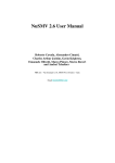
Figure 1.2: Hybrid automaton for a single tank
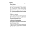
1.4
Running example: Three-tank model
We will illustrate the main features of H Y DI modeling a set of communicating tanks.
The model is an extension of the model presented in [CMT11b].
The tank controls if the level of water increases or decreases opening an output
valve. However, after the output valve has been opened, it must elapse a minimum
amount of time (M) before it can be opened again. When the level of water in a tank
reaches its maximum capacity (C) and the output flow cannot be opened, the tank is
full.
Figure 1.2 shows the hybrid automaton of a single tank.
A tank keeps the level reached by the water in the continuous variable level (l in
the figure). The tank automaton has four location: empty, emptying, filling, full.
• empty: the tank is empty.
• emptying: the level of water decreases.
• filling: the level of water increases.
• full: the tank is full.
A stopwatch variable t keeps track of the time elapsed outside the location emptying. t is reset as soon the state emptying is left.
The state may change from emptying to filling if the tank was emptied for at least 23
of its maximum capacity. As soon as the level of water is 0 in the emptying mode, the
mode is changed to empty. Similarly, when the level reaches the maximum capacity of
the tank in the filling mode and the timer t < M , the mode changes to full. When the
tank is in the empty state it can go to the filling state. The transitions to the emptying
5
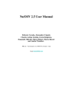
Figure 1.3: Two tank model
state are enabled only if the timer t is greater than the minimum time required between
two emptying operations (M).
We are interested in a model with multiple tanks, connected to the same stream of
water. Figure 1.3 illustrates the two tank model.
Since the input flow of the tanks is the same, when a tank is full the input flow of
the other tanks increases. The goal of the system is to avoid a situation where all the
tanks are full. Thus, when a tank is full, the other tanks increase their output flow to
get rid of the water in excess.
The level of water changes depending on the current location of the tank and also
on the current configurations of the other tanks. For the simple case with two tanks,
when the other tank is full the input flow is doubled. Conversely, when the other tank
is not full anymore, the input flow is halved. Analogously, also the output flow is
doubled/halved to avoid that all the tanks becomes full.
For example, in the two-tank model if a tank is in the full location and the other
is in the emptying location, the value of the level variable in the other tank evolves
according to the differential equation 1̇ = −20. Instead, if a tank is not full, the
differential equation is 1̇ = −10.
Each tank communicates through a synchronization when it becomes full/empty to
the other tanks. Thus, a tank does not know the level of water contained in the other
tanks. On each synchronization, a tank becomes full or not full and thus the input and
output flow of the other tanks change accordingly.
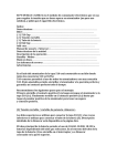
We used the term “location” to describe the model of a single tank. This term
identifies a discrete state of an hybrid automaton (i.e. a node in the graph). In the case
of a single tank, we had four locations empty, emptying, filling, full. We will refer to
this set of values as “control modes” of the tank. In the case of multiple tanks, we have
a location for each possible combination of “control modes” and number of full tanks.
Figure 1.4 shows the hybrid automaton in the case of two tanks.
In the rest of the tutorial, we will focus on a model with three tanks. The model is
a trivial extension of the two-tank model with the addition of another automaton. We
focus on a model with three automaton mainly to show the synchronization features
of the H Y DI language. Moreover, this will also shows a modeling advantage of the
symbolic representation over the explicit representation. Note that every tank added
to the model increases the number of locations and the number of transitions to the
explicit automaton representation.
6
unf illedt2
unf illedt2
f illedt2
f illedt2
start
start
hempty, 0i
l˙ = 0
ṫ = 1
l=0
τ ∧ l = 0 ∧ t := 0
hemptying, 0i
l˙ = −10
ṫ = −1
l ∈ [0, C]
0≤t
τ ∧t≥M
τ
hf illing, 0i
l˙ = 10
ṫ = 1
l ∈ [0, C]
τ ∧l ≤
hempty, 1i
l˙ = 0
ṫ = 1
l=0
τ ∧t≥M
unf illed ∧ tτ≥ M
C
3
∧ t := 0
hf ull, 0i
l˙ = 0
ṫ = 1
l=C
t≤M
τ ∧ l = 0 ∧ t := 0
hf illing, 1i
l˙ = 20
ṫ = 1
l ∈ [0, C]
f illed ∧ l = capacity
τ ∧l ≤
unf illed ∧ t ≥ M
C
3
∧ t := 0
f illed ∧ l = capacity
start
f illedt2
unf illedt2
f illedt2
unf illedt2
Figure 1.4: Hybrid automaton for the two tank example.
7
hemptying, 1i
l˙ = −20
ṫ = −1
l ∈ [0, C]
0≤t
hf ull, 1i
l˙ = 0
ṫ = 1
l=C
t≤M
Chapter 2
H Y DI module definition
In this section we describe the definition of a process type in H Y DI. We show the
instantiation of the process type in a network in the Section 3. To ease the presentation
of the main H Y DI constructs, we provide a step-by-step definition of the tank process
type when there are no other tanks in the network. In this case, the tank does not keep
the number of the other tanks in the network which are full. Later in this section we
will extend this module in the case of three tanks.
Also, we will show the main differences between the syntax of N U SMV3 and
H Y DI. We will refer to the syntax presented in the N U SMV3 manual [CCCJ+ 12].
A H Y DI process is declared with the MODULE keyword in H Y DI. The syntax of
MODULE is slightly different than the one in the N U SMV3 language. In particular, the
elements of the module declaration definition for a H Y DI process are:
module_element ::
var_declaration
| ivar_declaration
| frozenvar_declaration
| event_declaration
| define_declaration
| constants_declaration
| assign_constraint
| trans_constraint
| flow_constraint
| init_constraint
| urgent_constraint
| invar_constraint
| invar_specification
| ltl_specification
We parametrize the tank module with three parameters: the initial level of water,
the maximum capacity and the minimum time between two emptying of the tank.
MODULE Tank(init_level, C, M)
2.1
Variable declaration
The state space of the tank system is determined by its control mode (empty, emptying,
filling, full), the current water level and the total time passed from the last emptying
8
operation. The state space of a system is defined by its state variables (i.e. the variables
declared in the VAR section). In H Y DI we differentiate discrete and continuous variables. Intuitively, the first type of variables define the locations of an hybrid automaton,
while the second type of variables define the continuous variables of an hybrid automaton.
2.1.1
Discrete variables
The control mode is the discrete component of the tank system. A discrete state variable
is declared with the VAR keyword. In the Tank module we declare the control variable:
VAR
control: {empty, emptying, filling, full};
control is an enumerative variable which keeps track of the current control mode of
the tank.
A variable is discrete if its associated type is discrete. All the types, except from
the continuous type, are discrete (e.g. boolean, real, enumerative types, . . . are
discrete types).
2.1.2
Continuous variables
The continuous variables are state variables declared using the type continuous.
Only state variables (i.e. variables declared in the VAR declaration) may have the
continuous type (e.g. an input variable, declared in the IVAR section, cannot be
continuous). A continuous variable is treated as a discrete variable (i.e. it can be used
as a state variable) in the INIT, INVAR, TRANS, ASSIGN declarations. Moreover, when
the (physical) time in the system elapses, all the continuous variables will change their
value according to a differential equation (defined in the FLOW declarations). This is
explained in detail in the Section 2.5.2. The tank keeps the current level of water and
the time elapsed from the last emptying operation.
VAR
level: continuous;
time_out_empty : continuous;
A continuous variable may be used in all the expressions, except for the expressions in the FLOW declaration, as a real variable. All the type checking rules that are
applied to a real variable are applied also to a continuous variable.
2.2
Event declaration
Each automaton in a network communicates using the synchronization mechanism:
two automata will take a transition at the same time (i.e. synchronize) if the transition
is labelled with the same symbol.
Each H Y DI process declares its set of symbols (alphabet) used to label transitions
with the EVENT declaration. In the case of a single tank there is no need of adding
the EVENT declaration, since there are no synchronizations. However, declare the set
of symbols and we will use them to define the transitions of the system. The EVENT
declaration is defined as a comma separated list of values:
event_declaration :: EVENT event_decl_body ;
event_decl_body ::
9
symbolic_constant
| symbolic_constant :: event_decl_body
The set of symbol in the tank model is:
EVENT filled, unfilled, tau;
When defining a transition (Section 2.5) the user may specify the event that labels
it.
2.3
Initial condition
The initial condition of the system is specified using the INIT declarations. The initial condition is a state expression which may predicate over both discrete and continuous variables (see the grammar rule init constrain in the N U SMV3 manual [CCCJ+ 12] for details).
In the tank model the continuous variable level and t are initialized to 0. The
initial value of the level is the input parameter init level. Note that, depending on
the initial level of water, the system should be in different initial locations. However,
we do not want the system to be in the location full in the initial state, since in that
case the other tanks would not known it (i.e. there would be no synchronization).
The initial condition of the tank is:
INIT
control != full & level = init_level & t = 0
2.4
Invariant condition
The INVAR declarations define constraints that must be satisfied in all the states of the
system. The invariant declaration is a state expression which may predicate over both
discrete and continuous variables (see the grammar rule invar constrain in the
N U SMV3 manual [CCCJ+ 12] for details). When encoding an hybrid automaton in
H Y DI, the invariants on the locations of the automaton are encoded as INVAR.
Since H Y DI is symbolic, we can specify a constraint that holds for a set of states.
For example, the invariants that limit the bounds of the level variable must hold in all
the states of the system:
INVAR 0 <= level & level <= C
We can easily model the case where the invariant holds only in a location. Examples
of these invariants are the one in the empty and full locations:
INVAR
(control = empty -> level = 0) &
(control = full -> level = C)
Note that the invariant holds in every state of the system and also when the time in
the system elapses. For example, suppose to have the following invariant:
INVAR control = filling -> (t <= 5 | t >= 6)
t is a continuous variable which just counts the time spent outside the emptying location. The invariant which requires that (t <= 5 | t >= 6) never holds: since
the real time of the system evolves continuously, also t evolves continuously, and thus
there cannot be the “hole” between 5 and 6.
10
It is not sound to write non-convex invariants like t <= 5 | t >= 6. If there is
the need to model such invariants, one can always split the discrete location in two
locations. In one location there will be the invariant t <= 5 and in the other there will
be the invariant t >= 6. Then, there should be some discrete transitions between the
two locations.
2.5
Transitions
H Y DI differentiates two kind of transitions: discrete and continuous.
2.5.1
Discrete transitions
A discrete transition is specified using the TRANS declarations. The syntax of a TRANS
declaration in H Y DI is the same used in N U SMV3, with the exception of the EVENT
identifier, which can be used as an an input variable with an enumerative type.
Each discrete transition taken by a system modeled in H Y DI is labelled with a
symbol defined by the set of events (EVENT declaration). The user may constrain a
specific transition to be labelled with a specific symbol.
A straightforward modelling strategy to encode the transition of an hybrid automaton in H Y DI is to enumerate all the transitions.
Each transition is identified by a source location, a destination location, a guard, a
label, and a set of effects on the continuous variables. For example, in the single tank
hybrid automaton there is a transition from the location emptying to the location empty
with guards l = 0 and effects on the continuous variable t := 0. In H Y DI, we may
encode the source and destination locations with predicates on the control variable:
control = emptying & next(control) = empty
The guard requires that the level variable is equal to 0:
level = 0
The effect of the transition is to set t = 0, while l does not change. Since in H Y DI
all the state variables which are not constrained in a transition will change their value
non-deterministically, we are also forced to explicitly encode the fact that level does
not change:
next(level) = level & next(t) = 0
The conditions which enforce a variable to not change are called frame conditions.
The encoding of the whole transition is:
control = emptying & next(control) = empty & level = 0 &
next(level) = level & next(t) = 0
If all the transitions are encoded in this way, the resulting TRANS constraint will be:
TRANS
(EVENT = tau & control = empty & next(control) = filling &
next(level) = level & next(t) = t) |
(EVENT = tau & control = emptying & level = 0 & next(control) = empty &
next(level) = level & next(t) = 0) |
(EVENT = tau & control = emptying & 3 * level <= C & next(control) = filling &
next(level) = level & next(t) = 0) |
(EVENT = tau & control = filling & t >= M & next(control) = emptying &
next(level) = level & next(t) = 0) |
(EVENT = filled &
control = filling & level = C & next(control) = full &
11
next(level) = level & next(t) = t) |
(EVENT = full &
control = full & t >= M & next(control) = emptying &
next(level) = level & next(t) = t)
The formula in the TRANS constraint encodes the enumeration of all the possible discrete transitions in the model. On models where the discrete state space is more complex (i.e. there is more than one discrete state variable) the enumeration may be cumbersome.
Another way to model the discrete transitions is to enumerate the symbols of the
EVENT variable, and a disjunction of all the transitions labeled with a give event:
(EVENT = tau ->
(
(control = empty & next(control) = filling &
next(level) = level & next(t) = t)
|
(control = emptying & level = 0 & next(control) = empty &
next(level) = level & next(t) = 0)
|
(control = emptying & 3 * level <= C & next(control) = filling &
next(level) = level & next(t) = 0)
|
(control = filling & t >= M & next(control) = emptying &
next(level) = level & next(t) = 0)
)) &
(EVENT = filled ->
control = filling & level = C & next(control) = full &
next(level) = level & next(t) = t
) &
(EVENT = full ->
control = full & t >= M & next(control) = emptying &
next(level) = level & next(t) = t
)
A common source of error is to unspecify the behaviors of the system, not considering
some conditions. For example, suppose that the last implication in the previous declaration of the TRANS condition is missing. In that case, from all the possible states of
the system there exists a transitions labelled with full to all the other possible states
of the system.
The symbolic representation of all the discrete transition of the tank module enable
a more concise specification:
TRANS
-- Filling and unfilling
(EVENT = filled <-> (control = filling & next(control) = full)) &
(EVENT = filled -> t < M) &
(EVENT = unfilled <-> (control = full & next(control) = emptying)) &
-- Transitions from emptying
(control = emptying -> next(control) != full) &
((control = emptying & next(control) = filling) -> (3 * level <= C)) &
-- Transitions from filling
(control = filling -> next(control) != empty) &
(control = empty -> next(control) != emptying) &
-- Reset and frame conditions on the continuous variables
next(level) = level &
(
-- The stopwatch is reset only when exiting the emptying control
12
case
control = emptying & next(control) != emptying : next(t) = 0;
TRUE : next(t) = t;
esac
)
Note the encoding of the frame condition on the continuous variables. The frame
condition for level just ensures that the variable never changes its value in all the
transitions, while the t variable is reset only when the location after the transition is
emptying.
Also, there is no explicit labelling of the transitions labelled with tau. This is due
to the fact that the other two values of the EVENT variables, filled and unfilled,
labels only the transitions from filling to full and from full to emptying (note
the use of the “if and only if” operator).
2.5.2
Continuous transition
The time in the system elapses by means of continuous transitions. The execution
of an hybrid automaton alternates discrete and continuous transitions (i.e. the system
performs some computation steps and the time elapses between them). The continuous
transitions are specified using the FLOW declaration. The FLOW declaration defines
a constraint over the state variables at the current state and the first derivative over
time of the continuous variables. Thus, the next operator cannot be used in a FLOW
declaration.
During a continuous transitions the value of all the discrete variables does not
change and the value of the all the continuous variables changes depending on the
amount of time elapsed and the flow condition. For example, suppose that the system
is in the location filling of the tank automaton, l = 10 and t = 3. In that location the
flow condition for l and t is 1̇ = 10 and 1̇ = 1. After 5 seconds the new value of l will
be 60 and t = 8. It is easy to see that t just counts the time elapsed since its derivative
is 1. The value of l instead increases faster than the elapsed time, since its derivative is
10.
In a FLOW declaration the user specifies the first derivative of a variable using the
der operator. The operator is unary and its argument must be a continuous variables.
Then, this operator is used in a predicate to constrain the value of the derivatives. For
example, one may express the fact that the value of the derivative of level is not fixed,
but takes a value in the range [10, 20]:
10 <= der(level) & der(level) <= 20
Different location of the automaton may have different flow conditions. This is
expressed in H Y DI using the discrete variables in the FLOW condition. For example,
the FLOW condition of the location filling may be written as:
FLOW
control = filling -> (der(level) = 10 & der(t) = 1);
If there are no constraints on the derivative of a continuous variable (e.g. suppose
that the system does not specify it for some locations), then the variable may change
arbitrarily during the continuous transition.
The FLOW condition for the one-tank automaton may be specified as follows:
FLOW
(control = emptying -> der(level) = -10) &
(control = filling -> der(level) = 10) &
13
-- The level does not change in the empty or full control
((control = empty | control = full) -> der(level) = 0) &
-- t counts the time outside the empty control
(
case
control = emptying : der(t) = -1;
TRUE : der(t) = 1;
esac
)
The syntax of the predicates used in the predicate over the first-derivatives (e.g.
der(level) <= 10) is limited. The predicate:
• can contain only constants or the der operator over continuous variables (i.e. it
cannot contain discrete or continuous variables not in the der operator).
• the continuous variables may be used only in the scope of the der operator.
• the expressions in the predicate must be linear.
An expression is linear if it is a linear combination of derivatives and constant coefficient. For example, the expression:
3 * der(level) + 2 * der(t) <= 5
is linear, while the expression:
der(level) * der(t) <= 5
is not, since it multiplies two der operators.
2.6
Urgent conditions
In some cases some discrete transitions have to be taken immediately, without that
some time elapses.
For example, in the empty location time should not elapse and the automaton
should switch to the filling location. The automaton definition does not take this
into account.
This can be achieved using the URGENT declaration. The urgent declaration is
an expression on the current state variables, both discrete and continuous. When an
URGENT declaration is true the time cannot elapse (i.e. the system cannot do a continuous transition). Thus, when a URGENT condition is true, the system is forced to take a
discrete transition.
The tank model has the following urgent constraints:
URGENT control = empty
Note that a URGENT declaration may be modeled using a clock variable and an an
invariant condition. The clock is reset to 0 entering the location and the invariant in the
location ensures that the clock must be less or equal than 0. Thus, time cannot change.
2.7
Submodules
The module may instantiate submodules, as in N U SMV3. Each instance of a submodule will run synchronously with the process (i.e. H Y DI does not allow to declare a
hierarchy of asynchronous processes). Note that the EVENT is only declared in the
14
process module, and not in its sub-instance. In order to access this variable in the
subinstance EVENT has to be passed as a parameter.
2.8
Reserved keywords
Some keywords are reserved in the H Y DI language and thus cannot be used as identifiers. The reserved keywords are: EVENT, delta, time, timed, stutter.
2.9
Three-tanks model
We extend the one-tank model to three-tanks.
In a network of multiple tanks we have this additional requirements:
• The tank must keep the number of the other full tanks in the network.
• The tank must synchronize with each other tank of the network to know when
they get full or not full.
• the tank has different flow conditions in the emptying and filling control
modes, since the tank will fill or empty depending also on the number of full
tanks in the network.
The tank module changes as follows. We add a variable which keeps track of the
number of filled tanks in the network:
-- number of the other filled tanks
VAR filled_tanks : 0 .. 2;
Since all the tanks will not be in the full control mode in the initial state, we add the
constraint:
INIT filled_tanks = 0;
We add 4 additional symbols to the EVENT variable, 2 for each other tanks in the
network:
EVENT filled, unfilled, tau,
filled_tank1, filled_tank2,
unfilled_tank1, unfilled_tank2;
We have some additional transitions which changes the number of full tanks in the
network on synchronization. When another network becomes full, the number of full
tanks must increase. Instead, when a tank is not full anymore, the number of full tanks
must decrease. We also add a DEFINE declaration, sync other tanks to express the
predicate which is true in the case a synchronization happens.
-- SYNC with other tanks
-- sync_other_tanks is true iff the current event is a synchronization
DEFINE sync_other_tanks :=
EVENT in {filled_tank1, filled_tank2, unfilled_tank1, unfilled_tank2};
TRANS
-- when a the tank is full, the number of filled tanks is increased
(EVENT in {filled_tank1, filled_tank2} <->
next(filled_tanks) = filled_tanks + 1) &
-- when a tank is not full anymore, the number of the filled tanks is
-- decreased
(EVENT in {unfilled_tank1, unfilled_tank2} <->
next(filled_tanks) = filled_tanks - 1)
15
Then, we have to ensure that the number of filled tanks does not change on the transitions which are not labelled with a synchronizing event:
-- the filled_tanks number does not change on other events
((! sync_other_tanks) -> next(filled_tanks) = filled_tanks)
We should add the frame conditions for the discrete variable control for these additional transitions:
TRANS
-- the control does not change if other tanks are full
(sync_other_tanks -> next(control) = control)
Finally, we encode the different FLOW conditions. Note that in this case we change
the specification of the flow condition of the tank and we do not just add other declarations to the model.
FLOW
-- The water flow depends on the emptying/filling and on the status of
-- the other tanks.
(control = emptying ->
(filled_tanks = 0 -> der(level) = -10) &
(filled_tanks = 1 -> der(level) = -15) &
(filled_tanks = 2 -> der(level) = -30)
) &
(control = filling ->
(filled_tanks = 0 -> der(level) = 10) &
(filled_tanks = 1 -> der(level) = 15) &
(filled_tanks = 2 -> der(level) = 30)
)
Figure 2.9 shows the complete H Y DI module for the three-tank example.
16
-- init_level: initial level of water in the tank.
-- C: maximum capacity of the tank.
-- M: minimum time required outside the empty state.
MODULE Tank(init_level, C, M)
EVENT filled, unfilled, filled_tank1, filled_tank2,
unfilled_tank1, unfilled_tank2, tau;
VAR
control: {empty, emptying, filling, full};
filled_tanks : 0 .. 2;
level: continuous;
t : continuous;
INIT
control != full & filled_tanks = 0 & level = init_level & t = 0
INVAR
(0 <= level & level <= C) & t >= 0 &
(control = empty -> level = 0) & (control = full -> level = C)
DEFINE sync_other_tanks := ! (EVENT in {filled, unfilled, tau});
TRANS
(EVENT in {filled_tank1, filled_tank2} <->
next(filled_tanks) = filled_tanks + 1) &
(EVENT in {unfilled_tank1, unfilled_tank2} <->
next(filled_tanks) = filled_tanks - 1) &
(sync_other_tanks -> next(control) = control) &
((! sync_other_tanks) -> next(filled_tanks) = filled_tanks) &
(EVENT = filled <-> (control = filling & next(control) = full)) &
(EVENT = filled -> t < M) &
(EVENT = unfilled <-> (control = full & next(control) = emptying)) &
(control = emptying -> next(control) != full) &
(control = filling -> next(control) != empty) &
(control = empty -> next(control) != emptying) &
((control = emptying & next(control) = filling) -> (3 * level <= C)) &
( case
control = emptying & next(control) != emptying : next(t) = 0;
TRUE : next(t) = t;
esac
) & next(level) = level;
URGENT control = empty;
FLOW
(control = emptying ->
(filled_tanks = 0 -> der(level) =
(filled_tanks = 1 -> der(level) =
(filled_tanks = 2 -> der(level) =
) &
(control = filling ->
(filled_tanks = 0 -> der(level) =
(filled_tanks = 1 -> der(level) =
(filled_tanks = 2 -> der(level) =
) &
((control = empty | control = full)
(control = emptying -> der(t) = -1)
-10) &
-15) &
-30)
10) &
15) &
30)
-> der(level) = 0) &
& (control != emptying -> der(t) = 1)
Figure 2.1: H Y DI definition of the three-tanks process
17
Chapter 3
Network of processes
This section describes the features of the H Y DI language used to define a network of
processes.
3.1
Overview
A network is composed by a set of processes which run asynchronously and that communicates using synchronization constraints. The synchronization mechanism works
as follows:
• Each process declares a specific enumerative variable, EVENT. The set of values
of EVENT is called alphabet. The symbols of the alphabet are used to label the
transitions of the process.
• The synchronization constraints specify when processes must take a transition
at the same step. In particular, in H Y DI a synchronization constraint is defined
between a pair of processes, and binds a symbol of one process with a symbol
of the other process. The synchronization constraint is such that when one of
the processes performs a transition labelled with the symbol specified in the synchronization, also the other process must perform a transition labelled with the
symbol of the synchronization.
In the following, we describe the instantiation of the network and the definition of
the synchronization constraints.
3.2
Process Instantiation
The network of processes is instantiated in the main module.
In N U SMV, N U SMV3 and H Y DI the module named main has a specific semantic, since it is the module which defines the entire system. As opposed to N U SMV
and N U SMV3, in H Y DI the main module may contain only the instantiation of the
processes and the synchronization constraints.
The syntax allowed in the main module is restricted to:
module_element ::
var_declaration
18
|
|
|
|
|
sync_constraint
define_declaration
constants_declaration
invar_specification
ltl_specification
In practice, the main module can declare only instances of processes, constants, synchronization constraints and specifications.
The processes are instantiated declaring a state variable that has as type the name of
the H Y DI module which defines the process. The network of the three-tank example
is instantiated as follows:
VAR
tank1: Tank(100, 150, 10);
tank2: Tank(100, 150, 1);
tank3: Tank(100, 150, 1);
3.3
Synchronization constraints
The synchronizations are defined using the SYNC constraint:
sync_constraint ::
SYNC variable_identifier, variable_identifier
EVENT constant, constant
| SYNC variable_identifier, variable_identifier
EVENT constant, constant CONDITION condition_expression
condition_expression ::
next_expression
| next_expr, next_expr
A SYNC constraint involves two processes and specifies two “synchronizing”
events. One of the events belongs to the alphabet of the first process involved in the
synchronization, while the other belongs to the other process. The SYNC constraint
imposes that when one of the processes in the synchronization performs a transition
labelled with the synchronizing event, also the other process must perform a transition
labelled with its synchronizing event. For example, the SYNC constraint:
SYNC proc1, proc2 EVENT event1,event2;
forces that if proc1 performs a transition labelled with event1 also proc2 will move
on a transition labelled with event2 and vice-versa.
This can be seen in the simple example of the gates shown in Section 1. In that
example the synchronization constraints where:
SYNC gate1, gate2 EVENTS open, open;
SYNC gate1, gate2 EVENTS close, close;
In this case, they impose that gate1 performs a transition labelled with open if and
only if gate2 performs a transition labelled with open. There is a similar constraint for
the event close. Note that, in general, the name of the two events in a SYNC constraint
can be different (i.e. the label of the first and the second process may be different).
We will refer to all the events of a process that are involved in a synchronization as
shared events. All the other events of the process are called local events.
In the three-tank model each tank synchronizes with another tank on its full and
unfull events. Also, each tank must synchronize with all the other tanks when they
19
are full or not full. We may encode these synchronization between the tank1 and
tank2 as follows:
SYNC tank1, tank2 EVENTS filled, filled_tank1;
SYNC tank1, tank2 EVENTS unfilled, unfilled_tank1;
However, now tank2 will know when tank1 is full, but tank1 does not. Thus, we
must add the symmetric synchronization constraints:
SYNC tank2, tank1 EVENTS filled, filled_tank1;
SYNC tank2, tank1 EVENTS unfilled, unfilled_tank1;
At this point, tank3 does not communicate with any other tank. We may synchronize it with the tank1:
SYNC
SYNC
SYNC
SYNC
tank1,
tank1,
tank3,
tank3,
tank3
tank3
tank1
tank1
EVENTS
EVENTS
EVENTS
EVENTS
filled, filled_tank1;
unfilled, unfilled_tank1;
filled, filled_tank2;
unfilled, unfilled_tank2;
A semantic point about the H Y DI synchronization is that they are transitive. Consider the following synchronization constraints on a set of events p1, p2, p3:
SYNC p1, p2 EVENTS event1, event2;
SYNC p2, p3 EVENTS event2, event3;
In this situation, by transitivity, p1 will synchronize with p3 on the event event1 (the
event for p3 will be event3). This is a consequence of the semantics of the SYNC
constraint.
Thus, in the three-tank model, since we have:
SYNC tank1, tank2 EVENTS filled, filled_tank1;
SYNC tank1, tank3 EVENTS filled, filled_tank1;
We have also that:
SYNC tank2, tank3 EVENTS filled_tank1, filled_tank1;
This is also the main motivation to distinguish in each tank the events
filled tank1 and filled tank2 (and similarly for the unfilling). Suppose that
these two events are not disjoint, and there is only one event filled tank. Among
the synchronization of the system, we would also have the following constraints:
...
SYNC tank1, tank2 EVENTS filled, filled_tank;
...
SYNC tank3, tank2 EVENTS filled, filled_tank;
By the transitivity constraints, we can infer the following SYNC constraint:
SYNC tank1, tank3 EVENTS filled, filled;
Obviously, it is not correct that tank1 and tank3 always become full at the same time.
The transitivity of constraints is a common source of mistake, and must be understood to create sound models in H Y DI. Also, as a special instance of the transitivity
constraint mechanism, it is not possible to synchronize the same event of a process with
two different events of another process. The synchronization constraints would be:
SYNC p1, p2 EVENTS a,b;
SYNC p1, p2 EVENTS a,c;
So, by the transitivity constraint we would also have that if p1 moves on a p2 must
move at the same time both on b and c. Also in this case, the solution is to duplicate
the event.
The synchronization constraints for the three-tanks model are:
20
-- Synchronizations of tank1
SYNC tank1, tank2 EVENTS filled, filled_tank1;
SYNC tank1, tank2 EVENTS unfilled, unfilled_tank1;
SYNC tank1, tank3 EVENTS filled, filled_tank1;
SYNC tank1, tank3 EVENTS unfilled, unfilled_tank1;
-- Synchronizations of tank2
SYNC tank2, tank1 EVENTS filled, filled_tank1;
SYNC tank2, tank1 EVENTS unfilled, unfilled_tank1;
SYNC tank2, tank3 EVENTS filled, filled_tank2;
SYNC tank2, tank3 EVENTS unfilled, unfilled_tank2;
-- -- Synchronizations of tank3
SYNC tank3, tank1 EVENTS filled, filled_tank2;
SYNC tank3, tank1 EVENTS unfilled, unfilled_tank2;
SYNC tank3, tank2 EVENTS filled, filled_tank2;
SYNC tank3, tank2 EVENTS unfilled, unfilled_tank2;
3.3.1
Message passing
A common mechanism used in the presence of synchronizations is message-passing.
In message-passing, the processes involved in the synchronization may exchange the
value of some variables. This extends the power of synchronizations, which can be
used to exchange data variables between processes.
Message-passing is achieved using the CONDITION expression of the SYNC constraint. In its general form, the CONDITION expression is an expression which predicates over the variables of both the processes involved in the synchronization and may
contain the next operator. In order to avoid the name clash of the variables with the
same name in the two processes, all the symbols declared in a process must be prefixed
by the name of the process instance and a dot (e.g. the variable v in the process p1 is
written as p1.v).
A SYNC constraint with the CONDITION expression forces two process to synchronize on the synchronization events, as without CONDITION, but imposes also some
additional constraints which limits when the synchronization happens.
We explain this mechanism through an example. The three-tank model still does
not exploit the CONDITION feature. Thus, we extend it adding a process which monitors the value of the variable t of each tank when the tank becomes full, and keeps as
internal state a sum of these values.
MODULE monitor
EVENT filled;
VAR total_t : real;
IVAR t_at_full : real;
INIT total_t = 0
TRANS
next(total_t) = total_t + t_at_full
We instantiate the monitor with a synchronization constraint with tank1:
VAR monitor1 : monitor;
SYNC tank1, monitor1 EVENTS filled, filled
CONDITION (tank1.t = monitor1.t_at_full);
In a nutshell, this constraint:
21
MODULE
VAR
tank1:
tank2:
tank3:
main
Tank(100, 150, 10);
Tank(100, 150, 1);
Tank(100, 150, 1);
-- Synchronizations of tank1
SYNC tank1, tank2 EVENTS filled, filled_tank1;
SYNC tank1, tank2 EVENTS unfilled, unfilled_tank1;
SYNC tank1, tank3 EVENTS filled, filled_tank1;
SYNC tank1, tank3 EVENTS unfilled, unfilled_tank1;
-- Synchronizations of tank2
SYNC tank2, tank1 EVENTS filled, filled_tank1;
SYNC tank2, tank1 EVENTS unfilled, unfilled_tank1;
SYNC tank2, tank3 EVENTS filled, filled_tank2;
SYNC tank2, tank3 EVENTS unfilled, unfilled_tank2;
-- -- Synchronizations of tank3
SYNC tank3, tank1 EVENTS filled, filled_tank2;
SYNC tank3, tank1 EVENTS unfilled, unfilled_tank2;
SYNC tank3, tank2 EVENTS filled, filled_tank2;
SYNC tank3, tank2 EVENTS unfilled, unfilled_tank2;
Figure 3.1: H Y DI definition of the main module of the tree-tanks model
• forces tank1 to synchronize with monitor1 on the filled event.
• in order to synchronize, it must be the case that the value of t in the tank1
process is equal to the value of the variable monitor1.t at full.
Thus, this constraint has the effect to exchange the value of the t variable between the
two processes.
In this case, monitor1.t at full is an input variable of monitor1 which is not
constrained at all. For this reason, all the transitions that tank1 performs were possible
before the new SYNC constraint are still not blocked. Suppose that in the definition of
the monitor module we add:
TRANS t_at_full >= 5
With this constraint, the synchronization between the tank and the monitor is not possible if t at full is less than 5.
Note that the CONDITION expression does not change the fact that a process move
on a shared event if and only if also the processes which synchronize with it moves on
shared events. In the tank example with the constraint t at full >= 5, it is not the
case that tank1 moves on the filling event on its own if t at full >= 5 does not.
As a syntactic sugar, the CONDITION expression may be also written as couple of
next expressions separated by a comma:
SYNC tank1, monitor1 EVENTS filled, filled CONDITION t, t_at_full;
The first element of the couple is a next expression over the variables of tank1,
while the second element is over the variables of monitor1. Then, the semantic is that
the first element of the couple must be equal to the second element of the couple (in
the case of predicates, there is an if and only if operator).
Figure 3.3.1 shows the main module of the three-tank example.
22
Chapter 4
Language extensions
The original definition of H Y DI was extended to allow the following features:
• Shared variables: a process may access directly variables declared in other processes.
• Explicit scheduler: the user may model different scheduling policy and thus constrain the execution of the asynchronous network of processes.
Note that all these features may limit the set of verification techniques applicable to the
model, as explained in Section 5.
4.1
Shared variables
A widely used mechanism of inter-process communication are shared variables. H Y DI
enables the shared variable mechanism passing parameters during the instantiation of
the process modules. When a process is instantiated it can take as input some parameters. In the three-tank model, all the parameters were constant. However, it is also
possible to use the variable of another process as an actual parameter. In this way a
process is able to access the variable in another process.
As an example we define an additional module which tracks the level of water in
all the three tanks and that goes to an alarm state when the sum of all the levels is above
a certain threshold.
MODULE alarm(level1, level2, level3, THRESHOLD)
VAR location : {normal, alert};
DEFINE normal_condition := level1 + level2 + level3 <= THRESHOLD;
DEFINE alert_condition := level1 + level2 + level3 >= THRESHOLD;
INVAR location = normal -> normal_condition
INVAR location = alert -> alert_condition
TRANS location = normal & alert_condition & next(location) = alert;
TRANS location = alert & normal_condition & next(location) = normal;
The process is instantiated using as actual parameters the level variable of the
tanks:
alarm_monitor : alarm(tank1.level, tank2.level,
tank3.level, 400);
23
An important constraint is that shared variables are read only. Thus, a process cannot predicate over the next value of an input parameter. This means that
the alarm monitor process cannot constrain the next value of one of the variables
level1, level2 or level3.
4.2
Explicit scheduler
Several domain specific languages may use a different semantic of asynchronous processes. For example, one may impose an order of execution on the processes with the
policy that a process run when it is his turn to run or it synchronizes with the process
that has the turn to run.
We may encode this scheduler constraints in the main module of an H Y DI program, which thus is enriched as follows:
module_element ::
var_declaration
| ivar_declaration
| frozenvar_declaration
| sync_constraint
| define_declaration
| constants_declaration
| assign_constraint
| trans_constraint
| init_constraint
| invar_specification
| ltl_specification
This scheduler may be encoded in the three-tanks program:
MODULE
VAR
tank1:
tank2:
tank3:
main
Tank(100, 150, 10);
Tank(100, 150, 1);
Tank(100, 150, 1);
-- definition of the scheduler
VAR turn : {1,2,3};
INIT turn = 1
TRANS
tank1.EVENT != timed ->
next(turn) = case
turn = 1 : 2;
turn = 2 : 3;
-- turn = 3
TRUE : 1;
esac
TRANS
turn = 1 -> tank1.EVENT != tau;
TRANS
turn = 2 -> tank1.EVENT != tau;
TRANS
turn = 3 -> tank1.EVENT != tau;
-- Synchronizations of tank1
SYNC tank1, tank2 EVENTS filled, filled_tank1;
...
24
The scheduler runs synchronously with all the processes in the network and moves
even when the processes perform a continuous transition. This because the scheduler
may also constrain the execution of the system during continuous transitions.
The scheduler may access to the the EVENT variable of all the processes. Moreover,
the scheduler may predicate over the special event name timed, which identifies when
a process is performing a timed transitions.
In the three-tank example the scheduler does not change its state during a continuous transition. However, it was necessary to explicitly handle the continuous transition
case.
25
Chapter 5
Current limitations
The current released version of H Y DI has several limitations.
First, the hybrid automata that can be analyzed are limited to the class of linear hybrid automata [Hen96] and to all its subclasses. This mean mainly that the predicates
which contain the der operator used in the FLOW condition must be a linear combination over the first-derivative operator.
Then, he features used in a H Y DI program may seriously limit the applicability of
some model checking techniques and optimizations.
In particular, some techniques rely on the use of the local-time semantics as opposed to the common global-time semantics. It is not the goal of this document
to describe both semantics, both their details may be found in [BCL+ 10, CMT11a,
CMT11c]. While all the features of the H Y DI language can be used with the globaltime semantics, some of them hinders the use of the local-time semantics. In particular,
all the features described in the section 4 CANNOT be handled with the local-time.
In several cases different modelling choices enables to use the local-time semantics.
For example, sometimes the use of shared-variables may be avoided with the use of
additional events and synchronization constraints.
Also, an optimization called step-semantic, which usually improves the efficiency
of the verification process enabling more processes to move on independent transitions,
cannot be used with the extended version of H Y DI. In the case of shared variables for
example the independence of the transitions cannot be determined anymore (or at least,
it cannot be determined in a cheap way).
26
Bibliography
[BCL+ 10] L. Bu, A. Cimatti, X. Li, S. Mover, and S. Tonetta. Model checking
of hybrid systems using shallow synchronization. In FMOODS/FORTE,
pages 155–169, 2010.
[CCCJ+ 02] R. Cavada, A. Cimatti, E. Olivetti C.A. Jochim, G. Keighren, M. Pistore,
M. Roveri, and A. Tchaltsev. NuSMV 2.1 User Manual, 2002.
[CCCJ+ 12] R. Cavada, A. Cimatti, E. Olivetti C.A. Jochim, G. Keighren, M. Pistore,
M. Roveri, and A. Tchaltsev. NuSMV 3.0 User Manual, 2012.
[CCG+ 02] A. Cimatti, E.M. Clarke, E. Giunchiglia, F. Giunchiglia, M. Pistore,
M. Roveri, R. Sebastiani, and A. Tacchella. NuSMV 2: An OpenSource
Tool for Symbolic Model Checking. In CAV, pages 359–364, 2002.
[CMT11a] A. Cimatti, S. Mover, and S. Tonetta. Efficient scenario verificastion for
Hybrid Automata. In CAV, pages 317–332, 2011.
[CMT11b] A. Cimatti, S. Mover, and S. Tonetta. HYDI: a language for symbolic
hybrid systems with discrete interaction. In EUROMICRO-SEAA, pages
275–278, 2011.
[CMT11c] A. Cimatti, S. Mover, and S. Tonetta. Proving and explaining the unfeasibility of Message Sequence Charts for hybrid systems. In FMCAD,
2011.
[Hen96]
T. A. Henzinger. The theory of hybrid automata. In LICS, pages 278–292.
IEEE CS, 1996.
[McM93]
K. L. McMillan. Symbolic Model Checking. Kluwer Academic, 1993.
27