1
LS-7000 Series User’s Manual
96M11341
User’s Manual
High-speed, High-precision Digital Micrometer
LS-7000 Series
Copyright (c) 2010 KEYENCE CORPORATION. All rights reserved.
11342E 1070-1 96M11341 Printed in Japan
Preface
This instruction manual provides necessary information on the operation and maintenance
of the LS-7000 Series along with precautions. Please read the manual carefully and be
sure you understand the information provided before attempting to install and operate the
LS-7000 Series. Keep this manual handy for future reference.
Please make sure that the end users are provided with this manual.
Symbols
The following symbols are used for the list of precautions to ensure safety and to prevent
personal injury and/or property damage when using the LS-7000 Series.
The following symbols alert you to important messages. Be sure to read these messages
carefully.
DANGER
Failure to follow instructions may lead to death or serious injury.
WARNING
Failure to follow instructions may lead to injury.
CAUTION
Failure to follow instructions may lead to product damage
(product malfunctions, etc.).
Important:
Provides important precautions and restrictions on proper operation.
Note:
Provides additional information on proper operation.
Tips
Reference:
Provides useful information on proper operation.
Provides reference pages.
General precautions
1. No part of this manual may be reprinted or reproduced in any form or by any means
without the prior written permission of KEYENCE CORPORATION.
2. The content of this manual is subject to change without notice.
3. KEYENCE has thoroughly checked and reviewed this manual. Please contact the sales
office listed at the end of this manual if you have any questions or comments regarding
this manual, or if you find an error.
4. KEYENCE assumes no liability for damages resulting from the use of the information in
this manual, item 3 above notwithstanding.
5. KEYENCE will replace any incomplete or incorrectly collated manual.
6. All company names and product names in this manual are registered trademarks or
trademarks of their respective owners.
Safety Precautions
■ General precautions
• At startup and during operation, be sure to monitor the functions and performance of
the LS-7000 Series.
• Take sufficient safety measures to prevent damage to the human body and/or equipment that may be caused if this product should fail to operate properly.
• Do not modify the LS-7000 Series or use it in any way other than as described in the
specifications. Its functions and performance are not guaranteed under said
conditions.
• When the LS-7000 Series is used in combination with other instruments, its functions
and performance may be degraded, depending on the operating conditions and
surrounding environment.
• Do not use the LS-7000 Series for the purpose of protecting the human body.
• Do not expose the LS-7000 Series and peripheral devices to sudden temperature
change, as this may cause condensation.
■ Precautions
WARNING
■ Operation
• Always use the LS-7000 Series at 24 VDC, otherwise a fire,
electric shock or product failure may result.
• Prepare the applicable AC power supply cable if you use LSS11.
• Secure the GND line of the power cable of the AC power
supply stand to protective ground, otherwise an electric shock
or product failure may result.
• Do not disassemble or modify the LS-7000 Series.
This may cause fire or electric shock.
■ When abnormal conditions are encountered
If the following conditions are encountered, immediately turn off
the power. Continuing to use the LS-7000 Series. under abnormal conditions may cause fire, electric shock or equipment
failure.
Contact your nearest KEYENCE sales office for repairs.
• When water or foreign matter enters the controller.
• When the LS-7000 Series. is dropped or the housing is
damaged.
• When the controller produces smoke or an abnormal smell.
96M11341
i
CAUTION
■ Usage
• Be sure to turn off the power to the LS-7000 Series and any
connected devices before connecting or disconnecting the
cables. Otherwise, the camera and connected devices may be
damaged.
• Do not turn off the power while setting a parameter. Otherwise,
the settings may be partially or completely lost.
• Do not block the ventilation slots on the LS-7000 Series and
peripheral devices. A rise in inner temperature may cause
equipment failure.
■ Proper environment and conditions
To use the LS-7000 Series properly and safely, do not install
the LS-7000 Series in locations with the following conditions.
Use of this equipment in an improper environment may cause
fire, electric shock, or equipment failure.
• Locations with high humidity, a large amount of dust, or poor
ventilation
• Locations where the temperature rises excessively due to
direct sunlight, etc.
• Locations where corrosive or flammable gas exists
• Locations where the LS-7000 Series is directly subjected to
vibration or impact
• Locations where water, oil or chemicals may splash the LS7000 Series
• Locations where static electricity is easily built up
■ Countermeasures against Noise
The LS-7000 Series may malfunction or fail to operate due to
noise generated from power lines or high-tension lines. If the LS7000 Series is operated close to such noise sources, use a noise
filter, wire the cable of the LS-7000 Series in an independent
conduit, or locate the LS-7000 Series in an area with proper
insulation from noise.
ii
Note:
■ Influence of Ambient Operating Temperature
Ensure that the ambient operating temperature is constant. A
change in the ambient operating temperature may result in
measurement errors. If the ambient operating temperature
changes by 10°C, it will take approximately 60 minutes for the
interior temperature distribution of the LS-7000 Series to be
uniform.
■ Warming Up
Do not operate the LS-7000 Series for approximately 30 minutes
after it is turned on. The internal circuitry of the LS-7000 Series is
not stable immediately after it is turned on. The measured value
drifts gradually as a result.
■ Influence of Dust and Dirt
A measurement error may result due to dirt, dust, water, or oil in
any of the following cases.
• Cover glass: Blow off the dirt, dust, water or oil on the cover
glass with clean air. If the cover glass is excessively dirty, wipe
the glass with a soft cloth moistened with isopropyl alcohol.
• Target surface: Blow off the dirt, dust, water or oil on the surface with clean air or wipe the surface.
• Intrusion of dirt, dust, water or oil blown or sprayed into optical
sensing area: Install a protection cover or perform air purging.
■ Influence of Vibration
The measured value of an object may fluctuate if the object is
vibrating. If that happens, increase the averaging number. This
will ensure highly accurate measurement.
■ Targets
The measured value of an object may have an error due to the
shape and surface condition. Locate a reference object within the
measuring area and use the calibration function of the LS-7000
Series to correct the error if that happens.
■ Influence of Air Flow
The measured value of an object may fluctuate due to a slow
flow of air. In that case, the following countermeasures are
effective.
• Protect the measuring head with a cover.
• Use a fan to mix the air vigorously between the transmitter and
receiver.
■ Maintenance
Do not wipe the LS-7000 Series with a damp cloth or a cloth
moistened with benzine or paint thinner. This may cause the
discoloration or deformation of the LS-7000 Series. If the LS7000 Series is excessively dirty, use a tightly squeezed cloth
moistened with thin neutral detergent. Then wipe the LS-7000
Series with a soft dry cloth.
■ Precautions for LED
The LS-7010/LS-7030/LS-7070 Measuring Head uses an LED light source. Abide by the
following precautions when using the unit.
• Do not look at the LED light source for a long time.
The LED used as the light source is classified into class 1
CAUTION
according to IEC60825-1 standards. Basically the light beam of
the LED is safe, but do not look at the LED for a long time.
• Do not disassemble the unit.
The unit does not incorporate a mechanism to stop the emission
of the LED when the unit is disassembled. Never attempt to
disassemble the unit, otherwise you will be exposed to LED light.
iii
Precautions for CE Markings
Keyence confirms that the LS-7000 Series meets EC directive requirements. The LS-7000
Series bears CE markings. Keep the following conditions if the LS-7000 Series is used in
European countries.
■ EMC Directives
Keep the following condition so that the LS-7000 Series will satisfy EN61326-1
requirements.
• The power cable and I/O cable connected to the controller are both less than 30m in
length.
• Attach the OP-31973 Clamp-type Ferrite Core to the cable between the controller and
measuring head. The attaching position is as close as possible to the cable end on
the controller side, where the core must be snapped onto the cable to form a one-turn
loop.
Ferrite core
OP-31973
■ Low-voltage Directives
When using the LS-S11 AC Power Supply Stand as a dedicated power supply to the LS7000 Series, keep the following conditions so that the LS-S11 will satisfy EN61010-1
requirements. The LS-S11 satisfies EN60825-1 (LED Class 1) requirements with no
conditions attached.
Environment Conditions
Installation category (Overvoltage category): II (see note 1)
Pollution degree: 2 (see note 2)
Operation and Installation Conditions
• The LS-S11 AC Power Stand is a dedicated power supply for the LS-7000 Series.
Never use the LS-S11 for other purposes.
• When using the LS-7000 Series in European countries, check that the AC power
supply cable satisfies EC directive requirements certified by an authorized third party.
Consult your Keyence representative for the AC power supply cable in detail.
• Before turning the LS-7000 Series on, connect the ground terminal of the AC power
supply cable to the protective ground terminal of the power supply.
• Be sure to use a time lag fuse rated 250 V, 3.15 A for the replaceable fuse of the LSS11.
iv
Note 1:
Installation categories (overvoltage categories) include impulse overvoltage regulations at transient overvoltage levels specified by EC directives.
Installation category II indicates a level where power is provided from fixed
installations, such as distribution panels.
Note 2:
The pollution degree refers to the level of solid, liquid, or gas contamination that
deteriorates the dielectric strength or surface resistance of the LS-7000 Series.
Pollution degree 2 indicates the normal indoor environment (free of non-conductive contamination).
About this Manual
The following section provides information on the configuration of each page of this manual
along with symbols and terms used in this manual.
Page Configuration and Symbols
Chapter 3 Operation Control
Automatic Zero Function
The automatic zero function sets measuring values to zero (0.00000) instantly. This function is convenient for zero-point calibration for a variety of target. Furthermore,
master calibration is possible by using this function in combination with the offset function.
Note:
Tips: Describes
information that will
deepen the user’s
comprehension of
the manual along
with other useful
information.
This function will not be available while the controller is awaiting the result of
measurement, during which the LCD monitor will display “– – –. – – – –.”)
The automatic zero value will not be lost after the LS-7500 Series is turned
off. The automatic zero value for each program will be stored.
Tips
Automatic zero settings are made through the following functional components.
• Control panel
• External terminal
• RS-232C interface
3
■ Control Panel
If a single measuring value is displayed, an
automatic zero setting will be made for the
corresponding OUT number only.
If both measuring values are displayed, an
automatic zero setting will be made for the
selected OUT number on the screen.
1 Press the [ZERO] key once. Automatic
Note: Describes
items that need the
user’s attention in
order to prevent
mistakes in the
operation of the
LS-7000 Series.
HOLD
ZERO
AREA
DISP
zero will be set.
To cancel the setting, press the [ZERO]
key again.
■ External I/O Terminal
Automatic zero will be set by short-circuiting the I/O, ZERO, and COM terminals on the
rear panel of the controller together.
Refer to Section 7 I/O Terminals on page 7-1 for details.
Caution: Indicates
information that, if
not heeded, could
result in relatively
serious or minor
injury, damage to
the LS-7000 Series,
or faulty operation.
CAUTION
Tips
• Do not look at the LED light source for a long time.
The LED used as the light source is classified into class 1
according to IEC60825-1 standards. Basically the light beam of
the LED is safe, but do not look at the LED for a long time
Master Calibration with Offset Function (Automatic Offset Function)
Set the size of a master workpiece to an offset value and make an automatic
zero setting while measuring the master workpiece. Then the size of the
master workpiece will be displayed as an offset value. Refer to 3-3 Measurement of Outer Diameter and Width (with Two Measuring Heads) on page 3-4
for an application example.
Refer to Offset on page 5-43 for the offset function in detail.
3-10
❈ The above page sample is for your reference only. It does not coincide with any of
the actual pages of this manual.
Definition of Terms
This manual uses the following terms.
Term
LS-7000 Series
Controller
Measuring head
Description
Refers to the LS-7001 controller and the measuring head as a set.
Refers to the LS-7001 controller.
Refers to the LS-7010/LS-7030/LS-7070 measuring head.
v
Optimum Measurement Methods
Refer to the following methods, and select the optimum measurement method according to
the type of target.
Measurement of Outer Diameter
of a Round Bar or Wire
D
Measurement of Average Outer
Diameter of Round Bar or Wire
Measurement of Sheet Width
Y
X
L
Measurement of outer diameter and
width (with single measuring head)
(Page 2-2)
Measurement of outer diameter and
width (with two measuring heads in X
and Y directions) (Page 2-3)
Measurement of outer diameter and
width (with two measuring heads for
larger objects) (Page 2-4)
Measurement of Inner
Diameter of a Disc
Measurement of Outer Diameter
and Eccentricity of a Roller
Measuring Robot Movement
and Positioning of LCD Plate
Measurement of inner diameter and
clearance (Page 2-5)
Measurement of Connector
Pins and IC Pins
Measurement of pitch (Page 2-8)
vi
Measurement of outer diameter and
eccentricity (Page 2-6)
Measurement of movement and
positioning (Page 2-7)
Configuration of Manual
Chapter 1
Getting Started
1
Provides information on precautions and necessary preparations
required.
Chapter 2
Easy Setting Guide
2
Provides information on targets and settings for typical applications
respectively.
Chapter 3
Operation Control
3
Provides information on setting control items on the control panel while
the LS-7000 Series is in measurement operation.
Chapter 4
Function Settings
4
Provides information on the overview of program settings and setting
methods.
Chapter 5
Environment Settings
5
Provides information on basic operation settings.
Chapter 6
I/O Terminals
6
Provides information on the specifications of the I/O terminals and
timing charts.
Chapter 7
RS-232C
7
Provides information on how to connect external devices and the
communications function to operate the LS-7000 Series through the
external devices.
Chapter 8
Specifications
8
Provides the specifications, characteristics, and external dimensions of
the LS-7000 Series.
Chapter 9
Troubleshooting
9
Provides information on troubleshooting and error messages.
Appendix
Appendix
Provides a list of options and the index of the manual.
vii
LS-7001 Operation Map
Select the area (See page 3-4)
Press the Up or Down key to
select the area.
AREA
The selected area appears on the
AREA display.
POSITION monitor
The POSITION monitor is lit according to the
position and size of the target.
FOCUS monitor
The FOCUS monitor is lit according
to the distance between the
transmitter and receiver.
To make lit range changes, refer to
page 4-14.
AREA
1
2
POSITION
Program Settings
FOCUS
Area, calibration, output, or option
setting:
PROG
Press the
item with
PROG
FUNC
ESC
key and select the
PRINT
key.
FUNC
ENT
PROG No.
No
Environment setting:
Press the
the
FUNC
PROG
key while pressing
key.
Set item selection:
Press the
or
key.
Program selection
Set item cancellation:
Press the
ESC
key.
Entering set item:
Press the
viii
ENT
key.
Press the Up or Down key.
PROG No.
OUT 1
Tolerance setting (See page 4-50)
OUT 2
HI
Reference value mode
GO
LO
Upper limit setting:
Press the
HI
key.
Reference value setting:
Press the
GO
key.
Lower limit setting:
Press the
LO
key.
TIM
HI
Threshold setting
GO
HI value setting:
Press the
HI
key.
HH value setting:
Press the
HI
key 2X.
LO value setting:
Press the
LO
key.
LL value setting:
Press the
LO
key 2X.
LO
HOLD
Value change while setting
ZERO
Press the key
below the value
flashing.
LO
o.
AREA
DISP
HOLD
LS-7000
ZERO
Hold function (See page 3-5)
Measured value display selection
Press the Up or Down key.
Press the
HOLD
key.
Auto zero function (See page 3-6)
DISP
Measured value display varies
between the reference value mode
and threshold mode for tolerance
setting. (See page 3-2)
Press the
ZERO
key.
To cancel the function, press the
ZERO
key again.
ix
Contents
Safety Precautions .............................................................................................................. i
Precautions for CE Markings ........................................................................................... iv
About this Manual .............................................................................................................. v
Page Configuration and Symbols .................................................................................... v
Definition of Terms .......................................................................................................... v
Optimum Measurement Methods .................................................................................... vi
Configuration of Manual .................................................................................................. vii
LS-7001 Operation Map .................................................................................................. viii
Contents .............................................................................................................................. x
Chapter 1 Getting Started
Outline and Features of LS-7000 Series ....................................................................... 1-2
System Applications ....................................................................................................... 1-3
Package Checks .............................................................................................................. 1-4
LS-7001 ....................................................................................................................... 1-4
LS-7010 ....................................................................................................................... 1-4
LS-7030 ....................................................................................................................... 1-4
LS-7070 ....................................................................................................................... 1-5
LS-C✱✱A ..................................................................................................................... 1-5
LS-S11 ......................................................................................................................... 1-6
Functions and Nomenclature ......................................................................................... 1-7
Controller ..................................................................................................................... 1-7
Measuring Head ........................................................................................................... 1-9
Mounting and Connection ............................................................................................ 1-11
Mounting the Measuring Head ................................................................................... 1-11
Mounting the Controller .............................................................................................. 1-13
Connection ................................................................................................................. 1-17
Turning AC Power Supply Stand On and Off .............................................................. 1-19
Measurement and Setting Overview ........................................................................... 1-20
Resetting to Initial Status ............................................................................................. 1-21
Chapter 2 Easy Setting Guide
Measurement of Outer Diameter and Width (with Single Measuring Head) .............. 2-2
Measurement of Outer Diameter and Width (with Two Measuring Heads) ................. 2-3
Measurement of Outer Diameter and Width
(with Two Measuring Heads for Larger Objects) .......................................................... 2-4
Measurement of Inner Diameter and Clearance ........................................................... 2-5
Measurement of Outer Diameter and Eccentricity ....................................................... 2-6
Measurement of Movement and Positioning ................................................................ 2-7
Measurement of Pitch ..................................................................................................... 2-8
Chapter 3 Operation Control
Selection of Measured Value Display ............................................................................ 3-2
Area Monitor .................................................................................................................... 3-4
Hold Function .................................................................................................................. 3-5
Automatic Zero Function ................................................................................................ 3-6
Panel Lock Function ....................................................................................................... 3-7
Program Changes ........................................................................................................... 3-8
x
Chapter 4 Function Settings
Flow of Program Settings ............................................................................................... 4-2
Default Values and Possible Setting Ranges ............................................................... 4-4
Copying Program Setting Details and Initialization ..................................................... 4-6
Area Settings ................................................................................................................... 4-7
Area Selection .............................................................................................................. 4-9
Focus Monitor ............................................................................................................ 4-14
Area Check ................................................................................................................ 4-15
Difference Check ........................................................................................................ 4-16
Function Output Selection .......................................................................................... 4-17
Change of Edge Detection Threshold ........................................................................ 4-18
Calibration Settings ...................................................................................................... 4-20
Calibration Type Selection ......................................................................................... 4-23
Logic Calibration Settings .......................................................................................... 4-23
Two-point Calibration Settings ................................................................................... 4-25
One-point Calibration Settings ................................................................................... 4-26
Initialization of Calibration .......................................................................................... 4-26
Output Settings ............................................................................................................. 4-28
Area Calculation ......................................................................................................... 4-30
Number of Averaging Measurements ......................................................................... 4-31
Measuring Mode ........................................................................................................ 4-33
Offset ......................................................................................................................... 4-43
Analog Output Settings .............................................................................................. 4-44
Comparator Output Setting ........................................................................................ 4-47
Tolerance (LIMIT) Settings ........................................................................................... 4-50
Limit Range ................................................................................................................ 4-50
Limit Settings ............................................................................................................. 4-51
Hold Value Elimination ............................................................................................... 4-52
Option Settings ............................................................................................................. 4-54
Tolerance Mode (LIMITS)........................................................................................... 4-56
Timing Mode .............................................................................................................. 4-56
Display Unit ................................................................................................................ 4-57
Minimum Display Unit ................................................................................................ 4-58
I/O Mode .................................................................................................................... 4-59
Units, Default Minimum Values, and Setting Ranges ................................................. 4-60
Chapter 5 Environment Settings
Possible Environment Settings ...................................................................................... 5-2
Default Settings ............................................................................................................ 5-2
Changing Environment Settings .................................................................................. 5-3
Flow of Environment Setting Display ........................................................................... 5-4
Details of Environment Settings .................................................................................... 5-5
Program ....................................................................................................................... 5-5
RS-232C ...................................................................................................................... 5-7
Head .......................................................................................................................... 5-10
Beep ........................................................................................................................... 5-12
Panel Lock ................................................................................................................. 5-13
xi
Chapter 6 I/O Terminals
Nomenclature and Functions of I/O Terminals ............................................................. 6-2
Terminal Block .............................................................................................................. 6-2
Connector I/O ............................................................................................................... 6-4
Functions ..................................................................................................................... 6-7
Electrical Specifications ............................................................................................... 6-9
Timing Chart .................................................................................................................. 6-11
Chapter 7 RS-232C
Specifications .................................................................................................................. 7-2
Communication using Serial Commands ..................................................................... 7-4
Connecting to a PC/PLC Link Unit ............................................................................... 7-4
Connecting to KV Series .............................................................................................. 7-5
Outline of Command Formats ...................................................................................... 7-6
Measurement Serial Commands ................................................................................. 7-7
Setup Serial Commands ............................................................................................ 7-12
Serial Commands to check the LS Settings ............................................................... 7-19
Batch Commands ...................................................................................................... 7-20
Timing Chart .............................................................................................................. 7-21
ASCII Table ................................................................................................................ 7-22
Communication using an External Synchronous Trigger ......................................... 7-23
Connecting to Printers ................................................................................................. 7-25
Chapter 8 Specifications
Specifications .................................................................................................................. 8-2
Controller ..................................................................................................................... 8-2
Measuring Head ........................................................................................................... 8-3
Optional Accessories ................................................................................................... 8-3
Characteristics ................................................................................................................ 8-4
Measurement Range and Accuracy ............................................................................. 8-4
Temperature Characteristics ........................................................................................ 8-5
Response Delay Time .................................................................................................. 8-6
Focus Characteristics .................................................................................................. 8-6
Mode Specifications ....................................................................................................... 8-7
External Dimensions ....................................................................................................... 8-8
Chapter 9 Troubleshooting
Troubleshooting Guide ................................................................................................... 9-2
Error Messages ............................................................................................................... 9-6
Appendix
List of Optional Accessories ...........................................................................
Setting Record Sheet .......................................................................................
Environment Setting Record Sheet ................................................................
Index .................................................................................................................
xii
Appendix-2
Appendix-3
Appendix-5
Appendix-6
Chapter 1
Getting Started
This section provides information on the configuration of the
LS-7000 Series, precautions, and necessary preparations
required before operating the LS-7000 Series. Familiarize
yourself with this section before using the LS-7000 Series.
Outline and Features of LS-7000 Series .............................. 1-2
System Applications ............................................................. 1-3
Package Contents ................................................................ 1-4
Functions and Nomenclature ............................................... 1-7
Mounting and Connection .................................................. 1-11
Supply Stand On and Off ................................................... 1-19
Setting Overview ................................................................ 1-20
Resetting to Initial Status ................................................... 1-21
1-1
Chapter 1 Getting Started
Outline and Features of LS-7000 Series
The LS-7000 Series is a high-speed, high-accuracy digital micrometer used for the dimensional measurement of objects without coming into contact with the objects. It is such a
versatile model that it has a wide range of applications including in-line measurement and
offline measurement.
1
■ Special Features
High-speed Sampling of 2400 Times per Second
Ensures high-speed sampling that is twice as fast as the sampling speed of conventional models. The continuous measurement of extruded products and the in-line
measurement of moving workpieces are possible.
Repeat Accuracy of ±0.15μm
Incorporates the latest optical system, thus ensuring excellent repeat accuracy that is
twice as high as the accuracy of conventional models, thus supporting the manufacture
of high-precision products.
Connecting Two Measuring Heads for two-channel Simultaneous Measurement
Two measuring heads can be used in combination for the simultaneous measurement
of two targets.
Stable Detection of Transparent Objects with Threshold Change
The threshold change function supported by the DE processor makes it possible to
detect transparent objects stably.
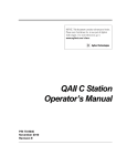
■ Principle of Measurement
The high-intensity GaN green LED radiates light, which will be changed into uniform
parallel light through the special diffusion unit and collimator lens and emitted to the
target in the measuring range. Then the shadow image of the target will appear on the
HL-CCD (high-speed linear CCD) through the telecentric optical system. The output
incident signal of the HL-CCD will be processed by the DE (digital edge-detection)
processor in the controller and CPU. As a result, the dimensions of the target will be
displayed and output.
HL-CCD for
measurement use
Telecentric optical
High-intensity GaN
green LED
system
Special diffusion unit
Target
Collimator lens
Receiver
A/D
conversion
Transmitter
DE
processor
Controller
1-2
CPU
Control input
Control output
BCD output
Analog output
RS-232C interface
Chapter 1 Getting Started
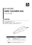
System Applications
The LS-7000 Series has a wide range of applications when used in combination with
commercially available peripheral devices.
Printer
The results of measurement
are printed.
PC
Control values or measuring
values are retrieved over RS232C.
1
Programmable Logic
Controller
Control output and measured
values are retrieved and
programs for measurement
timing control are changed.
RS-232C
RS-232C
Comparator output
BCD output
RS-232C
Timing input
Auto zero input
Reset input
Program number selection
LS-7001
Comparator output
Indicator Light and Buzzer
Alarms are generated according to
the output of discrimination
results.
Analog output
Recorder
The results of
measurement are
recorded.
Timing input
Photoelectric Sensor or
Proximity Sensor
Timing input signals are sent
whenever objects are detected.
1-3
Chapter 1 Getting Started
Package Checks
Check that nothing is missing from the LS-7000 Series package before use.
1
LS-7001
Controller
Four Panel Mounting
Brackets
LS-7000 Series
User’s Manual
96M1
613
`
LS-7010
Measuring Head
Allen-head bolt
(Five, M3 x 45 with a washer)
Allen-head bolt
(Four, M4 x 20)
LS-7030
Measuring Head
Allen-head bolt
(Six, M5 x 45 with a washer)
Allen-head bolt
(Four, M4 x 20)
1-4
Chapter 1 Getting Started
LS-7070
Measuring Head
Allen-head bolt
(Six, M4 x 50 with a washer)
1
Allen-head bolt
(Four, M5 x 20)
LS-C✱✱A
Extension Cable (Cable between the controller and measuring head)
LS-C3A: 3-m cable
✱✱... LS-C10A: 10-m cable
✱✱... LS-C30A: 30-m cable
Up to two cables are connectable, provided that the
total length of the cables does not exceed 40 m.
1-5
Chapter 1 Getting Started
LS-S11
Stand Unit
Base Unit
1
Screws (Four, M4 x 8)
❈ Keyence ships each package with utmost care and attention. If there should be any
improper or damaged product, contact your Keyence representative.
1-6
Chapter 1 Getting Started
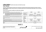
Functions and Nomenclature
The following section provides information on the functions and nomenclature of the
controller and measuring head.
1
Controller
Control Panel
(Page 1-8, Control Panel)
Controller (Rear Side)
Connector I/O
Used for signal I/O
(Page 6-2, Section 6 I/O Pin)
Modular Connector
Used to connect the console connector
or RS-232C cable connector.
(Page 7-4, 7-5, Section 7 RS-232C)
Terminal Block
Used for signal I/O
(Page 6-2, Section 6 I/O Terminals)
Controller (Bottom)
Extension Cable
Connect the cable between the controller and
the measuring head.
Power Input Pins (24 VDC)
Provide 24 VDC power supply.
DC IN
Connect the LS-S11 AC Power Supply
Cable.
1-7
Chapter 1 Getting Started
■ Control Panel
1
OUT 1
OUT 2
HI
(1)
GO
(19)
(20)
LO
TIM
(3)
AREA
1
2
HI
(4)
GO
(5)
(6)
PROG
(21)
POSITION
(2)
(17)
FOCUS
LO
ESC
HOLD
(16)
ZERO
(15)
PRINT
(7)
FUNC
ENT
PROG No.
AREA
DISP
LS-7000
(8) (10) (9) (11) (12)
(1) Main display:
(18)
(13) (14)
The measured value is displayed. Refer to Selection
of Measured Value Display on page 3-2.
(2) Sub display:
Used to display tolerance or measured values while
the LS-7000 Series is in measuring operation. The set
value is displayed while in value setting. Refer to
Selection of Measured Value Display on page 3-2.
(3) Area monitor display:
The number of the selected area is displayed. Refer
to Area Monitor on page 3-4.
(4) Position display:
The position of the target in the selected area is
displayed. Refer to Area Monitor on page 3-4.
(5) Focus display:
The focus status of the selected area is displayed.
Refer to Area Monitor on page 3-4.
Press this key to set program details. Refer to
(6) PROG (Setting) key:
Program Changes on page 3-8.
Press this key to set the setting item. Refer to Section
(7) FUNC (Function) key:
4 Function Settings.
/
key:
Press the Up or Down key to select the set item.
(8)
(9) ESC key:
Press this key to finish the present setting.
(10) ENT key:
Press this key to enter the set item or print the measured value from the printers.
(11) Program number display:
The selected program number is displayed.
(12) Program selection key:
Press this key to select the program number when
measuring. (Page 3-8, Program Change)
(13) Area monitor selection key: Press this key to select the area number when
measuring. (Page 3-4, Area Monitor)
1-8
Chapter 1 Getting Started
(14) Display selection key:
(15)
ZERO
key:
(16)
HOLD
key:
(17)
HI
,
GO
, and
LO
keys:
and
keys:
(18)
(19) Output selection display:
(20) Comparator result display:
(21) Timing display:
Press this key to select the main display or sub
display when measuring. (Page 3-2, Switching
Display Screen)
Press this key to select the auto zero function. (Page
3-6, Automatic Zero Function)
Press this key to select the hold function. (Page 3-5,
Hold Function)
Press these keys to make tolerance settings. (Page 450, Limit Setting)
Press these keys to select the set value or item.
Indicates whether the measured value on the main
display is OUT1 or OUT2.
Displays the comparator result of the main display.
Lit when timing input into the main display turns ON.
1
Measuring Head
LS-7010
Multi-purpose
Mounting Holes
A fixture for targets can
be attached.
Cover Glass
Receiver (R Head)
Receives light from
the transmitter.
Transmitter (T Head)
Emits light for
measurement.
TR Base
Used to mount the
transmitter and receiver.
TR Cables
Used to connect the transmitter
Extension Cable
Connected to the controller.
Mounting Holes
Used to mount the
measuring head.
1-9
Chapter 1 Getting Started
LS-7030
Multi-purpose
Mounting Holes
A fixture for targets can
be attached.
1
Cover Glass
Transmitter (T Head)
Emits light for
measurement.
TR Base
Used to mount the
transmitter and receiver.
Receiver (R Head)
Receives light from
the transmitter.
TR Cables
Used to connect the
transmitter and receiver.
Mounting Holes
Used to mount the measuring head.
Extension Cable
Connected to the controller.
LS-7070
Multi-purpose
Mounting Holes
A fixture for targets can
be attached.
Cover Glass
Receiver (R Head)
Receives light from
the transmitter.
Transmitter (T Head)
Emits light for
measurement.
TR Base
Used to mount the
transmitter and receiver.
TR Cables
Used to connect the
transmitter and receiver.
Mounting Holes
Used to mount the measuring head.
Extension Cable
Connected to the controller.
1-10
Chapter 1 Getting Started
Mounting and Connection
Mount the measuring head and the controller, and connect them with the cables.
1
■ Mounting the Measuring Head
The measuring head can be mounted with or without the TR base employed, according
to the type of targets and operating environment.
The following section provides information on how to mount the measuring head with or
without the TR base employed, along with mounting conditions required.
■ Mounting the Controller
Mount the controller to panels, such as control or operation panels, or to the LS-S11 AC
Power Supply Stand. The LS-S11 Power Supply Stand is sold separately.
■ Connection
After the measuring head and the controller are mounted, connect them with the cables.
Mounting the Measuring Head
■ Mounting Restrictions
The transmitter and receiver must abide by the following restrictions when the measuring head is mounted.
Vertical Position Mismatching
Angle Mismatching
Receiver
±1 mm max.
Transmitter
Receiver
±0.25° max
Transmitter
Receiver
±1 mm max. Transmitter
Receiver
±0.25° max
Transmitter
The values are the same
for LS-7010, LS-7030, and
LS-7070.
Receiver
Receiver
±0.25° max
±0.25° max
Transmitter
Transmitter
1-11
Chapter 1 Getting Started
■ With TR Base
The transmitter and receiver are mounted to the TR base at the time of shipment. This
section provides how to install the transmitter and receiver (LS-7030 in this case) that
are mounted on the TR base.LS-7010 and LS-7070 can also be installed in the same
way.
1
Use the four, M4x20 Allen-head bolts, which
are provided with the package, to mount the
TR base. To mount the TR base with the
bolts on the surface of the TR base, use the
mounting holes on the surface.
To mount the TR base with the bolts on the
back of the TR base, use the 10-mm-deep
M4 (10-mm-deep M5 for LS-7070) mounting
holes on the back.
■ Without TR Base
Take the following steps to use the transmitter and receiver (LS-7030 in this case) after
dismounting them from the TR base. LS-7010 and LS-7070 can also be used in the
same way.
1 Loosen the bolts on the back of the
TR base and remove the measuring
head.
2 Mount the measuring head.
Use the side mounting holes on the
transmitter and receiver as shown in the
illustration. Mount them with the Allenhead bolts provided with the package.
1-12
Chapter 1 Getting Started
Use the 5-mm-deep M4 bottom mounting
holes of the transmitter and receiver as
shown in the illustration.
1
Mounting the Controller
■ Mounting Restrictions
Be aware of the following items when mounting the controller.
CAUTION
Note:
• Do not install the controller upside down.
• Do not block the ventilation louver. Otherwise, the interior heat
may cause the controller to malfunction.
• For the maintenance, operability, and ventilation of the LS-7000
Series, separate the controller as far as possible from peripheral structures or parts.
• The mounting angle must abide by the following restrictions.
30˚
Side
Display
panel
• Check that the controller will not be exposed to the heat radiation of peripheral devices.
• Separate the controller as much as possible from devices with
arc generation, such as electromagnetic switches or non-fuse
breakers.
1-13
Chapter 1 Getting Started
■ Mounting to Panel
The controller can be mounted to control panels with the mounting brackets provided
with the package. Arrange the following panel mounting dimensions.
1
207
169
124
+1
0
+1
0
200
Unit: mm
1 Mount the controller from the front
side of the panel.
2 Attach resin caps to the mounting
brackets.
3 Insert the mounting brackets to the
four mounting holes on the side of
the controller respectively.
Mounting holes
Mounting holes
1-14
Chapter 1 Getting Started
4 Secure the mounting brackets with a
Phillips screwdriver.
1
CAUTION
• Tighten the mounting screws to a maximum torque of 0.4 Nm.
Do not tighten up the mounting screws excessively, otherwise
the panel or controller casing may be deformed.
• Do not remove the gasket, otherwise the controller will not
satisfy IP64 conditions.
■ Mounting to AC Power Supply Stand
The following section provides information on how to mount the controller to the AC
power supply stand (sold separately). The AC power supply stand consists of a stand
unit and base unit. Mount the controller to the stand unit first. Connect the power supply
cable and extension cable (i.e., the cable between the controller and measuring head).
Then mount them to the base unit.
1 Remove the gasket around the
controller.
Gasket
2
Mount the controller to the stand.
Use the two screws provided with the
package and secure the controller on the
side.
The stand must be located
on the groove from which
the gasket was removed.
Secure these
potions with screws.
1-15
Chapter 1 Getting Started
3 Connect the cable between the controller and measuring head.
If only a single measuring head is used,
connect the cable to the HEAD1 connector.
1
Cable between
controller and
measuring head
4 Connect the power supply cable of
the AC power supply stand to the
controller.
5 Mount the stand unit to the base unit.
Mount the stand unit with the two screws
provided with the package.
(2) Lean the stand unit in the
direction indicated by the
arrow. Pay utmost attention so
that the connected cable will
not be caught by the stand unit.
(1) Lean the stand unit in the
front direction and insert
the tab.
(3) Secure these portions
with screws.
1-16
Chapter 1 Getting Started
Tips
The back of the AC power supply
stand has legs. Erect the legs and
use the AC power supply stand if
required.
1
Connection
Connect the measuring head, controller, and power supply with the cables.
CAUTION
Do not supply power to the controller while connecting the
cables. If the AC power supply stand is used, turn off the AC
power supply stand while connecting the cables. The measuring head, controller, or peripheral devices may be damaged if
power is supplied while connecting the cables.
Make the following three connections.
• Transmitter and Receiver:
Connect the cables from the transmitter and receiver
respectively.
• Measuring head and controller: Connect the cable between the controller and measuring head.
• Power supply cable:
Supply 24 VDC to the controller directly or through the
AC power supply stand.
LS-7001
KZ-U3 24-VDC Power Supply
(Optional)
Measuring head
(LS-7010/LS-7030/LS-7070)
Measuring head
(LS-7010/LS-7030/LS-7070)
Power supply cable to the AC
power supply stand
Cable between transmitter and receiver
(OP-42182/OP-42183) (Optional)
Up to two cables are connectable,
provided that the total length of
Cable between controller
Cable between controller
the cables does not exceed 6 m.
and measuring head
and measuring head
(LS-C3A/LS-C10A/LS-C30A)
(LS-C3A/LS-C10A/LS-C30A)
Up to two cables are connectable, Up to two cables are connectable,
provided that the total length of
provided that the total length of
the cables does not exceed 40 m. the cables does not exceed 40 m.
1-17
Chapter 1 Getting Started
■ Transmitter and Receiver
Connect the cables of the transmitter
and receiver respectively.
Connect both connectors so that the
notched part of each connector will coincide
with each other in position.
1
Transmitter side
Receiver side
■ Measuring Head and Controller
Connect the cables of the controller and
the measuring head.
Connect both connectors so that the
notched part of each connector will coincide
with each other in position.
Measuring
head side
Controller side
■ Power Supply Cable
Supply 24 VDC to the controller through I/O terminals 1 and 2 on the rear panel of
the controller. Secure the wires to the terminals with a Phillips screwdriver.
24 VDC
● Using AC Power Supply Stand (Sold
Separately):
Connect the output cable of the AC
power supply stand to the DC IN connector of the controller. Then connect
the AC cord provided with the AC power
supply stand to the electric outlet.
Turning AC Power
1-18
Chapter 1 Getting Started
Supply Stand On and Off
This section provides information on how to turn the AC power supply stand on and off.
1
■ Turning Power On
1 Turn on the POWER switch on the
rear panel of the AC power supply
stand.
■ Turning Power Off
1 Turn off the POWER switch on the
rear panel of the AC power supply
stand.
Measurement and
1-19
Chapter 1 Getting Started
Setting Overview
The LS-7000 Series is in measurement operation according to a variety of settings. The
following section provides information on each mode in detail and how to switch between
modes.
1
Power
On
Tolerance Setting
RUN Mode
OUT 1
OUT 1
OUT 2
HI
GO
TIM
LO
AREA
1
2
POSITION
TIM
HI
GO
HI
FOCUS
HI
GO
LO
OUT 2
HI
GO
LO
LO
GO
Measures according to the set
program.
LO
(See Section 3 Operation Control on
page 3-1)
The above keys
can be pressed to
make tolerance
settings whether or
not the LS-7000
Series is in
measurement
operation.
(See Section 4 Tolerance(LIMIT)
Settings on page 4-50)
Press the PROG key
while pressing the
FUNC key.
PROG
Environment Settings
PROG
PROG
Make basic settings for the
operation of the LS-7000
Series.
(See Section 5 Environment
Settings on page 5-1)
Program Settings
Settings for measurement are registered as programs. The following settings
are possible.
• Area Setting
Set the measuring part.
• Compensation Setting
Set the compensation detail of errors in measurement.
• Output Setting
Set the processing and output details of the measuring value.
• Option Setting
Set the display unit and other items.
See Section 4 Function Settings on page 4-1.
The LS-7000 Series will be reset to the initial status by turning
the LS-7000 Series ON with the ZERO key pressed. (Page 1-21)
1-20
Chapter 1 Getting Started
Resetting to Initial Status
The following section provides information on how to reset all the programs and environment settings to factory-set values.
1
Refer to 5-2 Resetting All Programs on page 5-5 if the resetting of only the
programs to factory-set values is required.
Tips
1 Turn on the LS-7000 Series with the
ZERO
key pressed.
HOLD
ZERO
AREA
This display will appear when the LS7000 Series is turned ON.
DISP
HIGH-ACCURACY CCD MICROMETER
OUT 1
OUT 2
HI
GO
LO
TIM
AREA
1
2
POSITION
HI
GO
FOCUS
PROG
2 Press the
or
LO
ESC
key and select
Yes.
PROG
3 Press the
ENT key after the initialization of the LS-7001 is confirmed.
ESC
PRINT
FUNC
ENT
1-21
Chapter 1 Getting Started
MEMO
1
1-22
Chapter 2
Easy Setting Guide
The LS-7000 Series is used for a variety of measurement
applications if the LS-7000 Series is set properly. This section
provides information on targets and settings for typical
applications respectively.
Measurement of Outer Diameter and Width
(with Single Measuring Head) ............................................. 2-2
Measurement of Outer Diameter and Width
(with Two Measuring Heads) ............................................... 2-3
Measurement of Outer Diameter and Width
(with Two Measuring Heads for Larger Objects) ................. 2-4
Measurement of Inner Diameter and Clearance ................. 2-5
Measurement of Outer Diameter and Eccentricity .............. 2-6
Measurement of Movement and Positioning ....................... 2-7
Measurement of Pitch ......................................................... 2-8
2-1
Chapter 2 Easy Setting Guide
Measurement of Outer Diameter and Width (with Single Measuring Head)
In the following example, a single measuring head is used to measure the outer diameter
of an object in one direction. The result of measurement is displayed as OUT1.
2
D
Measures the outer diameter in one direction.
■ Set Values
Set item
Area setting
Set value
AREA 1
AREA
Calibration
Head 1 DIA
Make settings if required.
OUT 1
Operation
Output
setting
Averaging
Offset
OUT 2
A2: OFF
Select the value according to the line speed.
No settings are required.
Set the upper and lower limit values.
■ Reference
Area Settings (Page 4-7)
Calibration Settings (Page 4-20)
Output Settings (Page 4-28)
Tolerance Settings (Page 4-50)
2-2
No settings are required.
A1: 1.0
Measuring mode Normal
Tolerance setting
AREA 2
No settings are required.
Chapter 2 Easy Setting Guide
Measurement of Outer Diameter and Width (with Two Measuring Heads)
In the following example, two measuring heads are used to measure the average outer
diameter of an object in two directions. The measurement of the object in two directions
ensures high accuracy. The result of measurement is displayed as OUT1.
2
Y
X
D=
X+Y
2
Measures the outer diameter in two directions.
■ Set Values
Set item
Area setting
Set value
AREA
Calibration
Head 2 DIA
Head 1 DIA
Make settings if required.
OUT 1
Operation
Output
setting
AREA 2
AREA 1
Averaging
A2: 0.5
Select the value according to the line speed.
Measuring mode Normal
Offset
Tolerance setting
OUT 2
A1: 0.5
No settings are required.
No settings are required.
Set the upper and lower limit values.
■ Reference
Area Settings (Page 4-7)
Calibration Settings (Page 4-20)
Output Settings (Page 4-28)
Tolerance Settings (Page 4-50)
2-3
Chapter 2 Easy Setting Guide
Measurement of Outer Diameter and Width (with Two Measuring Heads for Larger Objects)
A sheet cannot be located in the measuring area of a single measuring head if the width or
diameter of the sheet is excessively large. In that case, the sheet can be measured with
two measuring heads as shown below with the automatic zero function and the master
workpiece used. The result of output is displayed as OUT1.
2
L
L=
(X+Y)
■ Set Values
Set item
Area setting
Set value
AREA 1
AREA
Calibration
Head 1 B-EDGE
Make settings if required.
OUT 1
Operation
Output
setting
Averaging
Offset
OUT 2
A1: –1.0
A2: –1.0
Select the value according to the line speed.
Measuring mode Normal
Tolerance setting
AREA 2
Head 2 B-EDGE
No settings are required.
Input the size of master workpiece.
Set the upper and lower limit values.
■ Reference
Automatic Zero Function: Measure the master workpiece and make automatic zero
settings. (Page 3-6)
Area Settings (Page 4-7)
Calibration Settings (Page 4-20)
Output Settings (Page 4-28)
Tolerance Settings (Page 4-50)
2-4
Chapter 2 Easy Setting Guide
Measurement of Inner Diameter and Clearance
In the following example, the inner diameter of the workpiece is measured while the
workpiece moves. The maximum value measured is taken as the inner diameter of the
workpiece. The result of output is displayed as OUT1.
2
■ Set Values
Set value
Set item
AREA 1
Area setting
AREA
Calibration
Head 1 SEG
(001-E, 002-E)
Operation
Averaging
Offset
OUT 2
A1: 1.0
A2: OFF
Select the value according to the line speed.
Measuring mode Peak hold
Tolerance setting
No settings are required.
Make settings if required.
OUT 1
Output
setting
AREA 2
No settings are required.
No settings are required.
Set the upper and lower limit values.
■ Reference
Area Settings (Page 4-7)
Calibration Settings (Page 4-20)
Output Settings (Page 4-28)
Tolerance Settings (Page 4-50)
2-5
Chapter 2 Easy Setting Guide
Measurement of Outer Diameter and Eccentricity
In the following example, the outer diameter and eccentricity of the roller is measured while
the roller moves. The outer diameter is displayed as OUT1, and the eccentricity is displayed as OUT2.
2
Eccentricity
Outer diameter
■ Set Values
Set item
Area setting
Set value
AREA 2
AREA 1
AREA
Calibration
Head 1 DIA
Head 1 T-EDGE
Make settings if required.
OUT 1
Output
setting
Operation
Averaging
A1: 1.0
A2: OFF
A2: 1.0
1
Select the value according to the rpm.
Measuring mode Average hold
Offset
Tolerance setting
No settings are required
Set the upper and lower limit values.
■ Reference
Area Settings (Page 4-7)
Calibration Settings (Page 4-20)
Output Settings (Page 4-28)
Tolerance Settings (Page 4-50)
2-6
OUT 2
A1: OFF
Peak-to-peak hold
No settings are required
Chapter 2 Easy Setting Guide
Measurement of Movement and Positioning
In the following example, the movement or position of the workpiece is measured. The
result of output is displayed as OUT1.
2
■ Set Values
Set value
Set item
AREA 1
Area setting
AREA
Calibration
(000-E, 002-E)
Operation
Averaging
Offset
OUT 2
A1: 1.0
A2: OFF
Select the value according to the line speed
Measuring mode Normal
Tolerance setting
No settings are required
Make settings if required.
OUT 1
Output
setting
AREA 2
Head 1 SEG.
No settings are required
No settings are required
Set the upper and lower limit values.
■ Reference
Area Settings (Page 4-7)
Calibration Settings (Page 4-20)
Output Settings (Page 4-28)
Tolerance Settings (Page 4-50)
2-7
Chapter 2 Easy Setting Guide
Measurement of Pitch
The single pitch of connectors pins or IC pins is measured by the LS-7000 Series. Furthermore, multiple pitch of pins is measured with the program function or RS-232C interface
used.
2
The center pitches of the two portions
are measured at a time.
■ Set Values
Set value
Set item
AREA 1
Area setting
AREA
Calibration
AREA 2
Head 1 SEG
Head 1 SEG
(002-P, 004-P)
(004-P, 006-P)
Make settings if required.
OUT 1
Operation
Output
setting
Averaging
A1: OFF
A2: OFF
A2: 1.0
Select the value according to the line speed Select the value according to the line speed
Measuring mode Sample hold 1/2
Offset
Tolerance setting
No settings are required
Set the upper and lower limit values.
■ Reference
RS-232C (Page 7-1)
Area Settings (Page 4-7)
Calibration Settings (Page 4-20)
Output Settings (Page 4-28)
Tolerance Settings (Page 4-50)
2-8
OUT 2
A1: 1.0
Sample hold 1/2
No settings are required
Chapter 3
Operation Control
This section provides information on setting control items on
the control panel while the LS-7000 Series is in measurement
operation.
Selection of Measured Value Display .........................
Area Monitor ................................................................
Hold Function ..............................................................
Automatic Zero Function .............................................
Panel Lock Function ....................................................
Program Changes .......................................................
3-2
3-4
3-5
3-6
3-7
3-8
3-1
Chapter 3 Operation Control
Selection of Measured Value Display
Displayed values on the main and sub displays can be switched. The main display can
display the measured results of OUT1 (or OUT2) and the sub display can display tolerance
comparator set values or measured values simultaneously. Four display types can be
selected in two tolerance modes (i.e., the reference value mode and threshold mode).
Refer to Option settings on page 4-54 for the selection of the reference value mode or
threshold mode.
Press the DISP (display) key and select
the value or item.
The following displayed values can be
selected.
3
HOLD
ZERO
AREA
DISP
■ Tolerance Mode with Reference Value
OUT1 is lit.
OUT1 measured value is displayed.
OUT 1
OUT 2
HI
GO
LO
TIM
AREA
1
2
OUT1 upper limit is displayed.
POSITION
HI
OUT1 reference value is displayed.
OUT1 lower limit is displayed.
GO
FOCUS
LO
DISP
DISP
OUT2 is lit.
OUT2 measured value is displayed.
OUT 1
OUT 2
HI
GO
LO
TIM
AREA
1
2
OUT2 upper limit is displayed.
POSITION
HI
OUT2 reference value is displayed.
GO
FOCUS
LO
OUT2 lower limit is displayed.
DISP
DISP
OUT1 is lit.
OUT1 measured value is displayed.
OUT 1
OUT 2
HI
GO
LO
TIM
AREA
1
2
POSITION
HI
OUT2 measured value is displayed.
GO
FOCUS
LO
DISP
DISP
OUT 1
OUT 2
HI
GO
LO
OUT2 is lit.
OUT2 measured value is displayed.
TIM
AREA
1
2
POSITION
HI
GO
FOCUS
3-2
LO
OUT1 measured value is displayed.
Chapter 3 Operation Control
■ Tolerance Mode with Threshold
Out 1 is lit.
Out 1 measured value is displayed.
OUT 1
OUT 2
HI
GO
LO
TIM
AREA
1
2
POSITION
Out 1 HI value is displayed.
HI
GO
FOCUS
Out 1 LO value is displayed.
LO
DISP
DISP
3
Out 2 is lit.
Out 2 measured value is displayed.
OUT 1
OUT 2
HI
GO
LO
TIM
AREA
1
2
POSITION
Out 2 HI value is displayed.
HI
GO
FOCUS
Out 2 LO value is displayed.
LO
DISP
DISP
Out 1 is lit.
Out 1 measured value is displayed.
OUT 1
OUT 2
HI
GO
LO
TIM
AREA
1
2
POSITION
HI
Out 2 measured value is displayed.
GO
FOCUS
LO
DISP
DISP
OUT 1
OUT 2
HI
GO
LO
Out 2 is lit.
Out 2 measured value is displayed.
TIM
AREA
1
2
POSITION
HI
GO
FOCUS
Tips
Out 1 measured value is displayed.
LO
The displayed settings are saved in the program settings.
3-3
Chapter 3 Operation Control
Area Monitor
The area monitor display can be used to confirm the insertion positions of the targets in
AREA1 or AREA2 to be selected.
Press the AREA key on the control panel
and select the area.
The following items will be displayed when
the area is selected.
3
HOLD
ZERO
AREA
DISP
The selected area number is lit.
AREA
1
2
POSITION
POSITION Monitor
The POSITION monitor is lit
according to the position and size of
the target in the CCD scanning
range.
FOCUS
AREA
AREA
AREA
1
2
FOCUS monitor
The FOCUS monitor is lit according
to the distance between the
receiver and target.
POSITION
FOCUS
Tips
3-4
The displayed settings are saved in the program settings.
Chapter 3 Operation Control
Hold Function
Measured values can be held and displayed. Furthermore, measuring mode combinations
allow the measurement of a variety of values, such as maximum and minimum values. The
types of measured values held vary with the measuring mode.
Refer to Measuring Mode on page 4-33 for details.
Measured values are held and displayed through the following functional components.
• Control panel
• External I/O terminals
• RS-232C interface
3
■ Control Panel
If either the OUT1 or OUT2 measured value is displayed, the displayed value will be
held. If both OUT1 and OUT2 measured values are displayed, both values will be held.
Press the HOLD key on the control panel.
When the measured value is held, the TIM
indicator on the right-hand side of the main
display will be lit. To cancel the hold status,
press the HOLD key again.
HOLD
ZERO
AREA
Tips
DISP
By pressing the ESC key, the
measured value kept on hold will
be reset.
■ External I/O Terminals
Measured values will be held by short-circuiting the timing input terminal and COM
terminal together on the rear panel of the controller.
Refer to Section 6 I/O Terminals on page 6-1 for the external input terminals to be used.
■ RS-232C Interface
Commands sent by external devices through the RS-232C interface make it possible to
put measured values on hold.
Refer to Section 7 RS-232C on page 7-1 for the commands in detail.
3-5
Chapter 3 Operation Control
Automatic Zero Function
The automatic zero function sets measured values to zero (0.00000) instantly. This function
is convenient for zero-point calibration for a variety of targets. Furthermore, master calibration is possible by using this function in combination with the offset function.
Note:
Tips
3
This function will not be available while the controller is awaiting the result of
measurement, during which the monitor will display “– – –. – – – –.”)
The automatic zero value will not be lost after the LS-7000 Series is turned
off. The automatic zero value for each program will be stored.
Automatic zero settings are made through the following functional components.
• Control panel
• External terminal
• RS-232C interface
■ Control Panel
When only the OUT1 or OUT2 measured value is displayed, auto zero setting is made
for the displayed value. If both OUT1 and OUT2 values are displayed, auto zero setting
is made for both values.
Press the ZERO key on the control panel.
Press the ZERO key again to cancel the auto
zero setting.
HOLD
ZERO
AREA
DISP
■ External I/O Terminal
Auto zero setting is made by short-circuiting the ZERO and COM terminals on the rear
panel of the controller. Refer to Section 6 I/O Terminals on page 6-1 for details.
Note:
Automatic zero cannot be canceled through the external I/O terminals.
■ RS-232C Interface
Commands sent by external devices through the RS-232C interface make it possible to
set or cancel the automatic zero function. Refer to Automatic Zero ON/OFF on page 710 for details.
Tips
3-6
Master Calibration with Offset Function (Automatic Offset Function)
Set the size of a master workpiece to an offset value and make an automatic
zero setting while measuring the master workpiece. Then the size of the
master workpiece will be displayed as an offset value. Refer to Measurement
of Outer Diameter and Width (with Two Measuring Heads) on page 2-4 for an
application example. Refer to Offset on page 4-43 for the offset function in
detail.
Chapter 3 Operation Control
Panel Lock Function
The panel lock function is used to lock the control panel so that no key input will be enabled. As a result, there will be no risk of making setting changes with careless key input.
Panel Lock Types
The following types of panel locks are possible with the PAN-LOC settings as environment
settings. Refer to Panel Lock on page 5-13 for details.
• Set the panel lock type to ALL: All keys will be locked.
• Set the panel lock type to PART: All keys excluding the DISP and AREA keys for the
display change function and HI , GO , and LO keys
for the tolerance setting function and HOLD key will be
locked. Select this type if you make tolerance changes
frequently without changing any other setting.
3
Panel Lock Display
The decimal in the PROG No. display will flash
while the panel is locked.
C
NT
NT
Tips
The panel lock status will not be
lost after the LS-7000 Series is
turned off or program number
changes are made.
PROG No.
Panel lock settings are made through the following functional components.
• Control panel
• RS-232C interface
■ Control Panel
Press the
and
keys on the
control panel together for 2 seconds.
To cancel the panel lock status, repeat the
above.
PROG
ESC
PRINT
FUNC
ENT
PRO
■ RS-232C Interface
Commands sent by external devices through the RS-232C interface make it possible to
set or cancel the panel lock function. Refer to Panel Lock ON/OFF on page 7-11.
3-7
Chapter 3 Operation Control
Program Changes
The following section provides information on how to call 16 programs saved in the LS7000 Series.
Names and Number of Programs
The selected program is displayed on the
display monitor next to the [PROGRAM No.]
key.
It is possible to register 16 alphanumeric
characters (i.e., 0 through 9 and A through F)
for program numbers.
Programs are selected through the following
functional components.
• Control panel
• External I/O terminals
• RS-232C interface
3
Note:
C
NT
NT
PROG No.
The operation method varies with the P-SELECT setting as an environmental
setting. Refer to Program on page 5-5 for environment settings in detail.
P-SELECT setting
Operation method
PANEL
Control panel/RS-232C interface
TERMINAL
I/O terminals (P1 through P4)
■ Control Panel
Press the [PROGRAM No.] key ( or
key) on the control panel.
The program numbers will be displayed in
sequence by pressing the key repeatedly.
ESC
PRINT
ENT
PROG No.
■ External I/O Terminals
External I/O terminals P1 through P4 on the rear panel of the controller can be used for
program selection. Refer to Section 6 I/O Terminals on page 6-1 for external I/O terminals to be used and program numbers in detail.
■ RS-232C Interface
Commands sent by external devices through the RS-232C interface make it possible to
select programs. Refer to PROGRAM No. on page 7-11 for the RS-232C interface in
detail.
3-8
Chapter 4
Function Settings
The LS-7000 Series is available to the measurement of a
variety of items by making setting changes. These settings
can be registered as programs that can be used whenever
required. This section provides information on the overview of
program settings and setting methods.
Flow of Program Settings ............................................ 4-2
Default Values and Possible Setting Ranges .............. 4-4
Copying Program Setting Details and Initialization ..... 4-6
Area Settings ............................................................... 4-7
Calibration Settings ................................................... 4-20
Output Settings ......................................................... 4-28
Tolerance (LIMIT) Settings ........................................ 4-50
Option Settings .......................................................... 4-54
4-1
Chapter 4 Function Settings
Flow of Program Settings
The following section provides information on the types and flows of program settings
available to the LS-7000 Series along with the relationship between the program settings
and external I/O.
Area Settings (See page 4-7)
Calibration Settings (See page 4-20)
Calibration Settings (Optional)
Measuring head Selection
Measuring head 1 (HEAD1)
Measuring head 2 (HEAD2)
4
■
Logic calibration
Two-point calibration
One-point calibration
Area Selection
■
DIA
T-EDGE
B-EDGE
SEG
Select the number of
edges and mode (E/P)
Optional Settings
Focus monitor
Area check
■ Difference check
■
■
Averaging
number
Difference
value
Function output
■ Edge detection threshold
■
Area 1
Area 2
Environment Settings (See page 5-1)
Program
RS-232C
■ Head
4-2
■
■
■
■
Buzzer
Panel lock
Calibration mode selection
Calibration Value Initialization
Chapter 4 Function Settings
External I/O
Output Settings (See page 4-28)
Optional Settings
Area calculation
Averaging number
■ Offset
(in combination with the automatic zero function)
■
■
4
ZERO
TIMING
Measuring Mode Settings
RESET
Output Settings
■
Analog output settings
Scaling (Reference value/Threshold)
Analog update mode
Output waiting voltage
Analog output
■
Comparator output settings
Comparator output
Strobe output
Output logic
Off-delay time
OUT1
OUT2
Function output
Option Settings (See page 4-54)
■
Tolerance mode
■ I/O mode
mm
μm
Reference value
SUB
inch
Threshold
BCD
mil
■ Minimum display unit
■
Unit
BCD output
4-3
Chapter 4 Function Settings
Default Values and Possible Setting Ranges
The following programs settings are made by default.
Items in parentheses indicate what is displayed on the monitor.
■ Area Settings (AREA) (Page 4-7)
Item
Default
Measuring head selection (HEAD No.)
1
Possible setting range
1, 2
Diameter (DIA)
Top edge (T-EDGE)
Area (AREA)
DIA
Bottom edge (B-EDGE)
Segment (SEG)
Specified SEG edge number: -127 to +127
4
SEG mode: Edge (E) or Pitch (P)
Focus monitor (FOCUS)
Area check (A-TEST)
Difference
Averaging number (AVE)
check (DIFF) Difference value
5
OFF
1
1000
0 to 9
OFF (No area check), 2 to 127
1, 2, 4, 8, 16
1 to 9999 (in μm, mm, inch, or mil)
Focus monitor (FOCUS),
Function output setting (FUNCTION)
FOCUS
Area check (A-TEST),
Difference check (DIFF)
Edge detection threshold (LEVEL)
50
10 to 99
■ Calibration Settings (CALIB) (Page 4-20)
Item
Calibration mode (CAL-MODE)
Default
Possible setting range
THEORY Logic calibration (THEORY),
2-point calibration (2-TARGET),
or 1-point calibration (1-TARGET)
–99.99995 to +99.99995mm ❈
T1-A/T1-B/T2-A/T2-B
■ Tolerance Settings (LIMIT) (Page 4-50)
Item
Threshold
mode
(TOL)
Reference
+40.00000
HI output range (HI)
+30.00000
LO output range (LO)
0.00000
LL output range (LL)
-10.00000
HOLD-H
OFF
HOLD-L
OFF
STANDARD
+10.00000
UPPER
+1.00000
value mode LOWER
(DEV)
HOLD-H
HOLD-L
4-4
Default
HH output range (HH)
Possible setting range
-99.99995 to +99.99995mm ❈
OFF, -99.99995 to +99.99995mm ❈
-99.99995 to +99.99995mm ❈
-1.00000
OFF
OFF
OFF, -99.99995 to +99.99995mm ❈
Chapter 4 Function Settings
■ Output Settings (OUTPUT) (Page 4-28)
Item
Area calculation (CALC)
Averaging number (AVERAGE)
Default
OUT1: A1 1.0 A2 OFF
OUT2: A1 OFF A2 1.0
512
Measuring mode (MEA-MODE)
Normal
Offset (OFFSET)
Scaling at +10 V
(A-OUT +10)
Threshold
(TOL)
Scaling at –10 V
(A-OUT –10)
Reference
Scaling (A-UNIT)
value (DEV)
Analog output setting: Analog update mode (A-SET)
0.00000
+30.00000
Possible setting range
OFF, 1.0, 0.5, –1.0, –0.5
1, 2, 4, 8, 16, 32, 64, 128, 256, 512, 1024,
2048, 4096
Normal (NORMAL)
Peak hold (P-HOLD)
Bottom hold (B-HOLD)
Peak-to-peak hold (D-HOLD)
Average hold (AV-HOLD)
Automatic peak hold (A-P-HOLD)
Automatic bottom hold (A-B-HOLD)
Automatic peak-to-peak hold (A-D-HOLD)
Sample hold 1 (S-HOLD1)
Sample hold 2 (S-HOLD2)
Self-timing hold (SELF-T)
Self-timing period: 1 to 9999 ms
(By default set to 100 ms)
4
-99.99995 to +99.99995mm ❈
0.00000
1000 μm/V
OFF
Analog output setting: Output
waiting voltage (A-CONT)
+10.5V
Comparator output setting: Strobe
output time (STOBE-T)
0.4ms
1, 2, 5, 10, 20, 50, 100, 200, 500, 1000, 2000,
5000, 10000 μm/V
OFF, ON
+10.5V, Hold, 0V
0.4, 0.8, 1.6, 3.3, 6.6, 13.3, 26.6ms
Comparator output setting: Output
logic (OUT-SET)
N.O.
Normally open (N.O.)
Normally closed (N.C.)
Comparator output setting:
Off-delay time (OFF-DLY)
0ms
0, 0.4, 0.8, 1.6, 3.3, 6.6, 13.3, 26.6ms
■ Option Settings (OPTION) (Page 4-54)
Item
Tolerance mode (LIMITS)
Timing mode (T-MODE)
Unit (D-UNIT)
Minimum display unit (D-RES)
I/O mode (C-OUT)
Default
DEV
ASYNC
mm (UNIT1)
0.00005
SUB
Possible setting range
Reference value (DEV) or threshold (TOL)
Synchronous (SYNC) or asynchronous (ASYNC)
mm (UNIT1), μm (UNIT2), inch (UNIT3), mil (UNIT4)
mm: 0.00001, 0.00002, 0.00005,
0.0001, 0.0002, 0.001,
0.01, 0.1
SUB mode (SUB), BCD mode (BCD)
❈ Displayed values are based on a minimum display unit of 0.00005 millimeters. Refer
to page 4-60 for other types of minimum display units.
4-5
Chapter 4 Function Settings
Copying Program Setting Details and Initialization
The LS-7000 Series can be initialized so that the details of programs will return to ones set
by default. Furthermore, the LS-7000 Series has a function making it possible to copy the
details of any program to different programs.
Copying Program Setting Details
The details of any program can be copied to different programs by using the P-COPY
item as an environment setting. Refer to Copying Programs on page 5-5 for details.
Types of Initialization
The following three types of initialization are available.
• Initialization of a single program
• Initialization of all programs
• Total initialization of all programs and environment settings.
4
■ Initialization of Single Program
The details of a single program can be initialized by using the P-COPY item as an
environment setting. Refer to Copying Programs on page 5-5 for details.
■ Initialization of All Programs
The details of all programs can be initialized by using the P-CLEAR item as an environment setting menu. Refer to Resetting All Programs on page 5-6.
■ Program Initialization
The LS-7000 Series can be initialized so that the details of programs and environment
settings will return to ones set by default. Refer to Resetting to Initial Status for details
on page 1-21.
4-6
Chapter 4 Function Settings
Area Settings
Area settings are used to determine the measurements taken from a variety of objects
placed in the beam. The LS-7000 Series can use up to two measuring heads to set two
measurements (AREA1 and AREA2) for simultaneous measurements.
Area Settings
Area settings include the following items.
• Area:
Select the measuring head number together with
the DIA, T-EDGE, B-EDGE, or SEG mode.
• Focus monitor:
A function to check whether the target is within the
measuring range. Set the best measuring range
(i.e., the distance between the target and transmitter) with this function.
• Area check:
Set the total number of edges to be measured. If
the number of edges detected does not coincide
with the set value, the measured value will be
invalidated.
• Difference check:
If there is a radical change between measured
values, the change will be detected and output.
Set the value for the change to be detected.
• Function output selection:
Set the items to be output from the output terminal
on the rear panel.
• Edge detection threshold change: Set the threshold to be detected when measuring
highly transparent objects.
4
Area Setting Procedure
Make settings while monitoring the sub display.
The following procedure is for area settings for measuring head 1.
1 Press the
PROG
key.
PROG
ESC
PRINT
FUNC
ENT
2 Check that the area to be set will
appear. Press the ENT key.
To set AREA2, press the FUNC key. Then
press the ENT key.
HI
GO
LO
3 The area setting screen will appear.
Press the FUNC key to select another set
area item.
HI
GO
LO
4-7
Chapter 4 Function Settings
Flow of Area Setting Display
OUT 1
OUT 2
HI
GO
LO
TIM
AREA
1
2
POSITION
HI
GO
FOCUS
PROG
This part changes.
LO
ESC
HOLD
PRINT
FUNC
ZERO
ENT
PROG No.
AREA
DISP
LS-7000
Area Setting
4
HI
GO
PRINT
LO
ENT
HI
FUNC
Area Setting
(See page 4-9)
GO
LO
HI
GO
ESC
FUNC
LO
HI
Focus Monitor
(See page 4-14)
GO
LO
FUNC
HI
Area Check
(See page 4-15)
GO
LO
FUNC
HI
GO
Difference
Check
(See page 4-16)
LO
FUNC
HI
GO
LO
Function
Output
Selection
(See page 4-17)
FUNC
HI
GO
LO
4-8
Change of
Edge Detection
Threshold
(See page 4-18)
Chapter 4 Function Settings
Area Selection
Area
When a target is located in the measuring area as shown below, the light into the
receiver is partly obstructed, thus creating a shadow.
The contour of the shadow is called “edge.” The area is surrounded by the edge line.
The LS-7000 Series can measure objects with area designation or edge designation.
Area designation is possible in DIA, T-EDGE, or B-EDGE mode. Edge designation is
possible in SEG mode.
EDGE
AREA
Target
EDGE
AREA
AREA
Transmitter
EDGE
EDGE
Receiver
4
■ DIA (Diameter)
When the LS-7000 Series is in DIA measurement operation, it measures the outer
diameters of round bars or transparent
objects. The area between the top of the
first shadow and the bottom of the last
shadow is measured as shown in the
illustrations.
This space is
measured.
Target
Transmitter
Receiver
This space is
measured.
Target
Transmitter
Receiver
4-9
Chapter 4 Function Settings
■ T-EDGE (Top Edge)/B-EDGE (Bottom Edge)
Select either of these settings for the gap
measurement or positioning of rollers.
4
When the LS-7000 Series is in T-EDGE measurement operation, it measures the width of
the bright portion between the top of the measuring head and the first shadow in the
measuring area.
When the LS-7000 Series is in B-EDGE measurement operation, it measures the width of
the bright portion between the bottom of the measuring area and the bottom of the last
object in the beam.
This space is measured in
T-EDGE mode or B-EDGE
mode.
Target
Transmitter
Receiver
This space is measured in
T-EDGE mode.
Target
This space is measured in
B-EDGE mode.
Transmitter
Tips
Receiver
Setting the reference edge within the measuring area enables measurements
in higher repeat accuracy.
■ SEG (Segment)
Select this setting for the measurement of the inner diameters of discs or the measurement of pitches.
The edge where the measurement of the object in the measuring area starts is called
“start edge” and the edge where the measurement terminates is called “end edge.” The
space between these edges specified is measured.
Segment measurement is performed in E mode or P mode. If objects are measured
with the virtual center of the light axis set, use edge 0.
Setting Range
• Edge or pitch numbers can be designated between –127 and 127.
• The duplicated designation of an edge or pitch number will set the measured value to
0.
• If edges or pitches are designated in reverse order, negative measured values will be
obtained.
4-10
Chapter 4 Function Settings
E (Edge) Mode
The LS-7000 Series measures objects
based on the edges in this mode.
4
Set the edge numbers to positive values beginning with the top of the measuring head.
The following example shows positive edge numbers and measuring portions.
Top
1E
2E
Outer diameter 1
Clearance
Outer diameter 2
3E
4E
5E
6E
Outer diameter 1: Space between 2E and 3E
(+2E to +3E)
Outer diameter 2: Space between 4E and 5E
(+4E to +5E)
Clearance:
Space between 3E and 4E
(+3E to +4E)
Bottom
Set the edge numbers to negative values beginning with the bottom of the measuring
head. The following example shows negative edge numbers and measuring portions.
Top
-6E
-5E
Outer diameter 1
Clearance
Outer diameter 2
-4E
-3E
-2E
-1E
Outer diameter 1: Space between –5E and –4E
(–5E to –4E)
Outer diameter 2: Space between –3E and –2E
(–3E to –2E)
Clearance:
Space between –4E and –3E
(–4E to –3E)
Bottom
4-11
Chapter 4 Function Settings
P (Pitch) Mode
The LS-7000 Series measures objects
based on the middle point between the
edges of the objects in this mode.
In this example as shown, five P-mode
edges exist, based on which the LS-7000
measures the center pitch of the target in
the measuring area.
Center pitch: The space between 2P and
4P
4
Top
1E
2E
Target center pitch
1P
2P
3E
4E
5E
Edge 0
Edge 0 refers to a method of measurement, in which the center of the optical
axis is used as an origin. In this case,
set the edge number to 0.
3P
4P
5P
6E
Bottom
Use this method to position the objects or measure the movement or deviation of
objects.
Top
1E
Center of
optical axis
35.5 ± 0.2
Edge 0
2E
Bottom
Tips
Edge position of workpiece
: Space between+1E and 0
(+1E to 0E)
In the edge 0 method, the E and
P modes will not make any difference.
Use edge 0 method if higher repetitive accuracy is required from the measurement of objects.
■ Setting Procedure
1 Select the area to be set and press the
ENT
key.
2 Press the
or
key and select
the measuring method.
LO
HI
GO
Set the following items that appear on the
LO
4-12
Chapter 4 Function Settings
screen.
AREA
1
2
POSITION
FOCUS
PROG
ESC
H
PRINT
FUNC
Z
ENT
PROG No.
AREA
DISP
HI
Measuring head No. 1
HI
DIA (Diameter)
HI
Measuring head No. 2
HI
T-EDGE (Top edge)
HI
B-EDGE (Bottom edge)
GO
SEG (Segment)
LO
4
SEG (Segment) Setting
Input the start edge (pitch) number.
The value must be smaller than the end
edge (pitch number).
HI
The setting part
flashes.
GO
Select the E or P
mode as desired.
LO
Input the end edge
(pitch) number.
The value must be
larger than the start
edge (pitch) number.
Note:
• The duplicated designation of an edge or pitch number will set the measured value to 0.
• If edges or pitches are designated in reverse order, negative measured
values will be obtained.
(1) Input the start edge (pitch) number.
LO
Press this key to set
the value to a positive
or negative one.
HOLD
ZERO
PROG No
Press these keys
to set the value.
(2) Press the
ENT
key.
AREA
DISP
Select the E or P mode
with these keys.
4-13
Chapter 4 Function Settings
The input value is entered and the value in the next line flashes.
(3) Input the end edge (pitch) number.
4 Press the
ENT key.
The input value is entered and the area display appears again.
Focus Monitor
The focus monitor is a function that makes it possible to check whether the target is located within the range where the highest precision measurement of the target is ensured.
The focus monitor range is the distance between the receiver and target in the measuring
area. When the target is within the range specified, the FOCUS indicator will light.
FOCUS display is lit Focus display is OFF
4
The center of the measuring area
Setting Range
The value is set at 10 levels between 0 and 9. Set the value to 0 if the focus monitor
function is not used. Refer to Focus Characteristics on page 8-6 for the set values and
focus range in detail.
The result of focus monitoring can be externally output as function output.
Refer to Selection of Function Output on page 4-17 for details.
Tips
■ Setting Method
1 Select the area to be set and press
the
ENT
key.
HI
2 Press the
FUNC
key.
GO
LO
3 Press the
or
key and set the
value.
AREA
1
2
4 Press the
ENT key after the value is
set.
The input value is entered and the area
display appears again.
POSITION
FOCUS
PROG
ESC
H
PRINT
FUNC
Z
ENT
PROG No.
4-14
AREA
DISP
Chapter 4 Function Settings
Area Check
Set the total number of edges to be measured. If the number of edges detected does not
coincide with the set value, the measured value will be invalidated.
This function makes it possible to prevent the measurement of abnormal values that may
result if dust or oil is stuck on the measuring head.
The monitor will display the following data if the
measured value is invalidated.
OUT
OUT
HI
GO
LO
TIM
AREA
1
2
POSITION
HI
GO
FOCUS
LO
Setting Range
The setting range is between 2 and 127. Set the value to OFF if no area check is made.
Tips
4
The result of area checking can be external output as function output. Refer to
Selection of Function Output on page 4-17 for details.
■ Setting Method
1 Select the area to be set and press
the
ENT
HI
key.
2 Press the
FUNC
key twice.
GO
LO
3 Press the
or
ON/OFF settings.
key and make
AREA
1
2
POSITION
FOCUS
PROG
ESC
H
PRINT
FUNC
Z
ENT
PROG No.
AREA
DISP
ON Setting
(1) Input the number of edges to be measured.
The setting part
flashes.
LO
HOLD
Press these keys
to set the value.
ZERO
PROG No
AREA
DISP
4 Press the
ENT key after the value is set.
The input value is entered and the area display appears again.
4-15
Chapter 4 Function Settings
Difference Check
If there is a radical change between measured values, the change will be detected and
output.
Setting Range
• Difference average: 1 to 16 times
• Difference value: 1 to 9999 μm
Note:
The results of difference checks will be output externally, provided that DIFF
function output settings are made properly in advance. Refer to Function
Output Selection on page 4-19 for details.
The result output of a difference check is a 26.6-ms-long single output signal,
which is not displayed on the control panel.
■ Setting Method
4
1 Select the area to be set and press
the
ENT
HI
key.
2 Press the
FUNC
key three times.
GO
LO
3 Press the
or
key and set the averaging number.
POSITION
AREA
1
2
Averaging times
G
FOCUS
PROG
ESC
H
PRINT
FUNC
The setting
part flashes.
L
ZE
ENT
PROG No.
AREA
DISP
Press these
keys to set
the value.
4 Press the
ENT key.
The input value is entered and the difference value display flashes.
5 Press the
or
key and set the difference value.
2
G
The setting
part flashes.
FOCUS
PROG
L
ESC
H
PRINT
FUNC
ZE
ENT
PROG No.
Press these keys
to set the value.
4-16
AREA
DISP
Difference
value
Chapter 4 Function Settings
6 Press the
ENT key after the value is set.
The input value is entered and the area display appears again.
Function Output Selection
Select either Focus, Area, or Difference to be output from the output terminal block on the
rear panel.
Setting Range
Any one of the following items is selectable for output. Refer to Section 6 I/O Terminals
on page 6-1 for the FUNCTION output terminals in details.
• Focus monitor
• Area check
• Difference check
■ Setting Method
4
1 Select the area to be set and press
the
ENT
HI
key.
2 Press the
FUNC
key four times.
GO
LO
3 Press the
or
key and set the output item.
AREA
1
2
POSITION
Selected item
FOCUS
PROG
ESC
H
PRINT
FUNC
Z
ENT
PROG No.
AREA
DISP
The following items are displayed for
setting.
HI
Focus monitor
HI
Area check
HI
Difference check
4 Press the
ENT key.
The input value is entered and the area
display appears again.
4-17
Chapter 4 Function Settings
Change of Edge Detection Threshold
The following section provides information on how to make threshold changes for the
measurement of highly transparent objects.
Transparent
tape
Optical
reception
Measuring range
Brighter
4
Optical reception
Threshold
(80%)
Brighter
Light blocked
by tape
Threshold
(50%)
Darker
Detection impossible
Darker
Detection
possible
Position
Position
80% threshold
50% threshold
When measuring a highly transparent
target, such as a plastic tape, the
amount of light blocked by the tape is
minimal. Therefore, the tape may not be
detected if the threshold is low.
In that case, increase the threshold level
so that the tape will be detected
Setting Range
The threshold can be set between 10% and 99% in 1% increments.
Note:
• Only a single threshold can be set for each measuring head.
• In the measurement using the window edge such as T-EDGE or B-EDGE,
the measurement may become unstable with a higher threshold. In such a
case, use the reference edge or edge 0.
■ Optical Reception Waveform Output
While making a threshold setting for the target in the measuring area, an oscilloscope
can be used to output the optical reception waveform of the target so that the threshold
can be adjusted while monitoring the waveform.
Approx.
10 ms
Trigger pulse
Optical reception waveform
(OUT1 analog output on terminal 22)
10V
Approx. 6.5 V
Threshold level
(OUT2 analog output on terminal 23)
0V
Approx. 450 ms
4-18
Chapter 4 Function Settings
■ Setting method
1 Select the area to be set and press
the
ENT
HI
key.
2 Press the
GO
FUNC
key five times.
LO
3 Press the
or
key and set the threshold.
AREA
1
2
POSITION
Threshold
G
FOCUS
PROG
The setting part
flashes.
L
ESC
4
H
PRINT
FUNC
ZE
ENT
PROG No.
AREA
DISP
Press these keys
to set the value.
4 Press the
ENT key.
The input value is entered and the area display appears again.
4-19
Chapter 4 Function Settings
Calibration Settings
The measured value of a target may have a subtle error due to the surface condition and
angle of the target. Calibration settings correct for this error. It is possible to make calibration settings for each area independently.
■ Types of Calibration Settings
Select the type of calibration from the following ones in advance. Refer to Calibration
Type Selection on page 4-23.
Logic calibration:
Logic calibration requires two types of master workpieces that are
different to each other in size. Calibration is performed according
to pre-calibration and post-calibration values that are input by the
user. This type of calibration is used for the measurement of the
distance between two workpieces, for example.
Two-point calibration: Two-point calibration requires two types of master workpieces that
are different to each other in size.
One-point calibration: One-point calibration requires a single master workpiece. This
calibration is used for the size measurement of a single type of
workpiece.
4
Logic Calibration/Two-point Calibration
Prepare target 1 (T1) and target 2 (T2) as
two measuring points. The LS-7000 Series
performs calibration on these points based
on the T1-A and T2-A display values, which
are obtained before calibration, and the T2B and T2-B display values, which are
obtained after calibration. In this case, the
non-calibrated display values are converted
into the calibrated display values with the
span value (inclination) and shift value of
the workpiece determined by the LS-7000
Series internally.
One-point Calibration
Prepare target 1 (T1) as a single measuring
point. The LS-7000 Series performs calibration on this point based on the display value
before calibration and that after calibration.
In this case, the non-calibrated display
value is converted into the calibrated display
value with the span (inclination) and shift
value of the workpiece determined by the
LS-7000 Series internally. The span value is
always set to 1.
4-20
Display value
Ideal straight
line
Display value
after calibration
T2-B
(T2 after calibration)
T2-A
(T2 before calibration)
Display value
before calibration
T1-B
(T1 after calibration)
T1-A
(T1 before calibration)
Workpiece
T2
(2nd point) size
T1
(1st point)
Display value
Ideal straight
line
Display value
after calibration
T1-B
(T1 after calibration)
Display value
before calibration
T1-A
(T1 before calibration)
T1
(1st point)
Workpiece
size
Chapter 4 Function Settings
■ Procedure for Calibration Settings
Make calibration settings while monitoring the sub display.
1 Press the
PROG
key.
PROG
ESC
PRINT
FUNC
ENT
2 Press the
FUNC key four times.
The “Calib” display appears.
HI
4
GO
LO
4-21
Chapter 4 Function Settings
Flow of Calibration Setting Display
OUT 1
OUT 2
HI
GO
LO
TIM
AREA
1
2
POSITION
HI
GO
FOCUS
PROG
This part changes.
LO
ESC
HOLD
PRINT
FUNC
ZERO
ENT
PROG No.
AREA
DISP
LS-7000
AREA 1 Calibration
Calibration settings
or
ENT
Logic calibration
HI
HI
HI
GO
GO
GO
4
LO
LO
LO
ESC
or
2-point calibration
HI
Initialization of
Calibration
(See page 4-26)
GO
LO
1-point calibration
HI
GO
LO
THEORY (See page 4-23)
2-TARGET (See page 4-25)
1-TARGET (See page 4-26)
FUNC
AREA 2 Calibration
Logic calibration
HI
GO
LO
or
2-point calibration
HI
GO
HI
LO
GO
LO
or
1-point calibration
HI
GO
LO
FUNC
HI
GO
LO
FUNC
HI
GO
LO
4-22
Calibration Type Selection (See page 4-23)
Chapter 4 Function Settings
Calibration Type Selection
The following section provides information on how to set the calibration type for each area.
1 Press the
ENT
key for calibration
HI
setting.
2 Press the
FUNC key twice.
Press the FUNC key three times to set the
AREA2 calibration type.
3 Press the
or
key and select
the AREA1 calibration type.
GO
LO
AREA
1
2
POSITION
G
FOCUS
The following items are displayed for
setting.
PROG
H
PRINT
FUNC
ZE
ENT
PROG No.
LO
Logic calibration
LO
Two-point calibration
LO
One-point calibration
4
L
ESC
AREA
DISP
4 Press the
ENT key.
The input item is entered and the calibration setting display appears again.
Logic Calibration Settings
Make logic calibration settings as explained below.
Setting Range
Logic calibration does not require master workpieces. Input the non-calibrated values and
calibrated values of two measuring points (target 1 and target 2). Logic calibration uses the
following values
T1-A: Target 1 display value before calibration
T1-B: Target 1 display value after calibration
T2-A: Target 2 display value before calibration
T2-B: Target 2 display value after calibration
Make settings so that the following conditions will be satisfied.
T1-A < T2-A and T1-B < T2-B
Furthermore, set the calibration span between 0.5 and 2.0.
4-23
Chapter 4 Function Settings
1 Press the
ENT key for calibration
setting.
The AREA1 calibration display appears.
Press the FUNC key to make AREA2
settings.
HI
GO
LO
2 Input T1-A Value.
Indicates that AREA1
is selected.
A
POSITION
HI
GO
G
4
Press this key to set
the value to a
positive or negative
one.
FOCUS
LO
ESC
HOLD
Indicates that
the T1-A value
is displayed.
The input part
flashes.
PRINT
C
ZERO
ENT
PROG No.
AREA
DISP
Press these keys to set
the value.
3 Press the
ENT key.
The input value is entered and the value in the next line flashes.
4 Input T1-B Value.
HI
GO
The input
part flashes.
LO
5 Press the key.
6 Input T2-A Value.
7 Press the key.
ENT
ENT
The input value is entered and the value in the next line flashes.
8 Input T2-B Value.
9 Press the key.
ENT
The input item is entered and the calibration setting display appears again.
Note:
4-24
If the calibration conditions are not satisfied, “Error-1” will appear on the main
display. Reset the error status by pressing the ENT key or ESC key and make
the calibration settings again.
Chapter 4 Function Settings
Two-point Calibration Settings
Make two-point calibration settings as explained below.
Setting Range
Two-point calibration requires two types of master workpieces that are different to each
other in size. If the master workpieces are target 1 (T1) and target 2 (T2) respectively,
make settings so that the following conditions will be satisfied.
T1 < T2
Furthermore, set the calibration span between 0.5 and 2.0.
Note:
In the case of two-point calibration, the number of averaging measurements is
fixed at 4,096 times.
1 Press the
ENT key for calibration
setting.
The AREA1 calibration display appears.
4
HI
GO
LO
2 Set the master workpiece, monitor the measured value, and input the T1 value.
Indicates that
the T1 value is
displayed.
Indicates that AREA1 is selected.
A
POSITION
HI
GO
G
Press this key to set the value
to a positive or negative one.
FOCUS
LO
ESC
HOLD
Displays the
measured value.
The input part
flashes.
PRINT
C
ZERO
ENT
PROG No.
AREA
DISP
Press these keys to set
the value.
3 Press the key.
4 Set the other master workpiece, monitor the measured value, and input the T2
ENT
value.
5 Press the
ENT key.
The input item is entered and the calibration setting display appears again.
Note:
If the calibration conditions are not satisfied, “Error-1” will appear on the main
display. Reset the error status by pressing the ENT key or ESC key and make
the calibration settings again.
4-25
Chapter 4 Function Settings
One-point Calibration Settings
Make one-point calibration settings as explained below.
Note:
In the case of one-point calibration, the number of averaging measurements is
fixed at 4,096 times.
1 Press the
ENT key for calibration
setting.
The AREA1 calibration display appears.
HI
GO
LO
2 Set the master workpiece, monitor the measured value, and input the T1 value.
4
Indicates that AREA1 is selected.
Indicates that AREA1 is selected.
A
POSITION
HI
GO
G
Press this key to set the value
to a positive or negative one.
FOCUS
LO
ESC
HOLD
Indicates that
the T1 value is
displayed.
Displays the
measured value
The input part
flashes.
PRINT
C
ZERO
ENT
PROG No.
AREA
DISP
Press these keys to set
the value.
3 Press the
ENT key.
The input item is entered and the calibration setting display appears again.
Note:
If the calibration conditions are not satisfied, “Error-1” will appear on the main
display.
Reset the error status by pressing the ENT key or ESC key and make the
calibration settings again.
Initialization of Calibration
Take the following procedure to initialize the calibration values you are setting or you have
already set (i.e., to return the values to the ones set by default).
In this case, the span value is by default set to 1 and the shift value is by default set to 0.
Note:
It is possible to initialize the calibration value of each area independently.
1 Press the
ENT key for calibration
setting.
The AREA1 calibration display appears.
HI
GO
LO
4-26
Chapter 4 Function Settings
Initializing AREA1 Calibration Value
(1) Press the
or
key.
“Reset” appears on the screen.
AREA
1
2
POSITION
G
(2) Confirm the area to be initialized and
press the ENT key.
FOCUS
PROG
L
ESC
H
PRINT
FUNC
ZE
ENT
PROG No.
AREA
DISP
Initialization of AREA2 Calibration Value
(1) Press the FUNC key.
The AREA2 settings appear.
AREA
1
2
POSITION
4
G
FOCUS
PROG
L
ESC
H
PRINT
FUNC
ZE
ENT
PROG No.
or
key.
(2) Press the
“Reset” appears on the screen.
AREA
1
2
AREA
DISP
POSITION
G
(3) Confirm the area to be initialized
and press the ENT key.
FOCUS
PROG
L
ESC
H
PRINT
FUNC
ZE
ENT
PROG No.
AREA
DISP
4-27
Chapter 4 Function Settings
Output Settings
Values measured in AREA1 and AREA2 can be processed in a variety of ways and output
as OUT1 and OUT2 signals. This section provides information on the details and methods
of output settings.
Possible Output Settings
The following output settings are possible.
• Area calculation:
The measured values of two-area points specified by area settings are used for calculation
processing.
• Number of averaging measurements: Set the number of measuring times.
• Measuring mode:
Measured values are output “as is” or processed as maximum and minimum timing output
values.
• Offset:
An offset value is a desired value that can be
added to or subtracted from measured values.
• Analog output:
Analog voltages are output according to the
measured values.
• Comparator output:
Set the details of output that turns ON according to the judgment results of measured values.
4
Output Settings
Make output settings while monitoring the sub display.
1 Press the
PROG
key.
PROG
ESC
PRINT
FUNC
ENT
2 Press the
FUNC key twice.
To make OUT2 settings, press the
key again.
FUNC
HI
GO
LO
4-28
Chapter 4 Function Settings
Flow of Output Setting Display
OUT 1
OUT 2
HI
GO
LO
TIM
AREA
1
2
POSITION
HI
This part changes.
GO
FOCUS
PROG
LO
ESC
HOLD
PRINT
FUNC
ZERO
ENT
PROG No.
AREA
DISP
LS-7000
4
Output Settings
ENT
HI
Area Calculation (See page 4-30)
GO
HI
LO
GO
LO
FUNC
ESC
HI
FUNC
GO
Number of Averaging Measurements
(See page 4-31)
LO
HI
FUNC
GO
LO
HI
Measuring Mode (See page 4-33)
GO
LO
FUNC
HI
OFFSET (See page 4-43)
GO
LO
FUNC
DEV
Scaling
(See page 4-44)
TOL
HI
HI
GO
GO
LO
LO
FUNC
HI
Analog Update Mode (See page 4-46)
GO
LO
FUNC
HI
Output Waiting Voltage (See page 4-47)
GO
LO
FUNC
HI
Strobe Output Time (See page 4-47)
GO
LO
FUNC
HI
Output Logic (See page 4-48)
GO
LO
FUNC
HI
OFF-delay Time (See page 4-49)
GO
LO
4-29
Chapter 4 Function Settings
Area Calculation
The measured values from the two memory areas are used for calculation processing.
Setting Range
Select the coefficient from the following.
OFF (No coefficient will be multiplied and the value will be 0), 1.0, 0.5, -1.0, or -0.5
■ Examples of Area Calculation
By multiplying the measured values with the coefficient selected, automatic size calculation will be obtained. Set the coefficient as explained below to obtain the desired
output value.
No Calculation is Performed
4
A1
1.0
A2
OFF
Obtaining the Outer Diameter from Two
Measuring Heads
Set AREA1 for DIA of measuring head 1
and AREA2 for DIA in measuring head 2.
A1
0.5
A2
0.5
Obtaining the object width from Two
Measuring Heads
Set AREA1 for B-EDGE in measuring head
1 and AREA2 for B-EDGE in measuring
head 2.
A1
–1.0
A2
–1.0
■ Setting Method
1 Press the
ENT key when the output
setting is displayed.
HI
GO
LO
4-30
Chapter 4 Function Settings
2 Press the
or
key and set the coefficient for AREA1.
AREA
1
2
POSITION
The setting part flashes.
AREA1 setting
G
FOCUS
PROG
L
ESC
H
PRINT
FUNC
ZE
ENT
PROG No.
AREA
DISP
3 Press the
ENT key.
The input value is entered and the AREA2 value flashes.
4 Press the
5 Press the
or
key and set the coefficient for AREA2.
ENT key.
The input item is entered and the output setting display appears again.
4
Number of Averaging Measurements
Take the following procedure to determine the number of times to average measured
values.
Setting Range
Select the number of averaging measurements from the following.
1, 2, 4, 8, 16, 32, 64, 128, 256, 512, 1024, 2048, and 4096
If you want to average the fluctuation of measured values and obtain stable results,
select a comparatively large number. For high-speed measurement, the number selected should be comparatively small.
■ Averaging Time and Refresh Cycle
The LS-7000 Series averages measured values in a moving averaging method, thus
making it possible to output the measured values within a short time.
The following table lists the averaging time, the number of moving averaging data items,
and the refresh cycle of a target according to the number of averaging measurements.
Number of
averaging
measurements
Averaging time (ms)
Number of moving
data samples
Refresh cycle (ms)
1
0.42
1
0.42
2
4
8
16
32
64
128
256
512
1024
2048
4096
0.83
1.67
3.33
6.67
13.33
26.67
53.33
106.67
213.33
426.67
853.33
1706.67
2
2
2
2
2
2
2
4
8
16
32
64
0.83
0.83
0.83
0.83
0.83
0.83
0.83
1.67
3.33
6.67
13.33
26.67
❈Measurement averaging time does not indicate the measuring response time of the
LS-7000 Series. Refer to Measuring Response Time on page 8-6 for details.
4-31
Chapter 4 Function Settings
Example: If the averaging number is eight, the LS-7000 Series will output the data as
shown below.
Internal data
(2,400 samples/s)
1 2 3 4 5 6 7 8 9 10 11 12 13 14
Data samples 1 through 8 are
averaged, and data A is output.
Measurement averaging time
Measurement averaging time
Data samples 3 through 10 are
averaged, and data B is output.
Measurement averaging time
A
Output data
B
C
Data samples 5 through 12 are
averaged, and data C is output.
Refresh Refresh
cycle cycle
■ Setting Method
4
1 Press the
ENT key when the output
setting is displayed.
2 Press the
FUNC
HI
key.
GO
LO
3 Press the
or
averaging number.
key and set the
AREA
1
2
POSITION
Averaging times
G
FOCUS
PROG
L
ESC
H
PRINT
FUNC
ZE
ENT
PROG No.
4 Press the
ENT key.
The input item is entered and the output setting display appears again.
Note:
4-32
When the measurement mode is set to Average Hold, set the averaging
number to 1.
AREA
DISP
Chapter 4 Function Settings
Measuring mode
The Measuring mode allows the LS-7000 Series to capture and hold measured values.
Setting Range
The LS-7000 Series has 11 types of Measuring modes. Refer to the following information for the outline of each mode.
Normal
The measured
value is displayed
and output as it
occurs.
Bottom Hold
The minimum
value during the
period specified
is displayed and
output.
Average Hold
The average
value during the
period specified
is displayed and
output.
Auto Bottom Hold
The minimum
value measured
in displayed and
output as it
occurs.
Sample Hold 1
The instantaneous
value at the time
specified is
displayed and
Synchronous input
output.
(timing input)
Peak Hold
The maximum
value during the
period specified
is displayed and
output.
Measured Minimum value
value
Sampling time
Measured value
Average
Sampling time value
Minimum value
Sample Hold 1
value
Self-timing Hold
The measured value is displayed and
output with no external timing input (i.e.,
timing input). The self-timing period is
adjustable between 1 and 9,999 ms.
Peak-to-peak Hold
The maximum-tominimum value
during the period
specified is
displayed and
output.
Auto Peak Hold
The maximum
value measured
is displayed and
output as it
occurs.
Max. value
Measured value
Sampling time
4
Measured value
Maximum-tominimum value
Sampling time
Max. value
Auto Peak-to-peak Hold
The maximum-tominimum value
measured is
displayed and
output as it occurs.
Sample Hold 2
The value
measured during
the period specified
is displayed and
Synchronous input
output.
Maximum-tominimum value
Sample hold 2
value
Sampling time
(timing input)
Self-timing value
ST Sampling time
time
Workpiece insertion
4-33
Chapter 4 Function Settings
Application Example of Measuring modes
Select the measurement mode according to the type of target and measuring condition.
The following applications are typical examples of measurement in a variety of Measuring modes.
Application
4
Applicable RUN mode
Continuous measurement of
wire, tube, or fiber
Normal
Measurement of maximum
value within specified period
Peak Hold
Auto Peak Hold
Measurement of minimum
value within specified period
Bottom Hold
Auto Bottom Hold
Measurement of maximum-tominimum value within specified
period
Peak-to-peak Hold
Auto Peak-to-peak Hold
Measurement of average
values within specified period
Measurement of maximum
value per rotation
Average Hold
Measurement of minimum
value per rotation
Bottom Hold
Auto Bottom Hold
Measurement of maximum-tominimum fluctuation or
eccentricity per rotation
Peak-to-peak Hold
Auto Peak-to-peak Hold
Measurement of average value
per rotation
Average Hold
Single workpiece
measurement
Peak Hold
Auto Peak Hold
Sample Hold 1
Sample Hold 2
Self-timing Hold
4-34
Chapter 4 Function Settings
Timing Chart
The following table lists timing charts for respective measuring modes.
RUN mode
Timing chart name
Reference page
Normal
Normal
4-35
Peak Hold/Bottom Hold/
Peak-to-peak Hold/Average Hold
Peak Hold
4-36
Auto Peak Hold/Auto Bottom Hold/
Auto Peak-to-peak Hold
Auto Peak Hold
4-37
Sample Hold 1
Sample Hold 1
4-38
Sample Hold 2
Sample Hold 2
4-39
Self-timing Hold
Self-timing Hold
4-40
■ Normal
4
The value is continuously measured, displayed, and output in normal mode.
Measured value
Measured value in normal mode
RESET processing
Waiting for judgment
(---------- displayed)
Internal measured value
HI set value
LO set value
t
HI output
ON
OFF
GO output
ON
OFF
LO output
ON
OFF
Judgment awaiting output ON
(Comparator waiting output) OFF
Timing input
ON
OFF
RESET input
ON
OFF
RS-232C output
ON
OFF
Measured value
• In addition to the above output signals, HH output and LL output are available though they are omitted from
the above chart.
• In the above chart, the ON status of each output means that NPN open collector output is ON, provided
that it is normally open type. If it is normally closed type, the signal will be inverted.
• The ON status of each input means that the input is short-circuited to the COM terminal.
• RS-232C output is ON in synchronization with timing input if the D-SEND item as an environment setting is
set to S1 or S2 only. Refer to Data Transmission Mode on page 5-9 for environment settings in detail.
• For strobe output in detail, refer to Strobe Output Time on page 4-48.
• For BCD output in detail, refer to BCD Output on pages 6-9 and 6-13.
Tips
• If RESET input is ON while timing input is ON, awaiting the result of measurement, the monitor will display the result waiting status “---.-----” until the
timing input is turned OFF.
• Comparator waiting output can be OFF-delayed. Refer to OFF-delay Time
on page 4-49 for the details of OFF-delays.
• Timing input and reset input can be sent by RS-232C control. Refer to page
7-8 for details.
4-35
Chapter 4 Function Settings
■ Peak Hold
• Peak hold:
The maximum value during the sampling period specified by
external timing input is displayed and output as shown below.
• Bottom hold:
The minimum value during the sampling period specified is
displayed and output.
• Peak-to-peak hold: The maximum-to-minimum value during the period specified is
displayed and output.
• Average hold:
The average value during the sampling period specified is displayed and output.
Measured value
Peak hold measured value
Waiting for judgment
(---------- displayed)
4
Internal
measured value
Timing input
ON
OFF
RESET input
ON
OFF
Comparator output
ON
OFF
Judgment awaiting output
(Comparator waiting output)
ON
OFF
Strobe output
ON
OFF
Sampling
period
Sampling period
BCD output
RS-232C output
Measured value
t
RESET Sampling period
processing
Judgment
Judgment
Judgment
Measured value
Measured value
Measured value
Measured value
Measured value
• Timing input is OFF during sampling periods. The maximum value during the sampling period immediately
before timing input will be output when the timing input turns ON.
• In the following cases, the monitor will display the result waiting status “---.-----” until the first measured
value is determined.
The LS-7000 is turned on, setting changes are made, program number changes are made, RESET
input is ON, or auto zero is input.
• Comparator output turns ON according to the measured value.
• In the above chart, the ON status of each output means that NPN open collector output is ON, provided
that it is normally open type. If it is normally closed type, the signal will be inverted.
• The ON status of each input means that the input is short-circuited to the COM terminal.
• RS-232C output turns ON in synchronization with timing input if the D-SEND item as an environment
setting is set to S1 or S2 only. Refer to Data Transmission Mode on page 5-9 for environment settings in
detail.
• If timing input is ON during reset processing, the monitor will display the result waiting status
“---.-----.”
Tips
Note:
4-36
• If a workpiece is eliminated during a sampling period and it becomes a
period without the internal measured value obtained, the maximum value of
the rest of the normal measured values will be output.
• Timing input and RESET input can be under RS-232C control. Refer to
page 7-8 for details.
• Strobe output time can be changed. Refer to Strobe Output Time on page 448 for details.
When the measurement mode is set to Average Hold, set the averaging
number to 1.
Chapter 4 Function Settings
■ Auto Peak Hold
• Auto peak hold:
The maximum value measured by the LS-7000 Series in
continuous measurement operation is displayed and output.
• Auto bottom hold:
The minimum value measured by the LS-7000 Series in
continuous measurement operation is displayed and output.
• Auto peak-to-peak hold: The maximum-to-minimum value measured by the LS-7000
Series in continuous measurement operation is displayed
and output .
Measured value
Auto peak hold measured value
Waiting for judgment
(---------- displayed)
4
Internal
measured value
Timing input
RESET input
Comparator output
Judgment awaiting output
(Comparator waiting output)
RS-232C output
t
RESET
processing
ON
OFF
ON
OFF
ON
OFF
Judgment
Judgment
ON
OFF
Measured value
• Comparator output turns ON according to the measured value.
• In the above chart, the ON status of each output means that NPN open collector output is ON, provided
that it is normally open type. If it is normally closed type, the signal will be inverted.
• The ON status of each input means that the input is short-circuited to the COM terminal.
• RS-232C output is ON in synchronization with timing input if the D-SEND item as an environment setting is
set to S1 or S2 only. Refer to Data Transmission Mode on page 5-9 for environment settings in detail.
• For strobe output in detail, refer to Strobe Output Time on page 4-48.
• For BCD output in detail, refer to BCD Output on pages 6-9 and 6-13.
• If timing input is ON during reset processing, the monitor will display the result waiting status “---.-----.”
Tips
• If RESET input is ON while timing input is ON, awaiting the result of measurement, the monitor will display the result waiting status “---.-----” until the
timing input is turned OFF.
• Timing input and reset input can be under RS-232C control. Refer to page
7-8 for details.
• If a workpiece is missing and there is a period without the internal measured
value obtained, the monitor will display the result waiting status “---.-----.” The
LS-7000 Series will start measurement with the previous auto peak value
maintained when the internal measured value is obtained.
4-37
Chapter 4 Function Settings
■ Sample Hold 1
The instantaneous value at the time specified by external timing input is displayed, and
the value is output as shown below.
Measured value
Waiting for judgment
(---------- displayed)
Sample hold measured value
Internal
measured value
4
Timing input
ON
OFF
RESET input
ON
OFF
Comparator output
ON
OFF
Judgment awaiting output
(Comparator waiting output)
Strobe output
Judgment
Judgment
Judgment
Measured value
Measured value
Measured value
ON
OFF
ON
OFF
BCD output
RS-232C output
t
RESET
processing
Measured value
Measured value
Measured value
• When timing input turns ON, the internal measured value will be held. Then the value will be output.
• In the following cases, the monitor will display the result waiting status “---.-----” until the first measured
value is determined.
The LS-7000 is turned on, setting changes are made, program number changes are made, RESET
input is ON, or auto zero is input.
• Comparator output turns ON according to the measured value.
• In the above chart, the ON status of each output means that NPN open collector output is ON, provided
that it is normally open type. If it is normally closed type, the signal will be inverted.
• The ON status of each input means that the input is short-circuited to the COM terminal.
• RS-232C output is ON in synchronization with timing input if the D-SEND item as an environment setting is
set to S1 or S2 only. Refer to Data Transmission Mode on page 5-9 for environment settings in detail.
• If timing input is ON during reset processing, the monitor will display the result waiting status
“---.-----.”
Tips
4-38
• Timing input and RESET input can be under RS-232C control. Refer to
page 7-8 for details.
• Strobe output time can be changed. Refer to Strobe Output Time on page 448 for details.
Chapter 4 Function Settings
■ Sample Hold 2
The value measured during the period specified by external timing input is displayed,
and the value is output as shown below.
Measured value
Waiting for judgment
(---------- displayed)
Internal measured value
Sample hold measured value
Sampling
period
Timing input
RESET input
Sampling
period
t
Sampling
period
4
ON
OFF
ON
OFF
Comparator output
ON
OFF
Judgment awaiting output
(Comparator waiting output)
ON
OFF
Strobe output
ON
OFF
BCD output
RS-232C output
RESET
time
Measured value
Judgment
Judgment
Judgment
Measured value
Measured value
Measured value
Measured value
Measured value
• When timing input is ON, input data is sampled for the averaging number. The determined internal
measured value will be held. Then the value will be output.
• In the following cases, the monitor will display the result waiting status “---.-----” until the first measured
value is determined.
The LS-7000 is turned on, setting changes are made, program number changes are made, RESET
input is ON, or auto zero is input.
• Comparator output turns ON according to the measured value.
• In the above chart, the ON status of each output means that NPN open collector output is ON, provided
that it is normally open type. If it is normally closed type, the signal will be inverted.
• The ON status of each input means that the input is short-circuited to the COM terminal.
• RS-232C output is ON in synchronization with timing input if the D-SEND item as an environment setting is
set to S1 or S2 only. Refer to Data Transmission Mode on page 5-9 for environment settings in detail.
• If timing input turns ON while the LS-7000 Series is in process of resetting, the process of resetting will be
interrupted and sampling will start.
• If the internal measured value during a sampling period becomes “---.-----,” the monitor will display the
result waiting status “---.-----.”
Tips
• Timing input and RESET input can be under RS-232C control. Refer to
page 7-8 for details.
• Strobe output time can be changed. Refer to Strobe Output Time on page 448 for details.
4-39
Chapter 4 Function Settings
■ Self-timing Hold
The LS-7000 Series in self-timing hold operation will detect targets automatically with
no external timing input. Then the measured value is displayed and output.
Warkpiece removed
Measured value Workpiece insertion
Waiting for judgment
(---------- displayed)
Internal
measured value
No internal
Internal measured value
measured value
ST
Sampling
time
period
4
RESET input
ON
OFF
Comparator output
ON
OFF
Judgment awaiting output
(Comparator waiting output)
ON
OFF
Strobe output
ON
OFF
t
No internal Internal measured value
measured value
ST
Sampling
time
period
BCD output
RS-232C output
Workpiece insertion
Measured value
Judgment
Judgment
Measured value
Measured value
Measured value
• When a workpiece is within the sensing distance, the emergence of the internal measured value will be
used as a trigger. Then data will be sampled for the averaging number after the preset self-timing (ST)
period is over. The determined internal measured value will be held. Then the value will be output.
• In the following cases, the monitor will display the result waiting status “---.-----” until the first measured
value is determined.
The LS-7000 is turned on, setting changes are made, program number changes are made, RESET
input is ON, or auto zero is input.
• Comparator output turns ON according to the measured value.
• In the above chart, the ON status of each output means that NPN open collector output is ON, provided
that it is normally open type. If it is normally closed type, the signal will be inverted.
• The ON status of each input means that the input is short-circuited to the COM terminal.
• RS-232C output is ON in synchronization with timing input if the D-SEND item as an environment setting is
set to S1 or S2 only. Refer to Data Transmission Mode on page 5-9 for environment settings in detail.
• Timing input is ignored.
• If the internal measured value during a sampling period becomes “---.-----,” the monitor will display the
result waiting status “---.-----.”
Tips
4-40
• RESET input can be under RS-232C control. Refer to page 7-8 for details.
• Strobe output time can be changed. Refer to Strobe Output Time on page 448 for details.
• The monitor will display “TIM” until the next workpiece is located in the
measuring area after the present measured value is determined.
Chapter 4 Function Settings
● Self-timing Hold and Area Settings
The LS-7000 Series in self-timing hold operation will detect a target when the target is
within the optical axis. Then the LS-7000 Series will start sampling after a certain period
(i.e., a self-timing period) elapses. Therefore, the target may enter the measuring area
from any direction as shown below.
4
The LS-7000 Series will detect the target within the optical axis when the LS-7000
Series confirms a certain number of edges and not at the moment the target enters the
optical axis. The confirmation condition varies with the measurement method selected
as an area setting. Refer to the following examples.
Diameter (DIA) Measurement
The target will be detected when the number of edges in the optical axis is four or over.
1
Edge
Edge
2
The number of edges in the optical axis is
two. The target has not been detected yet.
1
2
3
4
The number of edges in the optical axis is
four or over. The target has been detected.
Segment (SEG) Measurement
The target will be detected when the number of edges in the optical axis coincides with
the number of edges specified.
In the following example, settings are made so that the width between edges 002 and
003 will be measured.
1
Edge
Edge
2
The specified edge value (003) has not
been detected within the optical axis. The
target has not been detected.
Note:
1
2
3
4
The specified edge value has been
detected within the optical axis. The
target has been detected.
The LS-7000 Series in self-timing hold mode cannot be used for the following
measurement applications, when the LS-7000 Series will be always in measurement operation regardless of whether there is a target or not (because the
internal measured value always exists).
Example: • T-EDGE (Top edge) measurement
• B-EDGE (Bottom edge) measurement
• SEG (Segment) measurement of 001 and 002 edge widths
4-41
Chapter 4 Function Settings
Setting Method
1 Press the
ENT key when the output
setting is displayed.
2 Press the
HI
key twice.
FUNC
GO
LO
3 Press the
or
measuring mode.
key and set the
POSITION
AREA
1
2
G
FOCUS
4
PROG
L
ESC
H
PRINT
FUNC
ZE
ENT
PROG No.
AREA
DISP
The following displayed items can be selected.
GO
Normal
GO
Auto bottom hold
GO
Peak hold
GO
Auto peak to peak hold
GO
Bottom hold
GO
Sample hold 1
GO
Peak to peak hold
GO
Sample hold 2
GO
Average hold
GO
Auto peak hold
GO
Self timing hold
LO
Self-timing Hold Setting
The possible setting range is from 1 to 9999 ms.
HI
GO
The selectable
part flashes.
(1) Press the
or
key and set the
self-timing period.
LO
A
Self-timing period
detected
POSITION
HI
GO
G
FOCUS
LO
ESC
HOLD
PRINT
C
ZERO
ENT
PROG No.
Press these keys
to set the value.
4-42
AREA
DISP
Chapter 4 Function Settings
4 Press the
ENT key.
The input item is entered and the output setting display appears again.
Offset
An offset value is a desired value that can be added to or subtracted from measured
values. If the offset value is set, it is possible to display the offset value immediately on the
screen by using the auto zero function.
Setting Range
The range can be set between –99.99999 and 99.99999 mm. This range varies with the
display unit or minimum display unit setting. Refer to Display Unit on page 4-57 and
Minimum Display Unit on page 4-58.
Input positive or negative values to increase or decrease the set value.
4
1 Press the
ENT key when the output
setting is displayed.
2 Press the
FUNC
HI
key three times.
GO
LO
3 Press the
or
key and set the offset value.
A
POSITION
HI
GO
G
Press this key to set the value
to a positive or negative one.
FOCUS
LO
ESC
HOLD
The selectable
part flashes.
PRINT
C
ZERO
ENT
PROG No.
AREA
DISP
Press these keys
to set the value.
4 Press the
ENT key.
The input item is entered and the output setting display appears again.
■ Master Calibration with Automatic Zero (Automatic Offset) Function
The automatic zero function sets measured values to the preset size values (i.e., offset
values) of master workpieces. Refer to Measurement of Outer Diameter and Width (with
Two Measuring Heads for Larger Objects) on page 2-4 for an application example. For
the details of the automatic zero function, refer to Automatic Zero Function on page 3-6.
4-43
Chapter 4 Function Settings
Analog Output Settings
The LS-7000 Series has analog voltage output according to the measured value. The
range of analog voltage output is between –10 and +10 V.
Setting Range
The following analog output settings are available.
• Scaling (reference value): In reference value mode (LIMITS), the deviation is output
as a positive or negative voltage based on the reference
value of 0 V. Select the scaling of deviation from the following: 1, 2, 5, 10, 20, 50, 100, 200, 1000, 2000, 5000, and
10000 μm/V
• Scaling (threshold):
In threshold mode, set the measurement values to be
output at +10 V and –10 V respectively so that the scaling
value will be decided.
The absolute value of the difference between these values
must satisfy the following condition.
>
{(Measured value at +10 V) – (Measured value at –10 V)} =
X
Value X varies with the minimum display unit.
The relationship between value X and minimum display unit
is shown below.
4
• Analog Update Mode
• Output Waiting Voltage
Minimum display unit (mm)
X(mm)
Minimum display unit (μm)
0.00001, 0.00002, 0.00005
0.02
0.01, 0.02, 0.05
X(μm)
20
0.0001, 0.0002
0.2
0.1, 0.2
200
0.001, 0.01, 0.1
2
1
2000
The measured value after area calculation is output after
the analog scaling of the value regardless of whether the
display value is held or not. The function is ON/OFF
selectable.
Set the output voltage of the LS-7000 Series when the
display shows “---.-----.” The items selectable are 0 V, 10.5
V, and HOLD (holding the previous voltage before the LS7000 Series began waiting for the result of the measurement).
■ Scaling
There is a difference in scaling settings between the LS-7000 Series in tolerance mode
with reference values used and that with thresholds used. Refer to Tolerance Mode
(LIMITS) on page 4-56 for details.
● Tolerance Mode with Reference Value
Based on a reference value of 0 V, the
deviation is output as positive or negative
voltage. The voltage can be changed while
the result waiting status is “---.-----.” (See
page 4-47)
(Positive value
over range)
Voltage
+10.5V
+10V
0V
Scaling is changeable
at 13 steps.
–10V
(Negative value –10.5V
below range)
Measured value
Reference value set by
tolerance
4-44
Chapter 4 Function Settings
The following table shows the relationship of scaling values along with their output
ranges and resolutions.
Scaling value [μm/V]
Output range
Resolution (❈)
1
±10μm
0.01μm
2
±20μm
0.01μm
5
±50μm
0.02μm
10
±100μm
0.04μm
20
±200μm
0.08μm
50
±500μm
0.2μm
100
±1mm
0.4μm
200
±2mm
0.8μm
500
±5mm
2μm
1000
±10mm
4μm
2000
±20mm
8μm
5000
±50mm
20μm
10000
±100mm
40μm
4
❈If the minimum display unit selected is larger than the resolution selected, the minimum display unit will be used as applicable resolution.
■ Setting Method
1 Press the
ENT key when the output
setting is displayed.
2 Press the
FUNC
HI
key four times.
GO
LO
3 Press the
4 Press the
or
key and set the scaling value.
ENT key.
The input item is entered and the output setting display appears again.
● Tolerance Mode with Threshold
Set the measurement values to be output at
10 V and –10 V respectively so that the
scaling value will be decided. The voltage
can be changed while the result waiting
status is “---.-----.” (See Page 4-47)
(Positive value
over range)
Voltage
+10.5V
+10V
+10V :30mm
–10V : 0mm
0V
–10V
(Negative value –10.5V
below range)
0
30
Measured value
4-45
Chapter 4 Function Settings
Setting Method
1 Press the
ENT key when the output
setting is displayed.
2 Press the
FUNC
HI
key four times.
GO
LO
3 Press the
or
key and set the +10 V value.
A
Indicates +10 V
value.
POSITION
HI
4
GO
G
Press this key to a
positive or negative
one.
FOCUS
LO
ESC
HOLD
The selectable
part flashes.
PRINT
C
ZERO
ENT
PROG No.
AREA
DISP
Press these keys to
set the value.
4 Press the
ENT key.
The input item is entered and the value in the next line flashes.
5 Press the
6 Press the
or
key and set the -10 V value.
ENT key.
The input item is entered and the output setting display appears again.
Note:
If the input conditions are not satisfied, “Error-4” will appear on the main
display. Reset the error status by pressing the ENT key or ESC key and make
the settings again.
■ Analog update mode
If the analog update mode is ON, the measured value after area calculation will be
output after analog scaling.
1 Press the
ENT key when the output
setting is displayed.
2 Press the
FUNC
key five times.
HI
GO
LO
4-46
Chapter 4 Function Settings
3 Press the
or
key and set the
analog update mode.
4 Press the
AREA
1
2
POSITION
G
key.
The input item is entered and the output
setting display appears again.
ENT
FOCUS
PROG
L
ESC
H
PRINT
FUNC
ZE
ENT
PROG No.
AREA
DISP
■ Output Waiting Voltage
Take the following steps to set the voltage to be output when the display shows
“- - - - - - - -.”
1 Press the
ENT key when the output
setting is displayed.
2 Press the
FUNC
HI
key six times.
GO
4
LO
3 Press the
or
key and set the
voltage.
4 Press the
AREA
1
2
POSITION
G
key.
The input item is entered and the output
setting display appears again.
ENT
FOCUS
PROG
L
ESC
H
PRINT
FUNC
ZE
ENT
PROG No.
AREA
DISP
Comparator Output Setting
Adjust the comparator output settings.
Setting Range
The following comparator output settings are available.
• Strobe output time: Select the ON-time of the strobe output (i.e., one-shot output
time) from 0.4, 0.8, 1.6, 3.3, 6.6, 13.3, and 26.6 ms.
• Output logic:
Set the logic of the comparator output and WAITING output to NO
(normally open) or NC (normally closed).
• OFF-delay time:
Select the OFF-delay time of the comparator output from 0.0, 0.4,
0.8, 1.6, 3.3, 6.6, 13.3 and 26.6 ms.
4-47
Chapter 4 Function Settings
■ Strobe Output Time
Take the following steps to set the ON-time of strobe output.
1 Press the
ENT key when the output
setting is displayed.
2 Press the
FUNC
HI
key seven times.
GO
LO
3 Press the
or
key and set the
output time.
4 Press the
POSITION
G
key.
The input item is entered and the output
setting display appears again.
4
AREA
1
2
ENT
FOCUS
PROG
L
ESC
H
PRINT
FUNC
ZE
ENT
PROG No.
AREA
DISP
■ Output Logic
The logic of comparator output and WAITING output can be set to NO (normally open)
or NC (normally closed).
1 Press the
ENT key when the output
setting is displayed.
2 Press the
FUNC
HI
key eight times.
GO
LO
3 Press the
or
key and set
the output logic.
The following displayed items can be
selected.
GO
GO
4 Press the
N.O.
(Normally open)
N.C.
(Normally closed)
AREA
1
2
POSITION
G
FOCUS
PROG
L
ESC
H
PRINT
FUNC
ZE
ENT
PROG No.
ENT key.
The input item is entered and the output setting display appears again.
4-48
AREA
DISP
Chapter 4 Function Settings
■ OFF-delay Time
Take the following steps to set the OFF-delay time for comparator output.
1 Press the
ENT key when the output
setting is displayed.
2 Press the
FUNC
HI
key nine times.
GO
LO
3 Press the
or
OFF-delay time.
4 Press the
key and set the
AREA
1
2
POSITION
G
key.
The input item is entered and the output
setting display appears again.
ENT
FOCUS
PROG
4
L
ESC
H
PRINT
FUNC
ZE
ENT
PROG No.
AREA
DISP
Tolerance (LIMIT)
4-49
Chapter 4 Function Settings
Tolerance (LIMIT) Settings
The LS-7000 Series judges whether or not the measured values pass the criteria. The
range of values used for judgment is called a tolerance. Tolerances can be set to OUT1
and OUT2 respectively.
Types of Limits
The following tolerance settings are possible.
• Reference value
Set the reference value and its upper and lower limits as deviation values. Measured
values can be compared to three levels (i.e., HI, GO, and LO). Use this mode if the
workpiece size changes but the deviations (tolerances) do not change.
• Threshold
Specify the upper and lower limits in absolute values. Measured values can be compared to five levels (HH, HI, GO, LO, and LL).
4
Limit Range
The following ranges are used for the limits.
■ Reference Value
HI output range: (Reference value + Upper limit) < Measured value
< Measured value < (Reference value
GO output range: (Reference value + Lower limit) =
=
+ Upper limit)
LO output range: Measured value < (Reference value + Lower limit)
Possible Setting Conditions
A possible set value must be within a range where the following two items can be set.
Reference value + Upper limit value
Reference value + Lower limit value
In addition, the following condition must be satisfied.
Reference value + Upper limit value > Reference value + Lower limit value
Tips
Refer to Units, Default Minimum Values, and Setting Ranges on page 4-60 for
possible setting ranges in detail.
■ Threshold
HH output range: HH set value < Measured value
< HH set value
HI output range: HI set value < Measured value =
< Measured value < HI set value
GO output range: LO set value =
=
< Measured value < LO set value
LO output range: LL set value =
LL output range: Measured value < LL set value
Possible Setting Conditions
HH set value > HI set value > LO set value > LL set value
4-50
Tips
Refer to Units, Default Minimum Values, and Setting Ranges on page 4-60 for
possible setting ranges in detail.
Note:
If the input conditions are not satisfied, “Error-5” will appear on the main
display. Reset the error status by pressing the ENT key or ESC key and make
the settings again.
Chapter 4 Function Settings
Limit Settings
Take the following steps to make tolerance settings in reference value mode or threshold
mode.
Refer to Selection of Measured Value Display on page 3-2 to change OUT1 to OUT2 or
vice versa.
■ Reference Value Mode
1 Press the key corresponding to the
type of tolerance to be set.
Press the HI key to set the upper limit,
the GO key to set the reference value,
and the LO key to set the lower limit.
The corresponding tolerance item
flashes.
2 Press the
or
key and set the
HI
GO
LO
A
4
POSITION
HI
tolerance.
GO
3 Press the flashing tolerance key
again.
The input item is entered.
G
FOCUS
LO
ESC
HOLD
PRINT
C
ZERO
ENT
PROG No.
AREA
DISP
Press these keys to set the value.
■ Threshold Mode
The following values displayed can be set in threshold mode.
HI set value
Press the
HI
key.
HH set value
Press the
HI
key twice.
LO set value
Press the
LO
key.
LL set value
Press the
LO
key twice.
4-51
Chapter 4 Function Settings
1 Press the key corresponding to the
type of tolerance to be set.
The corresponding tolerance item
flashes.
The following display flashes.
Value
HI
GO
LO
Tolerance display
HI set value
HI
GO
HH set value
HI
GO
LO set value
GO
LL set value
GO
LO
4
LO
2 Press the
or
key and set the
A
POSITION
HI
tolerance.
GO
3 Press the flashing tolerance key
again.
The input value is entered.
G
FOCUS
LO
ESC
HOLD
PRINT
C
ZERO
ENT
PROG No.
AREA
DISP
Press these keys to set the value.
Hold Value Elimination
If the target has dirt or dust, the measured value may be wide of the accurate value. The
LS-7000 Series automatically detects and eliminates such values.
Hold Value Elimination Conditions
Hold values are eliminated under the following conditions.
● In Tolerance Mode with Reference Value Used
• The measured value is below the reference value + lower limit hold value (i.e., Measured
value < (Reference value + Lower limit hold value)
• The measured value is above the reference value + upper limit hold value (i.e., Reference value + Upper limit hold value) < Measured value
● In Tolerance Mode with Threshold Used
• The measured value is below the lower limit hold value (i.e., Measured value < Lower
limit hold value)
• The measured value is above the upper limit hold value (i.e., Upper limit hold value <
Measured value)
Note:
4-52
• Hold values are eliminated before measured values are averaged.
• The previous measured value will be kept on hold and displayed when the
present hold value is eliminated.
Chapter 4 Function Settings
Possible Setting Conditions
● Reference Value in Tolerance Mode
Reference value + Lower limit hold value < Reference value + Upper limit hold value
● Threshold Value in Tolerance Mode
Lower limit hold value < Upper limit hold value
Note:
If the input conditions are not satisfied, “Error-6” will appear on the main
display. Reset the error status by pressing the ENT key or ESC key and make
the settings again.
■ Setting Method
Take the following steps to set the upper
limit hold value.
Press the LO key in steps 1 and 4 to set
the lower limit hold value.
The lower limit
HI
1 Continue pressing the
HI
4
GO
hold balue
display
LO
key for 2
HI
seconds.
GO
LO
2 Press the
GO key to change the
display to “on.”
The hold value elimination function turns
ON and the value flashes.
HI
GO
LO
3 Press the
or
key to make set-
A
POSITION
HI
tings.
GO
4 Press the
key.
HI
The input item is entered and the measuring display appears again.
G
FOCUS
LO
ESC
HOLD
PRINT
C
ZERO
ENT
PROG No.
AREA
DISP
Press these keys to set the value.
4-53
Chapter 4 Function Settings
Option Settings
Settings, such as display unit and I/O terminal mode, are available on the LS-7000 Series.
Option Settings
The following option settings are available.
• Tolerance mode:
Sets the tolerance mode to use either reference values or
thresholds.
• Timing mode:
Sets the timing input terminals for OUT1 and OUT2 respectively.
• Unit:
Changes the display unit of measured values.
• Minimum display unit: Changes the minimum display unit of measured values.
• I/O mode:
Changes the I/O connector mode to SUB from BCD or vice
versa.
4
Option setting
Make method settings while monitoring the sub display.
1 Press the
PROG
key.
PROG
ESC
PRINT
FUNC
ENT
2 Press the
FUNC key five times.
“Option” appears on the screen.
HI
GO
LO
4-54
Chapter 4 Function Settings
Flow of Option setting Display
OUT 1
OUT 2
HI
GO
LO
TIM
AREA
1
2
POSITION
HI
GO
FOCUS
PROG
This part changes.
LO
ESC
HOLD
PRINT
FUNC
ZERO
ENT
PROG No.
AREA
DISP
LS-7000
Option setting
ENT
HI
HI
GO
GO
LO
Tolerance mode
(Page 4-56)
4
LO
ESC
FUNC
HI
Timing mode
(Page 4-56)
GO
LO
FUNC
HI
Display units
(Page 4-57)
GO
LO
FUNC
HI
Minimum display unit
(Page 4-58)
GO
LO
FUNC
HI
I/O mode
(Page 4-59)
GO
LO
4-55
Chapter 4 Function Settings
Tolerance Mode (LIMITS)
Take the following steps to select the appropriate tolerance mode.
Setting Range
The following modes are selectable.
• Reference value mode: Use this mode if there is a workpiece size change with the
deviations (tolerances) unchanged.
• Threshold mode:
Specify the upper and lower limits in absolute values.
1 Press the
ENT key when the option
setting is displayed.
HI
GO
LO
4
2 Press the
or
key and set the
tolerance mode.
The following displayed items can be
selected.
GO
Reference value mode
AREA
1
2
POSITION
G
FOCUS
PROG
L
ESC
H
PRINT
FUNC
GO
Threshold mode
ZE
ENT
PROG No.
AREA
DISP
3 Press the
ENT key.
The input item is entered and the option setting display appears again.
Timing Mode
Take the following steps to set the synchronous (timing) input terminals corresponding to
OUT1 and OUT2 respectively.
Setting Range
Select the input terminals from the following ones.
• Asynchronous mode (ASYNC): The LS-7000 Series is in asynchronous control of
OUT1 and OUT2. Select the input terminals independently for OUT1 and OUT2 respectively. Terminal
number 13 corresponds to OUT1 and connector I/O
number 38 corresponds to OUT2.
• Synchronous mode (SYNC):
The LS-7000 Series is in synchronous control of
OUT1 and OUT2. Terminal number 13 corresponds
to them. Connector I/O number 38 is disabled.
Refer to Section 6 I/O Terminals on page 6-1 for details.
4-56
Chapter 4 Function Settings
1 Press the
ENT key when the option
setting is displayed.
2 Press the
FUNC
HI
key.
GO
LO
3 Press the
or
key and set the
AREA
1
2
timing input.
POSITION
G
The following displayed items can be
selected.
FOCUS
PROG
L
ESC
H
PRINT
GO
Asynchronous mode
FUNC
ZE
ENT
PROG No.
GO
AREA
DISP
Synchronous mode
4
4 Press the
ENT key.
The input item is entered and the option setting display appears again.
Display Unit
The display unit of measured values can be changed.
Select the display unit from the following.
• UNIT 1: Displayed in millimeters.
• UNIT 2: Displayed in micrometers.
• UNIT 3: Displayed in inches.
• UNIT 4: Displayed in mils (0.001 inch = 1 mil).
The displayed decimal position changes as shown below with the display unit changed.
μm
mm
OUT 1
OUT 1
OUT 2
OUT 2
HI
HI
GO
GO
LO
LO
TIM
AREA
1
2
POSITION
HI
TIM
AREA
1
2
POSITION
HI
GO
FOCUS
Note:
LO
GO
FOCUS
LO
When the display unit is changed, all set values will be reset to default values
(e.g., output set values and tolerance set values). Refer to page 4-60 for
default values in millimeters and micrometers and available value setting
ranges.
1 Press the
ENT key when the option
setting is displayed.
2 Press the
FUNC
key twice.
HI
GO
LO
4-57
Chapter 4 Function Settings
3 Press the
or
key and set the
display unit.
The following displayed items can be
selected.
AREA
1
2
G
FOCUS
PROG
GO
mm
μm
GO
inch
GO
mil
L
ESC
H
PRINT
FUNC
GO
POSITION
ZE
ENT
PROG No.
AREA
DISP
To change the unit to UNIT3, press the
key for 2 seconds when the UNIT2
is displayed.
To change the unit to UNIT2, press the
key for 2 seconds when the UNIT3
is displayed.
4
4 Press the
ENT key.
The input item is entered and the option setting display appears again.
Minimum Display Unit
The minimum display unit of measured values can be changed.
Setting Range
Select the minimum display unit from the following. When the minimum display unit is
switched, the display changes together with the decimal position as shown below. A μm
display unit is changed in the same way.
Minimum display unit
0.00001
0.00002
0.00005
Display
Minimum display unit
Display
OUT 1
OUT 1
OUT 2
OUT 2
HI
GO
LO
TIM
AREA
1
2
HI
GO
LO
POSITION
0.01
HI
TIM
AREA
1
2
POSITION
HI
GO
FOCUS
GO
FOCUS
LO
LO
OUT 1
OUT 1
OUT 2
OUT 2
HI
HI
GO
GO
LO
LO
0.0001
0.0002
TIM
TIM
AREA
1
2
0.1
POSITION
HI
AREA
1
2
POSITION
HI
GO
FOCUS
GO
LO
FOCUS
LO
OUT 1
OUT 2
HI
GO
LO
TIM
0.001
AREA
1
2
POSITION
HI
GO
FOCUS
Note:
4-58
LO
When the minimum display unit is changed, all set values will be reset to
default values (e.g., output set values and tolerance set values). Refer to
page 4-60 for default values and available value setting ranges.
Chapter 4 Function Settings
1 Press the
ENT key when the option
setting is displayed.
2 Press the
FUNC
HI
key three times.
GO
LO
3 Press the
or
key and set the
display unit.
4 Press the
AREA
1
2
POSITION
G
key.
The input item is entered and the option
setting display appears again.
ENT
FOCUS
PROG
L
ESC
H
PRINT
FUNC
ZE
ENT
PROG No.
AREA
DISP
4
I/O Mode
The mode of the I/O connector on the rear panel of the controller can be changed.
Setting Range
Select the connector mode from the following.
• SUB: Output 2 I/O.
• BCD: BCD output.
Tips
For the operation of the connectors in each mode, refer to Connector I/O on
page 6-4.
1 Press the
ENT key when the option
setting is displayed.
2 Press the
FUNC
HI
key four times.
GO
LO
3 Press the
or
key and set the
mode.
The following displayed items can be
selected.
AREA
1
2
G
FOCUS
PROG
GO
SUB mode
GO
BCD mode
POSITION
L
ESC
H
PRINT
FUNC
ZE
ENT
PROG No.
AREA
DISP
4 Press the
ENT key.
The input item is entered and the option setting display appears again.
4-59
Chapter 4 Function Settings
Units, Default Minimum Values, and Setting Ranges
Minimum display unit
Setting item
Calibration setting
T1-A/B • T2-A/B
Threshold
Offset
Output setting
A–
+10V
A–
–10V
Threshold mode
HH
Reference value mode
Tolerance
setting
4
0.00002mm
0.00005mm
0.0001mm
0.00001mm
0.02μm
0.05μm
0.1μm
0.01μm
Default value Setting range Default value Setting range Default value Setting range Default value Setting range
HI
LO
LL
H-LMT
L-LMT
STANDARD
UPPER
LOWER
H-LMT
L-LMT
Minimum display unit
Setting item
0.00000mm
0.00μm
+30.00000mm
+30000.00μm
0.00000mm
0.00μm
+40.00000mm
+40000.00μm
+30.00000mm
+30000.00μm
0.00000mm
0.00μm
+10.00000mm
+10000.00μm
OFF
OFF
+10.00000mm
+10000.00μm
+1.00000mm
+1000.00μm
+1.00000mm
+1000.00μm
OFF
OFF
–99.99999~
+99.99999mm
–99999.99~
+99999.99μm
0.00000mm
0.00μm
+30.00000mm
+30000.00μm
0.00000mm
0.00μm
+40.00000mm
+40000.00μm
+30.00000mm
+30000.00μm
0.00000mm
0.00μm
+10.00000mm
+10000.00μm
OFF
OFF
+10.00000mm
+10000.00μm
+1.00000mm
+1000.00μm
+1.00000mm
+1000.00μm
OFF
OFF
–99.99998~
+99.99998mm
–99999.98~
+99999.98μm
0.00000mm
0.00μm
+30.00000mm
+30000.00μm
0.00000mm
0.00μm
+40.00000mm
+40000.00μm
+30.00000mm
+30000.00μm
0.00000mm
0.00μm
–10.00000mm
–10000.00μm
OFF
OFF
+10.00000mm
+10000.00μm
+1.00000mm
+1000.00μm
–1.00000mm
–1000.00μm
OFF
OFF
–99.99995~
+99.99995mm
–99999.95~
+99999.95μm
0.0000mm
0.0μm
+30.0000mm
+30000.0μm
0.0000mm
0.0μm
+40.0000mm
+40000.0μm
+30.0000mm
+30000.0μm
0.0000mm
0.0μm
–10.0000mm
–10000.0μm
OFF
OFF
+10.0000mm
+10000.0μm
+1.0000mm
+1000.0μm
–1.0000mm
–1000.0μm
OFF
OFF
–999.9999~
+999.9999mm
–999999.9~
+999999.9μm
0.0002mm
0.001mm
0.01mm
0.1mm
0.2μm
1μm
Default value Setting range Default value Setting range Default value Setting range Default value Setting range
Calibration setting
Threshold
Offset
Output setting
A–
+10V
A–
–10V
Reference value mode
Tolerance
setting
Threshold mode
HH
HI
LO
LL
H-LMT
L-LMT
STANDARD
UPPER
LOWER
H-LMT
L-LMT
0.0000mm
0.0μm
+30.0000mm
+30000.0μm
0.0000mm
0.0μm
+40.0000mm
+40000.0μm
+30.0000mm
+30000.0μm
0.0000mm
0.0μm
–10.0000mm –999.9998~
–10000.0μm +999.9998mm
–999999.8~
OFF
+999999.8μm
OFF
+10.0000mm
+10000.0μm
+1.0000mm
+1000.0μm
–1.0000mm
–1000.0μm
OFF
OFF
0.000mm
0μm
+30.000mm
+30000μm
0.000mm
0μm
+40.000mm
+40000μm
+30.000mm
+30000μm
0.000mm
0μm
–10.000mm
–10000μm
OFF
OFF
+10.000mm
+10000μm
+1.000mm
+1000μm
–1.000mm
–1000μm
OFF
OFF
0.00mm
0.0mm
+30.00mm
+30.0mm
0.00mm
0.0mm
+40.00mm
+40.0mm
+30.00mm
+30.0mm
0.00mm
–9999.999~
+9999.999mm
–9999999~
+9999999μm
–10.00mm
OFF
OFF
0.0mm
–9999.99~
+9999.99mm
–10.0mm
OFF
OFF
+10.00mm
+10.0mm
+1.00mm
+1.0mm
–1.00mm
–1.0mm
OFF
OFF
OFF
OFF
–9999.9~
+9999.9mm
• Each cell shows minimum display units in the order of millimeters and micrometers.
• The display unit is set to mm and the minimum display unit is set to 0.00005 (mm) before shipping.
• Set values in the table will be initialized if the change of the minimum display unit is made. Setting items
other than those in the table will not be initialized.
• If the display unit of mm is changed to μm, the minimum display unit will change from 0.00005 mm to 0.05
μm, and vice versa. Set values in the table will be initialized.
• If the program is initialized, the display unit will be set to mm and the minimum display unit will be set to
0.00005 mm. The set values will be initialized as well.
4-60
Chapter 4 Function Settings
Minimum display unit
Setting item
Calibration setting
T1-A/B • T2-A/B
Threshold
Offset
Output setting
0.000001inch
0.00005inch
0.0001inch
0.0000005inch
0.02mil
0.05mil
0.1mil
0.01mil
Default value Setting range Default value Setting range Default value Setting range Default value Setting range
A–
+10V
A–
–10V
Threshold mode
HH
Reference value mode
Tolerance
setting
HI
LO
LL
H-LMT
L-LMT
STANDARD
UPPER
LOWER
H-LMT
L-LMT
0.0000000inch
0.0000mil
+0.3000000inch
+300.0000mil
0.00000inch
0.0000mil
+0.4000000inch
+400.0000mil
+0.3000000inch
+30000.00mil
0.0000000mm
0.0000mil
–0.9999995~
+0.1000000inch +0.9999995inch
+100.0000mil
–999.9995~
OFF
+999.9995mil
OFF
+0.1000000inch
+100.0000mil
+0.0100000inch
+10.0000mil
–0.0100000inch
–10.0000mil
OFF
OFF
0.000000inch
0.000mil
+3.000000inch
+3000.000mil
0.000000inch
0.000mil
+4.000000inch
+4000.000mil
+3.000000inch
+3000.000mil
0.000000inch
0.000mil
+1.000000inch
+1000.000mil
OFF
OFF
+1.000000inch
+1000.000mil
+0.100000inch
+100.000mil
–0.100000inch
–100.000mil
OFF
OFF
–9.999999~
+9.999999~inch
–9999.999~
+9999.999mil
0.00000inch
0.00mil
+3.00000inch
+3000.00mil
0.00000inch
0.00mil
+4.00000inch
+4000.00mil
+3.00000inch
+3000.00mil
0.00000inch
0.00mil
–1.00000inch
–1000.00mil
OFF
OFF
+1.00000inch
+1000.00mil
+1.00000inch
+100.00mil
–0.10000inch
–100.00mil
OFF
OFF
–99.99999~
+99.99999inch
–99999.99~
+99999.99mil
0.0000inch
0.0mil
+3.0000inch
+3000.0mil
0.0000inch
0.0mil
+4.0000inch
+4000.0mil
+3.0000inch
+3000.0mil
0.0000inch
0.0mil
–1.0000inch
–1000.0mil
OFF
OFF
+1.0000inch
+1000.0mil
+1.0000inch
+100.0mil
–0.1000inch
–100.0mil
OFF
OFF
–999.9999~
+999.9999inch
–999999.9~
+999999.9mil
4
• Each cell shows minimum display units in the order of inches and mils.
• Each set value in the table will be initialized if the change of the minimum display unit or the change of
display unit is made. Items other than those in the table will not be, however, initialized.
• If the program is initialized, the display unit will be set to mil and the minimum display unit will be set to
0.00005 (mil). The set values will be initialized as well.
4-61
Chapter 4 Function Settings
MEMO
4
4-62
Chapter 5
Environment Settings
This section provides information on environment settings that
include RS-232C interface settings along with basic operation
settings and changes.
Possible Environment Settings .................................... 5-2
Details of Environment Settings .................................. 5-5
5-1
Chapter 5 Environment Settings
Possible Environment Settings
The following environment settings are possible.
• Program: Program setting changes, program copying, and setting initialization.
• RS-232C: Baud rate, parity, stop bit, data length, data mode, and data transmission
mode of the RS-232C interface.
• Head:
LED inspection function and mutual interference prevention function.
• Beep:
Turn the key buzzer ON or OFF.
• Panel lock: Select which keys are locked.
Default Settings
The LS-7000 Series has the following default settings. Settings in parentheses indicate
settings to be displayed on the monitor.
■ Program (See page 5-5)
5
Item
Setting range
Default
Program setting change
(P-SELECT)
PANEL
PANEL, TERMINAL
Program copy
(P-COPY)
From: 0
to: 0
Copied from (From): 0 to 9, A to F, –
Copied to (to): 0 to 9, A to F
All program resetting
(P-CLEAR)
CANCEL
CANCEL, YES
■ RS-232C (See page 5-7)
Item
Baud rate (BAUDRATE)
Parity (PARITY)
9600
NONE
1200, 2400, 4800, 9600, 19200,
38400, 57600, 115200bps
NONE, EVEN, ODD
Stop bit (STOPBIT)
1
1, 2
Data length (D-LENGTH)
8
7, 8
Data mode (D-MODE)
Data transmission mode (D-SEND)
5-2
Setting range
Default
NORMAL
OFF
NORMAL, PLC, PRINTER1,
PRINTER2
OFF, S1, S2, S3
Chapter 5 Environment Settings
■ Head (See page 5-10)
Item
Setting range
Default
LED inspection function
(L-INSPCT)
(–)
HEAD1, HEAD2
(Connected head number)
Mutual interference prevention
function (H-SYNC)
OFF
OFF, ON
■ Beep (See page 5-12)
Item
Setting range
Default
Buzzer ON/OFF switch (BEEP)
ON
OFF, ON
■ Panel Lock (See page 5-13)
Item
Setting range
Default
Panel lock function (PAN-LOC)
ALL
5
ALL, PART
Changing Environment Settings
Make changes to the environment settings.
1 Press the
PROG key while pressing the
key.
The sub display changes as shown in
the illustration.
HI
FUNC
GO
LO
5-3
Chapter 5 Environment Settings
Flow of Environment Setting Display
OUT 1
OUT 2
HI
GO
LO
TIM
AREA
1
2
POSITION
HI
GO
FOCUS
PROG
This part changes.
LO
ESC
HOLD
PRINT
FUNC
ZERO
ENT
PROG No.
AREA
DISP
LS-7000
Program
ENT
HI
HI
GO
GO
LO
FUNC
RC-232C
HI
FUNC
HI
GO
LO
ESC
5
FUNC
GO
LO
Program Selection
(See page 5-5)
LO
Copying Programs
(See page 5-5)
Resetting All
Programs
(See page 5-6)
ENT
HI
HI
GO
GO
FUNC
HI
LO
LO
ESC
FUNC
HI
GO
GO
LO
Baud Rate
(See page 5-7)
LO
Parity
(See page 5-7)
Stop Bit
(See page 5-8)
FUNC
HI
FUNC
FUNC
HI
GO
LO
HI
GO
GO
LO
ESC
FUNC
Beep (See page 5-12)
HI
GO
LO
FUNC
Panel Lock (See page 5-13)
HI
GO
LO
LED Inspection
Function
(See page 5-10)
FUNC
LO
Data Length
(See page 5-8)
ENT
LO
5-4
Data Mode
(See page 5-8)
HI
HI
GO
LO
Data Transmission
Mode
(See page 5-9)
Head
FUNC
GO
HI
GO
LO
Mutual Interference
Prevention Function
(See page 5-12)
Chapter 5 Environment Settings
Details of Environment Settings
This section provides information on environment setting items and setting methods.
Program
The LS-7000 Series ensures ease of program settings or changes.
Possible Settings
• Program Selection (P-SELECT):
Select the program from the front panel or the rear terminals.
• Copying Programs (P-COPY):
Program can be copied to other programs. Furthermore, a
selected program can be initialized.
• Resetting all programs (P-CLEAR):
All programs are initialized and returned to factory-set data.
■ Program Selection
5
Take the following steps to decide the selection method of the program number.
Setting Items
• Panel (PANEL):
• Terminal (TERMINAL):
1 Press the
2 Press the
ENT
The program number is selected through the control panel
or RS-232C interface.
The program number is selected through the external input
terminals.
key when the program display is on the screen.
or
key and select the selection method.
The following displayed items can be selected.
GO
GO
PANEL
TERMINAL
3 Press the
ENT key.
The input item is entered and the program display appears again.
■ Copying Programs
The contents of a program can be copied to another program. Furthermore, the selected program can be initialized.
Initializing a Selected Program
A program number can be selected to be initialized. In this case, set “—” for the number
of the program to be copied and specify a program number for the destination program
number.
5-5
Chapter 5 Environment Settings
1 Press the
2 Press the
3 Press the
ENT
key when the program display is on the screen.
FUNC
key.
or
key to select the number of the program to be copied.
The selectable part flashes.
4 Press the
ENT key.
The input item is entered and the value in the next line flashes.
5 Press the
or
key to select the destination program number.
The selectable part flashes.
6 Press the
ENT key.
The input item is entered and the program display appears again.
■ Resetting All Programs
Take the following steps to initialize all programs.
1 Press the
2 Press the
3 Press the
5
ENT
key when the program display is on the screen.
FUNC
key twice.
or
key and select the item.
The following items displayed can be selected.
GO
GO
4 Press the
Program initialization will be canceled.
All programs will be initialized.
ENT key.
The input item is entered and the program display appears again.
5-6
Chapter 5 Environment Settings
RS-232C
Take the following steps to make the communication settings for the RS-232C interface and
relative settings for peripheral devices.
Tips
Communication settings for the RS-232C interface vary with the peripheral
device to be connected or the type of output desired. For the details of RS232C, refer to Chapter 7 RS-232C on page 7-1.
Setting Items
The following items can be set.
• Baud rate:
Set the speed of data transmission to 1200, 2400, 4800,
9600, 19200, 38400, 57600, or 115200 bps.
• Parity:
Set the parity to NONE, EVEN, or ODD.
• Stop bit:
Set the stop bit length to 1 or 2.
• Data length:
Set the length of transmission data to 7 or 8.
• Data mode:
Set the data mode to Normal, PLC, Printer 1 or Printer 2
according to the peripheral device to be connected.
• Data transmission mode: Set the data transmission mode to OFF, S1, S2, or S3.
■ RS-232C Settings
1 Press the
5
FUNC
key when the program display is on the screen.
ENT
key when the RS-232C display is on the screen.
■ Baud Rate
1 Press the
2 Press the
3 Press the
or
key and select the baud rate.
ENT key.
The input item is entered and the RS-232C display appears again.
■ Parity
1 Press the
2 Press the
ENT
key when the RS-232C display is on the screen.
FUNC
key.
5-7
Chapter 5 Environment Settings
3 Press the
or
key and select the parity.
The following displayed items can be selected.
GO
None
GO
Even
GO
Odd
4 Press the
ENT key.
The input item is entered and the RS-232C display appears again.
■ Stop Bit
1 Press the
2 Press the
3 Press the
4 Press the
ENT
key when the RS-232C display is on the screen.
FUNC
key twice.
or
key and select the stop bit.
ENT key.
The input item is entered and the RS-232C display appears again.
5
■ Data Length
1 Press the
2 Press the
3 Press the
4 Press the
ENT
key when the RS-232C display is on the screen.
FUNC
key three times.
or
key and select the data length.
ENT key.
The input item is entered and the RS-232C display appears again.
■ Data Mode
1 Press the
2 Press the
5-8
ENT
key when the RS-232C display is on the screen.
FUNC
key four times.
Chapter 5 Environment Settings
3 Press the
or
key and select the data mode.
The following displayed items can be selected.
GO
None
GO
PLC
GO
GO
Printer 1
Printer 2
4 Press the
ENT key.
The input item is entered and the RS-232C display appears again.
Note:
Other set values change as shown below according to the selected data
mode.
Setting item
Description
NORMAL
Only the item OFF is selectable in data transmission mode.
PLC
The following environment settings are fixed.
5
Baud rate: 9600
Data length: 8
Stop bit length: 1
Parity: Even
PRINTER1/PRINTER2
The items S1, S2, or S3 is selectable in data transmission mode.
■ Data Transmission Mode
1 Press the
2 Press the
3 Press the
ENT
key when the RS-232C display is on the screen.
FUNC
key five times.
or
key and select the data transmission mode.
The following displayed items can be selected.
GO
None
GO
S1
GO
GO
S2
S3
4 Press the
ENT key.
The input item is entered and the RS-232C display appears again.
5-9
Chapter 5 Environment Settings
Head
Take the following steps to set the LED inspection function and mutual interference prevention function.
Setting Item
• LED inspection function:
The intensity of the LED light source can be
inspected.
• Mutual interference prevention function: Prevents mutual interference that may result
when two measuring heads are located at
right angles.
Measuring Head Settings
1 Press the
FUNC
key twice when the program display is on the screen.
■ LED Inspection Function
Use this function to check for change of the LED light source or the fluctuation of light
intensity caused by dirt on the cover glass. It is recommended to make a regular check
on the change of light intensity after the installation of the LS-7000 Series.
Check on Intensity of LED Light Source
With the LED inspection function, the distribution of light will appear on the monitor as
shown below, which makes it possible to check the change of light intensity after the
LS-7000 Series is installed.
5
The distribution of light is uniform.
OUT 1
OUT 2
HI
GO
LO
TIM
AREA
1
2
POSITION
HI
Indicates that 100%
light is distributed.
GO
FOCUS
LO
This bar indicates
5% intensity.
OUT 1
OUT 2
HI
The display indicates that the light
intensity drops by 25%.
GO
LO
TIM
AREA
1
2
POSITION
HI
GO
FOCUS
LO
If the intensity of light does not recover with the cover glass cleaned or the mounting
position corrected, contact your Keyence representative.
5-10
Chapter 5 Environment Settings
Check on Fluctuation of Light Intensity Due to Dirt or Dust
To check the dispersion of the amount of light, record the status of the clean cover
glass.
OUT 1
OUT 2
HI
The distribution of light has
fluctuation.
GO
LO
TIM
AREA
1
2
POSITION
HI
GO
FOCUS
LO
In the above case, refer to page 3 and clean the cover glass.
Note:
LED Inspection Function
• The function operates correctly, provided that the position of the measuring
head remains the same before, while, and after the intensity of light is
checked. The intensity of light fluctuates if the mounting position shifts.
• This function cannot be used to check errors in the mounting position of the
measuring head.
• This function is not intended to guarantee the measurement accuracy of the
LS-7000 Series. Use master workpieces such as pin gauges to check the
measurement accuracy.
• The intensity of light displayed will decrease by approximately 6% if the
mutual interference prevention function is used. Furthermore, the intensity of
light displayed will decrease by approximately 11% if the cable between the
controller and measuring head is extended to 40 m. They are not errors.
Check the intensity of LED light source based on the displayed value.
1 Press the
2 Press the
ENT
5
key when the head display is on the screen.
or
key and select the measuring head.
The following displayed items can be selected.
GO
GO
Measuring head 1
Measuring head 2
3 Press the
ENT key.
The distribution of light of the selected measuring head appears.
4 Press the
ENT key.
Returns to the head display.
Tips
Optical reception waveform can be output while checking the light intensity.
Refer to Optical Reception Waveform Output on page 4-18 for details. The
optical reception waveform is output to the OUT1 analog output. The threshold level when the received light intensity is 100% is output to the OUT2
analog output.
5-11
Chapter 5 Environment Settings
■ Mutual Interference Prevention Function
This function prevents mutual interference that may result when two measuring heads
are located at right angles. With the function used, the LED light sources are turned
sequenced ON and OFF.
Note:
If the mutual interference prevention function is used, the following settings
will change.
• The sampling cycle of measurement will be set to 1,200 times per second.
• The averaging number preset will be halved by the LS-7000 Series while in
operation.
Example: If it is set to 512 times, the number of actual averaging times will
be 256 times.
• The response delay time with the averaging number set to 1 will be the
same as that with the averaging number set to 2. If the averaging number
preset is 2 or over, there will be no difference in response delay time. (See
page 8-6)
1 Press the
2 Press the
3 Press the
5
ENT
key when the head display is on the screen.
FUNC
key.
or
key and make the setting.
The following displayed items can be selected.
GO
GO
Not set
Set
4 Press the
ENT key.
The input item is entered and the head display appears again.
Beep
Take the following steps to activate the buzzer when control panel keys are pressed.
1 Press the
2 Press the
3 Press the
FUNC
key three times when the program display is on the screen.
ENT
key.
or
key and set the buzzer sound.
The following displayed items can be selected.
GO
GO
4 Press the
The buzzer turns ON.
The buzzer turns OFF.
ENT key.
The input item is entered and the BEEP display appears again.
5-12
Chapter 5 Environment Settings
Panel Lock
Take the following steps to specify the panel lock range when the panel lock function is set.
Setting Range
Set the following items.
• All (ALL):
All function keys are locked.
• Part (PART): All function keys other than the display selection function keys (DISP
and AREA keys), HOLD keys, and tolerance setting keys ( HI , GO ,
and LO keys) are locked.
Tips
Refer to page 3-7 for the panel lock function in detail.
1 Press the
2 Press the
3 Press the
FUNC
key four times when the program display is on the screen.
ENT
key.
or
key and make the setting.
The following displayed items can be selected.
GO
GO
5
All function keys are locked.
All function keys other than the display selection function
keys (DISP and AREA keys), HOLD keys, and tolerance
setting keys ( HI , GO , and LO keys) are locked.
4 Press the
ENT key.
The input item is entered and the PAN-LOC display appears again.
5-13
Chapter 5 Environment Settings
MEMO
5
5-14
Chapter 6
I/O Terminals
This section provides information on I/O terminal specifications
and timing charts.
Nomenclature and Functions of I/O Terminals ............ 6-2
Timing Chart ............................................................. 6-11
6-1
Chapter 6 I/O Terminals
Nomenclature and Functions of I/O Terminals
This section provides nomenclature and functions of the I/O terminals of the LS-7000
Series.
Types of I/O Terminals
The LS-7000 Series has three types of I/O terminals. Use them according to the function used and the environment.
Connector I/O
Terminal block
Terminal Block
6
Applicable Cable Specifications
AWG14~24
Terminal number
1
6-2
2
3
4
5
6
7
8
9
10 11 12 13 14 15 16 17 18 19 20 21 22 23
Chapter 6 I/O Terminals
I/O Signal Names and Descriptions
The I/O terminals handle the following signals. Refer to Function on page 6-7 for the
functions of the signals in detail. For the electrical specifications of signals, refer to the
reference pages indicated in the table.
Terminal number Signal name
Description
1
24VDC+
24-VDC power supply
2
24VDC–
0-V power supply
3
COM1
Terminal I/O common
4
ALARM
Alarm output
5
HH
OUT1 HH output
6
HI
OUT1 HI output
7
GO
OUT1 GO output
8
LO
OUT1 LO output
9
LL
OUT1 LL output
10
WAITING
OUT1 waiting output
11
STROBE
OUT1 strobe output
12
COM1
Terminal I/O common
13
TIMING
OUT1 timing input
14
RESET
OUT1 RESET input
15
ZERO
OUT1 auto zero input
16
P1
17
P2
18
P3
Program number
selection input
19
P4
20
(Not used)
–
21
0V
0-V analog output
22
OUT1
MONITOR
OUT1 analog output
23
OUT2
MONITOR
OUT2 analog output
–
NPN open collector output
➾See page 6-9
–
6
Non-voltage input
➾See page 6-9
–
Analog voltage output
➾See page 6-10
❈ Terminals 3 and 12 share the COM1 signal in common.
❈ Terminals 21 and 2 are isolated from each other.
CAUTION
• The 0-V power supply, COM1, and COM2 signals are common
in voltage through a choke coil. Check that there is no potential
difference between them.
• All unused terminals must be open. Do not connect any wires
to them, otherwise the LS-7000 Series may malfunction.
6-3
Chapter 6 I/O Terminals
Connector I/O
Connector I/O signals operate in either SUB mode or BCD. Refer to I/O Mode on page 459 for details.
Applicable Connector Specifications
HIROSE ELECTRIC’s HIF3B Series or equivalent ones
Terminal number
1
21
2
22
3
23
4
24
5
25
6
26
7
27
8
28
9
29
10 30
11 31
12 32
6
13 33
14 34
15 35
16 36
17 37
18 38
19 39
20 40
■ I/O Signal Names and Descriptions
The connector I/O terminals handle the following signals. Refer to Function on page 6-7
for the functions of the signals in detail. For the electrical specifications of signals, refer
to the reference pages indicated in the table.
6-4
Chapter 6 I/O Terminals
SUB Mode
Terminal number
1
21
2
22
3
23
4
24
5
25
6
26
7
27
8
28
9
29
10
30
11
31
12
32
13
33
14
34
15
35
16
36
17
37
18
38
19
39
20
40
Signal name
COM2
(Not used)
(Not used)
(Not used)
(Not used)
(Not used)
(Not used)
(Not used)
(Not used)
(Not used)
(Not used)
(Not used)
(Not used)
(Not used)
COM2
(Not used)
(Not used)
(Not used)
(Not used)
(Not used)
(Not used)
(Not used)
(Not used)
(Not used)
(Not used)
AREA2 FUNCTION
OUT2 HH
OUT2 HI
OUT2 GO
OUT2 LO
OUT2 LL
OUT2 WAITING
OUT2 STROBE
COM2
(Not used)
OUT2 TIMING
OUT2 RESET
OUT2 ZERO
(Not used)
Description
Connector I/O common
Connector I/O common
AREA2 function output
OUT2 HH output
OUT2 HI output
OUT2 GO output
OUT2 LO output
OUT2 LL output
OUT2 waiting output
OUT2 strobe output
Connector I/O common
OUT2 timing input
OUT2 RESET input
OUT2 auto zero input
AREA1 FUNCTION AREA1 function output
NPN open collector
output
➾See page 6-10
Non-voltage input
➾See page 6-9
NPN open collector output
➾See page 6-10
Cable color
Brown
Red
Orange
Yellow
Green
Blue
Purple
Gray
White
Black
Brown
Red
Orange
Yellow
Green
Blue
Purple
Gray
White
Black
Brown
Red
Orange
Yellow
Green
Blue
Purple
Gray
White
Black
Brown
Red
Orange
Yellow
Green
Blue
Purple
Gray
White
6
Black
❈ Terminals 1, 8, and 37 share the COM2 signal in common.
❈ The cable colors correspond to OP-26505.
CAUTION
• The 0-V power supply, COM1, and COM2 signals are common
in voltage through a choke coil each. Check that there is no
potential difference between them.
• All unused terminals must be open. Do not connect any wires
to them, otherwise the LS-7000 Series may malfunction.
6-5
Chapter 6 I/O Terminals
BCD Mode
Terminal number
1
21
2
22
3
23
4
24
5
25
6
26
7
27
8
28
9
29
10
30
11
31
12
6
32
13
33
14
34
15
35
16
36
17
37
18
38
19
39
20
40
Signal name
COM2
BCD POLE
BCD DIGIT 7 (8)
BCD DIGIT 7 (4)
BCD DIGIT 7 (2)
BCD DIGIT 7 (1)
BCD DIGIT 6 (8)
BCD DIGIT 6 (4)
BCD DIGIT 6 (2)
BCD DIGIT 6 (1)
BCD DIGIT 5 (8)
BCD DIGIT 5 (4)
BCD DIGIT 5 (2)
BCD DIGIT 5 (1)
COM2
BCD DIGIT 4 (8)
BCD DIGIT 4 (4)
BCD DIGIT 4 (2)
BCD DIGIT 4 (1)
BCD DIGIT 3 (8)
BCD DIGIT 3 (4)
BCD DIGIT 3 (2)
BCD DIGIT 3 (1)
BCD DIGIT 2 (8)
BCD DIGIT 2 (4)
BCD DIGIT 2 (2)
BCD DIGIT 2 (1)
BCD DIGIT 1 (8)
BCD DIGIT 1 (4)
BCD DIGIT 1 (2)
BCD DIGIT 1 (1)
BCD INDICATE
OUT 1/2
OUT2 STROBE
COM2
BCD SELECT
OUT 1/2
OUT2 TIMING
OUT2 RESET
OUT2 ZERO
(Not used)
Description
Connector I/O common
BCD output polarity
BCD output 7th digit
(Leftmost digit)
BCD output 6th digit
BCD output 5th digit
Connector I/O common
BCD output 4th digit
BCD output 3rd digit
BCD output 2nd digit
BCD output 1st digit
(Rightmost digit)
BCD output OUT number
selection output
OUT2 strobe output
Connector I/O common
BCD output OUT number
selection input
OUT2 timing input
OUT2 RESET input
OUT2 auto zero input
AREA1 FUNCTION AREA1 function output
Cable color
Brown
Red
Orange
Yellow
Green
Blue
NPN open collector Purple
output
Gray
➾See page 6-10
White
Black
Brown
Red
Orange
Yellow
Green
Blue
Purple
Gray
White
Black
Brown
Red
Orange
Yellow
NPN open collector
Green
output
Blue
➾See page 6-10
Purple
Gray
White
Black
Brown
Red
Orange
Yellow
Green
Non-voltage input
➾See page 6-9
NPN open collector output
➾See page 6-10
Blue
Purple
Gray
White
Black
❈ Terminals 1, 8, and 37 share the COM2 signal in common.
❈ The cable colors correspond to OP-26505.
CAUTION
6-6
• The 0-V power supply, COM1, and COM2 signals are common
in voltage through a choke coil each. Check that there is no
potential difference between them.
• All unused terminals must be open. Do not connect any wires
to them, otherwise the LS-7000 Series may malfunction.
Chapter 6 I/O Terminals
Functions
The following section provides information on I/O signal functions. For the arrangement of
each terminal, refer to pages 6-2 and 6-4.
■ Alarm Output
Name
ALARM
Description
Reference page
Turns ON when an error is detected. (Normally closed)
6-3
■ Comparator Output
Name
5-level comparator
output (HH, HI, GO,
LO, LL)
Description
Turns ON according to the result of the preset
tolerances. This output can be set to NO (normally
open) or NC (normally closed) type.
Reference page
6-3
WAITING output
Turns ON when the workpiece is not in the
measuring area or the LS-7000 Series is awaiting
comparator output. This output can be set to NO
(normally open) or NC (normally closed) type.
6-3
STROBE output
Turns ON in synchronization with the determined
result of the comparator output. This output is used
for STROBE BCD output as well.
6-3
6
■ Measurement Control I/O
Description
Reference page
TIMING input
Name
Turns external synchronous input ON while the LS-7000 Series is in measuring mode.
6-3, 6-5, 6-6
RESET input
Resets held data.
6-3, 6-5, 6-6
■ Auto Zero Input
Name
ZERO Input
Description
Reference page
Instantaneously set the present measured value to zero.
6-3, 6-5, 6-6
■ Program Number Selection Input
Name
P1 through P4 Input
Description
Externally changes program numbers.
Reference page
6-3
6-7
Chapter 6 I/O Terminals
The following table shows a list of program numbers and the status of the P1 terminal
through the P4 terminal.
Program number
P3
P2
P1
0
OFF
P4
OFF
OFF
OFF
1
OFF
OFF
OFF
ON
2
OFF
OFF
ON
OFF
3
OFF
OFF
ON
ON
4
OFF
ON
OFF
OFF
5
OFF
ON
OFF
ON
6
OFF
ON
ON
OFF
7
OFF
ON
ON
ON
8
ON
OFF
OFF
OFF
9
ON
OFF
OFF
ON
A
ON
OFF
ON
OFF
B
ON
OFF
ON
ON
C
ON
ON
OFF
OFF
D
ON
ON
OFF
ON
E
ON
ON
ON
OFF
F
ON
ON
ON
ON
ON: Indicates the status of short-circuiting to the COM 1 terminal.
OFF: Indicates the open status of each terminal.
To change program numbers through I/O terminals, it is necessary to change the PSELECT setting as an environment setting to TERMINAL. Refer to Program Setting
Change on page 5-5 for environment settings in detail.
6
■ FUNCTION Output
Name
FUNCTION output
6-8
Description
One of the following functions (focus, area check,
and difference check) is selected and output.
FOCUS : Turns ON or OFF in synchronization
with the results of focus monitoring.
(Normally open)
A-TEST : Turns ON when the area check
function is operating. (Normally open)
DIFF
: Turns ON once (for 26.6 ms) at the
time of difference detection. (Normally
open)
Reference page
6-5, 6-6
Chapter 6 I/O Terminals
■ BCD Output
Name
Description
Reference page
BCD POLE output
BCD polarity output.
OFF: Positive
ON: Negative
6-6
BCD DIGIT output
BCD numeric output for each digit.
Negative logic (i.e., Turns ON (set to 1) when NPN
open connector output is ON).
Comparator waiting status (with "–" displayed for
each digit): All digits set to B (1011)
Overrange (with "F" displayed for each digit): All
digits turn ON (1111).
6-6
BCD INDICATE
OUT1/2 output
Present OUT number turns ON.
OFF : OUT1
ON : OUT2
6-6
BCD SELECT
OUT1/2 input
Select and input the OUT number to be output.
OFF (Open) : OUT1
ON (Short-circuited to COM2 terminal) : OUT2
6-6
STROBE output
Output in synchronization with determined BCD
output.
6-6
6
Electrical Specifications
The following section provides information on the I/O electrical specifications and circuitry
of the LS-7000 Series.
■ Non-voltage Input
+5V
2.2kΩ
470Ω
4.7kΩ
Input
COM1
/COM2
Internal circuit
+5V
1kΩ
10nF
ON voltage
1 V max.
OFF current
0.6 mA max.
Short-circuit current 2mA
(typical)
■ NPN Open Collector Output 1
Internal circuit
+5V +5V
470Ω
Output
2.2kΩ
10kΩ
10nF
COM1
Max. applied voltage
40V
Max. sink current
100mA
Residual voltage
1 V max.
Current leakage
0.1 mA max.
6-9
Chapter 6 I/O Terminals
■ NPN Open Collector Output 2
Internal circuit
+5V +5V
470Ω
Output
10kΩ
10kΩ
10nF
COM2
Max. applied voltage
30V
Max. sink current
30mA
Residual voltage
1 V max.
Current leakage
0.1 mA max.
6
Internal circuit
■ Analog Voltage Output
100Ω
Output range
±10.5V (measured data:±10V)
Resolution
4mV
Accuracy
±0.05% of F.S.
Output
10nF
0V
(Based on displayed value and FS of 20 V)
Output impedance
100Ω
Response delay time Approx. 0.4 ms (after measured value refreshment)
6-10
Chapter 6 I/O Terminals
Timing Chart
This section provides information on the timing charts of BCD output in a variety of measuring modes.
■ Normal, Auto Peak Hold, Auto Bottom Hold, and Auto Peak-to-peak
Hold
Refresh cycle
ON
Comparator output
OFF
ON
WAITING output
OFF
ON
BCD output
OFF
STROBE time
ON
STROBE output
OFF
TIMING input
0±0.1ms
ON
OFF
Min
2.1ms
Min2.1ms
Min Min2.1ms
Max2.5ms
ON
RESET/ZERO input OFF
P1 input to P4 input
Max2.5ms
2.1ms
Max2.5ms
ON
OFF
RESET Min Min 6.0ms
time 6.0ms
Max 8.0ms
RESET
time
6
• The refresh cycle and reset time vary with the setting of the averaging number.
Refer to Reset Time and Refresh Cycle on page 6-13 for detail.
• The strobe output time can be changed. If the time set exceeds the refresh cycle time,
the strobe output will be always ON.
Refer to Strobe Output Time on page 4-48 for detail.
■ Peak Hold, Bottom Hold, Peak-to-peak Hold, Average Hold, and
Sample Hold 1
ON
OFF
ON
WAITING output
OFF
ON
BCD output
OFF
Comparator output
ON
STROBE output
OFF
ON
TIMING input
OFF
RESET/ZERO input
ON
OFF
ON
P1 input to P4 input
OFF
0±0.1ms
Min
2.1ms
STROBE time
Min2.1ms
Max2.5ms
Max2.5ms
RESET
time
Sampling
period
Min2.1ms Min2.1ms
Max2.5ms RESET Sampling Min Min 6.0ms
period 6.0ms
time
Max 8.0ms
• The strobe output time can be changed.
Refer to Strobe Output Time on page 4-48 for detail.
• Reset time varies with the setting of the averaging number.
Refer to Reset Time and Refresh Cycle on page 6-13 for detail.
• When RESET input turns ON, the internal measured value will be determined with an
elapse of reset time.
6-11
Chapter 6 I/O Terminals
■ Sample Hold 2
ON
OFF
ON
WAITING output
OFF
ON
BCD output
OFF
Comparator output
0±0.1ms
ON
STROBE output
OFF
Min Min2.1ms
2.1ms
ON
TIMING input
OFF
RESET/ZERO input
STROBE time
Max2.5ms
ON
OFF
Sampling
Min2.1ms Min2.1ms
period
Max2.5ms
ON
P1 input to P4 input
OFF
Min6.0ms Min 6.0ms
Max 8.0ms
• Triggered by the acknowledgment of timing input, the measured value will be determined with an elapse of the sampling period (i.e., reset time).
• The strobe output time can be changed.
Refer to Strobe Output Time on page 4-48 for detail.
• The sampling period (i.e., reset time) varies with the averaging number.
Refer to Reset Time and Refresh Cycle on page 6-13.
• If RESET input or ZERO input is ON during the sampling period, the sampling will be
interrupted and the LS-7000 Series will await the result of measurement.
6
■ Self-timing Hold
ON
OFF
ON
WAITING output
OFF
ON
BCD output
OFF
Comparator output
0±0.1ms
STROBE time
ON
STROBE output
OFF
Min
Workpiece (Internal
measured value)
ON
RESET/ZERO input
OFF
P1 input to P4 input
Min0ms
YES 2.1ms
NO
ON
OFF
Max2.5ms
ST Sampling
Min2.1ms Min2.1ms
time period
Max2.5ms
Min6.0ms Min6.0ms
Max 8.0ms
• Triggered by the acknowledgment of the workpiece, the measured value will be
determined with an elapse of self-timing and sampling periods (i.e., reset time).
• The self-timing period is adjustable between 1 and 9,999 ms.
Refer to Self-timing Hold Setting on page 4-42 for detail.
• The strobe output time can be changed.
Refer to Strobe Output Time on page 4-48 for detail.
• The sampling period (i.e., reset time) varies with the averaging number.
Refer to Reset Time and Refresh Cycle on page 6-13.
• If RESET input or ZERO input is ON during the sampling period, the sampling will be
interrupted and the LS-7000 Series will await the result of measurement.
6-12
Chapter 6 I/O Terminals
■ BCD Output Switching
Refresh cycle
OUT1 Measured value
OUT1 STROBE output
ON
OFF
Refresh cycle
OUT2 Measured value
OUT2 STROBE output
BCD SELECT input
BCD
DATA output
BCD INDICATE output
ON
OFF
ON
OFF
0±0.1ms
ON
OFF
ON
OUT1
OFF
ON
OFF
OUT1
OUT1
OUT2
Max2.1ms
OUT2
OUT1
OUT1
Max2.1ms
• BCD output can be set to OUT1 or OUT2 according to BCD SELECT input.
• OUT1 and OUT2 are refreshed asynchronously according to the user settings for the
averaging number and measuring mode. OUT1 or OUT2 can be selected according
to BCD SELECT input.
• It is possible to use BCD INDICATE output to check if the present BCD output is
OUT1 or OUT2.
6
■ Reset Period and Refresh Cycle
The following table shows the relationship of the averaging number, reset time, and the
periods of refresh cycle. If the measuring mode is set to sample hold 2 or self-timing
hold, change the item Reset Time with Sampling Period.
Number of
averaging times
Reset time [ms]
Refresh cycle
[ms]
1
0.42
0.42
2
0.83
0.83
4
1.67
0.83
8
3.33
0.83
16
6.67
0.83
32
13.33
0.83
64
26.67
0.83
128
53.33
0.83
256
106.67
1.67
512
213.33
3.33
1024
426.67
6.67
2048
853.33
13.33
4096
1706.67
26.67
6-13
Chapter 6 I/O Terminals
■ Minimum Input Period
Refer to the relevant timing charts for the delay time (response delay time) in response
to input.
Name
TIMING/ZERO/RESET
P1~P4
6
6-14
Specifications
ON : 2.1ms
OFF : 2.1ms
ON : 6.0ms
OFF : 6.0ms
Chapter 7
RS-232C
This section provides information on how to connect the LS7000 Series to external devices along with RS-232C
communications functions used for the external control of the
LS-7000.
Specifications .............................................................. 7-2
Communication using Serial Commands .................... 7-4
Communication using an External Synchronous
Trigger ....................................................................... 7-23
Connecting to Printers............................................... 7-25
7-1
Chapter 7 RS-232C
Specifications
The LS-7000 Series has RS-232C communications functions. The following section provides information on the RS-232C communications specifications of the LS-7000 Series
and the outline of communications settings that vary with the connecting device.
■ Applicable Connector Specification
Modular 8-pin plug connector
■ Pin Arrangement
Pin number Signal name
1
(Not used)
2
SD(TXD)
Description
8
—
7
6
Receives (inputs into itself)
5
4
data from external devices.
3
RD(RXD)
3
2
Transmits (outputs) data
1
to external devices.
4
SG(GND)
5
(Not used)
GND
—
6
(Not used)
—
7
(Not used)
—
8
(Not used)
—
❈ All unused terminals must be open. Do not connect any wires to them, otherwise the
LS-7000 Series may malfunction.
❈ The SG terminal is internally connected (common) with the 0-V power supply terminal (terminal block 2) through a choke coil.
7
■ Communications Specifications
EIA RS-232C Compliance (Modem Definitions)
D-MODE
NORMAL
PRINTER 1/2
Communications method
Full duplex
Synchronous method
Start-stop synchronization
Transmission code
PLC (KV mode)
ASCII
Data length
7/8bit
Stop bit length
1/2bit
1bit
None/Even/Odd
Even
1200/2400/4800/9600/
9600bps
Parity
Baud rate
8bit
19200/38400/57600/115200bps
Delimiter
Flow control
CR
CR + LF
STX + ETX
None
Refer to RS-232C on page 5-7 for communications specification settings.
7-2
Chapter 7 RS-232C
■ RS-232C Connection Settings
Make the following environment settings according to the connecting device. For details,
go to the reference pages indicated in the table. Refer to page 5-7 for RS-232C environment setting details.
External device
Non-protocol communications with PCs
Environment setting item
D-MODE
D-SEND
NORMAL
or PLC link units.
KV-series
(KV mode)
Printer
OFF
KV <=> LS
(Command transmission
and reception)
KV <= LS
(KV for command
reception only)
Reference page
PLC
S1/S2
PRINTER1/
PRINTER 2
S1/S2/S3
Measured Value Output
and Setting Changes
with Commands (Page
7-4)
Output of Measured
Values under External
Synchronous Control
(Page 7-23)
Connecting to Printers
(Page 7-25)
7
7-3
Chapter 7 RS-232C
Communication using Serial Commands
To enable the LS-7000 Series to transmit measured values or allow setting changes,
connect a peripheral device, such as a PC or PLC link unit to the LS-7000 Series.
Connecting to a PC/PLC Link Unit
The following section provides information on how to connect PCs or PLC link units to the
LS-7000 Series. Use the dedicated OP-35382 cable (with 9-pin D-sub connectors) or the
OP-25253 (with 25-pin D-sub connectors) for connection.
When connecting the PLC link unit, refer to the operation manual of the PLC link unit for
necessary information.
Note:
The output of the LS-7000 Series under external synchronous control cannot
be connected to printers.
Connections
PC side
LS side
SD(TXD)
RD(RXD)
SG(GND)
op25253
op35382
Signal
name
SD(TXD)
RD(RXD)
SG(GND)
RS(RTS)
CS(CTS)
DR(DSR)
CD(DCD)
ER(DTR)
7
■ Environment Settings
Make the following environment settings according to the PC or PLC link unit to be
connected. Refer to RS-232C on page 5-7 for environment settings in detail.
Item
BAUDRATE
Set value
Remarks
1200/2400/4800/9600/19200
/38400/57600/115200bps
PARITY
NONE/EVEN/ODD
STOPBIT
1/2
D-LENGTH
7/8
D-MODE
NORMAL
D-SEND
OFF
Make settings according to the
external device.
Select the settings specified in this
table.
❈ When the D-MODE item is set to NORMAL, the Cr character will be selected for
delimiter insertion.
❈ When the D-SEND item is set to OFF, measured value output and setting changes
will be possible through RS-232C commands.
7-4
Chapter 7 RS-232C
Connecting to KV Series
The following information provides information on how to connect Keyence’s KV-series
Programmable Logic Controller to the LS-7000 Series. Use the dedicated OP-25254 to
connect the KV to the LS-7000.
Note:
• The output of the LS-7000 Series under external synchronous control
cannot be connected to printers.
• Only the KV-300/Visual Series can transmit text data. The KV-10/80 series can not be used with this mode. Refer to page 7-23 for more details.
• Refer to the KV-series Operation Manual before connecting the KV-10/80
series.
Connections
The following section provides information on how to connect the KV-16DT. (for
example)
LS side
KV-16DT
SD(TXD)
SD(TXD)
RD(RXD)
RD(RXD)
SG(GND)
SG(GND)
■ Environment Settings
7
Make the following environment settings when connecting to the KV-10/80 series. Refer
to RS-232C on page 5-7 for environment settings in detail.
Item
Set value
BAUDRATE
9600bps
PARITY
EVEN
STOPBIT
1
D-LENGTH
8
D-MODE
PLC
D-SEND
OFF
Remarks
The settings specified in this table
will be automatically selected
when the D-MODE item is set to
PLC.
Select the settings specified in this
table.
❈ When the D-MODE item is set to PLC, the STX+ETX characters will be selected for
delimiter insertion.
❈ When the D-SEND item is set to OFF, measured value output and setting changes
will be possible through RS-232C commands.
7-5
Chapter 7 RS-232C
Outline of Command Formats
When LS-7000 Series receives a command from the external device, the LS-7000 Series
will respond to the received command and return a response to the external device. The
following section provides information on respective command formats.
Note:
When you write a control program, check that the program will enable the
external device to send the next command after the external device confirms
the response from the LS-7000 Series.
■ Connection to a PC/PLC Link Unit
The Cr character is appended to the commands and responses.
Command
cr
Command format
LS
Response
cr
Response format
■ Connection to KV-10/80 series
The STX+ETX characters are used to insert
a delimiter each to the command and
response formats.
LS
Command
STX Command format
Response
STX Response format
7
■ Outline of Command Formats
The following typical examples of command formats are explained below.
• Command format
• Response format
• Error response format
Command Format
[
] [
,
Main command
] [
,
Identifier 1
]
,
Identifier 2
Identifier 3
Response Format
[
] [
,
] [
,
,
The received main command or identifier will be
added as the header.
Error Response Format
E R ,
,
Main command
7-6
ETX
Error number
00: Command error
01: Command error due to operational problem
06: Delimiter error at the time of PLC selection
20: Data length error
21: Error in the number of data items
22: Data value overrange
88: Time-out error
99: Others
]
ETX
Chapter 7 RS-232C
Measurement Serial Commands
The following section provides information on serial commands used for measurement
control.
List of Commands
Command
Measured value output
(Page 7-8)
,
M q
r
cr
r
cr
Response
M q
[
M R cr
Measured value output
under timing control
(Page 7-8)
Timing ON
(Page 7-10)
Timing OFF
(Page 7-10)
Reset
(Page 7-10)
Auto zero ON
(Page 7-10)
Auto zero OFF
(Page 7-10)
Program number
selection (Page 7-11)
Program number check
(Page 7-11)
Panel lock ON/OFF
(Page 7-11)
Function output
(Page 7-11)
,
L q
,
,
L q
[
,
,
H q cr
U q cr
U q cr
Q q cr
Q q cr
V q cr
V q cr
W q cr
,
,
,
I
S
t
t
t
t
]
] ] cr
s s s s s s s s s [
s s s s s s s s s [
,
,
t
t
t
t
]
] ] cr
W q cr
v cr
P W cr
P R cr
P L
,
,
Re-output
H q cr
P W
s s s s s s s s s [
s s s s s s s s s [
P R
w cr
P L
a cr
I
S
,
,
,
v cr
w cr
x
,
y cr
Code
a: Area number
q: Output number
tt: Comparison result
r: Output contents
sssssssss: Measured value
v: Program number
w: ON/OFF Confirmation
x: FOCUS
y: Area check
7
❈ The above formats are examples with the Cr key used for delimiters.
If the KV-10/80 series is used (i.e., PLC is set as a D-MODE environment setting),
use the STX+ETX characters instead. (Page 7-6)
■ Measured Value Format ( s
Mark
Integer block
.
s s s s s s s s
Format)
Decimal block
Fixed at a total of eight characters. The
position of the decimal point varies with
the unit and minimum display unit used.
Fixed at + or -.
The following table shows format examples.
Display value
Output format
1.23450
+ 0 1 .
–123.450
– 0 1 2 3
.
4 5 0
–123.4
– 0 1 2 3
.
4 0 0
2 3 4 5 0
7-7
Chapter 7 RS-232C
Commands in Detail
The following section provides information on commands and responses that the LS-7000
Series returns when commands are correctly processed. For error responses, refer to
Outline of Command Formats on page 7-6. Refer to Timing Chart on page 7-21 for response delays.
■ Measured Value Output
The LS-7000 Series can output a measured value.
The following types of measured value output are possible.
• Measured value output:
The measured value is output.
• Measured value re-output:
The previous measured value is output again.
● Measured Value Output
Command
M q
LS
,
r
cr
Output type
0 : Measured value
1 : Measured value + Comparator result
Output set number
0: OUT1+OUT2
1: Only OUT1
2: Only OUT2
Response (in case of measured value output)
M q
[
,
,
s s s s s s s s s [
s s s s s s s s s [
,
,
t
t
t
t
Output number
]
] ] cr
Comparator result: HH, HI, GO, LO, or LL
Added if the output value is 1. Omitted if the
output value is 0.
Measured value
format
(See page 7-7)
Example: The following data will be output if the output set number is 0 and the output
value is 1.
7
M 0 ,
+ 0 1 .
2 3 4 5 0 ,
H I
OUT1 measured
value
+ 2 4 .
,
OUT1 comparator
result
6 2 3 4 0 ,
L O cr
OUT2 measured value
OUT2 comparator result
● Measured Value Re-output
Command
M R cr
LS
Response
Previous output transmitted again
■ Measured Value Output under Timing Control
Command
L q
LS
,
r
cr
Output type
0 : Measured value
1 : Measured value + Comparator result
Output number
0: OUT1+OUT2
1: Only OUT1
2: Only OUT2
Response
L q
[
,
,
Output number
s s s s s s s s s [
s s s s s s s s s [
,
,
Measured value
(See page 7-7)
7-8
t
t
t
t
]
] ] cr
Comparator result: HH, HI, GO, LO, or LL
Added if the output value is 1. Omitted if the
output value is 0.
Chapter 7 RS-232C
Peak Hold, Bottom Hold, Peak-to-peak Hold, Average Hold, or Sample Hold 1
Measuring mode
Sampling period
Sampling period
Max
Max
Measured value
Command
Response
U[]
L[]
U[]
Measured value
U[]
L[]
Measured value
U[]
In peak hold mode, the maximum value of
the sampling period is returned as a
measured value.
When the LS-7000 Series receives command L (measured value output), the internal
timing is triggered and the determined measured value will be returned. The timing ON
command (command H) is not required. The timing OFF command (command U) is
required to start sampling.
Sample Hold 2 Measuring mode
Sampling period
Sampling period
Measured value
Measured value
Command
Response
L[]
L[]
Measured value
Measured value
7
The measured value will be returned
after the sampling period.
When the LS-7000 Series receives command L (measured value output), the internal
timing is triggered. The LS-7000 Series will start sampling and the determined measured value will be returned. The timing OFF command (command U) or timing ON
command (command H) is not required.
Note:
• If the LS-7000 Series receives command L while the LS-7000 Series is
receiving timing input or the internal timing is triggered by command H, the
LS-7000 Series will return an error response (01).
• If the measuring mode is set to self-timing hold, command L will not be
available. Error (99) will be returned if this command is executed.
• If both OUT1 and OUT2 are set to sample hold 2 or either of them is set to
sample hold 2, measured values will be determined asynchronously. At that
time, if the LS-7000 Series receives command L0, the response will not be
returned asynchronously. Instead, both OUT1 and OUT2 measured values
with a comma as a delimiter will be returned when the OUT1 and OUT2
measured values are determined.
7-9
Chapter 7 RS-232C
■ Timing ON
Command
This command turns timing input ON.
With command H0 executed, the operation
of the LS-7000 Series will be the same as
that with SYNC set as a T-MODE environment setting item.
H q cr
LS Response
H q cr
Output number
0: OUT1+OUT2
1: OUT1 only
2: OUT2 only
With command H1 or H2 executed, the
operation of the LS-7000 Series will be the
same as that with ASYNC set as a T-MODE
environment setting item.
■ Timing OFF
Command
U q cr
This command turns timing input OFF.
With command U0 executed, the operation
of the LS-7000 Series will be the same as
that with SYNC set as a T-MODE environment setting item.
LS Response
U q cr
Output number
0 : OUT1+OUT2
1: OUT1 only
2: OUT2 only
With command U1 or U2 executed, the
operation of the LS-7000 Series will be the
same as that with ASYNC set as a T-MODE
environment setting item.
Command
■ Reset
7
Q q cr
This turns RESET input ON.
LS
Response
Q q cr
■ Auto Zero ON
Command
V q cr
This turns auto zero input ON.
LS Response
V q cr
Output number
0: OUT1+OUT2
1: OUT1 only
2: OUT2 only
Command
■ Auto Zero OFF
W q cr
The command cancels the auto zero.
LS
Response
W q cr
7-10
Output number
0: OUT1+OUT2
1: OUT1 only
2: OUT2 only
Output number
0: OUT1+OUT2
1: OUT1 only
2: OUT2 only
Chapter 7 RS-232C
■ Program Number Selection
Command
P W
This command selects program numbers.
The command will be enabled if PANEL is
set as a P-SELECT environment setting
item.
v cr
Program No.
0~9, A~F
LS
Response
P W cr
■ Program Number Confirmation
Command
P R cr
This command is used to confirm the
program number that has been currently
set. The command will be enabled if PANEL
is set as a P-SELECT environment setting
item.
LS
Response
P R
,
v cr
Command
P L
,
w cr
Panel Lock ON/OFF
0 : OFF
1 : ON
2 : Confirm
LS
Response
P L
,
w cr
Command
■ Function Output
This command makes it possible to monitor
the status of the FOCUS output and the
status of the area check output.
Program No.
0~9, A~F
■ Panel Lock ON/OFF
This command sets the panel lock to ON or
OFF.
,
I
LS
S
,
a cr
7
Area number
1 : AREA 1
2 : AREA 2
Response
I
S
,
x
,
y cr
Area check output
0 : OFF
1 : ON
FOCUS output
0 : ON
1 : OFF
7-11
Chapter 7 RS-232C
Setup Serial Commands
The following section provides information on command formats that are used to make
setting changes.
List of Commands
Output setting
Area setting
Command
7
S D
,
H E
,
a
,
b cr
S D
,
H E
,
a cr
S D
,
A R
,
a
,
c
S D
,
A R
,
a cr
S D
,
S E
,
a
,
d d d d e
S D
,
S E
,
a cr
S D
,
A T
,
a
,
f
S D
,
A T
,
a cr
S D
,
L E
,
a
,
g g cr
S D
,
L E
,
a cr
Calculation
(Page 7-14)
Average
(Page 7-14)
RUN mode
(Page 7-15)
Self-timing
(Page 7-15)
Offset
(Page 7-15)
Analog Reference value
(Page 7-15)
Threshold
(Page 7-16)
S D
,
C A
,
h
,
i
i
cr
S D
,
C A
,
h cr
S D
,
A V
,
h
,
j
j
cr
S D
,
A V
,
h cr
S D
,
M E
,
h
,
k
k
cr
S D
,
M E
,
h cr
S D
,
T M
,
h
,
l
l
l
cr
S D
,
T M
,
h cr
S D
,
O F
,
h
,
m m m m m m m m cr
S D
,
O F
,
h cr
S D
,
A U
,
h
,
n n cr
S D
,
A U
,
h cr
S D
,
A O
,
h
,
m m m m m m m m
S D
,
A O
,
h cr
Reference UPPER
value (Page 7-16)
STANDARD
S D
,
U P
,
h
,
m m m m m m m m cr
S D
,
U P
,
h cr
S D
,
S D
,
h
,
m m m m m m m m cr
S D
,
S D
,
h cr
S D
,
L W
,
h
,
m m m m m m m m cr
S D
,
L W
,
h cr
Threshold HH
(Page 7-17)
HI
S D
,
H H
,
h
,
m m m m m m m m cr
S D
,
H H
,
h cr
S D
,
H I
,
h
,
m m m m m m m m cr
S D
,
H I
,
h cr
LO
S D
,
L O
,
h
,
m m m m m m m m cr
S D
,
L O
,
h cr
LL
S D
,
L L
,
h
,
m m m m m m m m cr
S D
,
L L
,
h cr
Hold
ON/OFF
(Page 7-18)
HOLD-H
S D
,
J
O
,
h
,
w w cr
S D
,
J
O
,
h cr
S D
,
E H
,
h
,
m m m m m m m m cr
S D
,
E H
,
h cr
HOLD-L
S D
,
E L
,
h
,
m m m m m m m m cr
S D
,
E L
,
h cr
S D
,
C L
,
a
,
m m m m m m m m
m m m m m m m m
S D
,
C L
,
a cr
Tolerance setting
LOWER
Calibration setting
Response
Head
(Page 7-13)
Area
(Page 7-13)
SEG edge number
(Page 7-13)
Area check
(Page 7-14)
Level
(Page 7-14)
Logic calibration
(Page 7-18)
cr
f
f
,
d d d d e cr
cr
l
,
,
,
m m m m m m m m cr
,
m m m m m m m m
m m m m m m m m cr
Code
a : Area setting number
b : Head number
c : Area
dddd : Edge number
e : Edge mode
fff : Number of edges
gg : Threshold
h : Output setting number
ii : Calculation
jj : Averaging number
kk : Measuring mode
llll : Self-timing period
mmmmmmmm : Numeric value
nn : Analog scale
w : ON/OFF
❈ The above formats are examples with the Cr key used for delimiters.
If the KV-10/80 series is used (i.e., PLC is set as a D-MODE environment setting),
use the STX+ETX characters instead of Cr. (See page 7-6)
7-12
Chapter 7 RS-232C
■ Numeric Setting Format ( m
m m m m m m m
Format)
This format is a fixed length format consisting of a single mark character and seven
numeric characters with no decimal used.
The following format will be used for the corresponding measured value.
Measured value
Format
1.23450
+ 0 1 2 3 4 5 0
Commands in Detail
The following section provides information on commands and responses that the LS7000 Series returns when commands are correctly processed. For error responses,
refer to Outline of Command Formats on page 7-6. Refer to Timing Chart on page 7-21
for response delays.
■ Head
This command changes measuring head settings.
Head number
1 : Head 1
2 : Head 2
Command
S D
,
H E
,
a
,
b cr
Area number
1 : AREA 1
2 : AREA 2
LS
Response
S D
,
H E
,
a cr
Area number
■ Area
7
This command changes the area measuring method of the LS-7000 Series.
Measuring method
0 : DIA
2 : B-EDGE
1 : T-EDGE 3 : SEG
Command
S D
,
A R
,
a
,
c
cr
Area number
LS
1 : AREA 1
2 : AREA 2
Response
S D
,
A R
,
a cr
Area number
■ Edge Number
This command will change the edge number setting in the LS-7000 Series if the area
measurement method is set to SEG.
Edge mode
E : E mode
P : P mode
Command
S D
,
S E
,
a
,
d d d d e
,
d d d d e cr
Area number
LS
1 : AREA 1
2 : AREA 2
Response
S D
,
S E
Edge number
-127~+127
,
a cr
Area number
7-13
Chapter 7 RS-232C
■ Area Check
This command makes area check ON/OFF settings and changes the number of edges.
Command
S D
,
A T
,
a
,
f
f
f
cr
Area number
1 : AREA 1
2 : AREA 2
LS
Number of area check edges
OFF : OFF
002~127 : Value specified
with the area
check function
turned ON.
Response
S D
,
A T
,
a cr
Area number
■ Level
This command changes threshold level settings.
Level
10~99
Command
S D
,
L E
,
a
,
g g cr
Area number
1 : AREA 1
2 : AREA 2
LS
Response
S D
,
L E
,
a cr
Area number
7
■ Calculation
This command changes area calculation settings.
Calculation coefficient
0:0
3 : -1
1:1
4 : -0.5
2 : 0.5
Command
S D
LS
,
C A
,
h
,
i
i
cr
Output number
1 : OUT1
2 : OUT2
Response
S D
,
C A
,
h cr
■ Average
This command changes the averaging number
Command
S D
LS
A V
,
h
,
,
A V
j
j
cr
Output number
1 : OUT1
2 : OUT2
Response
S D
7-14
,
Averaging number
00 : 1 03 : 08 06 : 064
01 : 2 04 : 16 07 : 128
02 : 4 05 : 32 08 : 256
,
h cr
09 : 0512
10 : 1024
11 : 2048
12 : 4096
Chapter 7 RS-232C
■ Measuring Mode
This command changes measuring mode settings.
Measuring mode
00 : NORMAL 04 : AV-HOLD
01 : P-HOLD 05 : A-P-HOLD
02 : B-HOLD 06 : A-B-HOLD
03 : D-HOLD 07 : A-D-HOLD
Command
S D
LS
,
M E
,
h
,
k
k
cr
Output number
1 : OUT1
2 : OUT2
Response
S D
,
M E
08 : S-HOLD1
09 : S-HOLD2
10 : SELF-T
,
h cr
■ Self-timing Period
If the measuring mode is set to self-timing hold, this command will change self-timing
period settings.
Self-timing period
0000~9999ms
Command
S D
LS
,
T M
,
h
,
l
l
l
,
T M
cr
Output number
1 : OUT1
2 : OUT2
Response
S D
l
,
h cr
■ Offset
This command makes offset value setting changes.
Command
S D
LS
,
O F
,
h
,
m m m m m m m m cr
Output number
1 : OUT1
2 : OUT2
Response
S D
,
O F
7
Value setting format
(See page 7-13)
,
h cr
■ Analog Scaling
This command changes scaling settings for analog output. The LS-7000 Series will
return an error response if a command received is different in tolerance mode.
Reference Value Mode
Command
S D
LS
,
A U
,
h
,
,
A U
06 : 100
07 : 200
08 : 500
09 : 1000
10 : 2000
11 : 5000
12 : 10000
Output number
1 : OUT1
2 : OUT2
Response
S D
n n cr
Scaling value
00 : 1 03 : 10
01 : 2 04 : 20
02 : 5 05 : 50
,
h cr
7-15
Chapter 7 RS-232C
Threshold Mode
+10V set value
Value setting format
(See page 7-13)
Command
S D
LS
,
A O
,
h
,
,
A O
,
m m m m m m m m cr
Output number
1 : OUT1
2 : OUT2
Response
S D
m m m m m m m m
–10V set value
Value setting format
(See page 7-13)
,
h cr
■ Tolerance
This command changes tolerance settings. The LS-7000 Series will return an error
response if a command received is different in tolerance mode.
● Reference Value Mode
UPPER
Tolerance
Value setting format (See page 7-13)
Command
S D
LS
U P
,
h
,
,
U P
m m m m m m m m cr
Output number
1 : OUT1
2 : OUT2
Response
S D
7
,
,
h cr
STANDARD
Tolerance
Value setting format (See page 7-13)
Command
S D
LS
,
S D
,
h
,
Output number
1 : OUT1
2 : OUT2
Response
S D
,
S D
m m m m m m m m cr
,
h cr
LOWER
Tolerance
Value setting format (See page 7-13)
Command
S D
LS
L W
,
h
,
,
L W
m m m m m m m m cr
Output number
1 : OUT1
2 : OUT2
Response
S D
7-16
,
,
h cr
Chapter 7 RS-232C
● Threshold Mode
HH
Tolerance
Value setting format (See page 7-13)
Command
S D
LS
,
H H
,
h
,
Output number
1 : OUT1
2 : OUT2
Response
S D
,
H H
m m m m m m m m cr
,
h cr
HI
Tolerance
Value setting format (See page 7-13)
Command
S D
LS
,
H I
,
h
,
Output number
1 : OUT1
2 : OUT2
Response
S D
,
H I
m m m m m m m m cr
,
h cr
LO
Tolerance
Value setting format (See page 7-13)
Command
S D
LS
,
L O
,
h
,
,
7
Output number
1 : OUT1
2 : OUT2
Response
S D
m m m m m m m m cr
L O
,
h cr
LL
Tolerance
Value setting format (See page 7-13)
Command
S D
LS
,
L L
,
h
,
Output number
1 : OUT1
2 : OUT2
Response
S D
,
L L
m m m m m m m m cr
,
h cr
7-17
Chapter 7 RS-232C
■ Hold Value Elimination ON/OFF
This command turns the function of abnormal value elimination ON and OFF.
Command
S D
,
J
O
,
h
,
Output number
1 : OUT1
2 : OUT2
LS
Lower limit ON/OFF
1 : OFF
2 : ON
w w cr
Upper limit ON/OFF
1 : OFF
2 : ON
Response
S D
,
J
O
,
h cr
■ Hold Value Elimination Set Value
Change the set value of the function of abnormal value elimination.
HOLD-H
Set value
Value setting format (See page 7-13)
Command
S D
LS
,
E H
,
h
,
Output number
1 : OUT1
2 : OUT2
Response
S D
,
E H
m m m m m m m m cr
,
h cr
HOLD-L
7
Set value
Value setting format (See page 7-13)
Command
S D
LS
,
H L
,
h
,
Output number
1 : OUT1
2 : OUT2
Response
S D
,
H L
m m m m m m m m cr
,
h cr
■ Logic Calibration
This command is used for logic calibration.
The LS-7000 Series will return an error response if the calibration mode is not set to
logic calibration.
T1-A
Value setting format
(See page 7-13)
Command
S D
,
C L
,
a
,
Area number
LS
Response
7-18
,
C L
,
,
,
a cr
,
m m m m m m m m
m m m m m m m m cr
T2-A
Value setting format
(See page 7-13)
1 : AREA 1
2 : AREA 2
S D
m m m m m m m m
m m m m m m m m
T1-B
Value setting format
(See page 7-13)
T2-B
Value setting format
(See page 7-13)
Chapter 7 RS-232C
Serial Commands to check the LS Settings
The following section provides information on command formats used to check setting
details.
Output setting
Area setting
Command
S C
,
H E
,
a cr
S C
,
H E
,
a
,
b cr
S C
,
A R
,
a cr
S C
,
A R
,
a
,
c
S C
,
S E
,
a cr
S C
,
S E
,
a
,
d d d d e
S C
,
A T
,
a cr
S C
,
A T
,
a
,
f
S C
,
L E
,
a cr
S C
,
L E
,
a
,
g g cr
Calculation
(Page 7-14)
Average
(Page 7-14)
Measuring mode
(Page 7-15)
Self-timing
(Page 7-15)
Offset
(Page 7-15)
Analog Reference value
(Page 7-15)
Threshold
(Page 7-16)
S C
,
C A
,
h cr
S C
,
C A
,
h
,
i
i
S C
,
A V
,
h cr
S C
,
A V
,
h
,
j
j
cr
S C
,
M E
,
h cr
S C
,
M E
,
h
,
k
k
cr
S C
,
T M
,
h cr
S C
,
T M
,
h
,
l
l
l
S C
,
O F
,
h cr
S C
,
O F
,
h
,
m m m m m m m m cr
S C
,
A U
,
h cr
S C
,
A U
,
h
,
n n cr
S C
,
A O
,
h cr
S C
,
A O
,
h
,
m m m m m m m m
Reference UPPER
value (Page 7-16)
STANDARD
S C
,
U P
,
h cr
S C
,
U P
,
h
,
m m m m m m m m cr
S C
,
S D
,
h cr
S C
,
S D
,
h
,
m m m m m m m m cr
S C
,
L W
,
h cr
S C
,
L W
,
h
,
m m m m m m m m cr
Threshold HH
(Page 7-17)
HI
S C
,
H H
,
h cr
S C
,
H H
,
h
,
m m m m m m m m cr
S C
,
H I
,
h cr
S C
,
H I
,
h
,
m m m m m m m m cr
LO
S C
,
L O
,
h cr
S C
,
L O
,
h
,
m m m m m m m m cr
LL
S C
,
L L
,
h cr
S C
,
L L
,
h
,
m m m m m m m m cr
Hold
ON/OFF
(Page 7-18)
HOLD-H
S C
,
J
O
,
h cr
S C
,
J
O
,
h
,
w w cr
S C
,
E H
,
h cr
S C
,
E H
,
h
,
m m m m m m m m cr
HOLD-L
S C
,
E L
,
h cr
S C
,
E L
,
h
,
m m m m m m m m cr
S C
,
C L
,
a cr
S C
,
C L
,
a
,
m m m m m m m m
m m m m m m m m
Tolerance setting
LOWER
Calibration setting
Response
Head
(Page 7-13)
Area
(Page 7-13)
SEG edge number
(Page 7-13)
Area check
(Page 7-14)
Level
(Page 7-14)
Logic calibration
(Page 7-18)
cr
f
f
,
d d d d e cr
cr
cr
l
cr
,
,
,
m m m m m m m m cr
7
,
m m m m m m m m
m m m m m m m m cr
Code
a : Area setting number
b : Head number
c : Area
dddd : Edge number
e : Edge mode
fff : Number of edges
gg : Threshold
h : Output setting number
ii : Calculation
jj : Averaging number
kk : Measuring mode
llll : Self-timing period
mmmmmmmm : Numeric value
nn : Analog scale
w : ON/OFF
❈ The above formats are examples with the Cr character used for delimiters.
If the KV-10/80 series is used (i.e., PLC is set as a D-MODE environment setting),
use the STX+ETX characters instead of Cr. (See page 7-6)
❈ Refer to Outline of Command Formats on page 7-6 for commands in detail. When
the response for the setting change command is received by the LS-7000 Series,
the LS-7000 Series will return detailed data on the current settings in the LS-7000.
7-19
Chapter 7 RS-232C
Batch Commands
It is possible to read the whole setting data of the LS-7000 Series and save the data on the
PC. The saved data on the PC can be written to the controller as well. Use the program
read and program write commands.
These commands allow the following operations.
• Reading and writing program settings (auto zero set values are included).
• Reading and writing environment settings.
Command
Read
Program
Settings
S R cr
Writing
Program
Settings
S W ,
Reading
Environment
Settings
S A cr
Writing
Environment
Settings
S B ,
Note:
7
S R ,
Data 0 Data 1
Data X Checksum
Checksum
Data X Checksum
Checksum
Data 0 Data 1
Data X Checksum
7-20
Checksum
7-20
S W cr
S A ,
Data 0 Data 1
Page
Response
Data 0 Data 1
Data X Checksum
Checksum
S B cr
7-21
7-21
• The commands are available only when NORMAL is set as a D-MODE
environment setting.
• No delimiter (Cr) will be required if the commands use binary data.
• A data length of seven bits is not available.
■ Reading Program Settings
All program settings selected are read.
Command
S R cr
LS
Response
S R ,
Data 0
Data 1
Data X Checksum
Checksum
Binary data
Checksum range
Data 0 through data X (X=987)
The checksum need not be calculated for
simple upload and download operations.
■ Writing Program Settings
Select the program number and write the saved program that was read with the read
command (SR command).
Command
S W ,
Data 0 Data 1
Binary data
LS
Response
S W cr
7-20
Data X Checksum
Checksum
Checksum range
Data 0 through data X (X=987)
The checksum need not be calculated for
simple upload and download operations.
Chapter 7 RS-232C
■ Reading Environment Settings
It is possible to read all environment settings in detail.
Note:
P-COPY, P-CLEAR, or L-INSPCT settings are not read with this command.
Command
S A cr
LS
Response
S A ,
Data 0 Data 1
Data X Checksum
Checksum
Binary data
Checksum range
Data 0 through data X (X=87)
The checksum need not be calculated for
simple upload and download
operations.
■ Writing Environment Settings
Saved environment settings that were read with the read command (SA command) can
be written to the LS-7000 Series.
Note:
P-COPY, P-CLEAR, or L-INSPCT settings are not read with this command.
Command
S B ,
Data 0 Data 1
Data X Checksum
Checksum
Checksum range
Data 0 through data X (X=87)
The checksum need not be calculated for
simple upload and download
operations.
Binary data
LS
Response
7
S B cr
Timing Chart
The following timing chart is for commands and responses.
Command
Command
Response
Response
t
Period t varies with the command as shown below.
Measurement
control
command
(1) Measured value output under
timing control (Command L)
t=Sampling period + 3 ms
(2) Program number selection
t=9ms
(3) Commands other than (1) or (2)
t=3ms
Setting change command
t=17ms (40 ms for calibration)
Setting confirmation command
t=3ms
Reading and writing whole settings
t=35ms
7-21
Chapter 7 RS-232C
ASCII Table
Rightmost 4 bits
Leftmost 4 bits
0 1 2 3 4 5 6 7
7
7-22
0
1
2
3
4
5
6
7
8
9
A
B
C
D
E
F
N
D
U
L
L
S
E
D
O
H
S
C
1
D
T
C
X
E
2
D
T
C
X
E
3
D
O
C
T
E
4
N
N
A
Q
A
S
C
K
B
Y
N
E
E
T
L
B
K
B
C
S AN
H E
T M
L SU
F B
V ES
T C
F
F
C
R
S
O
S
I
S
P
0
1
2
3
4
5
6
7
8
9
A
B
C
D
E
F
G
H
I
J
K
L
M
N
O
P
Q
R
S
T
U
V
W
X
Y
Z
a
b
c
d
e
f
g
h
i
j
k
\ l
m
n
o
p
q
r
s
t
u
v
w
x
y
z
D
T
Chapter 7 RS-232C
Communication using an External Synchronous Trigger
The following section provides information on how to obtain output from the RS-232C
interface in synchronization with a timing input into the input terminal. This operation does
not require ASCII commands. Therefore, use this function if the KV-10/80 Series (or the KV
mode) is used only to retrieve measurements. This can also be used when connecting a
data logger to the LS-7000 Series.
Note:
• No commands are available for measured value output or setting changes.
The printer cannot be connected while the LS-7000 Series is under external
synchronous control.
• While the RS-232C interface is transmitting measurements, do not trigger
the next measured value, otherwise the next measured value will not be
output.
Connections
7
■ Environment Settings
Make the following environment settings. Refer to RS-232C on page 5-7 for environment settings in detail.
Item
Set value
BAUDRATE
9600bps
PARITY
EVEN
STOPBIT
1
D-LENGTH
8
D-MODE
PLC
D-SEND
S1/S2
Remarks
The settings specified in this table
will be automatically selected
when the D-MODE item is set to
PLC.
Select the settings as specified in
this table.
❈ When the D-MODE item is set to PLC, the STX+ETX characters will be selected for
delimiter insertion.
❈ When the D-SEND item is set to S1 or S2, measured value output under external
synchronous control will be possible.
■ Output
Output All Measured Values
With the D-SEND item set to S1, all measured values will be output.
Output NG (No Good) Measured Values
If the D-SEND item is set to S2, NG measured values will be output.
7-23
Chapter 7 RS-232C
Timing Chart
The following timing chart applies to timing input and RS-232C data output (the measuring mode is not set to sample hold 2 or self-timing hold.)
TIMING input
ON
OFF
RS-232C data output
Measured value
3.5ms
• If the measuring mode is set to normal, auto peak hold, auto bottom hold, or auto
peak-to-peak hold, the measured value will be transmitted at the moment timing input
is turned ON.
• The measured value will be output when timing input turns ON if the measuring mode
is set to peak hold, bottom hold, peak-to-peak average hold, or sample hold 1.
If the measuring mode is set to sample hold 2, the following timing chart will apply.
TIMING input
ON
OFF
RS-232C data output
Measured value
Sampling period + 3.5 ms
• The measured value will be output when sampling period plus 3.5 ms elapses after
timing input turns ON. Refer to page 4-39 for the sampling period in detail.
If the measuring mode is set to self-timing hold, the measured value will be transmitted when the measured value is determined.
7
Note:
If both OUT1 and OUT2 are set to sample hold 2 or either of them is set to
sample hold 2 while SYNC is set as a T-MODE option setting, measured
values will be determined asynchronously. At that time, if timing input turns
ON, both OUT1 and OUT2 measured values with a comma and a delimiter
will be returned when the OUT1 and OUT2 measured values are determined.
■ Output Format
Measured Value
The following command format will be used if ASYNC is set as a T-MODE option setting.
STX S S S S S S S S S ETX
OUT1 or OUT2 measured value
Measured Value Format (See page 7-7)
Simultaneous Measured Value
The following command format will be used if SYNC is set as a T-MODE option setting.
STX S S S S S S S S S ,
S S S S S S S S S ETX
OUT1 measured value
Measured Value Format (See page 7-7)
7-24
OUT2 Measured Value
Measured Value Format (See page 7-7)
Chapter 7 RS-232C
Connecting to Printers
The LS-7000 Series connects to the OP-35350 printer (sold separately) to print measured
values and other data. The following section provides information on how to print out with
the printer. Use the dedicated OP-42184 cable to connect the RS-232C connector of the
printer and the LS-7001.
Note:
• When using the printer, no commands are available for measured value
output or setting changes.
• Do not use any cable other than the dedicated one. Turn on the printer after
the dedicated cable is connected to the printer, otherwise the printer will not
work properly.
Connections
■ Environment Settings
7
Make the following environment settings. Refer to RS-232C on page 5-7 for environment settings in detail.
Item
BAUDRATE
Set value
PARITY
NONE
STOPBIT
1
D-LENGTH
8
D-MODE
PRINTER1/
PRINTER2
D-SEND
Remarks
9600bps
S1/S2/S3
Select the settings as specified in this table if the
communications specifications of the printer are set
to default values.
PRINTER1: Only measured values will be printed.
PRINTER2: Each measured value will be printed
together with a comma as a delimiter
and a comparator result.
S1: All measured values determined under external
synchronous control will be printed. Press the
ENT key to print.
S2: Only no good (NG) measured values determined
under external synchronous control will be output.
Press the ENT key to print.
S3: The measured value presently displayed on the
monitor is printed. Press the ENT key to print.
❈ If D-MODE item is set to PRINTER1 or PRINTER2, the D-SEND item cannot be set
to OFF.
❈ If the communications specifications of the printer are changed, change the communications specifications of the LS-7000 Series to coincide.
7-25
Chapter 7 RS-232C
■ Printing
The following two types of printing are available.
• Printing with the ENT key pressed:
Displayed measured values will be printed.
• Printing under external synchronization: Measured values will be printed in synchronization with measurement under timing input
control. Either all data or only NG (no good)
data can be selected and printed.
● Printing with the ENT Key Pressed
Displayed measured values will be printed. If both OUT1 and OUT2 measured values
are displayed, they will be continuously printed with commas as delimiters inserted to
separate the OUT1 and OUT2 measured values.
● Printing under External Synchronization
The measured value will be printed in synchronization with measurement under timing
input control.
If the T-MODE option setting is set to ASYNC (asynchronous): OUT1 and OUT2 measured values will be
printed respectively.
If the T-MODE option setting is set to SYNC (synchronous):
Printed values will be
continuously printed with
commas as delimiters
inserted to separate the
values.
Printing All Measured Values
If the D-SEND item is set to S1, all measured values determined under external synchronous control will be output. If the D-MODE item is set to PRINTER1, only measured
values will be printed. Measured values and comparator results will be output if the item
is set to PRINTER2.
7
Printing NG (No Good) Measured Values
If the D-SEND item is set to S2, NG measured values determined under external
synchronous control will be output.
If the D-MODE item is set to PRINTER1, only measured NG values will be printed.
Measured NG values and comparator results will be output if the item is set to
PRINTER2.
Timing Chart
The following timing chart will apply to timing input and RS-232C data output if the
measuring mode is not set to sample hold 2 or self-timing hold.
TIMING input
ON
OFF
RS-232C data output
Measured value
3.5ms
• If the measuring mode is set to normal, auto peak hold, auto bottom hold, or auto
peak-to-peak hold, the measured value will be printed at the moment timing input is
turned ON.
• The measured value will be on when timing input turns ON if the measuring mode is
set to peak hold, bottom hold, peak-to-peak average hold, or sample hold 1.
7-26
Chapter 7 RS-232C
If the measuring mode is set to sample hold 2, the following timing chart will apply.
TIMING input
ON
OFF
RS-232C data output
Measured value
Sampling period + 3.5 ms
• The measured value will be output when sampling period plus 3.5ms elapses after
timing input turns ON. Refer to page 4-39 for the sampling period in detail.
If the measuring mode is set to self-timing hold, the measured value will be printed
when the measured value is determined.
Note:
If both OUT1 and OUT2 are set to sample hold 2 or either of them is set to
sample hold 2 while SYNC is set as a T-MODE option setting, measured
values will be determined asynchronously. At that time, if timing input turns
ON, both OUT1 and OUT2 measured values with a comma as a delimiter will
be returned when the OUT1 and OUT2 measured values are determined.
■ Print Format
Measured values are printed as shown below.
Measured values only
8.57365
8.57385
8.57350
8.58565
8.59285
8.59425
8.58945
8.58465
8.58810
8.59080
8 . 5 9 4 4 0 , GO
8 . 5 9 4 6 0 , GO
8 . 5 9 4 3 5 , GO
8.60895,H I
8.61150,H I
8.60255,H I
8 . 5 9 6 4 0 , GO
8 . 5 9 3 7 5 , GO
8 . 5 9 3 4 5 , GO
8 . 5 9 3 5 0 , GO
Measured values only
(Simultaneous measurement)
8.59375,
8.59360,
8.59375,
8.59370,
8.59135,
8.58500,
8.58115,
8.58645,
8.58995,
8.59375,
Measured values and comparison
results
1.50280
1.50300
1.50340
1.50315
1.49145
1.47430
1.47605
1.47510
1.48335
1.50040
7
Measured values and comparison
results (Simultaneous measurement)
8 . 5 8 1 8 5 , G O,
8 . 5 8 1 7 5 , G O,
8 . 5 8 9 2 5 , G O,
8 . 5 9 3 8 5 , G O,
8 . 5 9 4 2 0 , G O,
8 . 5 9 7 0 5 , G O,
8.50460,H I,
8.50435,H I,
8 . 5 9 2 6 5 , G O,
8 . 5 9 3 0 5 , G O,
1 . 4 7 6 0 5 , GO
1 . 4 7 6 0 0 , GO
1 . 4 7 8 6 5 , GO
1.50160,H I
1.50270,H I
1 . 4 7 6 8 0 , GO
1 . 4 3 8 0 0 , GO
1 . 4 3 7 9 5 , GO
1.49630,H I
1.49610,H I
7-27
Chapter 7 RS-232C
MEMO
7
7-28
Chapter 8
Specifications
This section provides the specifications, characteristics, and
external dimensions of the LS-7000 Series.
Specifications .............................................................. 8-2
Characteristics ............................................................ 8-4
Mode Specifications .................................................... 8-7
External Dimensions ................................................... 8-8
8-1
Chapter 8 Specifications
Specifications
Controller
Model
LS-7001
Number of connectable measuring heads
2 (interchangeable)
Display type
Display
Minimum display unit
Display range
Main display 7-segment red LED (20.3 mm high)
Sub display 7-segment red LED (9.9 mm high) x 3
0.1µm to 100µm (7 selectable levels), 0.0000005 to 0.000 inch (4 selectable levels)
±0.9999995 to ±999.9999 inch (varies with the minimum display units, inch/mil selectable),
±99.99999~±9999.9mm (varies with the minimum display units, mm/µm selectable)
Measuring position monitor
Red LED 7-level display
Tolerance comparator output display
Green LED (GO), Red LED x 2 (HI, LO)
Alarm output
NPN open collector output (N.C.)
Terminal block
5-level comparator output
Comparator waiting output
Timing input
Reset input
Analog output
5-level comparator output
SUB
mode
(❈1)
Connector I/O
OUT1 non-voltage input
Auto zero input
Program selection input
BCD
mode
(❈1)
Comparator waiting output
Non-voltage input x 4
±10 V x 2 outputs
OUT2 NPN open collector output
Strobe output
Function output
Focus, area check, or difference selectable, NPN open collector output x 2
BCD output
Measuring data output (sign + 7 digit) OUT1/OUT2 selectable, NPN open collector output
BCD selection output
NPN open collector output
BCD selection input
Non-voltage input
Timing input
Reset input
8
OUT1 NPN open collector output
Strobe output
Out2 non-voltage input
Auto zero input
RS-232C interface
Measurement data output and control I/O for printer
(Baud rate selectable up to 15200 bps)
Simultaneous measurement, area setting, calculation, averaging, calibration, 16
Main functions
program memory, measurement, automatic zero, print-out, abnormal value elimination,
transparent object measurement and mutual interference prevention
24V DC ±10%
Electrical
Power supply voltage
rating (❈2)
Current consumption
0.7A max
Enclosure rating
IP64 (panel surface only)
Ambient temperature
0 to +40°C (32 to 104°F), No freezing
Relative humidity
35 to 85% RH, No condensation
Environment
resistance
Weight
Approx. 820 g
❈1: Select either the SUB or BCD mode.
❈2: AC power supply is available through the LS-S11 (AC Power Supply Stand).
The terminal block has a maximum open collector output of 100 mA (at 40 V max.) with a maximum residual
voltage of 1 V. The connector I/O has a maximum NPN open collector output of 30 mA (at 30 V max.) with a
maximum residual voltage of 1 V. The non-voltage input has a maximum rated ON voltage of 1 V and
maximum OFF current of 0.6 mA.
8-2
Chapter 8 Specifications
Measuring Head
Model
LS-7010
LS-7030
LS-7070
Measuring range
0.04 to 6mm
0.3 to 30mm
0.5 to 65mm
Minimum detectable object
0.04mm
0.3mm
0.5mm
T-to-R distance
60±5mm
160±40mm
250±50mm
GaN green LED
Light source
Approx. 69 mm
CCD scanning range
Approx. 7mm
Approx. 33 mm
Measurement position accuracy
±0.5µm (❈1)
±2µm (❈3)
±3µm (❈5)
Repeating accuracy
±0.06µm (❈2)
±0.15µm (❈4)
±0.2µm (❈6)
2,400 times/s
Sampling times (❈7)
Enclosure rating (❈8)
IP64
Ambient temperature
0 to +50˚C (32 to 122˚F)
35% to 85% RH, No condensation
Relative humidity
Weight
Transmitter: Approx. 140 g
Transmitter: Approx. 420 g Transmitter: Approx. 540 g
Receiver: Approx. 340 g
Receiver: Approx. 470 g
Receiver: Approx. 730 g
Base: Approx. 220 g
Base: Approx. 430 g
Base: Approx. 660 g
❈1: The measuring accuracy is checked with a 1.0-mm-diameter round bar moved within a measuring area
of 2 x 4 mm.
❈2: The repeating accuracy is checked with 1.0-mm-diameter round bar located in the center of the
measuring area to check the outer diameter of the round bar with 512 averaging times and ±2σ set.
❈3: The measuring accuracy is checked with a 10-mm-diameter round bar moved within a measuring area
of 10 x 20 mm.
❈4: The repeating accuracy is checked with 10-mm-diameter round bar located in the center of the
measuring area to check the outer diameter of the round bar with 512 averaging times and ±2σ set.
❈5: The measuring accuracy is checked with a 20-mm-diameter round bar moved within a measuring area
of 20 x 40 mm.
❈6: The repeating accuracy is checked with 20-mm-diameter round bar located in the center of the
measuring area to check the outer diameter of the round bar with 512 averaging times and ±2σ set.
❈7: The number of sampling times per second will be 1,200 when the mutual interference prevention
function is used.
❈8: The Enclosure rating is not applicable to the cable connectors.
8
Optional Accessories
AC Power Supply Stand
Model
LS-S11
Applicable controller
Electrical Power supply voltage
rating
Power consumption
LS-7001
AC100~240V±10% 50/60Hz
110VA max
0 to +40˚C
Environment Operating ambient temperature
resistance Operating ambient humidity 35% to 85%RH (with no condensation)
Weight
Approx.1.7kg
Extension Cable (Cable between the controller and measuring head)
Model
LS-C3A
LS-C10A
LS-C30A
Cable length
3m
10m
30m
Weight
Approx. 250 g Approx. 700 g Approx. 2,000 g
❈ Up to two cables are connectable, provided that the total length is 40 m or less.
TR Cables
Model
OP-42182
OP-42183
Cable length
1m
3m
Weight
Approx. 50g Approx. 120g
❈ Up to two cables are connectable, provided that the total length is 6 m or less.
8-3
Chapter 8 Specifications
Characteristics
Measurement Range and Accuracy
LS-7010
40
30±5
81
(30)
Transmitter
Receiver
4
6
±0.5μm
±1.5μm
2
4
LS-7030
Unit: mm
80 ± 40
35.5
80
8
Receiver
Transmitter
±5μm
30
20
±2μm
10
20
Unit: mm
8-4
Chapter 8 Specifications
150
100±50
56
LS-7070
Receiver
Transmitter
±3μm
20
65
40
±6μm
Unit: mm
30
Temperature Characteristics
The following table shows typical examples of the temperature characteristics of the LS7000 Series.
LS-7010
Temperature
0˚C
10˚C
20˚C
30˚C
40˚C
50˚C
Drift
0.25
0.10
0.00
-0.05
-0.10
-0.15
Unit: μm
8
❈ The above values are checked with a ø1 round bar located in the center of the
measuring range at a reference temperature of 20˚C.
LS-7030
Temperature
0˚C
10˚C
20˚C
30˚C
40˚C
50˚C
Drift
–0.5
–0.1
0.0
0.1
0.1
0.2
Unit: μm
❈ The above values are checked with a ø10 round bar located in the center of the
measuring range at a reference temperature of 20˚C.
LS-7070
Temperature
0˚C
10˚C
20˚C
30˚C
40˚C
50˚C
Drift
+1.8
+0.8
0.0
-0.8
-1.8
-3.0
Unit: μm
❈ The above values are checked with a ø20 round bar located in the center of the
measuring range at a reference temperature of 20°C.
8-5
Chapter 8 Specifications
Response Deley Time
■ Measurement Response Time
The following table lists the response time between the moment the dimensional
change of a target is detected and the measured result is obtained.
Averaging times Measurement response time (ms) Measurement averaging time (ms)
Refresh cycle (ms)
Internal processing time (ms)
1
3.34
0.42
0.42
2.5
2
4.16
0.83
0.83
2.5
4
5.00
1.67
0.83
2.5
8
6.66
3.33
0.83
2.5
16
10.00
6.67
0.83
2.5
32
16.66
13.33
0.83
2.5
64
30.00
26.67
0.83
2.5
128
56.66
53.33
0.83
2.5
256
110.84
106.67
1.67
2.5
512
219.16
213.33
3.33
2.5
1024
435.84
426.67
6.67
2.5
2048
869.16
853.33
13.33
2.5
4096
1735.84
1706.67
26.67
2.5
The response time is determined by the corresponding measurement averaging time,
refresh cycle, and internal processing time (2.5 ms).
❈ If the RUN mode is set to normal, auto peak, auto bottom, or auto peak-to-peak, the
response time will be the response time of the comparator output (HH, HI, GO, LO,
LL, WAITING, or STROBE) and BCD output.
❈ The response time of analog output will be the response time of comparator output
plus approximately 0.4 ms.
❈ If the RUN mode is set to peak, bottom, peak-to-peak, average, or sample hold 1,
the response time will be the response time of the internal measured value. Refer to
pages 4-36 to 4-40.
❈ If the RUN mode is sample hold 2 or self-timing, the measured value will be sampled
with a delay of internal processing time.
8
■ Function Output Response Time
Focus
110.84ms
Area check
3.34ms
Difference check
3.34ms
Focus Characteristics
The following table shows typical examples of the ranges where the FOCUS display or
the FOCUS output turns on, provided that the focal point is at the center of the
measurement area.
8-6
FOCUS set value
LS-7010
LS-7030
LS-7070
9
Approx. ±0.8mm
Approx. ±12.5mm
Approx. ±40mm
5
Approx. ±0.5mm
Approx. ±10mm
Approx. ±25mm
0
Always set to OFF
Always set to OFF
Always set to OFF
Chapter 8 Specifications
Mode Specifications
■ Measuring Mode
Status
Measured value display
RS-232C
Output
Measuring
Numeric display Comparator LED 5-level discrimination WAITING STROBE Analog output BCD ALARM FUNCTION Reception Response
Comparator
+All
Comparator – – – – – – –
OFF
OFF
ON
OFF
waiting
O
O
digits: B
waiting
voltage
Positiveside range
over
Value
Negative
side range
over
Reference value: HI
Threshold: HH
OFF
Measured value Comparator output Comparator output
OFF
LO
Reference value: LO
Threshold: LL
OFF
OFF
OFF
ON
–FFFFFFF
Reset processing – – – – – – –
Error
HI
+FFFFFFF
Error-0
OFF
OFF
OFF
Depends
on
measuring
mode
OFF
OFF
Voltage according to +All
the measured value. digits: F OFF Not
+10.5 V on the
synchronized
positive side and
Value OFF with set
–10.5 V on the
conditions
negative side if the
voltage range is not –All
OFF
digits: F
within ±10 V.
Comparator waiting voltage All digits: B OFF
+10.5
+All
digits: B
ON
OFF
O
O
O
O
O
O
O
O
O
Error
response
■ PROGRAM Mode
Status
Area setting
Tolerance
setting
Measured value display
Numeric display
Output
Same as the condition in
measurement operation
Other than Same as the condition in
level setting measurement operation
Level
setting
Same as the condition in
measurement operation
Each area
value
OFF
Option
setting
None
OFF
Environment setting
Calibration
setting
Error
Error-2 to 6
Error
response
O
Error
response
O
Error
response
O
Error
response
Same as the condition in measurement operation
O
Error
response
Same as the condition in measurement operation
O
Error
response
O
Error
response
O
Error
response
Same as the condition in
measurement operation
Optical waveform Same as the condition in
and threshold
measurement operation
Same as the condition in measurement operation
OFF
Same as the condition in
Other than
LED inspection measurement operation
OFF
O
Same as the condition in measurement operation
Same as the condition in
Output setting measurement operation
Measuring
LED
inspection head number
RS-232C
BCD ALARM FUNCTION Reception Response
Error
O response
Same as the condition in measurement operation
Comparator LED 5-level discrimination WAITING STROBE Analog output
OFF
OFF
ON
ON
OFF
OFF
Comparator
All
waiting voltage digits: B OFF
Optical
waveform
All
OFF
digits: B
OFF
OFF
Same as the condition in measurement operation
8
■ Others
Status
Power-ON reset
processing
Measured value display
Numeric display
-------
RS-232C
Output
Comparator LED 5-level discrimination WAITING STROBE Analog output BCD ALARM FUNCTION Reception Response
OFF
OFF
OFF
OFF
0V
+All
digits: 0
ON
OFF
O
Error
response
• The LS-7000 Series will be reset if the LS-7000 Series is set to RUN mode from
PROGRAM mode.
• After a program number change is made, the LS-7000 Series will be reset on completion of auto zero processing.
• The LS-7000 Series will be reset if a set value change is made over RS-232C.
• If an ERROR-0 occurs during power-ON reset processing, the analog output will be
set to 0 V and all the digits of the BCD output will be added with 0.
8-7
Chapter 8 Specifications
External Dimensions
It is possible to download CAD data on the external dimensions of the LS-7000 Series from
KEYENCE’s URL (http://www.keyence.com/).
■ LS-7001 Controller
Panel Mounting Dimensions
(191)
(Outer size of mounting bracket)
175
5
60
Panel thickness 1.2 to 4.0
207
Mounting screw
+1
25
60
169 0
Mounting bracket
130
+1
124 0
200
(65 )
■ LS-7010 Measuring Head
4-ø4.5 through screw holes
ø8 depth 4.5
4-M4 Through holes
15 15
24 26
Measuring head 36
25
16±0.2
(227 )
3-ø4 (Mounting holes)
76
51
6
25
Measuring
range 8
32
2-ø4 (Mounting holes)
4
56 46
8
46 56
40±0.2 6
4
18
4
(30 )
(60 )
Cable length: 500
Cable length: 140
3.5
48
6
2-M4
Through holes Base: 35
81
Cable length: 140
38
3.5
25
126
2-M4
Depth: 5 max.
2-M4
Depth: 5 max.
4.5
16
16
26
115
142
45
70
212
4-M4
Through
holes
40
92
47
18
Unit: mm
8-8
Chapter 8 Specifications
■ LS-7030 Measuring Head
4-M2.5
Depth: 3 max.
10
24
24
4-ø4.5 through screw holes
ø8 depth 4.5
15
15
45
22±0.2 Measuring
position
109
71.5 60
13.5
Front view of transmitter
6
55
55
Measuring range
126.5
30
4-M2.5
Depth: 3 max.
45
26
38
13.5
Front view of receiver
10
4-M4
Depth: 10 max.
60 71.5
35.5
5.5
5.5
3-ø5.5 (Mounting holes)
27
160
50
Cable length: 500
4-M4
Through 6
holes
26
26
135
27
214
6
Cable length: 200
19.5
3-ø5.5 (Mounting holes)
80
Cable length: 200
50
2-M4
Depth:5 max.
2-M4
Depth: 5 max.
135
175
22
22
165
38
113
113
38
Unit: mm
■ LS-7070 Measuring Head
9 30
4-M2.5
Depth: 5 max.
Measuring head: 42
30 9
4-ø5.5 through screw holes
ø9.5 depth 5.5
15
70
15
4-M4
Depth: 10 max.
70
28
21
Front view of receiver
24±0.3 Measuring
position
115
130
26
6.5
65
21
8
Front view of transmitter
114
Measuring range
104
92.5
4-M2.5
Depth: 5 max.
65
92.5
104
56±0.3
5.5
3-ø5.5 (Mounting holes)
5.5 20
3-ø5.5 (Mounting holes)
150
18
72
Cable length: 500
31
250
312
31
23
Cable length: 260
56
Cable length: 270
4-M5
Depth: 10 max.
5.5
5.5
Base: 41
30
30
150
200
260
194
454
2-M4
Depth: 5 max.
2-M4
Depth: 5 max.
21
21
60
187
137
44
Unit: mm
8-9
■ LS-S11 AC Power Supply Stand
171
196
60
(35 )
14
178
43.5
148
216
201
(100 )
■ Extension Cable
LS-C**A Extension Cable (Cable between the controller and measuring head)
43
ø6.3
43
14.7
14
OP-42182/OP-42183 TR Cables
35
11.5
ø4.8
35.3
11
8
Unit: mm
8-10
Chapter 9
Troubleshooting
This section provides information on troubleshooting and the
contents of error messages.
Troubleshooting Guide ................................................ 9-2
Error Messages ........................................................... 9-6
9-1
Chapter 9 Troubleshooting
Troubleshooting Guide
If the LS-7000 Series fails to operate, follow the inspection steps provided below. If the LS7000 Series does not operate normally after the inspection, contact your KEYENCE
representative.
Problem
Inspection
Remedy
If 24 VDC is used
Check that the power cable is Connect the power cable correctly.
connected correctly.
(See page 1-18)
Check that the power supply is Use a power supply within the specified
within the specified range.
range. (See page 8-2)
The panel is
not lit.
If LS-S11 is used
Check that the power cable is Connect the power cable correctly.
connected correctly.
(See page 1-18)
Connect the DC cable correctly.
(See page 1-16)
Check that the power supply is
within the specified range.
Connect the LS-S11 to an AC power
supply. (See page 8-3)
Check that the power switch is Turn the power switch ON.
turned ON.
(See page 1-19)
Process the error according to the
displayed error number. (See page 9-6)
ERROR is
displayed.
Check that the target is within the Locate the target correctly in the
measuring area.
measuring area. (See page 8-4, 8-5)
Check that the measuring area is not Do not block the beam with any objects
blocked.
other than the target.
Check that the transmitter and Mount the transmitter and receiver
correctly. (See page 1-11)
receiver are mounted correctly.
Check that the area setting is made Make the area setting according to the
correctly.
measuring position. (See page 4-7)
9
The
measured
value is not
displayed.
Check that the cover glass of the transmitter Remove the dirt and dust from the
cover glass. (See page 3)
or receiver is free of dust and dirt.
Check that the cover glass of the
transmitter or receiver is free from
damage, such as scratches or
cracks.
Check that timing control is set
according to the measuring mode.
The cover glass needs a replacement
if it is damaged. Contact your
KEYENCE representative.
Set the timing control according to the
measuring mode.
Check that the display setting is Check the display setting.
correct.
(See page 3-2)
Check that there is no condensation.
9-2
Install the LS-7000 Series in a proper
environment. (See page 8-2, 8-3)
Chapter 9 Troubleshooting
Problem
The
measured
value is not
displayed.
Inspection
Remedy
Check that the LED light source of Check the connection of the cable
the transmitter is lit.
between the transmitter and receiver.
(See page 1-18)
If the LED light source is still OFF, the
LED light source needs a replacement.
Contact your KEYENCE representative.
Check that the measuring head is Connect the cable correctly.
connected correctly.
(See page 1-18)
Check the averaging number is set Set the averaging number correctly.
correctly.
(See page 4-31)
Check that the target is within the Locate the target correctly in the
measuring area.
measuring area. (See page 8-4, 8-5)
Check that the reference edge is Set the reference edge within the
measuring area if the LS-7000 Series
located within the measuring area.
is in T-EDGE or B-EDGE mode.
(See page 4-9)
Check that the cover glass of the transmitter Remove the dirt and dust from the
or receiver is free of dust and dirt.
cover glass. (See page 3)
The
measured
value
displayed
fluctuates.
Check that the cover glass of the
transmitter or receiver is free from
damage, such as scratches or
cracks.
Check that the target is free of dust,
dirt, burrs, water drops, and oil drops.
The cover glass needs a replacement if
it is damaged. Contact your KEYENCE
representative.
Remove the dust, dirt, burrs, water
drops, and oil drops from the target.
Use the hold value elimination function
(See page
4-52) or area check
function (See page 4-15).
Check that there are no water sprays Blow off the sprays with air.
or oil sprays in the operating Use the hold value elimination function
environment.
(See page
4-52) or area check
function (See page 4-15).
Check that there is no mutual • Use the mutual interference
prevention function. (See page 5-12)
interference.
• Change the mounting position of the
measuring head.
Check that there is no intensive external light disturbance.
Block the external light disturbance.
Check that there is no flow of air.
Use a cover to prevent the flow of air or
agitate the air with a fan to shorten the
cycle of the flow so that the influence
of the flow on the displayed measured
value will be suppressed.
9
Check that the LED light source is Use the LED inspection function and check
the strength of light. (See page 5-10)
bright enough.
9-3
Chapter 9 Troubleshooting
Problem
Inspection
Remedy
Check that the cover glass of the transmitter Remove the dirt and dust from the
or receiver is free of dust and dirt.
cover glass. (See page 3)
Check that the target is within the Locate the target correctly in the
measuring area.
measuring area. (See page 8-4, 8-5)
Check that the target is not leaned or Locate the target correctly in the
shifted.
measuring area. (See page 8-4, 8-5)
The
measured
value
displayed
drifts.
Check that the transmitter and Mount the transmitter and receiver
receiver are mounted correctly.
correctly. (See page 1-11)
Check that the measured value is Make the right calibration setting.
correctly calibrated.
(See page 4-20)
Check that the operating environment
has no radical temperature change.
Maintain a constant operating ambient
temperature. (See page 8-2, 8-3)
Check that the LED light source is Use the LED inspection function and check
intensive enough.
the strength of light. (See page 5-10)
The
program
number
cannot be
changed.
Check that the P-SELECT setting is Make the right P-SELECT setting according
correct.
to the change method. (See page 5-5)
Check that the panel lock is not ON.
Set the panel lock to OFF.
(See page 3-7)
Key input is
not possible.
Check that the panel lock is not ON.
Set the panel lock to OFF.
(See page 3-7)
Check that the LS-7000 Series is Check the output circuit and wiring.
wired correctly.
Connect the cables correctly.
Comparator
output does
not turn ON.
Check that the tolerance setting is Make the right tolerance setting.
correct.
(See page 4-50)
Check that the I/O mode for OUT2 is Select the SUB mode. (See page 4-59)
correctly set.
Analog
output does
not turn ON.
9
9-4
Check that the LS-7000 Series is Check the output circuit and wiring.
Connect the cables correctly.
wired correctly.
The voltage is set to +10.5 V or
–10.5 V.
Set the analog scale correctly
according to the measured value.
Chapter 9 Troubleshooting
Problem
BCD output
does not
turn ON.
Inspection
Remedy
Check that the I/O mode is correctly
set.
Select the BCD mode. (See page 459)
Check that the LS-7000 Series is
wired correctly.
Check the output circuit and wiring.
Connect the cables correctly.
Check that the logic is correctly set.
The LS-7000 Series has negative logic
output.
Check that the retrieval timing is
correct.
Use the strobe output and retrieve the
input in correct timing. (See page 6-3,
6-5, 6-6)
Check that the right BCD SELECT Input the signal correctly.
signal is input.
(See page 6-9)
Check that the communications cable Connect the communications cable
is correctly connected.
correctly. (See page 7-2)
RS-232C
communications are
not possible.
Check that the wiring specifications
of the communications cable are
correct.
Check the wiring of the
communications cable. (See page 7-2)
Check that the communications
specifications are set correctly.
Set the LS-7000 Series so that the LS7000 Series will be the same as the
peripheral device in communications
specifications. (See page 5-7)
Check if the commands and delimiters
are transmitted and received correctly.
(See page 7-1)
Check that the communications
program is correct.
Check that the communications
method is correct and that it is set
properly according to the peripheral
device.
Select the correct D-MODE and DSEND settings. (See page 5-7)
Check that the communications cable Connect the communications cable
is correctly connected.
correctly. (See page 7-25)
Check that the dedicated
communications cable is used.
No printing
is possible
through the
dedicated
printer.
Use the OP-42184 communications
cable, which is a dedicated
communications cable for the LS-7000
Series. (See page 7-25)
9
Check that the communications cable Turn the printer ON after the
is connected before the printer is
communications cable is connected to
turned ON.
the printer. (See page 7-25)
Check that the communications
specifications are set correctly.
Set the LS-7000 Series so that it is the
same as the peripheral device in
communications specifications. (See
page 5-7)
Check that the correct setting is
made according to the printing
method.
Select the correct D-MODE and DSEND settings. (See pa 5-7)
9-5
Chapter 9 Troubleshooting
Error Messages
The following section explains error messages that will be displayed if the LS-7000 Series
has errors while in operation.
Display
Description
Measuring head error
This error message will be displayed
if the connector to the measuring
head is changed, the measuring
head is not connected correctly, or
there is a failure in the measuring
head or connection cable.
Error-0
Remedy
Check the wiring of the connection cable. Refer
to the item ERROR-0 in this manual. If the
problem is not solved, contact your KEYENCE
representative.
Error-1
Calibration setting error
Press the ESC key and reset the error status.
Then make the right calibration setting.
Error-2
SEG setting error
Press the ESC key and reset the error status.
Then make the right setting.
Error-3
Area check setting error
Press the ESC key and reset the error status.
Then make the right setting.
Error-4
Analog setting error
Press the ESC key and reset the error status.
Then make the right setting.
Error-5
Tolerance setting error
Press the ESC key and reset the error status.
Then make the right setting.
Error-6
Hold value elimination setting
error
Press the ESC key and reset the error status.
Then make the right setting.
❈ If the error message appearing on the monitor is other than the above ones, contact
your KEYENCE representative.
■ ERROR-0
If the connector to the measuring head is changed or Error-0 is displayed for one
measuring head while two measuring heads are in use, change the measuring head
number. Then the measurement operation of the LS-7000 Series will be continued.
Resetting Error Status
The Error-0 is displayed as shown in the
illustration.
9
OUT 1
OUT 2
HI
GO
1 To make a setting change, Press the
or
key and select “Yes”.
LO
TIM
AREA
1
2
POSITION
HI
2 Continue pressing the
ENT key for 2
seconds.
The error status is reset and the LS7000 Series will return to measurement
mode.
Note:
9-6
GO
FOCUS
LO
A possible setting change
is displayed.
A possible destination
change is displayed.
• Only the measuring head number used for the area setting in the program
number in use will be changed. The Error-0 message may be displayed if
the program number is changed. In that case, take the same steps to clear
the message.
• To change the setting, check that the setting change will not cause problems. Then reset the error status.
Appendix
This section provides information on optional accessories and
the index of this manual.
List of Optional Accessories .................................. Appendix-2
Setting Record Sheet ............................................ Appendix-3
Environment Setting Record Sheet ....................... Appendix-5
Index ............................................................... Appendix-6
Appendix-1
Appendix
List of Optional Accessories
Item
Appearance
Explanation
TR Cable
(1m)
OP-42182
A 1-m extension cable used to connect the
transmitter and receiver. Up to two TR
cables are connectable, provided that the
total length is 6 m or less.
TR Cable
(3m)
OP-42183
A 3-m extension cable used to connect the
transmitter and receiver. Up to two TR
cables are connectable, provided that the
total length is 6 m or less.
Printer Cable
(1m)
OP-42184
A connection cable for the OP-35350
Printer set.
Printer Set
OP-35350
Printer set
Contents: Printer, roll paper folder, battery,
AC adapter, and roll paper (one roll)
Printer Roll
Paper
(10 rolls)
OP-35354
Printing paper for the OP-35350 Printer
set.
I/O Cable
(3m)
OP-26505
A 3-m connector I/O cable.
OP-25254
A 3-m cross cable for the communications
port of the KV-10/80 series.
RS-232C
Cable
(25-pin D-sub)
OP-25253
A 3-m straight cable for devices with 25-pin
D-sub connectors.
RS-232C
Cable
(9-pin D-sub)
OP-35382
A 3-m straight cable for devices with 9pin D-sub connectors.
RS-232C
Cable (for KV)
Appendix
Type
Appendix-2
* To connect the LS-7001, the OP-42184 Printer
cable is required as well.
Appendix
Setting Record Sheet
Use the following tables to record your setting details.
■ Area Settings
Item
Measuring head selection (HEAD No.)
Area (AREA)
Area check (A-TEST)
check
AREA1
Setting detail
AREA2
AREA1
Setting detail
AREA2
1
DIA
Focus monitor (FOCUS)
Difference
Default setting
Number of averaging
times (AVERAGE)
5
OFF
1
1000
Difference value (DIFF)
Function output setting (FUNCTION)
FOCUS
Edge detection threshold (LEVEL)
50
■ Calibration Settings
Item
Default setting
Calibration mode (CAL-MODE)
THEORY
T1-A
T1-B
T2-A
T2-B
■ Tolerance Settings
Item
Threshold
(TOL)
HH output range (HH)
+40.00000
HI output range (HI)
+30.00000
LO output range (LO)
0.00000
LL output range (LL)
–10.00000
HOLD-H
HOLD-L
STANDARD
Reference UPPER
value mode LOWER
(DEV)
HOLD-H
HOLD-L
Setting detail
OUT1
OUT2
Appendix
mode
Default setting
OFF
OFF
+10.00000
+1.00000
–1.00000
OFF
OFF
Appendix-3
Appendix
■ Output Settings
Item
Default setting
Setting detail
OUT1
OUT2
OUT1 : A1 1.0
Area calculation (CALC)
A2 OFF
OUT2 : A1 OFF
A2 1.0
Number of averaging times (AVE)
512
Measuring mode (MEA-MODE)
NORMAL
Offset (OFFSET)
Scaling at 10 V
Threshold (A-OUT+10)
(TOL)
Scaling at -10 V
(A-OUT-10)
Reference Scaling
value (DEV) (A-UNIT)
Analog output setting: Analog
update mode (A-SET)
0.00000
+30.00000
0.00000
1000μm/V
OFF
Analog output setting: Voltage for awaiting
result of measurement (A-CONT)
+10.5V
Comparator output setting:
Strobe output time (STOBE-T)
0.4ms
Comparator output setting:
Output logic (OUT-SET)
N.O.
Comparator output setting:
Off-delay time (OFF-DLY)
0ms
■ Option Settings
Item
Tolerance mode (LIMITS)
Timing mode (T-MODE)
Unit (D-UNIT)
Appendix
Minimum display unit (D-RES)
I/O mode (C-OUT)
Appendix-4
Default setting
DEV
ASYNC
mm (UNIT1)
0.00005
SUB
Setting detail
Appendix
Environment Setting Record Sheet
Use the following tables to record your environment setting details.
■ Program
Item
Program setting selection
method (P-SELECT)
Default setting
Setting detail
PANEL
■ RS-232C
Item
Baud rate (BAUDRATE)
Parity (PARITY)
Stop bit (STOPBIT)
Data length (D-LENGTH)
Data mode (D-MODE)
Data transmission mode
(D-SEND)
Default setting
Setting detail
9600
NONE
1
8
NORMAL
OFF
■ Head
Item
Default setting
Mutual interference prevention
function (H-SYNC)
OFF
Setting detail
■ Beep
Item
Buzzer ON/OFF selection
(BEEP)
Default setting
Setting detail
ON
Appendix
■ Panel Lock
Item
Panel Lock Function
(PAN-LOC)
Default setting
Setting detail
ALL
Appendix-5
Appendix
Index
1
One-point calibration ............................ 4-26
2
Two-point calibration ............................ 4-25
5
5-level comparator output ...................... 6-7
A
Appendix
A-TEST .................................................. 6-8
ALARM ................................................... 6-7
Alarm output ........................................... 6-7
Analog output setting .................. 4-29, 4-44
Analog scaling ............................. 4-44, 7-15
Analog update mode ............................ 4-46
Analog voltage output ................... 6-3, 6-10
Area ............................................... 4-9, 7-13
Area calculation ........................... 4-28, 4-29
Area check ........................... 4-17, 6-8, 7-14
Area settings .......................................... 4-7
ASCII table ........................................... 7-22
Auto bottom hold ................ 4-33, 4-37, 6-11
Auto offset function .............................. 4-43
Auto peak hold ................... 4-33, 4-37, 6-11
Auto peak-to-peak hold ...... 4-33, 4-37, 6-11
Auto zero ..................................... 4-43, 7-10
Auto zero function .................................. 3-6
Average hold ............... 4-33, 4-36, 6-11, 7-9
Averaging number .............. 4-28, 4-31, 7-14
Averaging time and refresh cycle ......... 4-31
B
B-EDGE (Bottom edge) ........................ 4-10
Base unit ....................................... 1-6, 1-16
Batch commands ................................. 7-20
Baud rate ................................................ 5-7
BCD ...................................................... 4-59
Mode ................................................. 6-6
Output ...................................... 6-9, 6-13
Bottom hold .................. 4-33, 4-36,6-11, 7-9
Buzzer ON/OFF selection .................... 5-12
Appendix-6
C
Calculation ........................................... 7-14
Calibration setting ................................ 4-20
Calibration type selection ................ 4-23
Initialization of calibration ................ 4-26
CE markings .............................................. v
Change of edge detection threshold .... 4-18
Command format ................................... 7-6
Communication using an external
synchronous trigger ............................. 7-23
Communication using serial
commands .............................................. 7-4
Communications specifications .............. 7-2
Comparator output ................................. 6-7
Comparator output setting .................... 4-47
Connecting to a PC/PLC link unit .... 7-4, 7-6
Connecting to printers .......................... 7-25
D
Data length ............................................. 5-8
Data mode .............................................. 5-8
Data transmission mode ........................ 5-9
DC IN connector ................................... 1-18
Default values and possible setting
ranges .................................................... 4-4
DIA (Dia.) ............................................... 4-9
DIFF ....................................................... 6-8
Difference check............................ 4-16, 6-8
Distribution of light ................................ 5-10
E
E (Edge) mode ..................................... 4-11
E mode ................................................. 4-10
Edge ....................................................... 4-9
Edge 0 .................................................. 4-12
End edge .............................................. 4-10
Environment settings
Reading environment settings. ........ 7-21
Writing environment settings ........... 7-21
Error response format ............................ 7-6
F
FOCUS .......................................... 4-14, 6-8
Function output selection ..................... 4-17
Appendix
H
HH ........................................................ 7-17
HH set value ......................................... 4-50
HI ................................................. 7-16, 7-17
HI set value .......................................... 4-50
Hold function .......................................... 3-5
HOLD-H ............................................... 7-18
HOLD-L ................................................ 7-18
Hold value elimination .......................... 4-52
Hold value elimination set value ........... 7-18
I
I/O mode ..................................... 4-54, 4-59
I/O terminals ........................................... 6-2
Initialization of single program ................ 4-6
Initialization of all programs ................... 4-6
K
KV-series basic unit ................................ 7-5
L
LED inspection function ...................... 5-10
LED light source ................................... 5-10
Legs ..................................................... 1-17
Limits .................................................... 4-50
LL ......................................................... 7-17
LL set value .......................................... 4-50
LO ........................................................ 7-17
LO set value ......................................... 4-50
Logic calibration ........ 4-20, 4-23, 7-18, 7-20
Lower limit ............................................ 4-50
Lower limit hold value .................. 4-52, 4-53
Master calibration .......................... 3-6, 4-43
Measured value format .......................... 7-7
Measured value output under
timing control .......................................... 7-8
Measured value output ........................... 7-8
Measured value re-output ...................... 7-8
Measurement serial commands ............. 7-7
Measurement control I/O ........................ 6-7
Micrometer (μm) ................................... 4-57
Millimeter (mm) .................................... 4-57
Mil (mil) ................................................. 4-57
Minimum display unit ............................ 4-58
Minimum input period ........................... 6-14
Mounting angle ..................................... 1-13
O
OFF-delay time .................................... 4-49
Offset .................................... 3-6, 4-43, 7-15
One-shot output ................................... 4-47
Optical reception waveform output ....... 4-18
Option Settings..................................... 4-54
Output format ....................................... 7-24
Output logic .......................................... 4-48
Output setting ....................................... 4-28
Output waiting voltage ................. 4-44, 4-47
P
P mode ................................................. 4-12
P-CLEAR ................................................ 4-6
P-COPY ................................................. 4-6
Panel lock function ............... 3-7, 5-13, 7-11
Parity ...................................................... 5-7
Peak hold .................... 4-33, 4-36, 6-11, 7-9
Peak-to-peak hold ....... 4-33, 4-36, 6-11, 7-9
Printing under external synchronous
control .................................................. 7-26
Program
Flow of program settings ................... 4-2
Program selection
(Environment setting) ........................ 5-5
Program copying ........................ 4-6, 5-2
Program number confirmation ........ 7-11
Program number display ................... 1-8
Program number selection .............. 7-11
Program number selection input ....... 6-7
Reading program settings ............... 7-20
Program changes .............................. 3-8
Program settings ............................. 1-20
Resetting all programs ...................... 5-6
Writing program settings ................. 7-20
R
Reference value mode
Analog scaling ................................. 7-15
Limit ................................................ 7-16
Limits setting ................................... 4-50
Reset .................................................... 7-10
RESET input .......................................... 6-7
Reset period and refresh cycle ............ 6-13
Response format .................................... 7-6
RS-232C ......................................... 5-2, 7-2
Appendix-7
Appendix
M
N
Numeric setting format ......................... 7-13
Appendix
S
Sample hold 1 ............. 4-33, 4-38, 6-11, 7-9
Sample hold 2 ............. 4-33, 4-39, 6-12, 7-9
Scaling ................................................. 4-44
SEG (Segment) ........................... 4-10, 4-13
Self-timing hold .................. 4-33, 4-40, 6-12
Serial commands ............. 7-4,7-7,7-12,7-19
Serial commands to check the LS
settings ................................................. 7-19
Setup serial commands ....................... 7-12
Self-timing hold .................................... 7-17
Simultaneous measured value ............. 7-24
Stand unit ...................................... 1-6, 1-16
Stop bit ................................................... 5-8
STROBE output ..................................... 6-7
Strobe output time ................................ 4-47
SUB. ..................................................... 4-59
Synchronous mode .............................. 4-56
Appendix
T
T-EDGE (Top edge) .............................. 4-10
T1 (TARGET1) ..................................... 4-23
T1 (TARGET2) ..................................... 4-23
Threshold mode
Analog scaling ................................. 7-15
Edge detection threshold ................ 4-18
Timing .................................................. 7-10
Timing chart ..... 4-35, 6-11, 7-21, 7-24, 7-26
TIMING input .......................................... 6-7
Timing mode ........................................ 4-56
Tolerance .............................................. 7-18
Tolerance mode
Analog output setting ............. 4-28, 4-44
Hold value elimination ..................... 4-52
Limit ................................................ 4-56
Limits setting ................................... 4-56
Option setting .................................. 4-56
Tolerance setting .................................. 4-50
U
Unit ....................................................... 4-57
Units, default minimum values,
and setting ranges ................................ 4-60
Upper limit ............................................ 4-50
Upper limit hold value .................. 4-52, 4-52
W
WAITING output ..................................... 6-7
Appendix-8
Z
ZERO input ............................................ 6-7
Zero-point calibration ............................. 3-6
Preface
This instruction manual provides necessary information on the operation and maintenance
of the LS-7000 Series along with precautions. Please read the manual carefully and be
sure you understand the information provided before attempting to install and operate the
LS-7000 Series. Keep this manual handy for future reference.
Please make sure that the end users are provided with this manual.
Symbols
The following symbols are used for the list of precautions to ensure safety and to prevent
personal injury and/or property damage when using the LS-7000 Series.
The following symbols alert you to important messages. Be sure to read these messages
carefully.
DANGER
Failure to follow instructions may lead to death or serious injury.
WARNING
Failure to follow instructions may lead to injury.
CAUTION
Failure to follow instructions may lead to product damage
(product malfunctions, etc.).
Important:
Provides important precautions and restrictions on proper operation.
Note:
Provides additional information on proper operation.
Tips
Reference:
Provides useful information on proper operation.
Provides reference pages.
WARRANTIES AND DISCLAIMERS
(1) KEYENCE warrants the Products to be free of defects in materials and workmanship for a period of
one (1) year from the date of shipment. If any models or samples were shown to Buyer, such
models or samples were used merely to illustrate the general type and quality of the Products and
not to represent that the Products would necessarily conform to said models or samples. Any
Products found to be defective must be shipped to KEYENCE with all shipping costs paid by Buyer
or offered to KEYENCE for inspection and examination. Upon examination by KEYENCE,
KEYENCE, at its sole option, will refund the purchase price of, or repair or replace at no charge any
Products found to be defective. This warranty does not apply to any defects resulting from any
action of Buyer, including but not limited to improper installation, improper interfacing, improper
repair, unauthorized modification, misapplication and mishandling, such as exposure to excessive
current, heat, coldness, moisture, vibration or outdoors air. Components which wear are not
warranted.
(2) KEYENCE is pleased to offer suggestions on the use of its various Products. They are only
suggestions, and it is Buyer’s responsibility to ascertain the fitness of the Products for Buyer’s
intended use. KEYENCE will not be responsible for any damages that may result from the use of the
Products.
(3) The Products and any samples ("Products/Samples") supplied to Buyer are not to be used internally
in humans, for human transportation, as safety devices or fail-safe systems, unless their written
specifications state otherwise. Should any Products/Samples be used in such a manner or misused
in any way, KEYENCE assumes no responsibility, and additionally Buyer will indemnify KEYENCE
and hold KEYENCE harmless from any liability or damage whatsoever arising out of any misuse of
the Products/Samples.
(4) OTHER THAN AS STATED HEREIN, THE PRODUCTS/SAMPLES ARE PROVIDED WITH NO
OTHER WARRANTIES WHATSOEVER. ALL EXPRESS, IMPLIED, AND STATUTORY
WARRANTIES, INCLUDING, WITHOUT LIMITATION, THE WARRANTIES OF
MERCHANTABILITY, FITNESS FOR A PARTICULAR PURPOSE, AND NON-INFRINGEMENT
OF PROPRIETARY RIGHTS, ARE EXPRESSLY DISCLAIMED. IN NO EVENT SHALL KEYENCE
AND ITS A FFILIATED ENTITIES BE LIABLE TO ANY PERSON OR ENTITY FOR ANY DIRECT,
INDIRECT, INCIDENTAL, PUNITIVE, SPECIAL OR CONSEQUENTIAL DAMAGES (INCLUDING,
WITHOUT LIMITATION, ANY DAMAGES RESULTING FROM LOSS OF USE, BUSINESS
INTERRUPTION, LOSS OF INFORMATION, LOSS OR INACCURACY OF DATA, LOSS OF
PROFITS, LOSS OF SAVINGS, THE COST OF PROCUREMENT OF SUBSTITUTED GOODS,
SERVICES OR TECHNOLOGIES, OR FOR ANY MATTER ARISING OUT OF OR IN
CONNECTION WITH THE USE OR INABILITY TO USE THE PRODUCTS, EVEN IF KEYENCE
OR ONE OF ITS AFFILIATED ENTITIES WAS ADVISED OF A POSSIBLE THIRD PARTY’S
CLAIM FOR DAMAGES OR ANY OTHER CLAIM AGAINST BUYER. In some jurisdictions, some
of the foregoing warranty disclaimers or damage limitations may not apply.
BUYER’S TRANSFER OBLIGATIONS:
General precautions
If the Products/Samples purchased by Buyer are to be resold or delivered to a third party, Buyer
must provide such third party with a copy of this document, all specifications, manuals, catalogs,
leaflets and written information provided to Buyer pertaining to the Products/Samples.
1. No part of this manual may be reprinted or reproduced in any form or by any means
without the prior written permission of KEYENCE CORPORATION.
2. The content of this manual is subject to change without notice.
3. KEYENCE has thoroughly checked and reviewed this manual. Please contact the sales
office listed at the end of this manual if you have any questions or comments regarding
this manual, or if you find an error.
4. KEYENCE assumes no liability for damages resulting from the use of the information in
this manual, item 3 above notwithstanding.
5. KEYENCE will replace any incomplete or incorrectly collated manual.
6. All company names and product names in this manual are registered trademarks or
trademarks of their respective owners.
E 1110-2
LS-7000 Series User’s Manual
96M11341
User’s Manual
High-speed, High-precision Digital Micrometer
LS-7000 Series
Copyright (c) 2010 KEYENCE CORPORATION. All rights reserved.
11342E 1110-1a 96M11341 Printed in Japan