1
This user manual describes all proceedings concerning the
operations of this CNC system in detail as much as possible. However, it is
impractical to give particular descriptions for all unnecessary or unallowable
system operations due to the manual text limit, product specific applications
and other causes. Therefore, the proceedings not indicated herein should
be considered impractical or unallowable.
This user manual is the property of GSK CNC Equipment Co., Ltd.
All rights are reserved. It is against the law for any organization or individual
to publish or reprint this manual without the express written permission of
GSK and the latter reserves the right to ascertain their legal liability.
I
GSK983Ta Turning CNC System
User Manual
PREFACE
Your Excellency,
It’s our pleasure for your patronage and purchase of this GSK983Ta CNC
system made by GSK CNC Equipment Co., Ltd.
This book is divided into Text and Appendix. The text contents include the
specification and programming and operation of the system, and the appendix
contains G codes, parameters, alarm messages and so on.
Safety Warning
Accident may occur by improper connection and operation!
This system can only be operated by authorized and qualified personnel. Please
carefully read this manual before usage!
Special caution:
The power supply fixed on/in the cabinet is exclusively used for the
CNC system made by GSK.
It can't be applied to other purposes, or else it may cause serious
danger!
II
Preface, Safety Precautions
ANNOUNCEMENT
■Delivery and storage
z
Do not put over six packing boxes in piles
z
Never climb the packing box, stand on it, or place heavy items on it
z
Do not use cable connected with the product to drag or carry products
z
Take particular care of the front panel and the display of the system
z
Moistureproof, exposure and rain measures are needed
■Check before acceptance
z
Confirm the required products after opening the package
z
Confirm the products are not damaged in transportation
z
Confirm all parts are full and not damaged in accordance with the detailed list
z
Please contact with GSK when the product type is inconsistent with the required, or the
accessories are lacked or the products are damaged in transportation
■Wiring
z
Only qualified persons can connect the system or check the connection
z
The system must be earthed, and the earth resistance must be less than 0.1Ω. The earth wire
cannot be replaced by zero wire
z
The connection must be correct and firm to avoid any fault or unexpected consequence
z
Connect with surge diode in the specified direction to avoid damage to the system
z
Switch off power supply before plugging out or opening electric cabinet
■Troubleshooting
z
Switch off power supply before troubleshooting or changing components.
z
Check the fault when short circuit or overload occurs. Restart can only be done after
troubleshooting.
z
Frequent switching on/off of the power is forbidden, and the interval time should be at least 1
min.
I
GSK983Ta Turning CNC System User Manual
ANNOUNCEMENT!
z This manual describes various possibilities as much as possible. However,
operations allowable or unallowable cannot be explained one by one due to
so many possibilities that may involve with, so the contents that are not
specially stated in this manual shall be regarded as unallowable.
WARNING!
z
Please read this manual and a manual from machine tool builder carefully
before installation, programming and operation, and strictly observe the
requirements. Otherwise, products and machine may be damaged,
workpiece be scrapped or the user be injured.
CAUTION!
z
Functions, technical indexes (such as precision and speed) described in
this user manual are only for this system. Actual function configuration and
technical performance of a machine tool with this CNC system are
determined by machine tool builder’s design, so functions and technical
indexes are subject to the user manual from machine tool builder.
z
所有规格和设计如有变化,公司恕不另行通知。
Though this system adopts standard operation panel, the functions of the
keys on the panel are defined by PLC program (ladder diagram). It should be
noted that the keys functions described herein are for the standard PLC
program (ladder diagram).
z
For functions and effects of keys on control panel, please refer to the user
manual from machine tool builder.
This manual is subject to change without further notice.
II
Preface, Safety Precautions
Safety Responsibility
Manufacturer’s Responsibility
——Be responsible for the danger which should be eliminated and/or controlled on design
and configuration of the provided CNC systems and accessories.
——Be responsible for the safety of the provided CNC systems and accessories.
——Be responsible for the provided information and advice for the users.
User’s Responsibility
——Be trained with the safety operation of CNC system and familiar with the safety
operation procedures.
——Be responsible for the dangers caused by adding, changing or altering on original
CNC systems and the accessories.
——Be responsible for the failure to observe the provisions for operation, adjustment,
maintenance, installation and storage in the JOG.
This manual is reserved by end user.
This manual is reserved by end user.
We are full of heartfelt gratitude to you for supporting us in the use of GSK’s products.
III
GSK983Ta Turning CNC System User Manual
IV
Contents
Contents
■Delivery and storage ................................................................................................................................. I
■Check before acceptance ......................................................................................................................... I
■Wiring ........................................................................................................................................................... I
■Troubleshooting .......................................................................................................................................... I
CHAPTER 1 SUMMARY ............................................................................................................. 1
1.1 SUMMARY ................................................................................................................................................... 1
1.2 PRECAUTIONS ............................................................................................................................................. 2
CHAPTER 2
PROGRAMMING .................................................................................................. 3
2.1 WHAT IS PROGRAMMING ........................................................................................................................... 3
2.2 STRUCTURE OF AN NC PROGRAM ............................................................................................................. 3
2.2.1 Block .................................................................................................................................................. 4
2.2.2 Word................................................................................................................................................... 4
2.2.3 Format Input ..................................................................................................................................... 6
2.2.4 Decimal Point Programming........................................................................................................... 7
2.2.5 Max. Command Value ..................................................................................................................... 8
2.2.6 Program Number.............................................................................................................................. 9
2.2.7 Sequence Number ......................................................................................................................... 10
2.2.8 Optional Block Skip........................................................................................................................ 10
2.3 DIMENSION WORD .................................................................................................................................... 11
2.3.1 Controlled Axes .............................................................................................................................. 12
2.3.1.1 Coordinate axis and movement sign ........................................................................................... 12
2.3.2 Increment system ........................................................................................................................... 13
2.3.2.1 The least input increment (input unit)) .................................................................................... 13
2.3.2.2 Minimum movement unit (output unit) ...................................................................................... 14
2.3.2.3 10-fold input unit magnification ................................................................................................. 14
2.3.3 Maximum Stroke ............................................................................................................................ 15
2.3.4 Program Origin and Coordinate System .................................................................................... 15
2.3.5 Coordinate System and Machining Starting point ..................................................................... 15
2.3.6 Reference Point.............................................................................................................................. 19
2.3.7 Absolute Command and Incremental Command ...................................................................... 19
2.3.8 Specifying Diameter and Radius ................................................................................................. 20
2.4 FEED FUNCTION ....................................................................................................................................... 21
2.4.1 Rapid Traverse Rate ...................................................................................................................... 21
2.4.2 Cutting feedrate .............................................................................................................................. 22
2.4.3 Thread Lead ................................................................................................................................... 23
2.4.4 Feedrate 1/10 ................................................................................................................................. 24
2.4.5 Automatic Acceleration/Deceleration .......................................................................................... 24
2.5 PREPARATORY FUNCTION (G FUNCTION) ............................................................................................... 25
2.5.1 Positioning(G00) ....................................................................................................................... 27
2.5.2 Linear Interpolation(G01)......................................................................................................... 28
2.5.3 Chamfering and Corner R ............................................................................................................ 29
2.5.4 Figure Dimension Input ................................................................................................................. 31
2.5.5 Arc Interpolation(G02,G03) .................................................................................................. 34
2.5.6 Feedrate for SIN Curve Control(G07).................................................................................... 38
2.5.7 Thread Cutting(G32,G34) ..................................................................................................... 39
2.5.7.1 Linear, Taper Thread Cutting(G32) ....................................................................................... 39
2.5.7.2 Variable Thread Lead Cutting (G34) .......................................................................................... 43
2.5.7.3 Consecutive Thread Cutting ....................................................................................................... 43
2.5.8 Auto Reference Position Return(G27~G30) ....................................................................... 43
2.5.8.1 G27 Reference Position Return Check ....................................................................................... 43
2.5.8.2 G28 Automatic Reference Position Return................................................................................. 44
V
GSK983Ta Turning CNC System User Manual
2.5.8.3 G29 Automatic Return from Reference Position ........................................................................ 45
2.5.8.4 G30 Returns the 2nd Reference Position ..................................................................................... 46
2.5.9 Dwell(G04) ................................................................................................................................. 46
2.5.10 Coordinate System Setting(G50) ......................................................................................... 46
2.5.10.1 Command for Coordinate System Setting ................................................................................ 46
2.5.10.2 Coordinate System Movement ................................................................................................. 48
2.5.10.3 Automatic Coordinate System Setting...................................................................................... 48
2.5.10.4 Workpiece Coordinate System Offset....................................................................................... 49
2.5.10.5 Workpiece Coordinate System Offset Value Input Directly ..................................................... 51
2.5.10.6 Double-tool Post Mirror Image (G68, G69) ............................................................................. 53
2.5.11 Inch/ Metric Conversion(G20,G21) ................................................................................... 53
2.5.12 Feedrate Command Shift(G98,G99)................................................................................. 53
2.5.13 Constant Surface Speed Control(G96,G97) .................................................................... 54
2.5.14 Stored Stroke Limit(G22,G23) ........................................................................................... 54
2.5.15 Skip Function(G31) ................................................................................................................ 57
2.6 COMPENSATION FUNCTION ..................................................................................................................... 58
2.6.1 Tool Offset ....................................................................................................................................... 58
2.6.1.1 Reference Tool Offset ................................................................................................................. 58
2.6.1.2 Tool Offset T Code ..................................................................................................................... 59
2.6.1.3 Tool Selection ............................................................................................................................. 60
2.6.1.4 Tool Offset Number .................................................................................................................... 60
2.6.1.5 Offset .......................................................................................................................................... 60
2.6.1.6 Offset Vector ............................................................................................................................... 61
2.6.1.7 Offset Cancel .............................................................................................................................. 61
2.6.1.8 Program Example ....................................................................................................................... 61
2.6.1.9 Using T Code Separately ............................................................................................................ 63
2.6.2 Tool Form Compensation and Tool Wearing Compensation ................................................... 63
2.6.2.1 T Code of Tool Offset ................................................................................................................. 63
2.6.2.2 Tool Offset Number .................................................................................................................... 64
2.6.2.3 Offset .......................................................................................................................................... 65
2.6.2.4 Offset Vector ............................................................................................................................... 66
2.6.2.5 Offset Cancel .............................................................................................................................. 66
2.6.3 Tool Nose Compensation(G40~G42)................................................................................... 66
2.6.3.1 Imaginary Tool Nose .................................................................................................................. 67
2.6.3.2 Imaginary Tool Nose Direction .................................................................................................. 69
2.6.3.3 Tool nose Compensation Value Setting ...................................................................................... 71
2.6.3.4 Workpiece Position and Movement Command .......................................................................... 72
2.6.3.5 Precaution for Tool Nose Radius Compensation ........................................................................ 76
2.6.4 Details for Tool nose radius Compensation ............................................................................... 81
2.6.4.1 Offset Vector for Tool Nose R Center......................................................................................... 81
2.6.4.2 G40,G41,G42 ....................................................................................................................... 82
2.6.5 Offset Value Input with G10........................................................................................................ 109
2.6.6 Directly Input Tool Offset Value by Manual Measure (Trial-Cut Tool- Setting) ..................... 110
2.6.7 Automatic Tool Offset Input ......................................................................................................... 111
2.6.8 Outer Tool Compensation ............................................................................................................ 114
2.7 CYCLE MACHINING FUNCTION .............................................................................................................. 114
2.7.1 Single Canned cycle (G90, G92 and G94) ............................................................................... 114
2.7.1.1 Outer Cylindrical Surface Cutting Cycle(Axial Cutting Cycle)—— G90 ................................114
2.7.1.2 G92 Thread Cutting Cycle—— G92 .........................................................................................117
2.7.2 Compound Canned Cycle .......................................................................................................... 123
2.8 SPINDLE SPEED FUNCTION (S FUNCTION), TOOL FUNCTION (T FUNCTION), MISCELLANEOUS
FUNCTION (M FUNCTION).............................................................................................................................. 141
2.8.1 Spindle Speed Function (S Function) ....................................................................................... 142
2.8.1.1 S2 Digital .................................................................................................................................. 142
2.8.1.2 S4 Digital .................................................................................................................................. 142
2.8.2 Constant Surface Cutting Speed Control ................................................................................. 142
VI
Contents
2.8.2.1 Constant Surface Cutting Speed ............................................................................................... 142
2.8.2.2 Spindle Speed Override ............................................................................................................ 143
2.8.2.3 Max. Spindle Speed Clamping ................................................................................................. 143
2.8.2.4 Rapid Traverse(G00) ........................................................................................................... 143
2.8.2.5 Example .................................................................................................................................... 144
2.8.2.6 Relationships Between Spindle Speed and Surface Speed ....................................................... 145
2.8.3 Tool Function ................................................................................................................................ 145
2.8.4 Miscellaneous Function (M Function) ....................................................................................... 146
2.8.4.1 M02,M30:End-of-program ................................................................................................. 146
2.8.4.2 M00:Program Stops ............................................................................................................... 146
2.8.4.3 M01:Stop Selection ............................................................................................................... 146
2.8.4.4 M98:Subprogram Call ........................................................................................................... 146
2.8.4.5 M99:End of Subprogram ....................................................................................................... 146
2.9 SUBPROGRAM ......................................................................................................................................... 146
2.9.1 Execution of Subprogram ........................................................................................................... 147
2.9.2 Performance of Subprogram ...................................................................................................... 147
2.9.3 Control Method of Subprogram ................................................................................................. 148
2.10 USER CUSTOM MACRO PROGRAM ...................................................................................................... 151
2.10.1 Brief .............................................................................................................................................. 151
2.10.2 Variable ....................................................................................................................................... 154
2.10.2.1 Representation of Variable ...................................................................................................... 154
2.10.2.2 Reference Variable .................................................................................................................. 154
2.10.2.3 Undefined Variable ................................................................................................................. 155
2.10.2.4 Display and Setting for Variable Value ................................................................................... 156
2.10.3 Kinds of Variable ........................................................................................................................ 157
2.10.3.1 Local Variable #1~#33 ....................................................................................................... 157
2.10.3.2 Common Variable #100~#149,#500~#509 ............................................................. 157
2.10.3.3 System Variable ...................................................................................................................... 157
2.10.4 Operation Command ................................................................................................................. 164
2.10.4.1 Variable Definition and Replacement ..................................................................................... 165
2.10.4.2 Arithmetic Addition ................................................................................................................ 165
2.10.4.3 Multiplication Calculation ...................................................................................................... 165
2.10.4.4 Function .................................................................................................................................. 165
2.10.4.5 Composing of Calculation ...................................................................................................... 166
2.10.4.6 Calculation Sequence Changes by Using [ ] ...................................................................... 166
2.10.4.7 Precision ................................................................................................................................. 167
2.10.4.8 Processing for Precision Decreasing ...................................................................................... 167
2.10.5 Control Command...................................................................................................................... 168
2.10.5.1 Conditional expression ........................................................................................................... 168
2.10.5.2 Cycle ....................................................................................................................................... 169
2.10.6 Programming and Storage of User Macro Program Body ................................................... 172
2.10.6.1 Programming of User Macro Program Body.......................................................................... 172
2.10.6.2 Storage of User Macro Program Body ................................................................................... 173
2.10.6.3 Macro Statement and NC Statement ....................................................................................... 173
2.10.6.4 Macro Program Statement Execution ..................................................................................... 174
2.10.7 Macro Program Call Command ............................................................................................... 175
2.10.7.1 Simply Call (G65) .................................................................................................................. 176
2.10.7.2 Modal Call(G66) ............................................................................................................... 178
2.10.7.3 Multiple Call ........................................................................................................................... 178
2.10.7.4 Multiple Modal Call ............................................................................................................... 178
2.10.7.5 Macro Program Call with G Code .......................................................................................... 179
2.10.7.6 Subprogram Call with M Code ............................................................................................... 180
2.10.7.7 Macro Program Call with M Code ......................................................................................... 181
2.10.7.8 Subprogram Call with T Code ................................................................................................ 181
2.10.7.9 Decimal Point Position of Arguments .................................................................................... 182
2.10.7.10 Distinguish from M98 (Subprogram call) and G65 (User macro program call)................... 182
VII
GSK983Ta Turning CNC System User Manual
2.10.7.11 Nestification and Local Variable of User Macro Program .................................................... 182
2.10.8 Relationships with Other Functions ........................................................................................ 183
2.10.9 Especial Codes and Words in Macro Program ..................................................................... 185
2.10.10 Limiting Proceeding ................................................................................................................. 186
2.10.11 P/S Alarm Explanation ............................................................................................................ 187
2.10.12 Macro Program Interruption Function (Macro Program B) ................................................ 187
2.10.13 External Output Command..................................................................................................... 188
2.10.13.1 Open Command POPEN ...................................................................................................... 189
2.10.13.2 Data Output Command BPRNT,DPRNT .......................................................................... 189
2.10.13.3 PCLOS.................................................................................................................................. 190
2.10.13.4 Required Setting When Using this Function ........................................................................ 190
2.10.13.5 Notes ..................................................................................................................................... 190
2.11 TOOL LIFETIME MANAGEMENT .......................................................................................................... 191
2.11.1 Overview...................................................................................................................................... 191
2.11.2 Setting the Tool Group............................................................................................................... 191
2.11.3 The Tool Group Number Specified in the Machining Process ............................................ 194
2.11.4 Executing the Tool Lifetime Management .............................................................................. 194
2.11.4.1 The Counter of the Tool Lifetime ........................................................................................... 194
2.11.4.2 The Tool Change Signal and the Tool Change Resetting Signal ............................................ 194
2.11.4.3 Tool Skip Signal ..................................................................................................................... 195
2.11.4.4 New Tool Selection Signal...................................................................................................... 195
2.11.5 Display and Inputting the Tool Data ........................................................................................ 195
2.11.5.1 Display and Rewriting the Tool Group Number ..................................................................... 195
2.11.5.2 Display the Tool Lifetime Data during the Machining Program Executing ........................... 195
2.11.5.3 Preset the Tool Lifetime Counter ............................................................................................ 195
2.11.6 Setting the Parameter ............................................................................................................... 196
2.11.7 Alarm ............................................................................................................................................ 196
2.11.8 Other Precautions ...................................................................................................................... 196
CHAPTER 3 CNC SPECIFICATION AND CONFIGURATION FUNCTION .................... 197
CHAPTER 4
OPERATION ...................................................................................................... 206
4.1 POWER ON/OFF....................................................................................................................................... 206
4.1.1 Power On ...................................................................................................................................... 206
4.1.2 Power Off ...................................................................................................................................... 206
4.2 PROGRAM LOCK SWITCH ........................................................................................................................ 206
4.3 OPERATION OF THE MACHINE OPERATION PANEL .............................................................................. 206
4.3.1 Operation Panel ........................................................................................................................... 206
4.3.2 Emergency Stop ........................................................................................................................... 207
4.3.3 Mode selection ............................................................................................................................. 207
4.3.4 Operation Relative to the Manual .............................................................................................. 208
4.3.4.1 Manual Continuous Feeding ..................................................................................................... 208
4.3.4.2 MPG ......................................................................................................................................... 209
4.3.4.3 Manual Absolute ON/OFF........................................................................................................ 210
4.3.5 Manual Reference Position Return ........................................................................................... 216
4.3.6 Operation about Automatic Running ......................................................................................... 216
4.3.6.1 Start of Automatic Running ...................................................................................................... 217
4.3.6.2 Automatic Running Pause ........................................................................................................ 217
4.3.6.3 Single Block ............................................................................................................................. 218
4.3.6.4 Restarting after a Feed Hold or Stop ........................................................................................ 219
4.3.6.5 Manual Operation in Automatic Running................................................................................. 219
4.3.6.6 MDI Operation during the Automatic Running ........................................................................ 219
4.3.6.7 Optional Block Skip ................................................................................................................. 220
4.3.6.8 Feedrate Override ..................................................................................................................... 221
4.3.6.9 Dry Run .................................................................................................................................... 221
4.3.6.10 Machine lock .......................................................................................................................... 221
4.3.6.11 Miscellaneous Lock ................................................................................................................ 222
VIII
Contents
4.3.6.12 Rapid Movement Override ..................................................................................................... 222
4.3.6.13 Program Restart ...................................................................................................................... 222
4.3.7 MPG Interruption .......................................................................................................................... 226
4.3.7.1 Overview .................................................................................................................................. 226
4.3.7.2 Operation of MPG Interruption ................................................................................................ 226
4.3.7.3 MPG Insert Movement ............................................................................................................. 226
4.3.8 Manual Spindle Function ............................................................................................................ 227
4.3.9 Spindle Feeding Axis Interlock Switch ...................................................................................... 228
4.3.10 Manual Miscellaneous Function .............................................................................................. 229
4.4 GSK983TA MAIN UNIT .......................................................................................................................... 229
4.4.1 Status Display ............................................................................................................................... 234
4.4.2 Key Input Display ......................................................................................................................... 235
4.4.3 Display the Program Number and the Sequence Number .................................................... 236
4.4.4 Alarm Display................................................................................................................................ 236
4.4.5 Operation Information.................................................................................................................. 237
4.4.6 Current Position Display and Resetting .................................................................................... 237
4.4.7 Display the Commanded Value ................................................................................................. 239
4.4.8 Setting (Function Setting) ........................................................................................................... 241
4.4.8.1 Input, Output, Other Display and Setting ................................................................................. 241
4.4.8.2 Display and Setting the Custom Macro Variable Values .......................................................... 243
4.4.9 MDI Operation .............................................................................................................................. 245
4.4.10 MDI Operation Start ................................................................................................................... 247
4.4.11 Resetting ..................................................................................................................................... 247
4.4.12 Setting and Display the Tool Position Offset Amount, the Tool Nose R Compensation
Amount ....................................................................................................................................................... 247
4.4.12.1 Input the Absolute Value......................................................................................................... 247
4.4.12.2 The Incremental Value Input .................................................................................................. 249
4.4.12.3 Respectively Setting Tool Figure Offset and Tool Wearing Offset ......................................... 250
4.4.12.4 Setting the Workpiece Coordinate Offset ............................................................................... 251
4.4.12.5 Direct Input the Measured Value of the Workpiece Coordinate System................................. 253
4.4.12.6 Direct Input of the Tool Offset Amount .................................................................................. 255
4.4.12.7 Inputting the Offset Value of the Counter (Select Function) .................................................. 256
4.4.13 Display the Program .................................................................................................................. 257
4.4.14 Searching the Program Number .............................................................................................. 259
4.4.15 Inputting a Program ................................................................................................................... 260
4.4.16 Deleting a Program.................................................................................................................... 262
4.4.17 Deleting All Programs................................................................................................................ 263
4.4.18 Searching the Sequence Number ........................................................................................... 263
4.4.19 Restarting a Program ................................................................................................................ 264
4.4.20 Sequence Number Comparison and Stop Function ............................................................. 267
4.4.21 Display Parameters ................................................................................................................... 268
4.4.22 Editing a Program ...................................................................................................................... 268
4.4.22.1 Scanning ................................................................................................................................. 269
4.4.22.2 Method of Searching a Word .................................................................................................. 269
4.4.22.3 Method of only Searching an Address .................................................................................... 269
4.4.22.4 Method of Returning to the Program Head ............................................................................ 270
4.4.22.5 Inserting a Word ..................................................................................................................... 270
4.4.22.6 Rewriting a Word .................................................................................................................... 270
4.4.22.7 Inserting or Rewriting Many Words, Blocks or Character String ........................................... 271
4.4.22.8 Clearing a Word ...................................................................................................................... 271
4.4.22.9 Stop Clearing before EOB ...................................................................................................... 271
4.4.22.10 Clearing Many Blocks .......................................................................................................... 272
4.4.22.11 Arranging a Memory ............................................................................................................ 272
4.4.22.12 Display All Program Numbers of All Programs in the Memory .......................................... 272
4.4.22.13 Editing a User Macro............................................................................................................ 273
4.4.23 Display Running Time ............................................................................................................... 275
4.4.24 Menu Switch Function ............................................................................................................... 275
IX
GSK983Ta Turning CNC System User Manual
4.4.25 Drawing Function ....................................................................................................................... 277
4.4.25.1 Operation ................................................................................................................................ 279
4.5 DISPLAY BY THE POSITION DISPLAYER (SELECTED FUNCTION).......................................................... 282
4.6 METHOD OF SETTING TOOLS ................................................................................................................ 283
APPENDIX 1
SYSTEM VERSION INFORMATION ............................................................ 286
APPENDIX 2
LIST OF G CODES.......................................................................................... 288
APPENDIX 3 LIST OF THE RANGE OF COMMANDED VALUES .................................. 290
APPENDIX 4
THE CALCULATED DIAGRAM ..................................................................... 293
APPENDIX 5 PARAMETERS ................................................................................................. 297
APPENDIX 6
ALARM LIST ..................................................................................................... 345
APPENDIX 7
STATE LIST OF POWER ON RESET&CLEARING ................................... 351
APPENDIX 8
STORAGE TYPE PITCH ERROR COMPENSATION FUNCTION ......... 353
APPENDIX 9
OPERATION LIST ........................................................................................... 358
APPENDIX 10 PROGRAM LOCK ......................................................................................... 361
APPENDIX 11 INTERRUPTION FUNCTION OF USER MACRO PROGRAM .............. 363
APPENDIX 12
USB INTERFACE TRANSMISSION........................................................... 375
APPENDIX13
C232 SERIAL PORT TRANSMISSION ..................................................... 378
APPENDIX14
SYSTEM CLOCK SETTING AND PLC PROGRAMMING ..................... 383
X
Contents
XI
Chapter 1
Chapter 1
Summary
Summary
1.1 Summary
GSK983Ta Turning CNC System (hereafter referred to as “CNC System”). It is a new CNC
Characterized with high accuracy, high capability, fixed-software, two axes linkage, close loop
(semi-close loop or close loop), embedded PLC function, it is widely applied to CNC Lathe, CNC wire
GSK983Ta Turning CNC system is employed with high speed MPU in control circuit, exclusive
LSI, semiconductor memory and newly storage parts, improving greatly the reliability, and the
performance-price ratio.
The system can be matched with AC servo motors widely applied in the world, using a
high-capacity pulse encoder as a detecting element, which forms a close loop CNC system.
In the manual, the GSK983Ta Turning CNC system’s programming, operation and parameter
explanation are described.
System selection functions are also described at one time in this manual, but all selection
functions are not always included in the actual equipment. Refer to the manual issued by the machine
tool builder when the user uses the functions.
1
Summary
cutting machine tool and CNC Cylindrical grinding machine tool etc.
Chapter 1
controller developed by GSK CNC Equipment Co., LTD based on market and user’s requirements.
GSK983Ta Turning CNC System User Manual
1.2
Precautions
CNC machine tool control function, is not only determined by the system function of CNC
controller, also by the machine tool’s strong circuit, servo equipment, CNC controller and machine
operation control. The manual cannot narrate the combination of control functions, programming and
operations in detail, it explains the CNC system function, and control functions about all kinds of
Chapter 1
machining lathe in detail. The user must refer to the manual issued by the machine tool builder.
The proceedings narrated in this manual are prior to the manual issued by machine tool builder.
In the manual, we have tried as much as possible to describe all the proceedings; however we
cannot describe all matters, otherwise, it makes the manual more complex. So, some often used
Summary
functions are explained correspondingly in the manual.
In the part of notes of this manual, some items are especially explained. You can skip some
notes without special explanations in the manual to read the followings, and at last read it until you
have read the followings.
2
Chapter 2
Chapter 2
2.1
Programming
Programming
What is Programming
CNC machine tool is to control the machine and perform operations according to the
compiled program beforehand. Tool path and other machine conditions should be programmed
before parts are machined by the CNC machine tool, and the compiled program is called Parts
Program.
4)
5)
Programming
1)
2)
3)
Parts machine
programs
Machining
technology
Parts drawing
Chapter 2
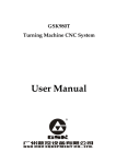
The process from part drawing to part machining is shown below:
CNC machine range and CNC machine tool selection
Workpiece installation in the machine and essential clamp selection
Cutting sequence (Blank selection, tool start position, roughing and the
completion of cutting value and tool path)
Selection for cutting tool and tool clamping and determination for the
installation position in the machine tool
Cutting conditions (Spindle speed, feedrate, and cooling ON/OFF)
Process table
N
G
X
Y
N00
G0
X80
Y20
1
0
N00
2
0
…
…
…
0
X50
Y20
Compile contents of the process table into programs to into the CNC.
The followings describes a part program to be compiled.
2.2
Structure of an NC Program
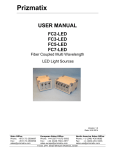
A program includes a main program and subprograms. Normally, the CNC operates
according to the main program. However, when a command edited by the main program calls a
subprogram in the main program, then the CNC performs operations according to the
subprogram. Besides, when the subprogram is commanded to return to the main program, the
CNC performs operations based on the main program’s commands.
3
GSK983Ta Turning CNC System User Manual
The CNC memory can store 191 main programs and subprograms and the CNC system
operates one of them to run the machine tool.
Main program
Subprogram
Command 1
Command 2
Command 1’
Command 2’
Program
command transfer
Chapter 2
Command n
Command n+1
Programming
Main program
command return
Note : As for storage and selection modes of programs, refer to the “CHAPTER FOUR
2.2.1
OPERATION”.
Block
A program is composed of multiple commands, and one group of commands is called a block.
Two blocks are separated by the end code of block, and the block end code is represented by “;”
character in the following explanation of the manual:
For example:
N2 G00 X10.0 Z22.0;
N3 G01 Z10.0 R5.0 F100;
N4 X38.0 K-4.0;
N5 Z0;
Note 1: Character number of a block is not restricted.
Note 2: Block end code:
2.2.2
EIA code is used with CR, ISO code is used with LF.
Word
A block consists of words. A word is composed of an address and its following several digits.
(+/- may be prefixed to a digit).
X
—
1000
Address
Number
Word
An address uses one of letters (from A to Z) to defines meanings of its following digits. The
following table describes addresses and meanings used in the CNC. One address’ meaning is
4
Chapter 2
Programming
different because preparatory functions have different commands.
Function
Address
Meaning
O —— EIA
Program No.
Program number
:—— ISO
Sequence No.
Sequence number
G
Specifies a motion mode (linear, arc ect.)
X,Z,U,W
Coordinate axis movement command
R
Arc radius, corner R
I,K
Coordinate of arc center, chamfering
Feedrate
F,E
Feedrate command, leading
Spindle function
S
Spindle speed command
Tool function
T
Tool number, tool offset number
M
Switch ON/OFF control command on machine side
P,X,U
Dwell time
P
Subprogram number
Preparatory
function
Coordinate
word
Miscellaneous
Dwell
Program no.
designation
Number of
Number of subprogram repetitions, number of canned
L
Repetitions
cycle repetitions
A,D,I,K
Parameter
Sequence no.
Canned cycle parameter
Sequence number for specifying cycle program start
P,Q
designation
Programming
function
Chapter 2
N
and end
The following block can be formed by using these program words:
F
S
T
M
Tool function
Miscellaneous function.
;
Block end code
Preparatory function.
Z
Spindle function
Sequence no.
X
Feedrate
G
Coordinate word
N
In the following example for program table, one row indicates as a block, one grid of a block
indicates as a program word.
Name Test program 1
Date:
Program record
Program no. 0( ; )
N
G
X
Confirm
Programmer:
4321
/
Page1/1
Z
U
W
R/I
K/A/
F/
D
E
S
T
M
P
Q
;
L
;
5
GSK983Ta Turning CNC System User Manual
N10
N11
N12
N13
N14
G5
X220.
Z19
0
0
0.0
G0
X176.
Z13
0
0
2.0
;
G7
U4.
2
0
W2.0
D700
F3
S40
P
Q1
0
0
13
8
G0
Z58.
S60
0
0
0
G0
1
X120.
0
W12.0
N15
Chapter 2
N16
X80.0
N17
N18
N19
;
X86.0
;
F1
5
;
W10.0
;
W10.0
;
W20.0
;
W22.0
;
Programming
G7
P
Q1
0
13
8
N20
2.2.3
;
;
M02
;
Format Input
Each program word composed into a block should be in accorded with the following format. If the
input is variable block format, the number of program word in the block and word number in a
programming word can be changed. It is very convenient in programming, and GSK983Ta CNC
system uses this format.
1) Metric input
RD053
N04· G02·αL+ 053· βL+053·
F032
·
S02
· E034·
ID053KD+ 053
F050
·
T03
·M02
S04
T04
?
2)Inch input
RD044
N04· G02·αL+044· βL+044 ·
F024
·
ID044·KD044
·E016·
F032
S02
·
S04
Note 1: α:X or U;
β:Z or W
Note 2: Address and digit meanings are as shown below:
X
L + 0
5
3
The 3 digits in the following of decimal point
The 5 digits in the front of decimal point
Leading zero can be omitted
With sign
Absolute or incremental value
Address
6
T03
· M02
T04
Chapter 2
I
D 0
5
Programming
3
The 3 digits in the following of decimal point
The 5 digits in the front of decimal point
Leading zero can be omitted
Incremental value with sign
Address
Example:
To move the X axis to 50.123mm at the rapid traverse, the tool move commands are shown below:
G00
X
50
123
The 5 digits in the front of decimal point, the leading zero of 00050 can be omitted.
Even the leading zero can be omitted, G00 can be omitted to G0 (G00 specifies
rapid feedrate)
effective, no alarm.
For example: G01 M03 S200 M08;
M08 enabled, M03 disenabled.
1) G code in each group is also enabled at last.
2) R, I and K are simultaneously commanded in arc command, it is regardless of sequence, and the R is
enabled.
3) E and F are commanded in thread cutting in a same block, the posterior commands are enabled.
4) X or U and Z or W, the posterior one commanded is enabled.
Note 4: F032 and F050 input by metric are shifted with parameter, also F033 and F051, refer to (2.4.4
feedrate 1/10) F032 (input by mm) and F024 (input by inch) are feed input format per rev. F050
(input by mm), F032 (input by inch) are feed input format per min.
Note 5: A, P, Q, L and D have many significations, so the above formats are omitted.
Note 6: Refer to (2.2.4 decimal point input) when inputting by using decimal point.
Note 7: The input values with parameter setting X, Z, O, W, I, K, R and D millimeter can be used with 10
multiple units.
RD052
αL+ 052·βL+052·
(Input in Millimeter)
ID052· KD052
Refer to (Section 2.3.2.3, 10 multiple of input unit).
Note 8: The standard configuration function is S4 bit numeric analog spindle function.
2.2.4
Decimal Point Programming
Numerical values can be entered with a decimal point in this device. A decimal point can be used
when entering a distance, time, or speed. But all addresses have limitation; the position of decimal
point is indicated as the positions of mm, inch, deg and s (second).
Z15.0
Z15mm or Z15inch
F10.0
10mm/r, 10mm/min or 10inch/min, 10inch/r
7
Programming
Note 3: In one block, same address word commands more than two, in fact, the following commands are
Chapter 2
3 digits in the following of the decimal point
GSK983Ta Turning CNC System User Manual
G04 X1.
Dwell 1 second
Decimal points can be specified with the following addresses: X, Z, U, W, I, K, R, E and F.
Note 1: X and U can be input by decimal point, but P cannot (because the P can be employed for sequence
number), when commands dwells
Note 2: The corresponding G code should be commanded prior to the number within one block.
1) G20; (Inch specifying)
X1.0 G04;
X1.0 G04 is equivalent to is not represented to t X10000 G04 when instruct in inch,
the result dwell time is 10s.
G04 X1.0;
It is regarded as G04X1000, dwell time is 1s.
2) G98; (mm/min specifying)
F1.G99;
Specifying F1 G99 into 0.01mm/rev. (G99 is mm/rev.)
Chapter 2
G98: (mm/min specifying)
G99 F1
Specifying G99F100 into 1mm/rev. (G99 is mm/rev.)
Note 3: It is very different with or without decimal point. Note that it is also different to the computer
programming.
Programming
G21; (Specifying mm)
X1.……X1mm
X1……X0.001mm
G20; (Specifying inch)
X1.……X1inch
X1……X0.0001inch
Note 4: The numbers with or without decimal point can be mixed to use.
X1000
Z23.7;
X10.
Z22359;
Note 5: The values following the least setting unit is specified, the values less than the least setting unit
is omitted. When specifying X1.23456 when the metric input is regarded as X1.234, the inch input
is regarded as 1.2345. There is cumulation error when the incremental command occurs. There
no cumulation error but has omittance error when the absolute command occurs. Same, digit can
not over the max. allowance digit.
X1.23456789……it overs 8 digits, alarm occurs; X1.2345678…… it is within 8 digits, the alarm will
not generated, but the value less than the min. setting unit will be striped away.
Note 6: When a number with decimal point is input, A minimum incremental integer is shifted by this
number.
For example: X12.34→X12340 (mm input)
The shifted integer value should be verified with digit.
2.2.5
Max. Command Value
The max. command values for each address are shown below, but, these figures represent limits
on the CNC side, which are totally different from limits on the machine tool side. For example: for the
CNC equipment, the movement value of X axis is 100m (in the occasion of metric), in fact, an actual
stroke along the X axis may be limited within 2m, the feedrate is not changed. The CNC cutting
feedrate can be controlled within 30m/min, and the machine tool actually can be limited within 6m/min.
Refer to the manual and machine tool manual in actual programming. Programmer can perform
programming after fully understanding program limitations.
8
Chapter 2
Table 2.5
Function
Programming
Basis address and ranges of command values (including additional option)
Input in mm
Output in mm
Address
Input in inch
Output in mm
Input in mm
Output in inch
Input in inch
Output in inch
:(IS0)
O (EIA)
N
1~9999
Same as left
Same as left
Same as left
1~9999
Same as left
Same as left
Same as left
G
0~99
Same as left
Same as left
Same as left
X,Z
U,W
I,K
±99999.999 mm
±3937.0078inches
±99999.999mm
±9999.9999inches
R
0~99999.999 mm
0~3937.0078inches
Feed per revolution
Thread leading
F
(1) mm/r
~500.00mm/r
0.0001inches/r
~50.0000inch/r
Feed per revolution,
thread leading
(feedrate 1/10)
(Parameter setting)
F
0.001mm/r
500.000mm/r
~
Feed per minute
F
1
mm/min
15000mm/min
~
Feed per minute
(feedrate 1/10)
(Parameter setting)
F
Thread leading
Program No.
Sequence No.
Preparatory
function
Coordinate word
0~9999.9999inches
0.0001 inches/r ~
50.0000inches/r
0.001 mm/ r ~
500.000mm/ r
Ditto
0.01 inches/min ~
600.00inches/min
1 mm/min ~
15000
mm/min
0.01 inches/min ~
600.00inches/min
0.1
mm/min ~
15000.0mm/min
Ditto
0.1 mm/min ~
15000.0mm/min
Ditto
E
0.001
mm
500.0000mm
0.000001 inches~
9.999999inches
0.0001 mm~
500.0000mm
0.000001 inches~
9.999999inches
E
0.00001~
99.99999mm
Ditto
0.000001~
99.99999mm
Ditto
S
T
0~9999
0~9932
Same as left
Same as left
Same as left
Same as left
Same as left
Same as left
M
0~99
Same as left
Same as left
Same as left
X,U,P
0~99999.999S
Same as left
Same as left
Same as left
P,Q
1~9999
Same as left
Same as left
Same as left
L
1~9999
Same as left
Same as left
Same as left
A
Specifying value
Some
coordinate
word
1~9999
Same as left
Same as left
Same as left
Same as left
Same as left
Same as left
Same as left
Same as left
Same as left
D,I,K
D
~
Note: Feedrate per rev. and thread leading are actually related to spindle speed. F/min. is determined by
the converted speed, and is specified by above-mentioned command. Parameter of Feedrate 1/10 is
rd
the 3 bit of NC No.5.
2.2.6
Program Number
The CNC control can store many programs into the NC memory, program numbers are added to
distinguish from these programs.
Program number definition is shown as below:
O □ □
□
□
(Program number can be from 1 to 9999 )
4 digits
Program performs with a program number, till to M02;, M30; or M99; end.
9
Programming
Ditto
Chapter 2
Thread leading
(feedrate 1/10)
(parameter setting)
Spindle function
Tool function
Miscellaneous
function
Dwell
Designation of a
sequence No.
Number of
repetitions
Angle
Cutting
Parameter value
Times
0~99999.999
mm
0.01 mm/r ~
500.00
mm/r
GSK983Ta Turning CNC System User Manual
O1111……………………………M02;
O2222……………………………M30;
#2222 program
#1111 program
M02 or M30 indicate that the main program ends; M99 indicate that subprogram ends.
O5555………………………………M99;
#5555 subprogram
Chapter 2
Note 1: “:” is replaced “O” when ISO code is performed.
Note 2: At the end of the program, the blocks with optional block skip codes such as /M02;, /M30;, M99 are
disabled .
Note 3: There is no any program number at the beginning of a program, the sequence number of the
program beginning is regarded as the program number; but the NO replaces the program number
Programming
is unallowed.
Note 4: When neither program number nor sequence number is at the beginning of the program, the
program number should be specified when storing to the memory. (Refer to Chapter 4, Section
4.5.15).
Note 5: The subprogram should have program number.
Note 6: Program numbers 9000~9899 are employed by machine tool builder, the user can not use.
Note 7: When selecting with mechanic, the programs 9900~9999 are employed with the data of mechanic.
Note 8:In the end of the program, if there is not M02, M30, M99 command, but with ER(EIA)or %(ISO)
and the next block number, the program end is set by No. 306 bit3(NEOP).
2.2.7
Sequence Number
At the head of a block, a sequence number is specified by a number (1~ 9999) following the
address N with less than 4 digits. Sequence of sequence number can be continuous or not. All blocks
or some blocks with necessity have sequence numbers.
It is suggested that the sequence number should be specified at key position. For example, the
tool change and new tool are performed.
Note 1: In order to be compatible with other NC devices, the sequence number N0 should not be employed.
Note 2: 0 is disabled as program number for some devices, so 0 can not be used for sequence number of
program number.
2.2.8
Optional Block Skip
When a slash followed by a number /n (n=1~9) is specified at the head of block and
corresponding block skip BLOCK SKIP2 switch (optional skip block) is set to 1, the block with /n is
ignored.
When optional skip block switch is set to 0, the block with /n is valid, namely, the operator can
perform the block skip for the block with /n.
1 in /1 can be omitted. Press “Skip” key on the operation panel to determine whether the block is
ignored.
When “Optional skip block 2=1”, the omitted area is shown below:
10
Chapter 2
Programming
;/2N123G01X4………………;N7856
Omittance area
Example:
N100 X100;
N101/2 Z100;
N102/2/3 X200;
N103/3 Z200;
In the above examples, blocks N101 and N102 are skipped when “Optional block skip 2=1”, and
blocks N102 and N103 are skipped when “Optional block skip 3=1”.
Note 1: A slash (/) must be specified at the head of a block, if a slash is placed elsewhere in the block, the
is still enabled.
Note 2: When an optional block skip switch is on, TH and TV checks are made for the skipped portion in
the same way as when the optional block skip switch is off.
When the slash / is specified at the head of a block is read into a cushion, even if the block skip
switch is ON, this block will not be ignored.
Note 4: This function is still enabled during the sequence number searches.
Note 5: This function is disabled when the program is stored, regardless of how block skip switch is set.
Note 6: When the program in the memory is output to the outer PC by communication interface,
regardless of how block skip switch is set, it can be output integrally.
Note 7: Some optional block skip switch may not be used for some machine tools. So please refer to the
machine tool builder manual.
Note 8: When an optional block skip is specified, if multiple optional block skip codes (/) are specified in a
block, 1 in /1 can not be omitted.
Please describe /1 according to the above.
Example:
Error:/ /3G00 X10.0;
Right:/1/3G00 X10.0;
2.3
Dimension Word
The dimension word describes tool movement, composed of movement axis address, its value
indicates move direction and length. The value modification is determined by the absolute and
incremental programming. (Refer to Section 2.3.7)
Dimension word address
X, Z
Basic axis
Parameter for
U, W
R
Meaning
Describing a target position in coordinate system (Absolute programming).
Specifying a move distance (incremental programming). U indicates X axis,
W indicates Z axis.
Specifying an arc radius.
11
Programming
Note 3: The optional block skip is processed when it is transferred from memory to cushion memory.
Chapter 2
information from the slash to EOB code is ignored, however, the information in front of the slash
GSK983Ta Turning CNC System User Manual
arc interpolation
I, K
Specifying a distance (I) or (K) from starting point to arc center along the X
axis or Z axis
For example: U-200.0 tool moves to 200.00 along X axis negative direction from current position.
2.3.1
Controlled Axes
Movement axes of machine tool controlled by CNC system are called Controlled axes. Each
controlled axis is called by the controlling dimension word. There are two controlled axes X and Z.
There are 2 simultaneous controlled axes are specified in a block.
Chapter 2
2.3.1.1
Controlled axes
Simultaneous controlled axes
X, Z
2 pieces
Coordinate axis and movement sign
Programming
If a machine tool offers multiple relations between machine tool coordinate axis and tool
movement sign, severe mess may occurs in a programming. In order to simplify the programming
and guarantee the versatility of the program, the unified criterion (EIARS-267-A&ISO841) is applied
for the coordinate system of CNC machine tool and direction name, and the linear feed coordinate
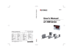
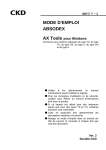
axes are indicated by X, Y and Z, they are normally called coordinate axes. The relationships among
X, Y and Z are determined by the right hand rule, see Fig.3.1-1:
Fig.3.1-1
Machine tool coordinate axis and direction
A thumb direction is positive direction of X axis, a forefinger is positive direction of Y and a middle
finger is positive direction of Z.
Circle feed coordinate axes rotated around with the X, Y and Z axes are separately indicated with
A, B and C in terms of the right hand rotation rule, see the figure. The thumb direction is +X, +Y and
+Z, and the direction of forefinger and middle finger are the circle feed movement +A, +B and +C
directions.
Feed movement of CNC machine tool, some are operated by the spindle drives tool, and some
are operated by the workpiece on the worktable. The abovementioned + coordinate axes are
supposed to the workpiece stops, the tool is feed movement direction which is related to the
12
Chapter 2
Programming
workpiece. If the workpiece movement is specified, it is indicated with character“’”In terms of relation
of movement, the + workpiece movement direction is reversed to the + tool movement, that is:
+X =-X′, +Y =-Y′, +Z =-Z′,
+A =-A′, +B =-B′, +C =-C′
In a similar way, negative directions of both movements are reversed each other.
Chapter 2
Programming
Direction on the machine tool coordinate axis is determined by the type and component layout of
each part of the machine tool. For the turning machine:
—— Z axis is identical with the spindle axial line, the distance between parts and tool is enlarged
by movement along + Z axis direction;
—— X axis is vertical to Z axis, which is corresponding to revolving tool post movement, the
distance between parts and tool is enlarged by movement along + X axis direction;
—— Y axis (it is nominal) consists of right hand coordinate system rule with X axis and Z axis.
Note the following items during programming.
a) Program must refer the standard coordinate system (Right hand square coordinate).
b) Supposing the workpiece is not move during programming, the tool moves around the
tool.
2.3.2
Increment system
Increment system is determined by the following two elements.
2.3.2.1
The least input increment (input unit))
The minimum units are specified by the tool movement, these minimum units are specified by
mm/inch.
13
GSK983Ta Turning CNC System User Manual
Minimum movement unit (output unit)
2.3.2.2
Minimum movement unit of machine tool is specified, any group of the following can be
employed by using mm, inch or degree units.
The least input increment
The least movement unit
Input in mm, output in mm
0.001mm
0.001mm
Input in inch, output in mm
0.0001inch
0.001mm
Input in mm, output in inch
0.001mm
0.0001 inch
Input in inch, output in inch
0.0001inch
0.0001 inch
Chapter 2
Specifying the diameter, the min. movement unit of X axis is also a diameter value.
Whether the least movement unit of machine tool is either 0.001mm or 0.0001inch is determined
by the set parameter in advance (SCW) #5.0.
Programming
Whether the least input increment is either 0.001mm or 0.0001 inch is determined by the G code
or set by MDI.
G20
The least input increment 0.0001 inch
G21
The least input increment 0.001mm
The mode of power on is still that of G20 and G21 before power on.
2.3.2.3
10-fold input unit magnification
The least input increment input in mm can be changed into 0.01mm by the parameter #5.1(MIC).
The least input increment input in inch is not changed.
Address
Input unit
Input in mm
Input in inch
0.0001 inch
Dimension word
X,Z,U,W,R,I,K
0.01mm
Dwell time
X,P,U
0.01s
Parameter
D
0.01mm
0.001s
0.0001 inch
The following items are not be changed:
(a) Different input
(b) Display unit
(c) Range for max. command value
(d) Units for step and manual feed
(e) Offset input
(f) Others
Note 1: The input unit in the manual is either 0.0001 inch or 0.001mm.
Note 2: When input in metric is performed, the display unit is 0.01mm by setting the parameter #5.2 (MDL).
14
Chapter 2
2.3.3
Programming
Maximum Stroke
The maximum stroke can be specified in the system, see the following table:
Input in mm
Input in inch
Input in mm
Input in inch
Output in mm
Output in mm
Output in inch
Output in inch
±99999.999mm
±3937.0078inch
±99999.999mm
±9999.9999 inch
Note: The above stroke should be changed with the different of machine tool, please refer to the
machine tool manufacture’s manual.
2.3.4
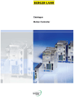
Program Origin and Coordinate System
program origin is a random point at the workpiece.
For example, X axis origin is specified at the center of workpiece, and Z axis origin is specified at
Programming
the left surface of workpiece terminal surface.
See Fig.3.4-1
Program
origin
Fig. 3.4-1
Program origin
This coordinate system is called workpiece coordinate system.
There are two coordinate systems, one is left hand, and the other is right hand. Right hand
coordinate system is employed in the manual.
(Right hand coordinate system)
2.3.5
Chapter 2
The program origin and coordinate system should be confirmed in programming. Normally, the
(Left hand coordinate system)
Coordinate System and Machining Starting point
Workpiece coordinate system should be memorized to CNC during programming, the tool moves
15
GSK983Ta Turning CNC System User Manual
and a program operates should be performed from a starting point. But, the starting point and tool
coordinate value should be offered by using G50.
Start
Chapter 2
Origin
Fig. 3.4-2
G50 Workpiece coordinate system setting
Programming
Workpiece coordinate system of NC is specified by G50 X αZβ command.
Firstly, X=α and Z=β are applied to CNC, this command is offered at the head of a program or,
the command is offered from MDI when the tool is at start position. (Refer to the CHAPTER FOUR,
section 4.4.9 MDI run mode).
It is very easy to position to the starting point if the workpiece coordinate system is firstly
confirmed:
(1) MDI/LCD display panel, command G00X αZβ; (G00 is positioning command).
(2) Manual feed moves the tool to X=α and Z=β from viewing position.
Workpiece coordinate system is determined by the following modes.
(Mode 1) Performing G50 in MDI mode.
Workpiece
coordinate
system origin
When a tool is positioned at the origin of workpiece coordinate system, the following commands
can be specified in MDI mode after positioning.
G50 X0 Z0;
16
Chapter 2
Programming
X
Side B
p
α
Side A
Chapter 2
Workpiece coordinate
system zero point
Usually, it is impossible for the tool to position to the origin.
So, the tool is at the P position of workpiece in the abovementioned figure. Commands are
performed in MDI mode below:
Programming
G50 XαZβ; the workpiece coordinate system is correspondingly set.
However, hard position of P point is the reason, so the following steps should be performed:
Manually cut Side A of workpiece.
The tool leaves and the spindle stops along the X axis, the Z axis does not move.
Measure the distance of “β” and specify G50 Zβ in MDI mode, press the DATA INPUT and
CYCLE START keys to set the workpiece coordinate system into NC in MDI mode. The measure
method of α value is similar to β.
(When side A and B are cut with a same tool, the offset value is 0; when different tools are
employed, the difference between two tools is regarded as offset value to store. Offset value measure,
see Section 2.6.5).
(Method 2) The coordinate system is set after positioning to the starting point is performed.
When the tool is positioned to the starting point, the following steps should be performed:
(1) Cut manually side A of workpiece.
(2) Z axis does not move, and the tool leaves from the X axis and the spindle rotation stops.
(3) Clear the relative coordinate value of Z axis (address W), (see Section 4.4.6).
(4) Measure the distance of “δ” in the following figure.
(5) Cut manually side B of workpiece.
17
GSK983Ta Turning CNC System User Manual
Side B
Start
point
Origin
Chapter 2
Side A
(6) X axis does not moves, the tool leaves from the Z axis and the spindle rotation stops.
Programming
(7) Clear the relative coordinate value of X axis (Address U) (see Section 4.4.6).
(8) Measure the distance of “r” above figure.
(9) View relative coordinate display and move the tool to X=α-r,Z=β-δcoordinate position at
the same time.
α and β are coordinate value of starting point.
If G50 XαZβ is specified at the beginning of program, the coordinate system is set when the
program is executed (in actual machining, offset setting is the same as that of method 1 when tool
change is performed).
(Method 3) The reference point is regarded as the starting point at the head of program, and the
coordinate system setting is performed.
If tool nose
moves,
using
the tool offset
Starting point
(Reference point)
Origin
When reference point returns, the tool starting point is coincident with reference point. The
following steps are the same as of method 2, the tool nose can not be positioned at the reference
point, but a standard tool can do so. Error of both can be set by tool offset value offset (see Section
2.6) or moving the workpiece coordinate system (see Section 2.5.10).
18
Chapter 2
Programming
(Method 4) Automatic coordinate system setting.
When the corresponding parameter is set, a coordinate system is automatically set after the
reference point return is performed.
Coordinate values α and β are separately set by parameter #375 and #376 when input in inch is
performed(when input in inch,they are set by the parameter #379 and #380).
The tool nose can not be positioned at the reference point, so, tool position can be compensated
by using tool offset function (see the Section 2.6.1) or workpiece coordinate system movement
function (see Section 2.5.10).
Reference Point
The reference point is a fixed position on the machine tool. The reference point return function is
to perform the tool to return the reference point.
but it can be started from the reference point accordingly. In this case, the reference point is a certain
point on the machine tool, and the point corresponds to the zero of the workpiece coordinate system,
and makes the program finish the machining normally. G50 command should be commanded when
the tool returns reference point to set the workpiece coordinate system.
2.3.7
Absolute Command and Incremental Command
Command for B->A
Command
mode
Address
in the following
figure
Absolute
Specifying
command
workpiece coordinate system
Z (coordinate value of Z axis)
Specifying the distance from
U (distance of X axis)
start to end points
W (distance of Z axis)
Incremental
command
end
point
on
X (coordinate value of X axis)
X40.0 Z5.0;
U20.0 W-40.0
19
Programming
A program can not be randomly started from a certain position on workpiece coordinate system,
Chapter 2
2.3.6
GSK983Ta Turning CNC System User Manual
Program
origin
Chapter 2
Note 1: Absolute command and incremental command are shared with the same block; the above
Programming
example can be specified by the following command: X40.0 W-40.0;
Note 2: When X and U or W and Z are shared with the same block, the later specified is enabled.
2.3.8
Specifying Diameter and Radius
Usually, the cross-section of workpiece is round when NC turning machine is programming, so,
two specifying dimension methods including diameter and radius values can be employed.
X axis
Z axis
Diameter command
Radius command
When the diameter is specified, it is referred to as diameter command; when the radius is
specified, it is referred to as radius command. The radius program can be performed when the radius
command is selected; when the diameter command is employed, some items should be noticed in
the following table:
Item
Caution
Command of Z axis
Specifying diameter or radius irrelative
Command of X axis
Specifying with diameter
Incremental command by using address U
Coordinate system setting (G50)
X value of tool position offset
20
Specifying diameter value, from B to A, D1 to D2 in
the above figure
Specifying X axis coordinate value with diameter
Setting diameter or radius value with parameter
#8.7.
Chapter 2
Programming
Parameter of cutting depth by using G90-G94 and
Specifying radius value
G70-G76 along with X axis. (D, I and K)
Radius specifying for arc interpolation (R, I and K)
Specifying with radius
Feedrate along with X axis direction
Radius change/rev.; radius change/min.
X axis position
Diameter value display
Note 1: In the following explanation, command programming is not specified (diameter or radius). But,
value of X axis is indicated with diameter value when the diameter command is performed. Value
of X axis is indicated with radius value when the radius command is performed.
Note 2: When diameter value is used in tool offset and tool position offset value is changed to cut the
For example: Offset value changes for 10mm, and outer diameter changes 10mm at the diameter
value, when tool keeps invariable.
Note 3: Tool position offset uses diameter value, the tool offset value can be set to the tool length value.
Programming
2.4
Feed Function
2.4.1
Chapter 2
outer diameter, the outer diameter is then changed with diameter value.
Rapid Traverse Rate
In rapid traverse mode, each axis on the machine tool moves at the specified rate.
Normally, the rapid traverse rate is confirmed and set by the machine tool builder before
delivering the goods (set by parameter #92 RPDFX, #93 RPDFZ).
When each axis of machine tool separately runs, movement time of each axis from starting point
to end point is different.
For example, when the rapid traverse rate of X and Z axes are 500inch/min and 800inch /min
separately and their commands are shown below:
G00 U200.0 W300.0;
Movement time of X axis on the machine tool from the starting point is 12 seconds, Z axis is 22.5
seconds. If X axis value is specified with radius programming, the finished movement time is 24
seconds.
The tool path is shown below:
(Diameter command)
End point
Starting
i t
21
GSK983Ta Turning CNC System User Manual
The switch on the machine operation panel can control override of rapid feedrate. (F0, 25%, 50%
and 100%) F0 is set by parameter #13 RPDEL, and its unit is not indicated with (%), but indicated
with mm/min. or inch/min.
2.4.2
Cutting feedrate
Feedrate per revolution or minute is determined by the digits followed by F.
Feed value for 1 min.
Move value for 1 rev.
1分钟的移动量
1转的移动量
Chapter 2
Programming
Feedrate/rev.
每转进给
(mm/rev,inch/rev)
每分进给
Feedrate/min.
(mm/min,inch/min)
Meaning
Feed/min.
Feed/rev.
Tool feed distance/min.
Tool feed distance/rev.
F
F
G98
G99
1~15,000mm/min
0.01~500.00mm/r
(F1~F15000)
(F1~F50000)
0.01~600.00inch/min
0.0001~50.000 inch /r
(F1~F60000)
(F1~F500000)
Programming address
G code setting
Range
Input in Metric
Input in Inch
Cutting feedrate is clamped at fixed speed. This value (Clamping
Clamping value
value) is specified by the machine tool builder (Speed after the override
is also clamped).
Override
10%/step, modifying from 0~200%.
The clamp value is specified by mm/min or inch/min. Cutting feedrate can be converted into
mm/min or inch/min by the following formula when feed/rev is performed.
fm=fr×R
fm: Feed/min. (mm/min or inch/min)
fr: Feed/rev. (mm/r or inch/r)
R: Spindle speed (r/min)
Note 1: G98 and G99 are modal. When one of them is commanded, the command is always enabled before
the other command is specified.
Note 2: The specified feedrate is set to the error within ±2% for NC computer, other than the
acceleration/deceleration.
Note 3: Position encoder should be installed in spindle if the feedrate is feed/rev. when programming.
22
Chapter 2
Programming
Note 4: F code input is allowed up to 7 digits. But the feedrate can not exceed the clamp value.
Note 5: If the number of revolution for position encoder is below 1, the cutting feedrate is uneven. So, the
lower of the spindle speed is, the more uneven of cutting speed is.
2.4.3
Thread Lead
The digits following address F and E specifies a lead in thread cutting. Thread cutting is specified
by G32, G76 or G92.
G code
Meaning
G32
Thread cutting
Thread cutting cycle
Chapter 2
G92
(Single canned cycle)
G76
Thread cutting cycle
(Complex canned cycle)
Programming
Range of thread length, see the following:
Address
Input in Metric
Input in Inch
F
0.01 mm ~500.00mm
0.001 inch ~50.0000inch
E
0.0001 mm ~500.0000mm
0.000001 inch ~9.999999inch
Spindle speed limitation is as shown below:
R≤
Max.feedrate
(R ≥ 1)
Thread lead length
R: Spindle speed (r/min)
Lead: mm or inch
Max. feedrate: mm/min or inches/min
Max. feedrate is limited by least one of the following speed: (1) feederate per minute of Max.
command speed; (2) Max. speed value is limited by motor or machine tool.
Note 1: The spindle speed is read from the position encoder installed on the spindle. Feed/min. is
converted, and the machine tool moves with the converted speed.
Note 2: Speed override is disabled for the converted speed.
Note 3: The converted speed is clamped.
Address F specifies the thread lead, and the address F is the same as F used to specify feed/min.
or feed/rev.
Address E is only used for specifying the thread lead.
The last one of thread leads specified by E and F is enabled.
When thread cutting is not processed, for feed/min and feed/rev, F code keeps enabled
regardless of E code;
In thread cutting block, when E and F are in the same block, the latter is valid.
Example (program using the following
sequence)
Enabled feedrate/ thread lead
23
GSK983Ta Turning CNC System User Manual
Chapter 2
2.4.4
G01Z……………..F100;
F100
G32Z…………….;
F100
G32Z…………….E200;
E200
G01Z…………….;
F100
Z…………….F300;
F300
G32Z……………;
F300
G32Z…………….F100E200;
E200
G32Z…………….E200F100;
F100
Feedrate 1/10
Feedrate input in mm can be shifted to the min. unit 1/10 by setting the parameter (FMIC).
Min. input incremental
Feed/min.
0.1mm/min
Feed/rev.
0.001mm/r
Thread lead F command
0.001mm
Thread lead E command
0.00001mm
Programming
Item
2.4.5
Range
F1~F150.000
(0.1 mm/min ~15000.0mm/min)
F1~F500000
(0.001 mm/r ~500.000mm/r)
F1~F500.000
(0.001 mm ~500.000mm)
E1~E9999999
(0.0001 mm ~99.99999mm)
Automatic Acceleration/Deceleration
A time constant automatically produces acceleration or deceleration to avoid the mechanical
system trembles, during starting or stopping. So, the acceleration/deceleration is not considered
when a programming is performed.
A pointed corner can not be machined due to automatic acceleration/deceleration. A dwell
command (G04) should be inserted between two blocks if you machine a pointed corner.
Dwell command inserts
Programmed path
Actual tool path
If a dwell command is inserted, the actual tool path is consistent with programmed path. The
faster the feedrate is and the longer the acceleration/deceleration time is, the more the corner error is.
24
Chapter 2
Programming
Note 1: NC processes between blocks, as shown below:
Previous block
Positioning
Cutting feed
Unmovable
Positioning
X
X
X
Cutting feed
X
O
X
Unmovable
X
X
X
New block
X: Command speed is decelerated to zero; the next block is then performed again.
O: The following block is orderly performed; the feedrate is not much changer.
Note 2: Acceleration/deceleration is separately performed to each axis (X and Z axes), and the feedrate of
each axis is changed between blocks, so, the actual tool path is inconsistent with programmed
direction acceleration produces, the actual tool path as shown below:
Actual tool path
The actual arc radius is less than the programmed arc radius in arc interpolation (see the D4.3 in appendix four).
In the occasion of machine tool allowance, and In order to reduce this error, the small acceleration/deceleration time
constant of cutting feed is employed.
2.5
Preparatory Function (G Function)
Two digits following address G determines the meaning of the command for the concerned block.
G codes are divided into the following two types.
Type
Meaning
One-shot G code
The G code is effective only in the block in which it is specified.
The G code is effective after specifying once until another G code of the same
Modal G code
group is replaced.
For example; G01 and G00 are modal G codes in group 01.
G01
G00
X
;
Z
;
X
;
Z
;
G01 is effective in this range.
There are 3 series G codes. One is standard G code; the other is special G code B/C. Two
selections of the codes are set by parameter #7.5 (GSP). This manual uses standard G code. Special
25
Programming
Programmed
path
Chapter 2
path. For example, a tool is only decelerated to feedrate along X axis in a block, here, the Z axis
GSK983Ta Turning CNC System User Manual
G code with same function and standard G code are indicated in the following table.
G90 and G91 are different. G90 indicates absolute command (The used X and Z are same with
standard X and Z in G90 mode), and G91 indicates incremental command (The used X and Z are
same with standard U and W in G91 mode) in special G codes. But, when the command is input in
MDI mode, in G90/G91 mode, the address X and Z are indicated as absolute command, U and W are
indicated as incremental command.
Special G codes are employed, the address U and W are same with standard time, and they
are indicated as incremental move distance also, even if the G90 address is applied.
Chapter 2
Standard G
Special G
Special G
code
code B
code C
Group
Programming
☆G00
☆G00
☆G00
Positioning (feedrate rapidly)
☆G01
☆G01
☆G01
G02
G02
G02
G03
G03
G03
Arc interpolation CCW
G04
G04
G04
Dwell
G07
G07
G07
G10
G10
G10
G20
G20
G20
G21
G21
G21
G22
G22
G22
G23
G23
G23
G27
G27
G27
Reference point return check
G28
G28
G28
Reference point return
G29
G29
G29
G30
G30
G30
Return to the 2nd reference point
G31
G31
G31
SKIP function
G32
G33
G33
G34
G34
G34
G36
G36
G36
G37
G37
G37
G40
G40
G40
G41
G41
G41
G42
G42
G42
Tool nose radius compensation -Right
G50
G92
G92
Coordinate system setting
01
00
G65
G65
G65
G66
G66
G66
G67
G67
G67
G68
G68
G68
G69
G69
G69
G70
G70
G70
G71
G71
G71
Linear interpolation (cutting feed)
Arc interpolation CW
SIN curve control for feedrate
Offset setting
06
04
00
01
00
Input in inch
Input in metric
Memory stroke limit ON
Memory stroke limit OFF
Returning from reference point
Thread cutting in linear and taper
Leading thread cutting changeably
Automatic tool X compensation
Automatic tool Z compensation
Tool nose radius compensation cancel
07
00
26
Function
Tool nose radius compensation -Left
Spindle max. speed setting
User macro program non-modal calling
12
13
00
User macro program modal calling
User macro program modal cancel
Double tool-post image ON
Double tool-post image OFF
Finishing cycle
Outer diameter roughing cycle
Chapter 2
Programming
G72
G72
G74
Flat end roughing cycle
G73
G73
G75
Closed-loop cutting cycle
G74
G74
G76
Flat end groove cycle (Z axis)
G75
G75
G77
Outer diameter groove cycle (X axis)
G76
G76
G78
Thread cutting cycle
G90
G77
G20
Single canned cutting cycle A
G92
G78
G21
G94
G79
G24
G96
G96
☆G96
☆G97
☆G97
☆G97
01
Thread cycle
Single canned cutting cycle B
Constant surface speed control
02
Constant
surface
speed
control
☆G94
☆G94
☆G99
☆G95
☆G95
☆G90
☆G90
☆G91
☆G91
Feed/min.
05
03
Feed/rev.
Absolute value command
Incremental value command
Note 1: A G codes with the sign of ☆ is the start G code of each group. Namely, A G code can be
established after the resetting key is controlled, when the power is turned on or the parameter for
described start G code is enabled. As for G22 and G23, G22 is selected when the power is turned
on. G22 or G23 is a mode before resetting (one of them is effective before resetting).
As for the G00 and G01, G98 and G99 or G90 and G91; the G code in the initial state can be
selected by setting parameter #7.
G20 or G21 is the state of before the power is turned off or the resetting key is controlled.
Note 2: G code in 00 groups is not modal. They are effective only in the programmed block.
Note 3: When a code does not display in the above table in block or a G code without a definition and a
selection is specified, the alarm No. 010 occurs. But, G60 and G61 may not alarm.
Note 4: Provide that some G codes are not share the same group; they can be described in a same block.
When some G codes in the same group are described, the last one is effective.
Note 5: G codes are shown one of them in terms of group.
2.5.1
Positioning(G00)
Function: Tool in the position of coordinate position (X, Z) or from the current position is rapidly
traversed in terms of the specified distance along each axis separately.
Format: G00 X(U)—Z(W)—;
27
Programming
☆G98
Chapter 2
cancel
GSK983Ta Turning CNC System User Manual
X axis
(Diameter
specifying)
X (Diameter specifying)
Z axis
Chapter 2
Programming
Unit: Inch
(Diameter programming) G00 X4.0 Z5.6; or G00 U-6.0 W-3.05;
Note 1: G00 rapid traverse rate of X, Z axis can be separately set by modifying parameter #92 and #93
by the machine tool builder . Rapid traverse rate can not specified by address F.
Tool is accelerated in the start of block till to the predictive speed in the mode of G00 positioning.
And it is decelerated to 0 till to the end of block. In-position check can be set according to the
parameter #6.5 (CINP), ensure that the next block executes after it is in the mode of in-position.
Note 2: “In-position” means that the feed axis motor reaches the range for specifying end position (this
range is determined by setting parameter #70 and #71 according to the actual need by machine
tool builder).
2.5.2
Linear Interpolation(G01)
Function: G01 Linear interpolation moves the tool to the position of X, Z at the speed specified by
F in workpiece system, or, the current position moves to the position specified with U, W
values.
Format: G01 X(U)—— Z(W)—— F——;
(Diameter programming) G01 X4.0 Z2.01 F2.0 or G01 U2.0 W-2.59 F2.0;
(See the figure)
Feedrate specified by address F is the speed which tool moves along linear.
If feederate override is 0, the feedrate is 0, and the diagnosis parameter #700.4 is 1.
Note 1: feedrate of each axis, see the following:
28
Chapter 2
Feedrate along X axis:
Programming
Lx
F
L
Lz
Fz =
F
L
Fx =
Feedrate along Z axis:
Thereinto: F: Feedrate
L: Movement distance
Lx: Movement distance along X axis
Lz: Movement distance along Z axis
Chapter 2
Programming
Unit: inch
2.5.3
Chamfering and Corner R
The following chamfering and corner can be simply inserted between two blocks.
Item
Command
Tool movement
G01 Z(W)b I±i;
In the right figure, tool moves to
Chamfering
Z→X
point
b
is
specified
with
incremental or absolute command
G01 X(U)b K±k;
X→Z
point
b
is
specified
Start
Moving from a to d till c
(-i is the movement of –X)
Start
Start
In the right figure, tool moves to
Chamfering
Moving from a to d till to c
(-i is the movement of –X)
with
incremental or absolute command
Moving from a to d till to c
(-k is the movement of –Z)
29
GSK983Ta Turning CNC System User Manual
G01 Z(W)b R±r;
In the right figure, tool moves to
point
Corner R
b
is
specified
with
incremental or absolute command
Z→X
Start
(-r is the movement of –X)
Moving from a to d till to c
G01 X(U)b
R±r;
Chapter 2
Start
In the right figure, tool moves to
Corner R
X→Z
point
b
is
specified
with
(-r is the movement of –Z)
incremental or absolute command
Moving from a to d till to c
Programming
I and K are always specified with the radius
Unit: mm
(Diameter programming)
N0
G50 X26.8 Z53.0; (point A)
N1
G1 Z27.0 R0.6 F100;(point B)
N2
X86.0 K-0.3;
(point C)
N3
Z0;
(point D)
Note 1: As for chamfering or corner R should be specified with G01 move along X or Z axis. Next block
should vertical to the single command of X or Z axis.
Note 2: Alarm may generate in the following conditions.
1) When I or K or R is employed, X and Z axes are simultaneously specified with G01 mode. (Alarm
No.054)
2) Two of I, K and R in same block are specified with G01 mode. (Alarm No. 053)
30
Chapter 2
Programming
3) X and I or Z and K are simultaneously specified with G01 mode. (Alarm No.056)
4) In the block, the chamfering or corner R is specified, the movement distance along X and Z are
less than the chamfering or corner R. (Alarm no.055)
5) The block which after a block is specified with chamfering or corner R, its movement without
specifying is vertical to G01 of the previous block. (Alarm no.G51)
6) In the block, the chamfering or corner R is specified, its movement direction is incorrect (Alarm
No.052).
Note 3: In single block, the tool moves to the chamfering and corner R position which have finish
executing the command in the block, and stops.
Note 4: Chamfering and corner R can not be used for the block of thread cutting.
Figure Dimension Input
The linear angle such as chamfering, corner R and other dimension value on the machine figure
can be directly entered when programming. Furthermore, chamfering and corner can be inserted
Programming
between the linear of random angle.
For example:
Starting
X(x2)Z(z2),C(c1)
;
X(x3)Z(z3),R(r2);
X(x4)Z(z4);
or
A(a1),C(c1);
X(x3)Z(z3)A(a2),R(r2);
X(x4)Z(z4);
Note 1: A straight line is specified, it is necessary to specify one or two of X (U), Z (W) and A. A straight
line should be specified at the beginning of next block if only one is specified. When chamfering
and corner are specified, they should be separated by “,”, such as: C_, R_.
Command
Chapter 2
2.5.4
Tool movement
31
GSK983Ta Turning CNC System User Manual
1
X2
(Z2
2
A1
;
X3
;
Z3
A2
;
X2
Z2
,R1
X3
Z3
;
Chapter 2
)A
Programming
3
;
or
4
A1
,R1
X3
Z3
A2
X2
Z2
,C1
X3
Z3
;
;
;
;
or
5
A1
,C1
X3
Z3
A2
X2
Z2
,R1
;
X3
Z3
,R2
;
X4
Z4
;
;
;
or
6
A1
,R1
X3
Z3
A2
X4
Z4
;
X2
Z2
,C1
;
X3
Z3
,C2
;
X4
Z4
;
;
,R2
;
or
32
A1
,C1
X3
Z3
A2
X4
Z4
;
;
,C2
;
Chapter 2
7
X2
Z2
,R1
;
X3
Z3
,C2
;
X4
Z4
;
Programming
or
8
A1
,R1
X3
Z3
A2
X4
Z4
;
X2
Z2
,C1
;
X3
Z3
,R2
;
X4
Z4
;
;
,C2
;
Chapter 2
or
A1
,C1
X3
Z3
A2
X4
Z4
;
;
,R2
;
Programming
(Program example) specifying diameter, input in metric
X
N7
R15
N6
R20
N5
N4
R6
N3
N2
Z φ60φ100 φ300
起点
Start
1×45°
10°
30
22°
180
单位:mm
Unit:
mm
N001 G50 X0.0 Z0.0;
N002 G01 X60.0 A90.0,C1.0 F80;
N003 Z-30.0 A180.0,R6.0;
N004 X100.0 A90.0;
N005 A170.0,R20.0;
N006 X300.0 Z-180.0 A112.0,R15.0;
N007 Z-230.0 A180.0;
Note 2: The command uses the figure dimension input directly only when it runs in Auto mode.
Note 3: In the block, the figure dimension is directly entered the command, or between two blocks which
serial figure dimension is entered directly, the following G codes can not be employed.
①
G codes of 00 group (Command other than G04)
②
G02, G03, G90, G92 and G94
Note 4: Corner R can not be inserted during thread cutting.
Note 5: Chamfering of 2.5.3, command of corner R, the chamfering of figure dimension directly input and
corner R can not be employed simultaneously.
33
GSK983Ta Turning CNC System User Manual
Note 6: The edge command of figure dimension enters directly, if the end point of previous block is
determined by figure dimension of next block, single block can not be executed, however, the
feed hold can be ran during the previous block execution.
Note 7: In the following block, the delimitation angle of intersection calculation is performed to ±1°.
(The movement value gained by using intersection point calculation is over.)
X(u)——A——; (If an angle A is specified within 0±1°. Alarm may be generated within 180°±1°)
Z(w)——A——; (If an angle A is specified within 90±1°. Alarm may be generated within 270°±1°).
Note 8: The angle difference between two straight lines is less than ±1°, the alarm occurs when intersection
point calculation is performed.
Note 9: Chamfering or corner R is effective when the angle between two straight lines is less than ±1°.
Note 10: A next block of that the block is only specified by the angle, the seat command (absolute value) and
Chapter 2
angle command should be specified simultaneously.
For example:
N1
X——A——, R——;
As for N3 block, the coordinate and angle commands are
simultaneously specified.
Programming
N2 A——;
N3 X——Z——A——;
Note 11: As for the II type of complex canned cycle (G71, G72), in the direction of cutting, chamfering or
corner of intersection point between blocks can not be performed. If G70 is used to perform the
block with figure dimension input directly command, No.066 alarm occurs.
Cutting
direction
R alarm in this corner
2.5.5
Arc Interpolation(G02,G03)
Function: The following command indicate the tool movement along the arc. The commands are
shown below:
Format:G02
I____ K____
X(U)___ Z(W)___
F____
G03
Content
1
2
3
34
R ____
Command
Meaning
G02
CW
G03
CCW
End point position
X,Z
End position in workpiece coordinate system
Distance to end point
U,W
Distance from start to end point
Distance from start to center
I,K
Distance from start to center (Radius specifying)
Arc radius
R
Arc radius, arc within 180° (Radius specifying)
Revolution direction
Chapter 2
4
Feedrate
F
Programming
Feedrate along arc
The direction of CW or CCW applies when the coordinate system is in right or left hand.
Chapter 2
Right coordinate system
Left coordinate system
G02 X(U)——Z(W)——I——K——F——; (Diameter programming)
Programming
X axis
End point
Starting
Z axis
G03 X(U)——Z(W)——I——K——F——; (Diameter specifying)
X axis
Z axis
G02 X(U)——Z(W)——R——F——; (Diameter specifying)
35
GSK983Ta Turning CNC System User Manual
Arc center
X axis
End point
Starting
Z
axis
Chapter 2
(Diameter programming)
G02 X5.0 Z3.0 I2.5 F0.03;
Programming
Or
G02 U2.0 W-2.0 I2.5 F0.03;
or
G02 X5.0 Z3.0 R2.5 F0.03;
or
G02 U2.0 W-2.0 R2.5 F0.03;
ra
di
us
X
5.0 diameter
2.
5
1.5
1.0
Unit: inch
Z
3.0
5.0
Note 1: This word can be omitted, when I or K is zero.
Note 2: I and K separately specified the distance from the start to center along X and Z axes. The sign should
be considered.
X
End point
End point
k
G03
Start point
Start point
i
Center
of circle
k
36
i
G02
Center
of circle
Z
Chapter 2
Programming
Start
point
Center
End point
by X and Z are same with the starting point, the center is indicated by address I and (or) K, that is a
Chapter 2
Note 3: In programming, when the X, Z, U and W are all omitted, or U and W are zero or the position specified
round of 360° is specified.
specified when the arc is more than 180°.
So: G02 R——; and G03 R——; are not specify the whole round, but arc of 0° does. So, the tool not
moves.
Note 5: When address R value specified is less than the half distance from start to end point(including R=0),
R is omitted, and a half round is generated. If R is negative, No.023 alarm occurs.
Note 6: When programming with I and K, and the end point is not on the arc, the tool moves in terms of the
following figure.
(I)
In arc command, end point of two axes is coordinate, one of them is on the arc, after tool reaches the
coordinate value of the axis end, move directly to another axis end coordinate values by linear mode.
X
Z
End point
r
I
Start point K
Center
of circle
(II)
In arc command block, when end point of two axes are not on the arc, the arc path formed
by
corresponding I and K value is firstly performed, and then move to the end point position with nonlinear
movement, the results are shown below:
37
Programming
For example: G02 I——;
Note 4: An arc within 180° can be specified, when address R is employed in programming, and it is can not be
GSK983Ta Turning CNC System User Manual
X
Z
End point
r
Start point
Center of circle
Note 7: Feedrate can be specified using address F in arc interpolation, see 2.4.2, the error of corresponding
Chapter 2
actual feedrate is within ±2%. The feedrate performs along the arc after tool nose compensation
is executed.
Note 8: When I, K and R are specified simultaneously, R is enabled, but I and K are omitted.
Note 9: I and K are specified zero arc, tool straightly moves from start to end using G01 mode.
Programming
2.5.6
Feedrate for SIN Curve Control(G07)
Function: An axis in arc plane is not moved during arc cutting command, the interpolation
performs only (it is regarded as imaginary axis) along the feedrate of axis, another feedrate of axis
SIN curve change is formed.
Format:G07α0; (α is regarded as imaginary axis)
G07α1; (α is regarded as movement axis)
Specifying as follows:
G07 Z0; ……Z axis is set to an imaginary axis.
G02 X0 Z0 I10.0 F4; ……Feedrate of X axis changes with SIN curve.
G07 Z1; …… Cancel imaginary Z axis.
Note 1: The imaginary axis is only enabled for automatic operation. It is disabled for manual. That is
movement.
Note 2: Inter-lock, stroke limit and outer deceleration are also effective to imaginary axis.
Note 3: The MPG interruption insert is also effective for imaginary axis, this axis is executed as MPG
interruption insert part. Diagnosis #805 and #806 are separately the insert amount of X and Z axis.
38
Chapter 2
2.5.7
2.5.7.1
Programming
Thread Cutting(G32,G34)
Linear, Taper Thread Cutting(G32)
Function: The straight, taper and surface threads cutting can be performed by the command
G32.
Chapter 2
Straight threads
Surface threads
Taper threads
command as follows:
The coordinate position (X, Z) in the workpiece coordinate system is specified the end point or it
is specified the distance from start to end points (U, W).
Format: G32 X(u)——Z(w)——F——;
G32 X(u)——Z(w)——E
Lead length
X axis
End
Start
Z axis
In general, thread cutting is repeated along the same tool path (including from rough cutting to
finish cutting). Since thread cutting starts when the position coder mounted on the spindle outputs a
1-turn signal, so, thread cutting is started at a fixed point. Tool path on the workpiece is unchanged for
repeated thread cutting. Note that the spindle speed must remain constant from rough cutting through
finish cutting. If not, incorrect thread lead will occur.
39
Programming
Values followed with F and E are directly led to perform the thread cutting. Thread cutting
GSK983Ta Turning CNC System User Manual
Taper thread
The lead is LZ if α≤45°
The lead is LX if α> 45°
Chapter 2
Thread lead is generally specified with a radius.
For example: Thread lead and command value…………command for F code.
Programming
Input unit
F14
F5265
inch
0.0014inch
0.5265inch
mm
0.14mm
52.65mm
For example: Command value and thread lead…………E code
Input unit
E2346
E176534
inch
0.002346inch
0.176534inch
mm
0.2346mm
17.6534mm
Generally speaking, because of servo system delay, start and end points in thread cutting can
not have correct value. In order to compensate this value, the specified thread length should be
longer than the need one. See the Section 2.4.3.
For example: 5.5.1.1 Straight thread cutting
X axis
3mm
δ2
δ1
Z axis
7mm
The following values are employed during programming:
Thread lead: 0.4 mm
δ1 : 0.3 mm
δ2 : 0.15 mm
Cutting depth: 0.1 mm (cutting twice)
(Input in inch, radius programming)
G00 U-3.1;
G32 W-11.5,F0.4;
G00 U 3.1;
40
Chapter 2
Programming
W 11.5;
U-3.3; (Cut more 0.1 mm for the 2nd cutting)
G32 W-11.5;
G00 U-3.2;
W-11.5;
For example: 5.5.1.2 Taper thread cutting
X axis
Chapter 2
1.4 diameter
4.3 diameter
5.0 diameter
Z axis
Programming
(Unit: mm)
The following values are used for programming (Metric input, diameter programming)
Thread lead: it is 0.35 mm on Z axis direction
δ1 ; 1.2 mm
δ2 : 0.1 mm
The cutting depth along X axis direction is 0.1 inch (cutting twice)
G00 X1.2;
G32 X4.1 W-5.3 F0.35;
G00 X5.0;
W5.3;
X1.0;
G32 X3.9 W-5.3;
G00 X5.0;
W5.3;
For example: 5.5.1.3 accurate thread cutting
Specify the thread lead can be accurate thread cut with E code (inch input, diameter
programming)
X X轴
axis
3 3吋
inch
δ2
δ1
Z Z轴
axis
7 7吋
inch
Thread lead: 0.846667 inch
41
GSK983Ta Turning CNC System User Manual
δ1: 0.3 inch
δ2 : 0.15 inch
Cutting depth: 0.1 inch (cutting twice)
G00 U-2.9;
G32 W-7.45 E0.846667 inch;
U2.9;
W7.45;
U-3.1; (Cut to 0.1 inch for 2nd cutting);
Chapter 2
G32 W-7.45;
G00 U3.1;
W7.45;
Note 1: E code is only enabled when thread cutting.
Note 2: If E and F share the same block, the latter one is valid.
Note 3: Feedrate modification is disabled during thread cutting (it is fixed on 100%)
Note 4: whether the thread cutting is enabled or not in Dry run is set by parameter #8.0.
Note 5: It is very dangerous to stop thread cutting feed when the spindle not stops. So, the feedhold is
Programming
disabled during thread cutting, if the feedhold is applied in cutting, the tool stops after the block of
thread cutting is finish, it is the same as pressed the single block button. Therefore, when the FEED
HOLD button on the machine operator panel is pressed, the feedhold indicator light is ON. And, when
the tool finishes the current cutting and stops, The light is then OFF (in the sate of single block stop) .
Note 6: If the Feedhold key is pressed all the time in thread cutting, or pressed in the first block without
specifying the thread cutting follows the thread cutting block, the tool stops at the block without
specifying thread cutting.
Note 7: When thread cutting is performed in single block, after the first block without any specifying it is
performed, tool stops.
Note 8: When the automatic mode is changed into manual (during thread cutting). It is the same as Note 6 that
the serial feedhold buttons, the block start of thread cutting is absent, it is feedhold stops. But, when
manual is changed into automatic mode, after the block without thread cutting is executed, it is
stopped, see Note 5.
Note 9: When the previous block is the block of thread cutting, even the current block is thread cutting block,
in the occasion of the detection signal is not waited, the thread cutting of current block is performed
immediately.
G32Z—F—;
Z—; (The detection of each revolution is not performed before this block)
G32;
(The block is thread cutting block)
Z—F—;
(Same, the detection of 1-turn is not performed)
Note 10: Incorrect 0.01 thread part may occur between two blocks when the block of thread cutting is
continued, namely, the speed changes within 0.01s. If command transform does not finished in time,
when short thread is serially cut, more incorrect part may occur.
Note 11: Constant surface speed control is enabled while surface thread or taper thread is cutting, since the
spindle speed has changed, the incorrect thread may be occurred. Therefore, the constant surface
speed control can not be employed during thread cutting.
Note 12: Chamfering and corner R is not specified in the move block previous the thread cutting block.
Note 13: Chamfering or corner R can not be specified in a thread cutting block.
Note 14: Spindle speed modification is enabled in thread cutting mode, so, correct thread cutting can not be
performed due to the servo system is delayed. The parameter #9.2 (SOVC) can be changed to make
the spindle modification speed disabled in thread cutting.
Note 15: As for the G32, the thread cutting dwell is disabled.
42
Chapter 2
Programming
When serial thread cutting selection is applied, it is possible that serial block cutting is performed
and the correct thread part still retains during the block.
2.5.7.2
Variable Thread Lead Cutting (G34)
Function: Thread lead for each revolution is specified to added or reduced to perform the
variable thread lead cutting.
Chapter 2
Variable thread lead
K is specified the increase value or decrease value of each thread in the following commands.
F——
Format: G34X(U)——Z(W)——
K——;
Programming
E——
An address other than K is the same as the straight/taper thread cutting in G32.
K values range can be employed:
Input in metric: ±0.0001 mm/r~±100.0000mm/r
Input in inch: ±0.000001 inch/r~±1.000000inch/r
E code can be employed only E6 digits selection is offered.
Note 1: As long as lead increase value or decrease value are over the command range, the alarm occurs
(014)
Note 2: As for the G34, “Thread cutting dwell” is disabled.
Consecutive Thread Cutting
2.5.7.3
It is possible to specify the consecutive thread cutting block (G32, G34). Since a few pulses
output of intersection of block is coincident with that of the next move block, the pulse distribution
interruption time between two thread cutting blocks is eliminated. Therefore, multiple thread blocks
can be specified continuously, and the helical may not be damaged even if changing the cutting depth
in cycle thread cutting in a same position.
G32
G32
G32
2.5.8
2.5.8.1
Auto Reference Position Return(G27~G30)
G27 Reference Position Return Check
Function: A point fixed on the machine is called reference position, and the tool can be returned
43
GSK983Ta Turning CNC System User Manual
to reference position by the “manual reference position return”.
G27 command is employed to determine whether the tool has reached to reference position, this
reference position is specified in programming, if the reference point specified is not coincident with
that of machine, No.092 alarm occurs.
Format: G27X(u)— Z(w)—;
When the above commands are employed, the tool moves to the specified position at the rapid
traverse rate. If tool reaches the reference position, the indicator of reference position is ON. If only
one axis reaches the reference position, the indicator of this axis’s reference position return is ON. If
the specified axis not reached there, the alarm occurs (No. 092)
Chapter 2
Note 1: If an offset value is specified, a specified position reaches by G27 command will move an offset
value. If a tool offset is not reach the reference position, the corresponding light is OFF. Usually,
the offset should be erased before G27 is specified.
Note 2: The inch mechanical system is entered in metric, even if the tool programming position is offset
Programming
1µ from reference position, and the indicator light is also ON. The min. input value is less than the
command incremental of mechanical system.
st
Note 3: G27 function just for the 1 reference position of machine.
2.5.8.2
G28 Automatic Reference Position Return
Format: G28 X(u)— Z(w)—;
Function: Auto reference position return is specified by this command (for the specified axis).
Positioning to the reference position is determined by the intermediate point specified by the X(u)_
Z(w).
Tool moves to intermediate point on all specified axes at rapid traverse rate after G28 block is
employed, rapid traverse reference position return is then performed. Reference position return
indicator light is ON, if it is not on the state of machine lock.
Positioning to the intermediate point or reference position, it is same effective to position with
G00.
In general, this command is used for automatic tool change (ATC). Therefore, for safety, tool
nose compensation and tool offset should be cancelled before executing this command.
Note 1: Before G28 command is specified, if a manual reference position return is not performed, after
the power is turned on, the movement after the intermediate is same with manual reference
position return. In this case, the direction from intermediate return selected by parameter #12 is
equal to reference position return.
44
Chapter 2
Programming
Reference
position
Intermediate
Note 2: The coordinate values of intermediate of G28 movement command are written down, in other
word, there is no specification axis in G28 block, the current coordinate value of this axis is
Chapter 2
(Unit: mm)
regarded as intermediate coordinate value of these axes.
Programming
For example:
2.5.8.3
N1
N2
X1.0 Z2.0;
G28 X4.0; intermediate point (4.0, Z2.0)
N3
N3
X1.0 Z2.0
G28 Z6.0; intermediate point (1.0, 6.0)
G29 Automatic Return from Reference Position
Format: G29 X(u)— Z(w)—;
This command is used for tool moves to specified position by intermediate. In general, this
command is followed with G28 or G30 command.
In incremental command, the corresponding intermediate distance should be specified.
In G29 block, all specified axes can be moved to intermediate point specified by the previous
G28 command at the rapid traverse rate, and then to the specified point.
Example for G28 and G29
X (inch)
Reference position R
Tool change on point R
Intermediate
(mm)
(Diameter programming)
G28 U40.0 W100.0; (Program from A to B)
T0202;
G29 U-40.0 W50.0; (from the intermediate point specified by G28 to the program from B to C)
45
GSK983Ta Turning CNC System User Manual
The above-mentioned indicates, programmer is not need compute the actual distance from
intermediate to reference position.
G30 Returns the 2nd Reference Position
2.5.8.4
Function: The command is employed on specified axis to move the tool to the 2nd reference
position.
Format: G30 X(u) Z(w);
The 2nd reference position is set by the distance of 1st reference position with parameter.
This function is used for 1st reference position return but not for the 1st reference position return,
Chapter 2
and it is same as G28 returns to the reference position. A G29 command applied along with the G30
can make the tool position to the situation through the intermediate point set by G30, and its
movement is the same as command G28 followed with G29.
Programming
Usually, G30 uses the different occasions for the tool position and reference position in the
automatic tool change (ATC).
Note: Before G30 command, if the system is power on just now or the emergency stop is released or 4**
alarm is cancelled just now, Manual reference point return or auto reference point return (G28)
should be at least performed once .
Dwell(G04)
2.5.9
Format: G04X (t); or G04U (t); or G04P (t);
Function: Any kinds of these commands can be used for dwell. Before starting the next block,
wait for (t) ms after the previous is executed.
The max. command time is 99999.999s. The time error is within 16ms.
For example: Dwell 2.5 sec.
G04X2.5; or G04U2.5; or G04P2500;
Note 1: Address P can not be specified by the decimal point.
Note 2: The dwell starts in the following two cases.
Which one is enabled is determined by CINP.
1) After the previous block is turned to 0;
2) After the machine tool reaches command value (after positioning)
Note 3: When input in inch, if U or X is before G04, the dwell time is 10 times of standard format one.
Example: U1.0000 G04 (when input in inch, the dwell time is 10s )
Note 4: When G04 shares a same block with other movement commands, G04 is valid, and the others are not
performed.
Example: G01 X10.0 G04 F100 (When input in metric, dwell is performed 10s, linear movement G01 is
not performed)
2.5.10
Coordinate System Setting(G50)
2.5.10.1
Command for Coordinate System Setting
The following command determines coordinate system:
Format: G50 X(u) Z(w);
46
Chapter 2
Programming
Function: The coordinate system of distance from current tool position to the origin of coordinate
system is setup after the command is executed. This coordinate system is called workpiece
coordinate system. Once it is setup, the following absolute command is regarded as the coordinate
value within this coordinate system. The workpiece coordinate system is used for workpiece
machining.
The X is diameter value when programming with diameter.
Chapter 2
Start
Programming
Origin
(Unit: mm)
G50X12.87Z37.51; (Diameter programming)
In above program, G50 is used for ensuring the tool nose position is coincident with program
starting point, and it must be defined at the beginning of block.
Start equals
standard point
G50 X120.0 Z70.0; (Diameter programming)
As the above mentioned shown, some base point on tool post is consistent with the starting point
of program, and coordinate system should be set at the beginning of program by G50.
In order to make the tool nose move along the programmed path, the position difference from
tool nose to the base point must be compensated with tool offset.
47
GSK983Ta Turning CNC System User Manual
Note 1: When a coordinate system is specified by G50 in offset mode, the specified position is tool
coordinate value which is including the tool offset.
Note 2: Tool nose compensation specified by G50 is temporarily erased
Note 3: if G50 is followed by 01 group modal command, execute the G50 and change the current modal of
01 group to be command modal.
Example: G50G00X20.Z30, execute G50 coordinate setting and change the current modal of 01
group to be G00.
2.5.10.2
Coordinate System Movement
Workpiece coordinate system can be moved using the following commands.
Chapter 2
G50 U(u)W(w);
When the old coordinate value is X and Z axes, and the tool nose coordinate value is (X+U) and
(Z+W) in new coordinate system.
Programming
When programming by diameter, the values of X and U are diameter.
X axis
Z axis
The workpiece coordinate system with same zero points can be set by the following G50
command when the tool (B) is replaced of (A) in the above figure.
G50 U2.04 W3.056;(Diameter programming)
2.5.10.3
Automatic Coordinate System Setting
If the automatic coordinate system setting is valid with parameter ( whether the automatic
coordinate system setting is valid is set by parameters #309 APX and APZ). And the workpiece
coordinate system is automatically set after manual reference point returns. In this case, coordinate
values α and β should be set by No.375 and No.376 parameter beforehand.
If above parameters are set beforehand, when manual reference point return is completed,
coordinate values α and β in the coordinate system of tool nose of reference tool or some base point of
tool post is automatically set. It is the same as the tool is specified by G50 Xα Zβ at reference position.
G50 Xα Zβ;
48
Chapter 2
Programming
Tool nose of
reference
tool
Chapter 2
Zero
When tool nose of standard tool is
at the base point
Programming
Base point
When base point at the center of double-tool holder
2.5.10.4
Workpiece Coordinate System Offset
If the workpiece coordinate system specified with G50 or coordinate system set by automatic
coordinate system is different from the programming coordinate system, well then the coordinate
system offset can be set beforehead to coincide with the programming coordinate system.
Offset values can be set in offset number 00 using offset memory. The setting mode is same as
tool position offset value.
49
GSK983Ta Turning CNC System User Manual
Chapter 2
Movement value from O’ to O is set by using no. OO offset memory
Programming
Start (base point)
(Diameter programming)
When base point position (diameter value) in X direction is 121mm, and is 69 mm in Z direction,
G50 command is performed, see the following:
G50 X120.0 Z70.0;
Therefore, the actual position can be gained by moving the current workpiece -1.00mm along X axis
direction, and 1.0mm along Z axis direction.
50
Chapter 2
Programming
Start (base point)
Chapter 2
and set the needed coordinate system by using the same method. The move value along X axis is
-1.0mm, and 1.0mm along Z axis. Then execute G50X120.0Z70.0 again, and the workpiece
coordinate system will be set correctly.
When setting the movement value, the explanation is the most simple and convenient in section
5.10.5.
Note 1: Workpiece coordinate system is immediately moved after offset value is set.
Note 2: If coordinate system is set again with G50 after offset setting, movement value is omitted and to
execute the workpiece set by G50.
(Example): If the following command are specified, the coordinate value of current base point is X=100.0,
Z=80.0 regardless of how the previous movement value is set.
G50 X100.0 Z80.0;
Note 3: After the offset is set, if manual reference point return or automatic coordinate system setting is
performed, the offset works and the coordinate system is then immediately moved.
2.5.10.5
Workpiece Coordinate System Offset Value Input Directly
Workpiece coordinate system is not consistent with the coordinate system set by G50 or the
automatic coordinate system, so, moving the coordinate system by inputting the offset value directly
is performed when programming.
X Z—0 : The coordinate system is employed when programming.
X Z—0ˊ: Workpiece coordinate system for actual setting
51
Programming
As the above figure shown, if the standard point is at the too nose, coordinate system is moved
GSK983Ta Turning CNC System User Manual
Side B
Side A
Chapter 2
Origin for
programming
(1) Manually cutting workpiece is performed along side A with reference tool.
Programming
(2) After INPUT button is pressed on machine operator panel, tool retracts and spindle rotation
stops.
(3) In exterior page, input offset number N100, then input Z to store the measure distance β in
above figure into offset memory.
(4) Manually cut workpiece along side B.
(5) Tool retracts and spindle rotation stops after the position record button is pressed when the X
axis does not move.
(6) In contour page, input offset number N100, then input X to store the measure distanceαinto
offset memory.
From 0 to 0ˊ, the movement value is automatically set into the offset memory of which the offset
number is 00, and the workpiece is immediately moved.
If the offset value of reference tool is 0. When the reference tool nose is at the origin, the tool
nose coordinate value in workpeice system (X=0.0, Z=0.0 ) is set.
Base point
However, the tool offset function is effective if tool offset value is set according to the above
figure. As for the movement of workpiece coordinate system, the measure value input is directly
employed. The base point workpiece coordinate systems of coordinate values X=0.0 and Z=0.0
(when the base point value is set at the origin) are established on the workpiece coordinate system.
Note: The measured value of X axis is employed with diameter value.
52
Chapter 2
2.5.10.6
Programming
Double-tool Post Mirror Image (G68, G69)
G68 code is used to generate the mirror image of X axis.
G code
Meaning
G68
X mirror image ON
G69
Mirror image OFF
As for double tool post, the program is as follows:
G50U—— (Distance between double-tool post);
G68;
The following double-tool post machine is performed, and the program is invariable, it is same as
Chapter 2
the original tool post is machined the program.
2.5.11
Inch/ Metric Conversion(G20,G21)
Programming
Inch or metric selection is performed by using G code.
Unit
G code
Min. input unit
Inch
G20
0.0001 inch
mm
G21
0.001 mm
Before the workpiece coordinate system setting and program starting, G20 or G21 should be
specified beforehand.
The following change is corresponding with G20 or G21 code change
(1) Feedrate command F or E code.
(2) Position display.
(3) Offset value.
(4) Scale unit for MPG.
(5) Movement distance for incremental feed.
Note 1: G20 or G21 code when power-on is the same that of power-OFF.
Note 2: Inch/ metric selection can be performed by MDI mode. The selection state is changed by the G20 or
G21 command.
Note 3: G20 and G21 can not be changed when the program is running.
Note 4: When the min. unit system of machine is not consistent with command unit, the max. shift error is half
of the min. command increment, the error is not accumulated.
Note 5: The metric/inch input can be switched by the setting value on Setting page.
2.5.12
Feedrate Command Shift(G98,G99)
Feed/min. or feed/rev. is specified by the following G codes.
G code
Feedrate unit
G98
Feed/min.
G99
Feed/rev.
For the details, see Section 2.4.2.
53
GSK983Ta Turning CNC System User Manual
2.5.13
Constant Surface Speed Control(G96,G97)
The following G codes specify whether the constant linear speed control is effective.
G code
Constant linear
Meaning
velocity control
G96
ON
The constant linear velocity is always performed before G97 is specified.
G97
OFF
The constant linear velocity control is disabled before the G96 is specified.
For details, see Section 2.8.2.
Note: G97 (constant linear speed control off) is set when the power is turned on.
Chapter 2
2.5.14
Stored Stroke Limit(G22,G23)
Three areas which the tool cannot enter can be specified with the following modes (tools cannot
enter the shadow area).
Programming
The 3rd limit
The 1st limit
The 2nd limit
The 1st limit: Parameters set the boundary, outside area of the set limit is set to be a forbidden
area. It is set by machine tool builder, once set, generally never change. Usually, this area is set with
max. stroke, it is called stored stroke limit, it is also called software limit.
The 2nd limit: Set these boundaries by parameters or in MDI mode, inside area of the set limit is
set to be a forbidden area. G22 command forbids the tool to enter forbidden area. G23 command
permits the tool to enter the 2nd limit area and the 3rd limit area.
The 3rd limit: Set these boundaries by parameters or programs. Select either inside or outside
area to be forbidden area by the parameter #86 (RWL). G22 command forbids the tool to enter the
forbidden area, and G23 command permits the tool to enter the forbidden area, just like the 2nd limit
area.
The 3rd limit command setting or modifying are performed by the following definition commands.
G22 X
Z
I
K;
B(I,K)
The 3rd limit can be set by parameter #155~#158.
54
A(X,Z)
Chapter 2
Programming
X>I,Z>K
When the area is set by parameters or in MDI mode, points A and B in the figure below must be
A(X1,Z1)
set.
B(X2,Z2)
When setting the forbidden area by parameters or in MDI mode, the distance (X, Z, I and K) from
reference position to point A, point B is specified with the min. movement unit (output unit) . The
The data of forbidden area is determined by the position of tool checking. See the following figure:
Programming
Tool position at the
reference point
Chapter 2
programmed data is then converted into the min. movement unit, is regarded as parameter setting.
Forbidden
area
If checking from point C (tool) to enter forbidden area, the distance C should be set; and the d
distance must be set, when checking from point D to enter forbidden area.
Forbidden area (the 1st limit)
Forbidden area (the 2nd limit)
Forbidden area (the 3rd limit)
Workpiece center
Chuck can be protected when set according to the above figure, and both the chuck and tail
stock can be protected when set according to the following figure.
55
GSK983Ta Turning CNC System User Manual
Forbidden area (the 1st and 3rd limits)
Forbidden area
(the 3rd limit)
Forbidden area
(the 3rd limit)
Forbidden area
(the 2nd limit)
(Changed by
program)
Workpiece center
Chapter 2
Area can over lapping
Programming
Note 1: After the power is turned on, each limit is enabled after the manual reference position return or
automatic reference position return has been performed by G28. In order to the safety, manual
can not be performed at a rapid traverse rate before ( related parameter #9.0).
Note 2: If the power is turned on, the reference point return is performed, and the reference point is within
nd
the forbidden area (In the G22 mode, in the 2
and 3rd limit), then the alarm will generate
immediately. When G23 changes into G22, and if the tool is in the forbidden area, alarm occurs
the next movement.
Note 3: When tool has been entered the forbidden area and it can not be retracted from the forbidden
area (Note 2), pressing the ESP button. Tool is moved from the forbidden area by the G23 mode. If
the setting is wrong, correcting it and the reference point return performs.
Note 4: An axis without reference point return function does not forbidden area, so, forbidden area alarm
on this axis is inexistent.
The whole area becomes forbidden area when any axis does not have reference point return
function, so, note that when specified with No.020 parameter.
Note 5: As for the setting of forbidden area, if two setting points are same, the forbidden area has the
following definitions:
st
The 1 limit: No definition for forbidden area.
The 2nd limit: The whole area is forbidden area.
rd
The 3 limit: The whole area is forbidden area when inner area is specified. There is no forbidden
area when the outer area is set.
Note 6: The set beyond the machine stroke is invalid for protection.
Note 7: Tool can be moved reversely when tool enters forbidden area and the alarm is generated.
Note 8: When the area is set, even if the dimensions of the coordinate value of two points are specified
wrongly, the rectangle formed by these two points will be established this area.
Note 9: G22—; and G23; should be set in different block.
Note 10: The movement axis stops after entering forbidden area, the max. movement value 8ms stops.
nd
rd
Note 11: The 2 limit is set by parameter; the 3 limit boundary can be set by parameter or in MDI mode.
Note 12: The tool can not be retracted from forbidden area when movement axis enters the common
position of forbidden area which is set by the 1st, 2nd and 3rd limits. The tool can be retracted by
performing the operation in Note 3.
56
Chapter 2
2.5.15
Programming
Skip Function(G31)
The linear interpolation of X (u) and Z (w) are specified by G31, like G01, if the skip function is
input during the command execution, and the rest part of the block executed should be stopped to
execute the next block.
G31 is a one-time completion command, only the block is enabled.
The movement after the SKIP function input is determined by in the next block is incremental or
absolute.
1) When the next block is incremental command.
The next block from the breakpoint is performed with incremental movement.
Chapter 2
For example: G31 W1000.0;
U50.0;
Programming
Skip signal input
from here
Actual movement
Movement without skip signal
2) When the next block is absolute command (Only one axis is specified)
Tool moves to the specified position along with the specified axis, when the skip signal is
introduced, the other axes keep invariable.
For example: G31 Z200.0
X100.0;
Skip signal input
from here
Actual movement
Movement without skip signal
3) When the next block with absolute command is to be specified the two coordinate axes.
Tool will move to the specified position and regardless of where is the signal input.
For example: G31 Z200.0;
X100.0 Z300.0;
57
GSK983Ta Turning CNC System User Manual
Actual movement
Skip signal input
from here
Movement without
skip signal
Feedrate of G31 block is set by parameter #306 (SKPF) with the following two methods.
Chapter 2
(1) F specifies the feedrate (F code is specified by the previous of G31 block or specified in
block)
(2) Parameter No.342 sets the feedrate.
User macro program can employ the tool position coordinate value when the skip signal is ON,
Programming
and it is stored into the system variables #5061 and #5062.
#5061
X coordinate value
#5062
Z coordinate value
Skip function can be employed when the movement value is indefinite, see the following:
(a) Grinding wheel standard dimension federate.
(b) Tool contacts sensor to feed tool measure.
Note 1: G31 is generated alarm No.35 when tool nose compensation R is employed.
Note 2: When G31 is commanded, the parameter sets the feedrate. When it is dry run, the feedrate is also
determined by the parameter.
Note 3: When the G31 is commanded, if the feedrate is set by the parameter, and when the skip function is
employed, the automatic acceleration/deceleration for adding automatic measure accuracy is not
performed.
2.6
Compensation Function
When the tool employed is different from the image tool used in programming, or when the tool
nose compensation is performed by NC, this compensation function is employed. And the function
includes tool offset and tool nose compensation.
2.6.1
Tool Offset
Tool offset is not specified by using G code but T code.
2.6.1.1
Reference Tool Offset
When the actual tool is different with the imaginative tool in programming (normally, it is standard
tool), tool offset compensation is employed.
58
Chapter 2
Programming
Standard tool
Actual tool
X axis offset
Z axis offset
tool nose is consistent with programmed starting point. However, the actual tool is hard to match the
tool exactly. To compare the tool nose position setting, it is very convenient to measure the distance
between standard tool and actual tool nose position. This distance is used for offset value.
Programming
reference
position
(this
point can be
adjusted to start)
X axis offset
Z axis offset
There two modes can determine the reference position: the point, which is at the head of position
after the reference point return is completed, is the reference point, or some reference position is
regarded as the starting point of program after reference position return is completed.
2.6.1.2
Tool Offset T Code
T codes have following meanings:
When T2+1:
T○○
○
Tool offset number
Tool selection
When T2+2:
T○○
Chapter 2
The standard tool nose moves along the expectant path by generally programming. In this case,
○○
Tool offset number
Tool selection
59
GSK983Ta Turning CNC System User Manual
G10P00
The selection of T2+1 or T2+2 depends on parameter #8.3 (T2D) setting.
Note : T code selection depends on setting of machine tool builder.
Tool Selection
2.6.1.3
Tool is selected by the T codes with corresponding tool numbers.
For the corresponding relative between tool selection number and actual tool, refer to the
appropriate manual issued by the machine tool builder.
Tool Offset Number
2.6.1.4
Chapter 2
Tool offset number have two meanings:
If tool offset number is specified, the corresponding offset distance is then specified and also the
offset function is executed, tool offset number 0 or 00 indicates the wear offset is cancelled.
Programming
Offset distance corresponds to offset number, and the offset memory should be set by MDI/LCD
display panel (See Section 4.4.12).
There are three kinds of compensation for the appointed offset number
The compensated offset is performed by the X and Z axes which is called as tool position offset.
Compensation R is regarded as tool nose compensation.
Offset
number
01
02
03
04
05
OFZ
(X axis
(Z axis
(Tool nose R
(Imaginative tool
offset)
offset)
compensation)
nose direction)
0.040
0.060
0
:
:
OFR
OFX
0.020
0.030
0
.
.
.
.
.
.
.
.
OFT
0
0
0.20
.
.
.
.
0
0
0
.
.
.
.
As for the details for tool nose compensation, see 2.6.2 (The imaginative tool nose direction is
also used for tool nose compensation).
When T code is selected when the offset number is neither 0 nor 00, the tool position offset is
enabled.
Offset value can be specified within the following range.
mm input: 0 mm~±999.999mm
inch input: 0 inch~±99.9999inch
Note: When metric input is 1mm, the input unit of offset value is 0.001mm.
2.6.1.5
Offset
Tool path shifts programmed path X and Z values, and it corresponds to the offset value specified
60
Chapter 2
Programming
by the T code, acceleration or deceleration for the end position of each block is performed.
Shifted path
Programmed path
This block specifies
offset by T code
Offset Vector
2.6.1.7
Offset Cancel
When T code offset No.0 or 00 is applied, the wearing offset is cancelled, and the offset vector
becomes 0 at the end of block of erasing wearing offset amount.
Path after offset
Programmed path
N1 U50.0 W100.0 T0202;
N2 W100.0;
N3 U50.0 W50.0 T0200;
(The offset amount is separately entered into the OFX and OFZ of No.02 offset memory.)
When the power is turned on just now and the reset key or the reset signal on MDI unit is
controlled on MDI/LCD display panel, the offset amount is cancelled or the offset number becomes 0
or 00.
Set parameter #8.2 (TOC) to select whether to cancel the offset amount when the reset key is
pressed or signal is input by resetting.
Note: When the reference position return is performed by manual or G28 or G30, the offset vector of the
axis has reached the reference point is cancelled temporarily, and it is restored in the next block, but
only when the next one is T code and the parameter #8.4 (TLCC) is set to 1, the offset vector can be
restored.
2.6.1.8
Program Example
Tool nose coordinate value (Z, X)
tool number
61
Programming
In the above figure, the vector with X or Z offset value is called as offset vector, the compensation
of X or Z offset value is same as offset vector.
Chapter 2
2.6.1.6
Compensation
performs
by the offset value of X
and Z axes (Offset vector)
GSK983Ta Turning CNC System User Manual
Tool number 1
B (0.120, 0.200)
01
Tool number 2
C (-0.180, 0.050)
02
X axis
Chapter 2
Z axis
A
A: Tool nose setting on program.
B: Actual tool nose (#1)
Programming
C: Actual tool nose (#2)
Tool number
01
02
Z
-0.200
+0.050
X
-0.120
+0.180
R
0
0
Programmed path
X axis
Offset path for using #1 tool
Offset path for using #2 tool
The coordinate value of
X axis is diameter value
when programming
using diameter.
Z axis
Program example 1:
G50 X280.0 Z240.0;
G00 X120.0 Z200.0T11;
G01 Z140.0 F30;
X160.0 Z80.0;
G03 X227.7 Z30.0I-20.0 K-50.0;
G00 X280.0 T10;
Tool nose path of no.1 tool is consistent with the programmed path in this program.
62
Chapter 2
Programming
For example 2:
When the following diversification is applied in program example 1, the No.2 tool nose path is
consistent with programmed path. T11→T22; T10→T20.
2.6.1.9
Using T Code Separately
When only a T code is specified in a block without movement command, the tool moves the
offset value at rapid traverse speed in G00 mode, and at cutting feedrate in other modes.
Wear offset movement cancellation is executed when T code of No.0 or 00 is separately
specified.
Tool position coordinate value (X, Z) can be set in the coordinate system, and it is gained by subtracting the offset
value whose number is specified by corresponding T code.
only when the offset number of T code is re-specified, however, the new offset value can be valid
in next block by setting the parameter #8.4 (TLCC).
Note 3: Block G04T_; tool change is performed when parameter setting TLCC is equal to 1, tool offset of
next block with movement command is enabled.
Block: G04T_; tool offset is performed when parameter setting TLCC is equal to 0, but, tool offset
on next block is disabled.
2.6.2
Tool Form Compensation and Tool Wearing Compensation
Tool position offset can be divided into two forms: the tool form compensation for tool form or tool
install position and the tool wearing compensation for tool nose wearing.
X axis wearing
compensation
X form
compensation
Specified tool
Actual tool
Z axis wearing
compensation
Z axis form
compensation
2.6.2.1
T Code of Tool Offset
The following T codes are available
63
Programming
Note 2: When the offset amount whose number is employing is input in MDI or Auto mode, it can be used
Chapter 2
Note 1: G50X (x) Z (z) T_;
Tool not moves.
GSK983Ta Turning CNC System User Manual
T○○ ○○
Shape compensation number or wear compensation number
Tool selection
Note 1: Tool shape compensation number and tool selection can be employed by setting the parameter.
Note 2: The tool offset is 32 pairs.
2.6.2.2
Tool Offset Number
Specifying tool offset number means that the corresponding offset amount and offset start are
Chapter 2
selected.
The wearing offset amount is 0 when tool offset number is 0, the wearing offset is erased.
(Normally, when the next tool is selected, the shape offset is not erased, and the D-value of
coordinate is moved only.)
Programming
The offset amount corresponding offset number is set beforehand in offset memory by using MDI
unit or G10 command.
The compensation amount should be corresponded with the specified offset number, it includes
X and Z values and tool nose values. The offset with X and Z axes compensations are called tool
position offset. The compensation of tool nose is called tool nose compensation.
Shape offset
OFGX (X
OFGZ (Z
OFGR (Tool
Shape offset
axis shape
axis shape
nose R shape
number
offset
offset
offset
amount)
amount)
amount)
OFT (Image
tool nose
direction)
G01
10.040
50.020
0
0
G02
20.060
20.030
0
0
G03
0
0
0.20
0
G04
0
0
0
0
.
.
.
.
.
.
.
.
.
.
Wearing offset
OFWX (X
Wearing
axis wearing
OFWZ (Z
OFWR (Tool
OFT
axis wearing
nose R wearing
offset
offset
compensation
nose
amount)
amount)
amount)
direction)
offset number
(Image tool
W01
0.040
0.020
0
0
W02
0.060
0.030
0
0
W03
0
0
0.20
0
W04
0
0
0
0
.
.
.
.
.
.
.
.
W05
.
Image tool nose direction is universal for tool form and tool wearing offset. Both of them are
64
Chapter 2
Programming
specified.
As for tool nose radius compensation, see Section 2.6.3 (Image tool nose direction is also
employed for tool nose radius compensation)
Tool position offset is enabled when the T code is selected and the offset number is not 0.
Tool wearing offset is cancelled when T code is selected and the offset number is 0.
The following offset amounts are set as:
Metric input: From 0 to ±999.999mm
Inch input: From 0 to 99.9999inch
X axis offset amount can be specified with diameter or radius by using parameter (ORG), and the
by parameter.(No.388
Note:
For the incremental input, see Section 4.4.12.2.
Offset
When wearing offset is executed, the programmed path is offset according to X and Z offset
value, and it is gained by decelerating or accelerating the offset value corresponding to T code to the
end of block.
Offset path
Programmed path
Offset value offsets by X and Z axes (offset vector)
Specifying the offset value on X and Z axes in this
block in terms of T code (offset vector)
Fig.6.2.3 (a)
Shape offset
Coordinate system moves the offset value of X and Z axes when it is shape offset, that is: the
offset value is increased or decreased in current position.
Absolute command
Programmed path after offsetting
Tool path after offsetting
Tool path before offsetting
Start
Offset value on X and Z axes (offset vector)
Fig. 6.2.3 (b)
Shape offset
65
Programming
2.6.2.3
No.358).
Chapter 2
wearing offset can be limited a max. value (WOMAX) and an incremental offset input value (WIMAX)
GSK983Ta Turning CNC System User Manual
2.6.2.4
Offset Vector
A vector is composed of X and Z axes offset values, see the figure 6.2.3 (a), this is called the
offset vector. The compensation performed by X and Z offset values is called the offset vector
compensation.
2.6.2.5
Offset Cancel
When the T code of offset number 0 is applied, the offset is erased at the end of the block, the
offset vector is 0.
N1 U50.0 W100.0 T0202;
Wearing offset
Chapter 2
N2 W100.0;
N3 U50.0 W50.0 T0200;
Programming
Offset path
Programmed path
(The offset value is set in the OFWX and OFWZ of no.2 wearing offset memory)
N1 X50.0 Z100.0 T0202;
Shape offset
N2 Z200.0;
N3 X100.0 Z250.0 T0200;
Absolute command
Programmed path
Offset path
(The offset value is set in the OFGX and OFGZ of No.2 shape offset memory)
Note 1: When shape offset is generally used with tool selection, the shape offset of tool selection 0 is
canceled.
Note 2: When shape offset is generally used with wearing offset number, it is set by parameter, and the
shape offset of offset number 0 can be erased.
2.6.3
Tool Nose Compensation(G40~G42)
When the tool nose arc, the cutting tapper and arc are applied, and only the tool offset function
is applied, it is not enough for the compensation required in forming the precision part, so tool nose
compensation function is used to automatically compensate the above error.
66
Chapter 2
Programming
Tool path without compensation
Tool path with compensation
Workpiece
Tool nose
Error
Fig 6.3 Tool path with tool nose radius compensation
G41:specify left tool compensation(rear tool post system).
G42:specify right tool compensation(rear tool post system).
G00/G01:movement command.
X_/Z_:movement command coordinate value.
T_ :tool nose direction.
2.6.3.1
Imaginary Tool Nose
No tool nose exists in the following position A. It is necessary for the imaginary tool nose,
because the starting point or base position is difficult to coincide with the tool nose center.
When tool is set to the starting point, the position relation is shown below.
Starting point
Starting point
Tool center is consistent with starting point
Imagination tool nose center is consistent
with starting point
Note 1: Tool nose position can be not considered in programming when the imaginary tool nose is
employed.
Note 2: When machine tool reference position is performed, base point as tool post center can be at the
67
Programming
G40
G00
Command format: G41
X_ Z_ T_;
G01
G42
Command function: compensate the tool nose radius of the machined tool to improve its machining
precise.
Command explanation:
G40:cancel tool nose radius compensation.
Chapter 2
Tool nose path without tool
nose radius compensation
GSK983Ta Turning CNC System User Manual
starting point. The distance from base point to tool nose radius center or imaginary tool nose is
regarded as tool position offset value. The distance from base point to tool nose radius center is
regarded as offset value which is same as the tool radius center is set on the starting point, when
the distance from base point to imaginary tool nose is set to be the same as the imaginary tool
nose on the base point. In order to set the offset value, normally, the distance from base point to
imaginary tool nose is easier than from base point to tool nose radius center.
When tool-post center is put at the starting point:
Tool-post
center
Tool-post
center
Chapter 2
CFX (tool offset
along X axis)
OFX (tool offset
along X axis)
Programming
(Tool offset along Z axis)
(Tool offset along Z axis)
The distance, which from base
point to tool nose center, is
regarded as tool offset value.
The distance, which from
base point to tool nose, is
regarded as tool offset value.
It is equivalent to the start on
the tool nose center
It is equivalent to the start on
the imagination tool nose
I) When the tool center is machined on the starting point.
If tool nose radius compensation is not performed, the
tool nose center path is same with the programmed
If tool nose radius compensation is applied, the
cutting should be accurately performed.
path.
Tool nose center path
Programmed path
刀尖中心路径
Tool nose
center path
Compensation start
Programmed path
Ⅱ)When imaginary tool nose is machined on the starting point:
If tool nose compensation is not applied, the
imaginary tool nose path is same to programmed
path.
Imagery
tool nose
path
Programmed path
68
If tool nose compensation is applied, the
tool
nose
cutting Imagery
should be
accurately
performed.
path
Compensation start
Programmed path
Chapter 2
2.6.3.2
Programming
Imaginary Tool Nose Direction
The imaginary tool nose direction is determined by the tool direction which is performed from the
tool nose center, so, it should be reset with the compensation value. The imaginary tool nose
direction is as follows, there are 8 kinds of selections using their corresponding codes. These figures
indicate the relations between tool nose and starting point, the arrows indicate these imaginary tool
noses. Note that the same tool nose direction in different tool post system (front tool post and rear
tool post) means different tool nose direction.
Chapter 2
Front tool post system
Z
Imaginary tool nose number 1
Imaginary tool nose number 3
Programming
X
Imaginary tool nose number 2
Imaginary tool nose number 4
Imaginary tool nose number 5
Imaginary tool nose number 6
Imaginary tool nose number 7
Imaginary tool nose number 8
69
GSK983Ta Turning CNC System User Manual
X Rear tool post system
Z
Imaginary tool nose number 1
Imaginary tool nose number 2
Chapter 2
Programming
Imaginary tool nose number 3
Imaginary tool nose number 4
Imaginary tool nose number 5
Imaginary tool nose number 6
Imaginary tool nose number 7
Imaginary tool nose number 8
The imaginary tool nose number 0 and 9 are employed when tool nose center is consistent with
starting point. Set imaginary tool nose number for according address OFT in each offset number.
70
Chapter 2
Programming
Imaginary tool nose 0 or 9
Tool nose Compensation Value Setting
2.6.3.3
Chapter 2
Tool nose compensation value (tool
nose radius value)
(Note) the offset number specified.
T□□□□
OFR
Offset
number
OFX
OFZ
Offset value of
Offset value of
X axis
Z axis
Tool nose
OFT
radius
compensation
Imaginary tool
nose direction
value
01
0.040
0.020
0.2
1
02
0.060
0.030
0.25
2
.
.
.
.
.
.
.
.
.
.
.
.
.
.
.
.
.
.
.
.
.
.
.
.
.
.
.
.
.
.
31
0.050
0.015
0.12
6
32
0.030
0.025
0.24
3
32 groups
Note: The offset number can be set by the least effective number of T code, it is determined by the
parameter #8.3(T2D) setting. In this case, the range of offset number is 1~ 9 and the range of offset
value is as follows:
71
Programming
This value is set in MDI mode, and it corresponds to the last 2 bits numerical of 4 digits T code.
GSK983Ta Turning CNC System User Manual
Metric
Inch
0 mm~±999.999mm
Offset value
0 inch~±99.9999inch
Offset value corresponding offset number 00 is always 0, offset number 00 cannot set offset value.
2.6.3.4
Workpiece Position and Movement Command
The workpiece position should be specified when compensation is performed with tool nose
radius (rear tool post system).
Chapter 2
G code
Workpiece position
Tool path
G40
(Cancellation)
Move along programmed path
G41
Left
Move at the left of programmed path
G42
Right
Move at the right of programmed path
Programming
X axis
Z axis
Tool nose center on the
programmed path
Imaginary tool nose on the
programmed path
Imaginary tool nose number 1~8
Imaginary tool nose number 0
Coordinate setting can change the workpiece position, which is shown below (front tool post
system):
G41(workpice on the left side)
Z
Workpiece
X
G42(workpice on the right side)
Note: 1. If the value of tool nose radius compensation is negative, the workpiece position changes.
2. G40, G41 and G42 are modal
72
Chapter 2
G41 X··········Z·········· ;
Programming
G41 mode
X··········Z·········· ;
G42 X··········Z·········· ;
G42 mode
X··········Z·········· ;
G40 X··········Z·········· ;
G40 mode
X··········Z·········· ;
3. G41 is not specified in G41 mode, if done, the compensation is incorrect. Similarly, G42 is not specified in
Chapter 2
G42 mode.
(1)When workpiece position does not change:
Tool nose keeps touch with workpiece when the tool is moving.
Programming
Amplified figure
(2)When workpiece position changes:
The workpiece position changes relative to the tool position at the corner of programmed path,
which is shown below:
Workpiece
position
Workpiece
position
Programmed path from A to B: G41
Programmed path from B to C: G42
In the above mentioned case, though the workpiece is not at the right of programmed path, it is
supposed that the workpiece should exist in the movement from A to B. Because the workpice cannot
change at the tool nose compensation starting at the next block, when the movement block specified
from A to B is the block to start the tool nose compensation, the tool path is not same as that of the
73
GSK983Ta Turning CNC System User Manual
figure.
(3)Start-up tool
A block is changed from G40 to G41 or G42, is called start-up block.
G40 ————;
G41 ————;
(Start-up block)
————;
The transition movement offset is performed in a start-up block; the block starts after a start-up
block, tool nose center is positioned to the programmed path of the block which is vertical to the
starting point.
Chapter 2
Programming
(Start-up)
(4)Offset cancellation
A block in G40 changed from G41 or G42 is called an offset cancellation block.
G41 _ ;
_ ;
G40 _ ; block for offset cancellation.
_ ;
At the end of the previous block before the tool offset cancellation, the tool nose center moves to
a position which is vertical to the programmed path. The tool is positioned below:
End point
Programmed path
74
Chapter 2
Programming
(5) When G41/G42 is newly specified in mode G41/G42.
In this case, the tool nose center at the end point of the previous block is vertically positioned to
the programmed path of the previous block.
specified.
(6) When the tool movement direction and that of workpiece are different in a block including G40
If the tool retraction is performed in the specified direction, the tool nose radius compensation X
(U) and Z (W) should be cancelled at the machining end of the first block in the following figure.
G40X(U)
Z(W)
I
K
;
Tool movement direction
Workpiece position address I and K must be in the same block with G40, and when address I
and K are specified without G40, they are called chamfering data. When G02 and G03 are applied,
they are regarded as coordinate values of arc center.
G40 X Z
I
K ;
G01X K ;
Z
G40 G02
I
X Z
;
I
K ;
Tool nose radius
compensation
Chamfering
Arc interpolation
The workpiece position specified by address I and K is the same that of the previous block; If
address I and K are specified in G40 cancellation mode, they are omitted.
G40 G01 X Z ;
G40 G00 X Z I K ;offset cancellation mode
disabled
G00 X
Z
I K
;
Address I and K are regarded as chamfering data when the G40 is not specified; alarm occurs
because of the incorrect format when the block is executed. I and K are specified with radius value.
75
Programming
command:
Chapter 2
The above tool nose center position is not performed in the block in which G41/G42 is first
GSK983Ta Turning CNC System User Manual
①
③
X
(7)For example
Z
②
30.0直径
Diameter
Chapter 2
Diameter 20.0直径
Diameter
12.0直径
6.0直径
Diameter
Programming
15.0
3.0
(Unit: mm)
(Diameter programs in G40 mode)
① G42 G00 X6.0 ;
2.6.3.5
②
G01 X12.0 W-15.0F10 ;
③
G40 G00 X30.0 W15.0 I4.0 K-3.0 ;
Precaution for Tool Nose Radius Compensation
(1) Tool movement when two or more blocks without movement commands are continually
programmed.
The block without movement commands:
① M05;
M code output
② S21;
S code output
③ G04 X1000;
Dwell
④ G01 U0;
Feed distance 0
⑤ G98;
G code only
⑥ G22 X10000;
Machine area setting
⑦ G10 P01 X100 Z200 R50 Q2; Change offset with program
If the mentioned above two or more blocks are specified serially, the tool nose center will move to
the position where the end point of the previous block vertical to the programmed path of the previous
block. However, if the ①, ② mentioned above have not movement command, the tool movement is
completed in the block and moves to the end point.
76
Chapter 2
Programming
Programmed tool path
Tool nose center path
(G42 mode)
Chapter 2
N6W1000.0;
N7S21;
N8M04;
N9U-1000.0W1000.0;
Programming
The overcutting generates in the mentioned above illustration.
(2) Compensation is performed with G90 or G94.
The tool nose compensation is applied with G90 or G94 as follows:
(a) Imaginary tool nose movement
Normally, the tool nose center path is parallel to the programmed path for each path in the
cycle.
(I) G90 (Cutting cycle A)
⑨
0
Imagination tool
nose number
假想刀尖号
0
⑧
X
④⑧③
Z
④
③
⑤
⑦
⑤0 ⑦
①⑥②
①
⑥
②
Full
circumstances
全情况
Tool nose
刀尖中心轨迹
center path
①④ ⑤
⑧ 0⑥
Path
轨迹22
Path
轨迹11
Programmed
编程轨迹 path
③⑦②
(II) G94 (Cutting cycle B)
77
GSK983Ta Turning CNC System User Manual
X
⑧
Z
④ ⑧③
0
④
③
⑤
⑦
⑤0 ⑦
① ⑥②
①
⑥
②
Tool nose
刀尖中心轨迹
center path
Full tool nose
全刀尖
Chapter 2
①④ ⑤
⑧ 0⑥
Programming
③⑦②
编程轨迹 path
Programmed
(b) If G41/G42 mode is not considered, the offset direction is shown below:
(Ⅰ)G90
(Ⅱ)G94
78
Chapter 2
Programming
Chapter 2
If G71 is specified with tool nose radius compensation, when machining and when tool nose
center is consistent with the start, the actual tool compensation value is equal to tool nose radius
compensation value to add fine-machine surplus △U and △U, but the tool nose radius compensation
value in machine is erased.
△U1=△U+tool nose radius compensation value ((△U≠0)
△W1=△W+tool nose radius compensation value(△W≠0)
See the Section 2.7.2.1
When imaginary tool nose is consistent with the start during machining, or, when the
fine-machine surplus △U and △W are equal to 0, the tool nose radius compensation value is not
added to the compensation.
(4) When G74, G76 or G92 is specified:
In this case, the tool nose radius compensation is not executed.
(5) When the corner executes:
The movement after compensating is as follows:
79
Programming
(3)Compensation in G71, G72 or G73
GSK983Ta Turning CNC System User Manual
Next block
Programmed path
Chapter 2
(6) When the corner arc exists:
Movement after compensating is as follows:
Programming
Programmed path
(7) Command input from MDI.
In this case, the tool nose radius compensation does not executed.
(8) When the arc inside machining is less than the tool nose radius compensation of tool nose
radius:
In this case, tool overcut may occur when it is in outer offset. Tool will stop to display the alarm
No.41 (or after the corner moves to end) after the previous block begins. If the “signal block
switch” is ON, the tool will stop at the end of previous block (The No.041 alarm occurs)
Tool nose center path
Stop point
Programmed path
The stop point, when signal
block switch is tuned on
If the tool does not stops
Tool nose center path
Corner arc is less
than tool nose radius
Overcut
80
Chapter 2
Programming
(9) The machined slot is less than the tool nose diameter.
When tool nose radius compensation forms tool nose center movement path, (the reverse of
program direction), the overcut is then generated.
Here, after the previous block begins (or after the corner movement is applied), the alarm (No.041)
occurs and movement stops.
Stop point
Tool nose center path
Programmed
path
Chapter 2
Tool nose
center path
Negative move to
programmed path
(10) Machined line is less than tool nose radius.
When a program of some line is less than tool nose radius, when the line is employed the arc
command, normally, tool nose radius R offset in the center path is applied, and the direction is
reversed to the programmed path. The initial vector is disabled at that time. It is lineal movement to
the 2nd vector, and it is stopped when moving with single block. The automatic operation continues
when a single block does not employ. And also it will not alarm, when commanding with line. Here,
the offset is correct. (But, cutting allowance occurs)
Linear movement
Stop point for single block operation
Tool center path
Arc machine
Center of arc
machine
The initial vector is ignored
The overcutting is not generated because the initial vector is ignored, but the movement along
with arc does not execute.
2.6.4
2.6.4.1
Details for Tool nose radius Compensation
Offset Vector for Tool Nose R Center
Tool nose R center offset vector is two-dimensional and it is equal to the offset vector specified
by T code, and also it is calculated in the NC system. Its direction changes along with the tool
81
Programming
Overcut
GSK983Ta Turning CNC System User Manual
movement corresponding to two blocks. This offset vector (it is called vector for short in the following)
is generated by the tool path, which is with precision offset and calculated by program path inside the
control unit (it is regarded as appropriate offset), the vector is deleted by resetting.
This vector is changed along with tool movement, it is very important to understand the vector for
programming. Read and distinguish the following items and to understand how the vector generates.
2.6.4.2
G40,G41,G42
G40, G41 or G42 is used for cancelling or generating the vector, these codes are employed
together with G00, G01, G02, G03 or G32 to specify the tool movement mode.
Chapter 2
G code
G40
Function
Tool
nose
Workpiece position
radius
compensation cancel
Both of the following
are not existential
Programming
G41
Left offset applies along tool path
Right
G42
Right offset applies along tool path
Left
A kind of offset mode is specified with G41 and G42, the offset is erased when G40 is specified.
(1) Cancel mode
After power on, if the RESET key is pressed on MDI/LCD display panel or the block executes
M02 or M30 and end (The system also may not enter the cancel mode for different machine tool
builders). The system enters cancel mode immediately.
In the mode of cancel, the vector is set to 0; and tool nose center path is consistent with
programmed path. It must be ended with cancel mode at the end of program. If the ending is applied
in offset mode, the tool can not be positioned to the end point but for a position which a vector length
of an end point.
(2)Starting
A block which satisfies the following conditions is executed in cancel mode, the system enters
offset mode, and the control in this operation is called starting.
(I) G41 or G42 is included in block, or it enters G41/G42 mode previously.
(II) Tool nose radius compensation offset number is not 00
(III) The movement of X, Z, U or W is performed in block and the movement distance is not 0.
An arc command (G02, G03) can not be employed in start mode, if it is specified, and the No.34
alarm will be generated.
Two blocks are read in start mode, the 1st block is performed, the 2nd block enters tool nose
radius compensation buffer (This data does not display).
Two blocks are read in single block mode, the machine stops when the 1st block is executed.
In the following operation, two blocks are read beforehand, a block or the next 2 blocks followed
is performing in NC
(Notice): The “Inner side” and “Outer side” explanations are as follows:
The intersection of two movement command blocks form an angle which is more than 180°
viewing from workpiece side, and this is called inner side, when it is less than 180°, it is called outer
side.
82
Chapter 2
Programming
Workpiece
Inner side
Program
Outer side
Program
Chapter 2
Workpiece
Programming
(a)tool movement in inner side (180°≤α)
(Ⅰ)Linear→linear
Offset value
Programmed path
Tool nose center path
S, L and C have the following meanings:
S is single block stop point
L is linear interpolation movement
C is arc interpolation movement
R is tool nose radius compensation value
(Ⅱ)Linear→arc
Programmed path
Tool nose center path
(b)Tool movement along outer side of obtuse angle (90°≤α<180°﹞
(Ⅰ)Linear→linear
83
GSK983Ta Turning CNC System User Manual
Programmed path
Intersection
Tool nose center path
Note: the intersection is an intersection of offset paths of two block, and the programmed path is offset
by r.
(Ⅱ)Linear→arc
Chapter 2
Programming
Intersection
Programmed path
Tool nose center path
(c)Tool movement along outer side of acute angle (α<90°﹚
(Ⅰ)Linear→linear
Programmed path
Tool nose center path
(Ⅱ)Linear→arc
Programmed path
Tool nose center path
84
Chapter 2
Programming
(d)Tool movement along outer side of acute angle(α<1°)
Tool nose center path
α<1°
(3)Tool movement in offset mode
correctly executed, otherwise, overcut or short of cutting occurs.
(a)Tool movement along inner side of corner(180°≤α)
(Ⅰ)Linear→linear
Chapter 2
In offset mode, two or more non-movement commands are not specified, compensation is
Programming
Programmed path
Tool nose center path
Intersection
(Ⅱ)Linear→arc
Intersection
Programmed path
Tool nose center path
(Ⅲ)Arc→linear
85
GSK983Ta Turning CNC System User Manual
Programmed path
Tool nose center path
Intersection
(Ⅳ)Arc→arc
Chapter 2
Programming
Intersection
Programmed path
Tool nose center path
(Ⅴ)Offset vector is magnified abnormally when the machining is executed at inner side of
acute angle(α<1°).
(Ⅰ)Linear→linear
Tool nose center path
Offset vector
Programmed path
The following cases do the same ways:
(Ⅱ)Arc→linear
(Ⅲ)Linear→arc
(Ⅳ)Arc→arc
(b)Tool movement along outer side of obtuse angle〔90°≤α<180°〕
(Ⅰ)Linear→linear
86
Chapter 2
Programming
Programmed path
Tool nose center path
Intersection
(Ⅱ)Linear→arc
Chapter 2
Programming
Intersection
Programmed path
Tool nose center path
(Ⅲ)Arc→linear
Programmed path
Tool nose center path
Intersection
(Ⅳ)Arc→arc
Intersection
Programmed path
Tool nose center path
(c)Tool movement along outer side of acute angle﹙α<90°﹚
87
GSK983Ta Turning CNC System User Manual
(Ⅰ)Linear→linear
Programmed path
Tool nose center path
(Ⅱ)Linear→arc
Chapter 2
Programming
Programmed path
Tool nose center path
(Ⅲ)Arc→linear
Programmed path
Tool nose center path
(Ⅳ)Arc→arc
Programmed path
Tool nose center path
(d)Exceptions
(Ⅰ)End position for the arc is not on arc, that is to make the end point of a down-lead of the arc
88
Chapter 2
Programming
as the arc end to program incorrectly, see the following figure:
Imaginary
假想圆弧 arc
Leading 圆弧终点的引线
line of arc end
Programmed
path
编程轨迹
圆弧终点
Arc
end
r
C
r
S
L
中心
Center
Tool
nose center path
刀尖中心轨迹
L
L
according to imaginary arc. So, tool path is different from the compensation path of the parallel
extension line of arc end.
(II) No intersection
In the following figure, when the tool nose radius offset value is small, the arc offset path
intersection P occurs; when the value is large, there is no intersection, and the tool stops at the end of
previous block and the No.033 alarm occurs.
An alarm occur and the operation stops
When the tool nose radius is long
Center of arc B
Center of arc A
When the tool nose radius is short
Programmed
path
If the radius is small, the intersection P of offset path exists; when the radius is large, the
intersection cannot be found.
(Ⅲ)The arc center shares a same point with starting point or end point
When an arc is specified and its arc center shares a same point with starting point or end point,
No.038 alarm occurs and the tool stops at the end of previous block.
Stop
Tool nose center path
Programmed path
89
Programming
Same concept can be employed to the occasion of arc to arc.
Chapter 2
An imaginary arc is supposed in NC of above figure, and vector compensation is performed
GSK983Ta Turning CNC System User Manual
(G41)
N5 G01 W1000;
N6 G02 W1000
I0K0;
N7 G03 U-1000
I-1000;
(4)Tool movement when offset mode is cancelled
When one of the following conditions is satisfied in offset mode and when the block is performed,
the system enters cancel mode, this operation is called offset cancel.
(Ⅰ)Specified G40
(Ⅱ)The offset number 00 of tool nose radius is specified.
Chapter 2
G02, G03 can not specify the offset cancel in arc commands, if it is specified the No.34 alarm will
be issued.
When a block is read into and then two blocks [the program is stored into tool nose radius
compensation buffer is included (this data is not to be displayed)] are performed during erasing the
Programming
offset value.
In a single block mode, one block is read into, the other is applied and stopped, and the next
block is performed pressing START key, but the next block is not to be read into. The system enters
cancel mode therefore, and only next block entered to the buffer is performed. The data does not
read into the tool nose radius compensation buffer.
(a)Tool movement along inner side of corner(180°≤α)
(Ⅰ)Linear→linear
Programmed path
Tool nose center path
(Ⅱ)Arc→linear
(b)Tool movement along outer side of obtuse angle﹝90°≤α<180°﹞
(Ⅰ)Linear→linear
90
Chapter 2
Programming
Programmed path
Programmed path
Tool nose center path
Tool nose center path
Intersection
(Ⅱ)Arc→linear
Chapter 2
Programming
Intersection
Programmed path
Tool nose center path
(c)Tool movement along outer side of acute angle﹙α<90°﹚
(Ⅰ)Linear→linear
Programmed path
Tool nose center path
(Ⅱ)Arc→linear
Programmed path
Tool nose center path
(d)Tool movement linear→linear along acute angle(α<1°) .
91
GSK983Ta Turning CNC System User Manual
Tool nose center path
Programmed path
α<1°
(5)Offset direction changes in offset mode
The offset direction is determined by too nose radius compensation G codes (G41, G42) and the
offset signs.
Chapter 2
Offset value sign
Programming
+
-
G41
Left offset
Right offset
G42
Right offset
Left offset
G code
In some exceptional occasion and in offset mode, the offset direction can be changed. But, the
block offset direction of a starting block and a block following the starting block can not to be changed.
When changing the offset direction, the inner side and outer side concepts cannot be
considered.
The following explanations show the case when G41 or G42 are employed to change the offset
direction. When it is changed by the offset value sign, see Section 2.6.3.2.3.
Supposing the offset value sign is positive in the following illustration.
(I) Linear to linear
Programmed path
Tool nose center path
(II) Linear to arc
Programmed path
92
Chapter 2
Programming
(III) Arc to linear
Tool nose center path
Programmed path
Chapter 2
(IV) Arc to arc
Tool nose center path
Programming
Programmed path
(V) Tool movement when an offset is normally performed without intersection
When offset direction is changed with G41 and G42 from block A to B, if the intersection with
offset path is not required, then the corresponding vector will be generated at the starting point of
block B.
Linear→linear
S
G42
Progammed path
Tool nose center path
G41
G42
A
B
Offset vector
Programmed path G42
G41
Tool nose center path
Linear to arc
93
GSK983Ta Turning CNC System User Manual
Tool nose
Center path
Programmed path
Chapter 2
Arc to arc
Programming
Arc without an end
Programmed path
Tool nose center path
Center
(6)Tool nose radius compensation G code in offset mode
A vector of upright to the previous block is formed relative to movement direction when the tool
nose radius compensation G (G41, G42) is specified in offset mode, which is not related to inner,
outer side machining.
If this code is included in the arc command, and then the arc movement can not be correctly
applied.
When the offset direction is changed by the tool nose radius compensation G code (G41, G42),
Section 2.6.3.5 is referred.
Linear to linear
b lo
G42
G42 mode
r
94
n
ee
S is stop point in
single operation
S
Arc to linear
ck
sb
ha
ed
cifi
e
sp
Chapter 2
G42
e
od
m
2
G4
Programming
as
kh
c
blo
d
ifie
ec
p
s
en
be
r
S
If the following commands are specified in offset mode, the offset is temporarily erased, and then
the system is automatically restored to offset mode.
See Section 2.6.4.2 for offset cancel and star.
If the G28 is specified in offset mode and the offset in the intermediate point will be erased, the
offset mode will then automatically restored after the reference position return is done.
Intermediate point
Reference point
S point stops in single block operation.
(b) G29 automatically returns from reference position.
If the G28 is specified in offset mode and the offset in the intermediate point will be cancelled, the
next block will restore the offset automatically.
(I) When G29 is immediately specified after G28
Intermediate point
Reference position
(II) When G29 is not to be followed immediately after G28
95
Programming
(a) G28 returns to reference position automatically.
Chapter 2
(7)Temporarily cancelling offset
GSK983Ta Turning CNC System User Manual
G28
G42 G00
S
Intermediate point
S
r
G00
S
(8)Commands for cancelling vector temporarily
When the following commands are specified in offset mode, the offset vector is temporarily
cancelled. Then the offset mode is automatically restored.
Chapter 2
In this case, there is no offset cancel movement. Tool nose center arrives programmed point
from the top of vector of offset paths intersection point. When system enters offset mode, tool path
center arrives directly to the top of vector of offset paths intersection point.
(a)Workpiece coordinate system setting(G50)
Tool nose center path
Programming
G50 block N7
(G41 mode)
N5 G01 U3000 W7000;
N6 U-3000 W6000;
N7 G50 X1000 Z2000;
N8 G01 X4000 Z8000;
(b)canned cycle(G90,G92,G94)and multiple cycle(G71~G76)
Tool nose center path
Programmed path
96
Chapter 2
Programming
(G42)
N5 G01 U5000 W-6000;
N6 W-8000;
N7 G90 U-6000 W-8000 I-3000;
N8 G01 U12000 W5000;
For details of too nose radius compensation in canned cycle, see the following Sections:
G90, G94
See Section 6.2.5.2
G70~G76
See Section 6.2.5.3
(c)G32 thread cutting
Chapter 2
Tool nose center path
Programmed path
Programming
Too nose radius compensation includes G32 block is disabled.
(9)Block without tool movement block
The following blocks do not specify the tool movement and the tool will not move even if the tool
nose radius compensation is executed in the following blocks.
① M05;
M code output
② S21;
S code output
③ G04 X1000;
Dwell
④ G01 U0;
Movement distance 0
⑤ G98;
G code only
⑥ G22 X1000000;
Workpiece area setting
⑦ G10 P01 X10 Z20 R10 Q1;
Offset value changing
(a)It is specified in starting state
The block which does not specify the tool movement is input when starting, an offset vector does
not generate.
97
GSK983Ta Turning CNC System User Manual
G04………
N6 U1000.0
W1000.0;
N7 G41 U0;
N8
U-1000.0;
N9
U-1000.0
W1000.0;
(b)Specify blocks without tool movement in offset mode
When a block without tool movement is input in offset mode, offset vector and tool nose path are
the same when this block is not specified. (See the offset mode in Section 2.6.4.2)
Chapter 2
Programming
Here, N7 is performed
But, when the block movement distance is 0, even if the block is separately specified, the tool
movement becomes the same of that of two blocks or more without tool movement command. (This
will be explained in the following)
More than two blocks without tool movement cannot be commanded serially. If done, the position
upright to the previous block starting point is taken as the end point of current block, and then the
overcutting will be generated in the vertical direction of tool movement.
98
Chapter 2
Programming
Chapter 2
Here,
N7, N8 are performed
在这里执行程序段
N7 和 N8
SSS, is depicted that the tool stops for 3 times, when single block operates.
(b) When offset cancel command is specified.
in the vertical direction of the previous block tool movement is generated, its length is equal to the
offset value, and this vector is cancelled in next command.
N6 U1000 W1000;
N7 G40;
N8 U0 W1000
(10)Blocks with G40 and I,K
E (a, b) tool moves to here in
G40 block
Tool center moves to X
axis in G42 block
Programmed path
(G42 mode)
G42X
a
Z
b
I -K;
In this case, note that the NC gains an intersection regardless of the inner side or outer side
machining.
99
Programming
When the block without tool movement is gather together with offset cancel command. A vector
GSK983Ta Turning CNC System User Manual
Tool nose center path
Programmed path
Chapter 2
When an intersection can not be gained, the tool moves to the normal of previous block at the
end point of the previous block.
Programming
Tool nose center path
Programmed path
(11)Corner movement
When two or more vectors in the end of a block are generated, tool vector moves to another with
linear.
If almost these vectors are consistent, and the chamfering is then not operated and the following
vector will be ignored.
If △Vx≤△V limit:
If △Vz≤△V limit:
This vector is ignored.
If △Vx≤△V is limit, △Vz≤△V is limit, the following vector is ignored, △V limit is preset in the NC
unit. The △V limit value is specified with the parameter (CRCDL, No.69).
When these vector do not coincide, a movement around corner occurs, which movement
100
Chapter 2
Programming
belongs to the following block.
N7 moves along the block, thus, the feedrate
is equal to the command speed in N7. If block
N7 is G00 mode, the tool moves at rapid
traverse rate, when in the state of G01, G02,
G03 or GA32, and tool moves at the feedrate.
Tool overcutting is called as “Interference”. Interference check function checks tool overcutting in
advance. However, not all the interferences can be checked by this function. Interference check
should be performed even if the overcutting never occurs.
① The direction of tool nose center path is different from programmed path in too nose
radius compensation. (The path between 90° and 270°)
② Except above conditions, in arc machining, the angle of start and end points of tool nose
center is entirely different from that of start and end points of programmed path (it is more than
180°) .
Example for condition ①
Tool nose center path
Programmed path
The direction of two
paths
is
entirely
different (180°)
Tool nose center path
Programmed path
There is completely different for the two paths (180°)
Example for condition ②
101
Programming
(a)Reference condition of interference
Chapter 2
(12)Interference check
GSK983Ta Turning CNC System User Manual
Tool nose center path
Programmed path
Center
Chapter 2
Programming
N5
G01 U2000
W8000
N6
G02 U-1600
W3200
N7
G01 U-5000
W2000;
T11;
I-8000
K-2000
T22;
(r1=2000,it is cutter compensation value of T11)
(r2=6000,it is cutter compensation value of T22)
In above illustration, the arc in block N6 is in the first quadrant. The arc passes 4 quadrants after
the cutter compensation is applied.
(b) Interference modification in advance
① Delete the vector for causing the interference
When the tool nose radius compensation is performed, vector V1, V2, V3 and V4 are generated
between A and B, V5, V6, V7 and V8 are generated between B and C. Checking the near vector at first,
if the interference is issued, they will be ignored. But, if the vector will be ignored because of
interference is the corner last vector, they can not be ignored.
Interference check between V4 and V5 → Interference →V4 and V5 are ignored.
Interference check between V3 and V6 → Interference →V3 and V6 are ignored.
Interference check between V2 and V7 → Interference →V2 and V7 are ignored.
Interference check between V1 and V8→ Interference →V1 and V8 should not be ignored.
A vector without interference is checked when the check executes, the following vector will not
be checked. If block B is arc movement, this vector is interference vector will generate a linear
movement.
(Example 1) Tool linear movement from V1 and V8
102
Chapter 2
V7
L
SV1
Programming
2
S
L
V9
C
C
r
Tool
nose
刀尖中心轨
center path
V3
V6
r
迹
V5
A
V4
C
Programmed
path
编程轨迹
Programming
O1
Chapter 2
Interference
V4,V5:干涉
V3,V6:干涉
Interference
V2,V7:干涉
Interference
No interference
V1,V8:不干涉
B
O2
Note: When block A is executed in Single block mode and the tool stops, the tool center moves to V3.
(Example 2) Tool linear movement is as follows:
S V1
V2 S V7 L
L
V8
C
C
V6
Tool
nose
刀尖中心轨
center path
V3
迹
A
V5
V4
C
Programmed
path
编程轨迹
B
V4,V5:干涉
Interference
V3,V6:干涉
Interference
V2,V7:不干涉
No interference
O1 O2
② If interference is generated after dealing with ①, tool stops with an alarm.
If an interference is generated after dealing ① or there is only one pair vectors from the
beginning of check and this pair vectors are interfered. An alarm (N041) displays and tool
103
GSK983Ta Turning CNC System User Manual
immediately stops after the previous block is performed.
(If single block operation performs, the tool then stops at the end of block).
Stop
Tool nose center path
Programmed path
Chapter 2
Programming
Interference
Interference
Vector V2 and V5 are ignored due to the interference, and then the interference is generated
between V1 and V6. The alarm displays and tool stops.
(c) when checking the interference, it is actually not generated.
Example is as follows:
①Depth is less than tool nose radius.
Programmed path
Tool nose center path
Stops here
Although the interference is not generated actually, yet due to the direction of tool path is different
from programmed path, the No. 41 alarm generates and tool stops.
② Depth of groove is less then tool nose radius.
Programmed path Tool nose center path
Stops here
104
Chapter 2
Programming
The direction of tool path is different from programmed path. (Same as the illustration ①).
(13) Deal with the chamfering and corner.
(a) When chamfering or corner arc applies and when the corner exists and interference ignores,
the cutter compensation executes.
(b) In offset cancel mode, a start block or when the offset direction changed, the compensation is
not performed, and the tool stops and an alarm occurs (No039).
Tool nose center path
Stop
Programmed path
Chapter 2
Programming
Stop
(c)If the programming obliquity is less than 1°, P/S (No.52 and No.54) alarms will not be
caused by the error of cutter compensation.
An alarm does not occur when this
angle is less than 1°.
(d)When the machine area residues or an alarm occurs
(Ⅰ)The following illustration indicates that the cutting in machine area is not adequate.
105
GSK983Ta Turning CNC System User Manual
Machine area retains
Programmed
path
with
chamfering
Tool nose center path
Chapter 2
The section(I1 or I2 in the above figure) of programmed path other than chamfering is in the
following range in inner corner, the short cutting may occur.
Programming
0≤I1 or I1≤r tan22.5°(r:Tool nose radius)
The enlarged drawing of the machining remains part
Tool nose
Arc
Workpiece
Although the tool can be positioned at B of the above figure, yet it is still positioned at A (Tool
nose is tangent to line L).
In this case, area C is not machined.
(II) No.52 and No.55 alarms occur in the following circumstance.
106
Chapter 2
Programmed path
with chamfering
Alarm displays on this path
Start
limit
End
Tool
nose
center path
without
chamfering
Chapter 2
Tool nose center path
Programming
Tool nose center path
with chamfering
Programmed path
The outer chamfering with offset is increased a limit to programmed path.
the intersection(P1 or P2) which is without chamfering, the outer chamfering is limited.
When chamfering path is consistent with the intersection (P1 or P2) without chamfering, the
outer chamfering is limited. When the chamfering value is more than the specified limit value, No52
and 55 alarms occur.
(14)MDI inputs command
The command which is input from MDI does not perform the tool nose radius compensation.
In automatic operation mode, when the NC program specified by absolute value is performed,
and the single block function temporarily stops, the MID operation executes, the automatic operation
is then restarted, and the tool path is as follows:
At the moment, the vector at the start of next block is shifted and the other vectors will be
generated by the following two blocks. So the offset after point Pc can execute the tool nose radius
compensation.
In this case, the vector at starting point of the next block executes translation and the following
two blocks generate other vectors. The following 2nd block (point Pc in the following figure) executes
the tool nose radius compensation.
MDI command
107
Programming
In the above illustration, the start/end points of tool nose center path is separately consistent with
GSK983Ta Turning CNC System User Manual
Tool nose center path
When point PA, PB and PC are programmed with absolute command, after the block is performed
from PA to PB and the tool stops by single block function to move tool by MDI operation, the vectors
VB1 and VB2 are transferred to VB1′ and VB2′, and the vectors VC1 and VC2 between block PB-PC and
PC-PD are recalculated.
However, because the vector offset VB2′ is not recalculated anymore, the accuracy compensation
can be performed from point PC.
(15)Manual operation
Refer to Section 4.3.4 when manual operation is executed in tool nose radius compensation
Chapter 2
mode.
(16)Subprogram
Programming
The system must in offset cancel mode before calling subprogram (before executing M98).
Offset is enabled after subprogram is entered, but the system must be in offset cancel mode before
returning a main program, otherwise, No. 036 alarm occurs.
(17)Notes
(a)Specify offset value
The specified number following address T is as follows:
T(
+
)
Tool offset number
Tool number
As for T(2+1) or T (2+2), both two modes can be set, the tool offset number lower one digit or two
digits of T code are specified the offset value, in this case, the offset value corresponding to the tool
offset number is employed (Tool nose radius).
Once the offset number is specified, it keeps valid until the other offset number is specified or the
offset mode is cancelled.
Besides the offset number specifies the offset value for the tool nose radius compensation, it is
also used to specify the offset value for tool offset use.
See Section 2.6.1.
(b)Offset value change
Normally, the offset value changes in cancel mode or tool change. If the offset value in offset
mode is changed, the new offset value will calculate new vector in the end of block, and the image
tool number and tool offset number can also be changed with the same mode.
108
Chapter 2
The offset value
block N6 calculates
Programming
in
The offset value
block N7 calculates
in
calculates the vector in the end of current block.
(c)Offset amount polarity and tool nose center path
When the negative offset value is specified, the program in the figure is performed by changing
When tool machine is applied in inner side and it will become into outer contour machining, vice
versa.
Example is as follows: usually, supposing the NC machining program is positive offset value.
When a tool path (see the figure a) is specified in program, if a negative offset value is specified, tool
must be moved according to the (b); the tool movement on (b) will become into (a) when the offset
value is reversed.
Figure (a)
Programmed path
Figure (b)
Note: Tool nose offset vector reversed depending on the sign of offset value, but the direction of tool
nose supposed is invariable. Therefore, when the supposed tool nose is machined at the starting
point, the sign of offset value can not be changed!
2.6.5
Offset Value Input with G10
The offset value can be entered from program when using the following commands.
G10
P-X-Z-R-Q-; or
G10 P-U-W-R-Q-;
P: Offset number
X: Offset value along X axis (Absolute)
Z: Offset value along Z axis (Absolute)
109
Programming
G41 into G42, or change G42 into G41.
Chapter 2
When some vectors between block N6 and N7 are generated, the offset value of block N6
GSK983Ta Turning CNC System User Manual
U: Offset value along X axis (Incremental)
W: Offset value along Z axis (Incremental)
R: Tool radius offset value (Absolute)
Q: Imaginary tool nose number
The value specified in X and Z axes are regarded as offset value setting by with absolute
command, it corresponding to the offset number specified by address P.
The value is specified with address U and W which is added to the current offset value for the
corresponding offset number when it is specified with incremental value.
Chapter 2
Note 1: Address X, Z, U and W can be specified at the same block.
Note 2: By using this command in block, the tool makes fewer advances; this command is also used to
input an offset value once, the command is continuously specified and enter these values
instead of MDI. (One by one)
Programming
2.6.6
Directly Input Tool Offset Value by Manual Measure (Trial-Cut Tool- Setting)
b
Surface
表面A A
a
Z
O
Surface
B
表面B
X
Supposing the workpiece coordinate system is set in advance. (See Section 2.3.5 and Section
2.5.8)
(1) Start the spindle with manual mode, operate once with tool along the workpiece surface A.
Press position record key, the tool retracts and the spindle stops.
(2) Measure the workpiece length b, select the tool figure offset page, type “N101” (or, the current
tool number corresponding to the offset number N102 or N107 are also input). Then input key
is pressed, “Z” and the measured workpiece length b can be input after the “N” flashes at the
lower left corner, (If the Z axis coordinate zero point is regarded as workpiece surface, so the
Z0 can be input) and the input key is controlled again.
(3) Start the spindle, operate once along the workpiece surface B. The “Position record” key is
controlled, the tool retracts and spindle stops.
(4) Measure the workpiece diameter “a”, select the tool figure offset page, typing N101 (or, the
current tool corresponding to the offset number N102 or N107 can be input). The input key is
pressed, “X” and the measured workpiece diameter value “a” can be input after viewing the
letter “N” flashes, and then, the input key is pressed again.
(5) All the measured data is input with decimal point
110
Chapter 2
Programming
Note: Tool figure offset page.
Tool figure offset
Current position: (Relative coordinate)
)
Automatic Tool Offset Input
The tool moves to the measure position when a command is executed, CNC automatically
checks the difference between the current coordinate value and specified coordinate value, and it is
regarded as the tool offset value. When the tool moves to the measure position in offset mode, as for
the resultant, the further offset value generates, the current offset value is further offset.
(1)Coordinate system
A coordinate system G50Xx Zz should be set beforehand before the tool moves to the measure
position; this coordinate system is then set (Using common workpiece coordinate system when
programming).
(2) Moving to measure position
G36 Xxa
Zza is specified to move to the measure position in MDI or Auto mode. In this case,
the measure position should Xx or Zz (Absolute command).
The tool moves to the measure position at rapid traverse when the this command is executed,
the feedrate is reduced when approaching measure position, and then the tool moves continuously till
to the end signal (from measure equipment) issues. When tool nose approaches the measure
position, the measure equipment sends a signal to NC to stop the tool.
(3) Offset
When tool arrives measure position (α, β) when the value of Xa or Za is specified using G36
Xxa or G37 Zza, the current tool offset value is further replaced by the D-value between the
coordinate value (α or β) and Xa or Za.
Offset value X = current offset value X + (α-Xa)
Offset value Z = current offset value Z +(α-Za)
These offset values can also be changed from MDI key-board.
(4) Feedrate and alarm
111
Programming
2.6.7
)(
Chapter 2
(Worn offset) (Workpiece offset)(Figure offset)(
GSK983Ta Turning CNC System User Manual
X or Z
S (XS or ZS)
Start position
or
Xa or Za
Fr: Rapid feedrate
Fp: Measure feedrate
When the start position moves to G36 or G37 which the measure position is specified by Xa or
Chapter 2
Za in advance, tool overruns the area and feed at the rapid traverse. And then, the tool stops at point
Programming
the arrival end signal is not switched on before point V, tool stops at point V and the No.080 alarm
(Xa-νx ) or ( Za-νz) and over the B, C and D area and move at feederate set by parameter in
measure. If the arrival end signal is switched on when crossing area B, the No.080 alarm occurs. If
also stops.
Program example
Z axis measure position
Programmed zero
X axis measure position
Offset amount
(Before measuring)
Offset amount
(After measuring)
G50X960000Z110000;Absolute zero program (Coordinate system setting)
S01
M03 T0101;
Z850000;
Specifying tool No.1, offset No.1 and spindle revolution
Move to measure position
(If tool arrives to the check position in X19800; because the 200mm is
correct measure position, so, the offset value should be modified into
198.0-200.0=-2.0mm).
112
G00X204000;
Fewer retraction along X axis
G37Z800000;
Move to Z axis measure position
Chapter 2
Programming
(If tool arrives to the measure position in Z804000; the offset value
changes into 804.0-800=4mm)
T0101;
It is displaced by the D-difference; the new displacement is valid when
specifying the T code anew.
Note 1: No.081 alarm occurs when T code is not specified before G36 or G37.
Note 2: No.82 alarm occurs when T code is specified and shares the same block with G36 or G37.
(5)Offset value
There are 16-group offset numbers (01~16), also, you can extend to 32-group.
Note 3: Measure speed v and ε are regarded as parameter setting (refer to (4) for ν, ε value). These values are
set by machine tool builder.
ERRmax=Fm×1/60×2/1000
position which the manual insertion restarts.
Note 8: Tool stops after lasting 16ms at most and after the measure closes to signal, when a coordinate is
closed to the signal by measuring (This coordinate is not for machine stop), offset value are
determined by α and β (see (3), the corresponding 16ms stroke is: Qmax=Fm×1/60×16/1000.
Where: qmax: the max. stroke value (mm)
Fm: Measure feedrate (mm/min)
Note 9: When an optional cutter compensation function is employed, the tool offset value is determined by
tool nose R, it is sure that the tool nose radius can be correctly set.
For example: When the tool nose center is consistent with start point.
Actual movement value
Moving with R value
Measure position
Tool nose value
The tool moves actually from point A to B to decide the offset value, and the R value should be
considered when tool moves to the point C.
Note 10: When this function is employed, setting the parameter 008-TLCC to 0. TLCC 0: the next T code is
valid when the offset amount changes.
113
Programming
Where: ERRmax: the max. measure error (mm)
Fm: Measure feedrate (mm/min)
Note 6: Erasing cutter compensation before specifying G36 and G37.
Note 7: When manual movement is inserted to the movement of measure feedrate, tool returns to the previous
Chapter 2
Note 4: v and ε must be a positive, ν>ε.
Note 5: Watching the measure position arrival signal each time 2ms. The following measure error generates
GSK983Ta Turning CNC System User Manual
2.6.8
Outer Tool Compensation
This function can be changed the compensation value from the outer device, when entering the
compensation value from outer device, the data entered is increased to the offset value of specified
offset number in a block. If it is specified with entering signal, the input data will be formed of offset
value.
If the machine with automatic measure tool and workpiece device, the offset value offers the
modification value to NC with offset value. The offset value is offered the NC modification offset value.
The program, operation, function and restriction procedure are different for different machine tool
builders. Refer to the manual issued by the machine tool builder when operating.
Chapter 2
Note: When the offset number is specified to 0 in a block, if the cutter compensation inputs from outer
equipment, that is to say, when the offset is erased, the workpiece coordinate system can be
moved to input value (it is determined by the machine), refer to the appropriate manual issued by
the machine tool builder.
Programming
2.7
Cycle Machining Function
The repetitive machining is the especial function for the turning machine, as rough-turning.
Normally, a piece of serial path needs to describe by three or more than ten commands, a command
can be specified to use for cycle function. Besides, the variable value related with repetitive motion
needs to prescribe again, simplifying the program by using these canned cycle and it will more valid
Generally, the canned cycle includes two kinds
(1) Single canned cycle
(2) Complex canned cycle
Note: The diameter programming is used in the following figures. When programming, the tool start point
is set outside the machining path, not inside.
2.7.1
Single Canned cycle (G90, G92 and G94)
Three canned cycles G90, G92 and G94 are available.
2.7.1.1
Outer Cylindrical Surface Cutting Cycle(Axial Cutting Cycle)—— G90
Linear cutting canned cycle is employed in the following commands.
114
Chapter 2
Programming
Chapter 2
R…rapid traverse
The positive/negative sign of digital followed address U and W is determined by direction of path
1 and 2 in the occasion of incremental programming. They are negative in the above illustration, the 4
steps in the above figure are finished by pressing CYCLE START key again and again in a single
block mode.
(2) Taper machining cycle can be described by using the following command
With respect to the incremental programming, the positive/negative sign of digital described by
the address U, W and I have the following relations with tool path:
(ⅰ)U<0,W<0,I<0
(ⅱ)U>0,W<0,I>0
115
Programming
F…federate specified by F code
GSK983Ta Turning CNC System User Manual
Chapter 2
(ⅲ)U<0,W<0,I>0, I ≤
Programming
Operation:
116
U
2
(ⅳ)U>0,W<0,I<0 , I ≤
U
2
Chapter 2
2.7.1.2
Programming
G92 Thread Cutting Cycle—— G92
The tool rapidly traverses from starting point to thread’ starting point, cuts the thread surface,
rapidly retracts to thread surface, at last rapidly returns to the starting point, which cut path is a closed
path. For multi-thread, such cycle cutting is executed. When there is a consecutive command
following G92 for deep cut again, cycle cutting again is executed. Using consecutive command
gradually increases cutting deep amount, and deep thread cutting can be executed.
(1)Linear thread machining describes by using the following command
F——
G92X(U)——Z(W)——
;
Chapter 2
E——
F…Description with F code
E…Description with E code
(Selection)
L: Thread lead
Because of the servo system delays, the angle in the left
figure is about 45° or less than 45°.
The sign of digital followed address U and W is relative to the direction of path 1 and 2 in the
occasion of incremental programming. That is to say, if path 1 advances along the negative direction
of X axis, the value of the U is negative.
The range of the thread leading and the limit of spindle speed and so on are the same as that in
G32 (Thread cutting). Thread chamfering can be finished in the thread cutting cycle and it is started
by a signal from machine tool. Retracting distance r is set by the parameter #64 from 0.1L to 3.1L.
(here L is leading).
The steps 1, 2, 3 and 4 can be finished by pressing the key of cycle start again and again in
single block mode.
(2)Application
117
Programming
R…Rapid traverse
GSK983Ta Turning CNC System User Manual
The application of thread chamfering avoids opening a clearance groove in the end of thread
which the diameter is less than the bottom diameter. In this case, the strength of screw will be
strengthened and it is very benefit for the screw need to be hermetic.
Groove opened
beforehand
Turing to diagonal in the end of tool retracting
Chapter 2
(a) Without chamfering
(a) Chamfering
Note 1: The precautions are relative to the thread cutting, same as G32. The feedhold is supplied to
achieve the dwell during the 2nd operation, and the tool will stop after completing the 3rd path at
the rapid traverse rate.
Programming
Note 2: When the dwell is applied in thread cutting, the tool will be retracted with diagonal as long as
entering feedhold state in the 2
nd
step in thread cutting, and it returns to the start point along the
X and Z axes separately.
Stop position
Normal circumstance
Feedhold
Place with feedhold
The others feedhold are invalid during retracting.
(3)Taper thread cutting command
F——
G92X(U)——Z(W)——I——
E——
118
;
Chapter 2
Programming
R…Rapid operation
F…The described speed by F code
E…The described speed by E code
(selection)
L...Thread lead
Chapter 2
Programming
Because the servo system
delays, the retraction tool angle is
45° or less than 45°.
Operation:
2.7.1.3 Inner, Outer End (Taper) Face Turning Cycle—— G94
(1) End face machining uses the following command
G94X(U)——Z(W)——F——;
119
GSK983Ta Turning CNC System User Manual
Chapter 2
Programming
R…rapid traverse
F…Described speed with F code
In the occasion of incremental programming, the positive/negative sign of digital followed
address U and W is relative to the direction of path 1 and 2, That is to say, if path 1 advances along
the negative direction of Z axis, the value of the W is negative.
The steps 1, 2, 3 and 4 can be finished by pressing the key of cycle start again and again in
single block mode.
(2) Taper machining cycle is indicated by the following command
G94X(U)——Z(W)——K——F——;
R…rapid traverse
F…Described speed with F code
In the occasion of incremental programming, relationships between the positive/negative sign of
120
Chapter 2
Programming
digital of address U, W and K and tool path is shown as follow:
(ii)U >0,W<0,K<0
(i)U<0,W<0,K<0
Chapter 2
(iii)U<0,w<0,k>0 ,│K│≦│W│
(iv)U>0,W<0,K<0 ,│K│≦│W│
Programming
Note 1: The values of X (U), Z (W), I and K are modal sate during canned cycle, so if we are regardless of
them, the values specified before are then valid.
So, when the Z axis displacement value is invariable, the displacement command canned cycle along with
X axis can be repeatedly operated. See the following figure.
But, a one-shot G mode other than G04 is specified, or G code of group 01 other than G90, G92 and G94
are specified, and then the data is cleared.
The cycle in the above figure can be performed using the following programs
N030 G90
U-800 W-66000 F400;
N031
U-16000;
N032
U-24000;
N033
U-32000;
121
GSK983Ta Turning CNC System User Manual
Note 2: The following two functions are effective by setting parameter #9.3(MOR).
(1) If the EOB (;) or the block including M30, M02 is executed after the canned cycle, the same cycle will be
performed repeatedly.
(2) If M, S or T function is specified during canned cycle, the canned cycle and auxiliary function can be
simultaneously performed, and if it is improper like this, the canned cycle (regulate G00 or G01) can be cancelled
temporarily and then perform the M, S or T command. Canned cycle is performed again after M, S or T command.
For example: N003 T0101;
┆
N010 G90 X20000 Z10000 F200;
N011 G00 T0202;
N012 G90 X20500 Z10000;
Chapter 2
Note 3: The thread chamfering begins to perform as long as a signal from machine tool is received. But, the
common machine tool builder deal with the signal like this: send it to machine tool with
corresponding M code, this signal is used for thread chamfering and it is send to signal NC from
machine tool.
Note 4: When thread chamfering M code is applied in thread cutting, it must be specified in the block
before
Programming
G92, suppose that G92 is specified in the same block with this M code, the thread chamfering will not
be performed because of the signal delay between machine tool and NC.
2.7.1.4 Canned Cycle Use
(1) Linear cutting cycle
(2) Taper cutting cycle
Surface of material
Surface of material
Surface of finished product
(3) End face cutting cycle
Surface of finished product
(4) Taper end face cutting cycle
Surface of material
Surface of
finished product
Surface of material
Surface of finished product
Note: To protect against the overcut or the tool collision, the canned cycle start point should be set in the
position beyond the range of closed figure formed by workpiece path.
Operation:
122
Chapter 2
Programming
Chapter 2
2.7.2
Programming
Example 1)
Example 2)
Compound Canned Cycle
GSK983Ta’s compound canned cycle includes: outer roughing cycle G71, end face cutting cycle
G72, closed loop cutting cycle G73, finishing cycle G70, deep hole drilling cycle G74, outer grooving
cycle G75 and thread cutting cycle G76. The system executes these codes and automatically counts
cutting times and cutting path based on the programmed path, infeed amount and retraction amount,
executes the cycle(tool infeed →cutting → tool retraction→tool infeed)many times, and automatically
finishes roughing and finishing, and starting point and end point of its codes are the same.
2.7.2.1 Outer Roughing Cutting Cycle(G71)
G71 realizes a compound cycle roughing of a group of slant commands. It performs the axial
cutting to the blank (called stepped roughing), and cuts along the path of command group, at last
returns to the initial point and completes roughing.
There are two kinds of rough-turning cycle:
123
GSK983Ta Turning CNC System User Manual
The first kind is as the following figure. If a program describes the finishing path from A-A’-B, the
machine tool will turn away the specified part according to the cutting depth Δd, the rest of part of
finishing is Δu/2 and Δw.
Chapter 2
Command path
Programming
R…rapid traverse
F…feedrate
Retraction amount e is set by parameter #67(MRCDT) or parameter #67 in SETTING page. It is
parallel to the Z axis to cut with Δd depth at the beginning, and then, it is parallel to the programmed
path cutting.
This command describes as follows:
G71P(ns)Q(nf)U(Δu)W(Δw)D(Δd)F(Δf)S(s)T(t);
N(ns)……
F——
The movement command from A-A’-B is specified from sequence number ns to nf
in the block.
S——
T——
N(nf)……
P: The first sequence number of the program of path A-B. (ns)
Q: The last sequence number of the program of path A-B. (nf)
U: Diameter programming is performed along with the distance of X axis remainder and
direction.
W: Distance and direction along with Z axis remainder
D: Tool feed value Δd is not described for the sign.
Tool feeds according to the direction of A-A’.
F, S, T: All the functions of F, S, T included in the canned cycle program ns to nf are ignored when
the G71 is performed. But, it is effective when G70 executes.
All the F, S, T function specified in G71 block or before G71 block are enabled. If the surface
124
Chapter 2
Programming
constant speed control function is selected, the command G96 or G97 between ns and nf is disabled,
but, it is effective if it is specified in G71 block or before G71 block.
Note that the following four kinds of cutting mode. All of these cutting cycles are performed to
parallel to the Z axis, the signs of Δu and Δw are as follows. B→C is the finishing path, B’→C’ is the
roughing contour and A is the start tool point.
Chapter 2
Programming
Tool path from A—B is specified in the sequence number ns in a block, the movement command
along Z axis can not specified in this program. The tool path from B-C must be up or down
monotonously.
When G00/G01 is applied in the tool path program A-A’, the cutting or positioning should be
separately finished in G00/G01 mode.
If the tool nose center is regarded as machining start which it is completed the machining with the
command of cutter compensation G71. The tool radius offset value is added to the Δu and Δw, as for
the roughing, the tool nose radius is O.
Δu=Δu + tool nose radius offset value
Δw=Δw + tool nose radius offset value
Note 1: The block between the sequence number ns and nf can not call the subprogram.
Note 2: The rest of finishing allowance of the workpiece figure cutting is performed at the last of canned
cycle, but, parameter #307.7 can be set for cancelling this step.
Note 3: In the case of note 2, due to a surface finishing program is stopped from ns to nf, and a linear
interpolation G01 is not always arrives the end (G02 or G03 can be done it)
Note 4: Sine T function is omitted in G71 block and it is valid in G70 block, attention should be paid that
whether the T code is required in programming, if not, cancel it.
Note 5: Z(w) command can not be included in the block with the sequence number ns.
125
GSK983Ta Turning CNC System User Manual
(1) The second type is different from the first type:
(I)
The monotone increasing or monotone decreasing for the workpiece figure along X
axis is not required. Allowing for up to 10 grooves:
Chapter 2
But, the curve in the Z direction must independent, the following curve is incorrect:
Programming
This curve in Z direction is
not independently increased.
(II)
The first cutting of roughing is not required for vertical to Z direction cutting. Any figure,
the Z direction can be machined as long as it is independently increased:
(III)
A tool retraction can be applied after cutting along with the workpiece surface.
(set by the parameter)
The tool retraction amount d regarded as parameter #67 must be set in advance.
(IV)
126
The cutting path with two slots is shown below.
Chapter 2
Programming
nose radius offset is regarded as 0.
cut into the side of the workpiece.
(VII) X (U) and Z (W) must be indicated in the first block of specifying workpiece form. If the Z axis
movement is not applied in the first block, the W0 is then specified.
(2) Usage for two kinds of cycles
First kind : Specify an axis in the first block of specifying workpiece form.
Second kind : Specify two axes in the first block of specifying workpiece form.
When the Z axis movement is not applied in the first kind, and machining with the second kind, W
should be set to 0.
For example:
The first kind
the second kind
G71 P100 Q200……
N100 X(U)
;
┆
N200………………;
G71 P100 Q200……;
N100X(U)Z(W);
┆
N200………………;
2.7.2.2 End Face Roughing Cycle(G72)
G72P (ns) Q (nf) U (Δu) W (Δw) D (Δd) F ( f ) S ( s ) T ( t )
The execution of this cycle is the same as G71 other than parallel to X axis, it is shown as below:
127
Programming
(VI) Normally, the Δw must be set to 0, or, the workpiece overcut may occur and the tool nose will
Chapter 2
(V) The tool nose compensation value may not add to finishing allowance Δu and Δw, and the tool
GSK983Ta Turning CNC System User Manual
Tool path
Chapter 2
Programmed path
Programming
R…rapid traverse
F…feedrate
Tool retraction amount is set by parameter #67 (MRCDT), or by parameter #067 in SETTING
page.
Explanation:
1) Cycle cutting parallel with X axis is done.
2) Coordinate offset direction with finishing allowance: Δu, Δw indicate coordinate
offset and cut-in direction when finishing. Sign relationship of Δu, Δw are shown below.
In the figure: B→C is the finishing path, B’→C’ is the roughing contour, and point A is
the start tool point.
There are four kinds of machined path by executing G72. These paths can be machined by the
repetition operation parallel to X axis.
Signs of Δu and Δw are as follows:
128
Chapter 2
Programming
The tool path machining mode from A to B (cutting feed or position) is determined by which either
G00 or G01 is specified in this block. It is same to the G71.
The tool path from B to C must be specified in the first block (sequence number is ns), but the
movement along Z axis can not be indicated in this block. The tool path from A’ to B must be
monotonously increased/decreased.
If the machining start is programmed with tool nose center, and also, it completed the machining
with tool nose center compensation G72 command, the tool nose center compensation value must be
added to Δu and Δw, it is the same as that in G71.
Note 2: Z(W) command can not be included in the block with sequence number ns.
The interval from C to D is
divided in terms of (d-1)
Defining the figure A-A’-B to the program.
The program commands are as follows:
G73 P(ns)Q(nf)I(Δi)K(Δk)U(Δu)W(Δw)D(d)F(f)S(s);
N(ns)……;
┆
The commands from A-A’-B are indicated into the block which its sequence
number is from ns to nf.
N(nf)……;
P: The first sequence number of part machining block.
Q: The last sequence number of this part is machined in the block.
I: Retraction distance and direction along with X axis.
(Δi)……Radius programming
K: Retraction distance and direction along with Z axis.
(ΔK)
U: The finishing remainder with respect to X axis direction.
129
Programming
2.7.2.3 Closed Loop Cutting Cycle(G73)
This cycle is repeatedly cut with canned figure and moving the tool position step by step, so that
the blank can be machined with high efficiency by this cycle, such as forging and casting.
Chapter 2
Note 1: The terminal face rough cutting cycle tool path must be monotonously increased/decreased.
GSK983Ta Turning CNC System User Manual
(Δu)……Diameter programming
W: The finishing remainder with respect to Z axis.
(Δw)
D: Segmentation number
(Δd)……this value is equal to the repetition times of roughing.
F, S, T: The F, S and T functions in G73 block are is valid, but the F, S and T functions in the block
in which the sequence number from ns to nf are all ignored.
According to the different signs of Δu, Δw, Δi and Δk, there are four kinds of different feed mode
by G73 cycle machining. A is the start tool point, B→C is the workpiece contour, B’→C’ is the
Chapter 2
roughing contour, B”→C” is the finishing path. The tool returns to point A after the cycle is completed.
Programming
If the machining start is programmed with tool nose center, and also, it is completed the
machining with cutter compensation G73 command, the cutter compensation value must be added to
Δu and Δw, same as G71.
2.7.2.4 Finishing Cycle(G70)
The tool executes finishing from starting point along the blocks ns~nf specified by the workpiece
finishing machining path. After G71, G72, G73 executes roughing, G70 does finishing, and completes
the finishing allowance one time. After G70 is completed, the tool returns to the starting point and
executes the next block following G70.
Roughing uses G71, G72 and G73 command, and finishing uses G70.
G70p(ns)Q(nf);
P: The sequence number of the first block uses workpiece finishing.
Q: The sequence number of the last block uses workpiece finishing.
130
Chapter 2
Programming
G70 path is determined by programmed path of ns~nf blocks. Relationship between ns and nf in
G70~G73 is shown below:
Block group for finishing path
Chapter 2
are valid in the block from ns to nf.
Note 2: The compound canned cycle (G71, G72 and G73) should be completed in the Auto mode.
Note 3: When the roughing is performed with G71, G72 and G73, up to 3 programs determined by address
P and Q can be stored. So, when G70 executes, search is not needed. The block determined by
address P and Q can be rapidly found out. After several roughing (G71, G72 and G73) are finished,
th
and several fine-machining cycle can be performed together. In this case, the finishing as for the 4
cycle and its followed will be delayed to execute, because the memory searches.
G71 P100 Q200……;
N100……
………
………
N200
G71 P300 Q400……;
N300……
………
………
N400
………
………
G70P100Q200;
The finish-machining can be performed for each time, and the search is not
performed when it is not more than 3 cycles;
G70P300Q400;
The search is performed when it is more than 4 cycles.
Note 4: Tool returns to the start point at the rapid traverse rate when G70 command is completed. The
NC data followed by G70 command in the block is read into.
Note 5: For composite canned value cycle (G70—G73), the subprogram can not be called in the block of
sequence numbers are from ns to nf.
Note 6: The memory address is stored with G71, G72 and G73 during rough-lathe cycle. Cancel is
performed after the completion of G70. The memory address stored can be erased by resetting
operations.
Example 7, 2, 1: Composite cycle programming (G70, G71)
131
Programming
Note 1: F, S and T functions specified in the G71, G72 and G73 blocks are invalid, but, in G70 mode, they
GSK983Ta Turning CNC System User Manual
Starting point
End point
Chapter 2
Programming
(Unit: mm)
(Metric and diameter programming)
N010
G50 X200.0 Z220.0;
N011
G00 X160.0 Z180.0;
N012
G71 P013 Q019 U4.0 W2.0 D7000 F30 S55;
N013
G00 X40.0 F15S58;
N014
G01W-40.0;
N015
X60.0W-30.0;
N016
W-20.0;
N017
X100.0W-10.0;
N018
W-20.0;
N019
X140.0W-20.0;
N020
G70 P013 Q019;
Example: 7.2.2 composite canned cycle programming (G70, G72)
Starting
point
132
Chapter 2
Programming
Chapter 2
Programming
(Diameter and metric programming)
N010
G50 X220.0 Z190.0
N011
G00 X176.0 Z132.0;
N012
G72 P013 Q018 U4.0 W2.0 D7000 F30 S55;
N013
G00 Z58.0 F15 S58;
N014
G01 X120.0 W12.0;
N015
W10.0;
N016
X80.0 W10.0
N017
W20.0;
N018
X36.0 W22.0
N019
G70 P013 Q018;
Example: 7.2.3 composite canned cycle programming (G70, G73)
133
GSK983Ta Turning CNC System User Manual
Starting
point
Chapter 2
Programming
(Diameter and metric programming)
N010
G50 X260.0 Z220.0;
N011
G00 X220.0 Z160.0;
N012
G73 P013 Q018 I14.0 K14.0 U4.0 W2.0 D3 F30 S0 180;
N013
G00 X80.0 W-40.0;
N014
G01 W-20.0 F10.0;
N015
X120.0 W-10.0;
N016
W-20.0 S0400;
N017
G02 X160.0 W-20.0 120.0;
N018
G01 X180.0 W-10.0 S0280;
N019 G70 P013 Q018;
2.7.2.5 Deep Hole Drilling Cycle(G74)
Execute the axial (Z axis) feed, retraction, and feed again from starting point till the end point of Z
axis, and execute the radial retraction, axial retraction to starting point of Z axis, and one-time axial
cutting cycle is completed; after the radial tool infeed is done, the next axial cutting cycle is executed;
after cutting to end point is done, the tool returns to starting point (starting point and end point of G74
are the same), and the axial grooving cycle is completed. Directions of radial tool infeed and axial tool
infeed in G74 are determined by cutting point X(U), Z(W) and starting point. The code is used to
machine the ring groove or center deep hole, inconsecutive axial cutting to break chip, and time
remove chip on the workpiece surface.
G74 X(U)
134
Z(W)
I(Δi)K(Δk) F
D(△d);
Chapter 2
Programming
Chapter 2
X: X component of point B
U: Incremental from A to B
Z: Z component of point C
W: Incremental from A to C
I: The movement value along with X direction (without sign) (Δi)
Programming
K: Cutting value along with Z direction (without sign) (Δk)
D: The retracting value at the bottom of hole (Δd)
(When the D is not applied, it is regarded as zero.)
F: feedrate
Note: The retraction value e in cutting can be set with parameter #65 (GROVE), or set in parameter #65
(GROVE) in SETTING page.
Program(suppose the grooving tool width is 4mm, and the least increment is 0.001mm):
O0007;
G0 X36.0 Z5.0 M3 S500;
G74 D0.5;
(Start the spindle and position to the machining starting
point, add the tool width in X direction)
(Machining cycle)
G74 X20.0 Z-20.0 I3000 K5000 F50;(Tool infeed 5mm in Z direction, tool retraction 0.5mm,After
infeed to end point (Z-20), rapidly return to starting point
(Z5),tool infeed 3mm in X direction. Execute the above
cycle to continuously run)
135
GSK983Ta Turning CNC System User Manual
M30;
(End of program)
2.7.2.6 Outer Grooving Cycle(G75)
The following command in the figure is used to finish the cycle. This case is the same as G74
except the Z axis replaced X axis. Its character is drilling the depth hole along with X axis and easy to
chip-removal and outer lathe slot along with X axis. (Z, W and K must be omitted in this case)
G75X(U)
Z(W)
I(Δi)K(Δk)F
D(Δd);
Chapter 2
Programming
G74 and G75 are used for slotting and drilling separately, and they can be retracted automatically,
there are four kinds of feed direction for them.
Note: The retraction value e in cutting can be set with parameter #65 (GROVE), or set in parameter #65
(GROVE) in SETTING page.
Operation:
Program(suppose the grooving tool width is 4mm, and the least increment is 0.001mm):
O0008;
G00 X150.0 Z50.0 M3 S500;
G0 X125.0 Z-24.0;
(Start the spindle, speed 500)
(Position to machining starting point, add the tool width in Z
direction)
136
Chapter 2
G75 D0.5 F150;
Programming
(Machining cycle)
G75 X40 Z-50 I6000 K3000;
(Tool infeed 6mm every time, tool
retraction 0.5mm, after feedrate to end point(X40), rapidly return
to starting point (X125), tool infeed 3mm in Z direction, execute
the above cycle to continuously run)
G0 X150.0 Z50.0;
M30;
(Return to machining starting point)
(End of program)
2.7.2.7 Thread Cutting(G76)
The following figure indicate thread cutting cycle, it is programmed with G76 command.
Chapter 2
Programming
R…Rapid traverse
F…Feedrate
Note:When Ⅰ < IWI, there is no need to add retraction flute; WhenⅠ ≥ IWI, retraction flute should be
added.
Tool nose
F__
G76 X(U) __Z(W) __I__ K__ D(Δd)
A__ ;
E__
137
GSK983Ta Turning CNC System User Manual
I: Radius error (i) of thread
If I=0, the common straight thread can be cut.
K: Thread height (X axis direction) (K) is specified with radius value.
D: The first cutting depth (△d)
F, E: Thread leading (Same as G32)
A: Tool nose angle (thread angle). There are six angles can be selected:
It is A80 in the occasion of 80°,
It is A60 in the occasion of 60°,
It is A55 in the occasion of 55°,
Chapter 2
It is A30 in the occasion of 30°,
It is A29 in the occasion of 29°,
It is A0 in the occasion of 0°,
If an A is omitted, 0 by default.
Programming
R:Thread chamfering
When the thread leading is indicated with L, the r value is in the range of 01~12.7L, 0.1Lis
regarded as incremental and it can be set by
parameter #64 (THDCH).
Tool nose loading can be released in this cycle by cutting with cutting edge. If the first cutting
value is △d, then the Nth cutting value is △d n , each cutting value is stated. The least cutting depth
can be operated #68 (THCLM) with parameter SETTING. There are four kinds of feed direction, also,
the inner thread can be machined.
The thread cutting is shown as the above figure, the cutting feedrate between C and D are
described with F or E code. The tool in the other path is rapid feedrate.
The incremental signs in the above cycle are shown below:
U, W: Negative (It is determined by the directions from A to C and from C to D)
I: Negative (It is determined by the direction from A to C)
K: Positive (always positive)
D: Positive (always positive)
The finish-lathe remainder value α (Radius programming) can be set by parameter #66 (THDFN),
the range is indicated as 0.000~16.383 mm or 0.000~1.6383 inch.
Example 7.2.7.1: Multiple cycle program (G76)
138
Chapter 2
Programming
Multiple cycles
Chapter 2
Programming
Note:The precaution of thread cutting is same to the G32 and G92 thread cutting cycle. When entering keep
state during thread cutting, the dwell is effective during thread cutting, the tool retracts to the cycle start
point.
Operation 1:
Operation 2:
139
GSK983Ta Turning CNC System User Manual
Chapter 2
Programming
N10 G97 S800 M03;
T0300;
G00 X30.0 Z5.0 T0303;
G76 K021060 D100 I100;
G76 X18.2 Z-20.0 K900 D500 F1.5;
G00 X50.0 Z-20.0;
G76 K021060 D100 I100;
Can be omitted
G76 X38.2 Z-52.0 K900 D500 F1.5;
G00 X200.0 Z200.0 T0300;
M30;
2.7.2.8 Notes for Compound Canned Cycle (G70~G76)
(1) The address P, Q, X, Z, U, W, I, K, D and A should be correctly specified in the block of
composite canned cycle. Set correct address and its value, not to lack the address or set some
address data beyond the permission range in programming.
(2)
When G71, G72 or G73 is specified, G code (G00 or G01) of group 01 must be indicated in the
block of the sequence specified with P, or No.065 alarm occurs.
(3)
G70, G71, G72 and G73 can not be instructed in MDI mode, or, No.067 alarm occurs. However,
the G74, G75 or G76 can be instructed in MDI and Auto modes.
(4)
M98 and M99 can not specified in the block which it is included G70, G71, G72 or G73 and
between the blocks which is specified by P and Q.
(5)
For the occasion of G70, G71, G72 and G73, the following commands can not be applied
between the blocks which are specified with P and Q.
★ The one-shot G code other than G04 (Dwell)
★ G code of group 01 other than G00, G01, G02 and G03
★ G codes of group 05 and 06
★ M98/M99
(6)
This dwell is valid and manual operation can be inserted when the canned cycle is performed.
But, this cycle should be returned and restarted at the beginning of manual operation.
140
Chapter 2
Programming
When the manual operation is performed, if the tool not retracts to its original position when
restarting again, even if the manual switches are opened, the tool offsets the tool path because
of the movement amount of manual operation.
(7)
The sequence number between block P and Q must not same to the one of the stored block in
program, when the G70, G71, G72 or G73 is executing.
(8)
In G70, G71, G72 and G73, chamfering or a corner R function can not be used in the block
specified with P, Q, or, No.069 alarm occurs.
(9)In G71~G76 cutting cycle, the tool nose radius compensation is no used.
(10)Marco program interruption function can not be used when compound cycle is being executed.
figure formed by the workpiece path; And, the end coordinate of the block between P and Q
should be correct, check the program and the machining path before workpiece processing to
protect against the overcut or tool collision.
Spindle Speed Function (S Function), Tool Function (T Function),
Miscellaneous Function (M Function)
The BCD code and strobe signal are sent to NC system by the digitals specified after S, T and M.
These signals are mainly used for controlling the machine switch function.
S code is used for spindle control, T code is used for tool change, and M code is used for kinds of
machine switch functions. Since function configuration of the machine tool builders not always the
same, refer to the user manual issued by the machine builder about the address and code.
When a movement command and S, T, M codes are specified at the same block, there are two
ways to perform the following commands.
(1) The movement command and S, T, M codes are performed simultaneously.
(2) S, T, M codes are performed after the movement command is executed.
Example: N1 G01 U-100.0 W50.0 M05; (Spindle stops)
Movement and spindle
stop
commands
are
execute at the same time.
Spindle stops
after movement
executes.
(Diameter programming)
141
Programming
2.8
Chapter 2
(11)In general condition, the tool start point should be set in the position beyond the range of closed
GSK983Ta Turning CNC System User Manual
One of method from above is selected in terms of technical requirement of machine builder. refer
to the manual issued by the machine tool builder for details.
2.8.1
2.8.1.1
Spindle Speed Function (S Function)
S2 Digital
Address S and its following 2 digits are controlled to the spindle speed; refer to the manual
issued by the machine tool builder for details.
Note: When the 4 digits are specified in the code of 2 digits, the following two digits are effective.
Chapter 2
2.8.1.2
S4 Digital
Spindle speed (rpm) is directly determined by the S and the following 4 digits of S.
Spindle speed unit depends on the different machine builders.
Programming
2.8.2
Constant Surface Cutting Speed Control
2.8.2.1
Constant Surface Cutting Speed
The surface speed spindle revolution is specified after S, it is regardless of tool position when the
spindle turns but the surface speed keeps constant. The voltage backfeed to the spindle control, so,
spindle revolution generates the correct surface speed.
Surface speed unit is as follows:
Input unit
Surface speed unit
mm
m/min.
Inches
Feet/min
The speed unit is determined by the machine tool builder. The following G code is used for
constant surface speed control.
G code
Definition
G96
Constant surface cutting
Unit
m/min.
feed/min.
speed control
G97
Specifying spindle speed
r/min
When the surface speed control is effective, the workpiece coordinate system should be set to
the Z axis becomes revolving axis (X=0).
The S in the mode of G96 is regarded as S=0, when M03 and M04 are not specified. The S is
enabled when M03 or M04 is specified.
142
Chapter 2
2.8.2.2
Programming
Spindle Speed Override
The specified signal is transformed from machine tool which can be set the specified surface
speed or spindle feedrate into eight control shifts, such as 50, 60, 70, 80, 90, 100, 110 and 120%.
Note: The parameter#9.5(SOV)should be set to 1 to make the spindle speed override valid. When the
SOV is set to 0, the spindle speed override is invalid.
2.8.2.3
Max. Spindle Speed Clamping
The max. spindle speed is specified in G50 S (the constant surface speed unit is r/min)
G50 S__;
When the spindle speed controlled on the constant surface speed is reached to the above value
When a constant surface speed control is selected, and the maximum spindle speed can be set
with parameter#134 (SPDMAX). In this case, when the constant surface speed control mode (G96)
or (G97) is applied, the spindle speed is limited below the max. speed.
Rapid Traverse(G00)
In the rapid traverse block included G00, the cutting will not be performed in rapid traverse, then
the constant surface cutting speed is not changed along with the changes of tool position, and the
corresponding constant surface speed will be calculated at the program end position and sent to the
spindle.
Note 1: When parameter #9.4(SSCR)is set to 0, the surface speed should be calculated in G00 mode
along with tool position.
Note 2: The max. spindle speed is without set when the power is turned on, the speed is not clamped.
Note 3: If the max. spindle speed is set with G50 command, the clamping is effective to G96 command
only, not for G97. If the max. spindle speed is set with parameter#134(SPDMAX), the clamping
is then effective for G96 or G97.
Note 4: G50 S0; It indicates that the spindle speed is clamped at 0rpm.
Note 5: The S value specified in G96 mode is also used for G97 mode, and it is restored when turning to
G96.
G96 S50;
(50m/min. or 50feet/min)
G96 S50;
(50m/min. or 50feed/min)
G97 S1000;
(1000rpm)
G97 S1000;
(1000rpm)
G96 X1000;
(50 m/min. or 50 feet/min)
G96 X1000;
(50 m/min. or 50 feed/min)
Note 6: The surface speed in the constant surface speed control is only suited to the programmed path,
but it is not suited for the tool path after offset.
Note 7: Even if the machine is not run in the state of machine locking, the coordinate value constant
surface speed of X axis is computed to the corresponding changeable program.
Note 8: In thread cutting mode, the constant surface speed is effective. Since the spindle speed
responses to the NC system, it is better to cancel the constant surface speed control in taper
thread cutting.
Note 9: G96 and G98 can be valid at the same time.
Note 10: When G96 is turned to G97 mode, if the S (rpm) is not specified in G97 block, the spindle speed is
143
Programming
2.8.2.4
Chapter 2
which is specified with program, this speed is clamped at the max. value.
GSK983Ta Turning CNC System User Manual
lastly specified with G96 is regarded as the S value in G97.
N111 G97 S800;
800 rpm
┇
N222 G96 S100;
100m/min
┇
N333 G97;
X rpm.
X is the spindle speed before N333 block. The spindle speed never changes when G96 turns into G97
mode. The S value of G96 is enabled when G96→G97. When the S is not specified, the S=0 m/min is
applied (feed/min)
2.8.2.5
Example
Chapter 2
Tool path after
offsets
Programming
Programmed
path
N8 G00 X1000.0Z1400.0
N9 T33
N11 X400.0Z1050.0
N12 G50S300 (max. spindle speed)
N13 G96S200 (Surface speed 200m/min)
N14 G01 Z 700.0F1000
N15 X600.0Z 400.0
N16 Z...
The spindle speed calculated by NC system is proportional to the surface speed of coordinate
value programmed position of X axis. When offset is valid, the surface speed is not calculated by the
coordinate of X axis after offset. For the end of N15 on the above illustration, the speed is 200m/min.
in 600 diameter(it is tool nose, not tool-post center)
If X axis coordinate value is negative, NC system calculates the surfaces speed by absolute
value.
144
Chapter 2
2.8.2.6
Programming
Relationships Between Spindle Speed and Surface Speed
Spindle speed
(rpm)
Surface speed
Chapter 2
Spindle speed (rpm) is consistent with
surface speed (m/min) about 16mm (radius).
Programming
Spindle speed with S code
Radius (mm)
2.8.3
Tool Function
The digit followed the T code indicates the tool. A part of data is also used to indicate the tool offset
number of offset amount. The following two descriptions are selected with parameter #8.3 (T2D).
(1) T2+1 setting
T
○
○
○
Tool offset number
Tool selection
(2) T2+2 setting
T
○
○
○
○
Tool offset number
Tool selection
Refer to the manual issued by the machine tool builder for corresponding T code and tool
amount. Example (T2+2)
N1 G00 X1000 Z1400;
N2 T0313; …… (The 3rd tool and the 13th offset value are selected)
N3 X400 Z1050;
Tool selection number is propagated to the machine by BCD code (with strobe signal).
Note: Some machines is specified to a tool selection with a one-digital
145
GSK983Ta Turning CNC System User Manual
2.8.4
Miscellaneous Function (M Function)
When a two-digit is specified with the following address M, a two-digit BCD code and a strobe
signal are sent to machine tool side. These signals are used for controlling the ON/OFF of machine
function. One M code is specified in one block. When two or more M codes are specified, only the last
one is effective. Different M code selection depends on different machine, refer to the user manual
issued by machine tool builder for details.
The following M code includes exceptional meaning.
2.8.4.1
M02,M30:End-of-program
(1) It is indicates that the main program is end.
Chapter 2
(2) The cycle operation stops, and NC system resets. (refer to the manual issued by machine
tool builder)
(3) When M30 is operated in Auto mode, it makes the program stop and the cursor return to the
Programming
beginning of program.
2.8.4.2
M00:Program Stops
The cycle operation stops after M00 executes. When program stops, all the modal information
and single program operation are invariable. They are started by a specified NC; the cycle operation
is then restarted. (It depends on the machine builder).
2.8.4.3
M01:Stop Selection
Like M00, when the OPTIONAL STOP key on machine operator panel is pressed, the cycle
operation stops after the block included M01 is performed. And, when OPTIONAL STOP
is pressed
once again, the cycle operation will be executed continually
2.8.4.4
M98:Subprogram Call
This code is used for calling subprogram, see the section 2.9.
2.8.4.5
M99:End of Subprogram
Subprogram end can be indicated with M99. Performing M99 and turn to the main program. See
the section 2.9.
Note 1: The block followed M00, M01, M02 or M30 can not be read into the buffer.
Note 2: When M98 or M99 is performed, the code signal and selection signal are not propagated.
Note 3: The other M codes are treated with machine tool other than M99 and M98 codes. Because different
machine tool builder has different configurations, please refer to the manual issued by the
machine tool builder for details.
2.9
Subprogram
Some canned sequence is included or the modal displays repeatedly in a program, the sequence
and modal can be regarded as subprogram to store to the CNC memory and simplify the program.
The subprogram can be called in memory working mode. A subprogram can call others
subprogram.
When main program calls a subprogram, it is regarded as one step call. The occasion of
performing of four-nested call subprogram is as follows:
146
Chapter 2
Main program
Subprogram
First-nested
Subprogram
Programming
Subprogram
Second-nested
Third-nested
Subprogram
Fourth-nested
2.9.1
Execution of Subprogram
O(:)X X X X;
…………………………………;
…………………………………;
M99;
The subprogram can be specified after “O” (EIA) or “:” (ISO) at its beginning. M99 might not to be
specified with single block at the end of subprogram.
(For example)
X………………M99;
How to input the subprogram into the memory, see the operation section (4.4.15~4.4.17) for
details.
Note: In order to make NC program is harmonized with the others systems. The subprogram of previous
block also can be written into:
“N X
X
X
X
X “instead of O or (:),
The system records the digit followed with N is regarded as subprogram.
2.9.2
Performance of Subprogram
The subprogram is performed when it is called with main program or other subprogram.
The following specifications are employed when calling the subprogram:
M98P…………………L ……………;
Times for subprogram
Subprogram number
The subprogram is repeatedly once when “L” omits.
(For example) M98P 1002 L5;
The subprogram should be called for 5 times when the command no.1002 subprogram is
performed.
Calling subprogram command (M98P_L_) and move the command can be indicated into the
same block.
147
Programming
…………………………………;
Chapter 2
A subprogram can be called repeatedly with a calling command, and a calling command can be
repeatedly called for 9999 times.
GSK983Ta Turning CNC System User Manual
(For example) X1000 M98 P1200;
In this example, subprogram 1200 calling is performed after executing the movement of X axis.
The following sequence is from main program calling to subprogram calling:
Main program
Subprogram
N0010-----------------;
O1010---------------;
N0020-----------------;
N1020---------------;
N0030 M98 P1010 L2;
N1030---------------;
N0040-----------------;
N1040---------------;
N0050 M98 P1010;
N1050---------------;
Chapter 2
N006------------------;
N1060------------M99;
When a subprogram calls another one, the execution process of subprogram is same as above
Programming
figure.
Note 1: M98 and M99 signals are not propagated to machine tool.
Note 2: If the subprogram specified with P can not be found, the no.78 alarm occurs.
Note 3: Subprogram calls command “M98P_”, it can not be input from MDI. Preparing the following main
programs with MDI, see the following:
O XXXX;
M98 PXXXX;
N02;
And then, it is performed with Auto mode.
Note 4: Single block is disabled when it stops in the block of M98P_; M99; when M98, M99 block is
included the address other than O, N, L and P, the single block is enabled when it stops.
2.9.3
Control Method of Subprogram
There are some especial usages, see the following:
a) When the sequence number is specified with address P at the last block of the subprogram,
the subprogram does not return to the main program after ending to call the next block of subprogram.
It returns to the block specified with the sequence number which is specified with address P, but, this
function is only effective in Auto mode.
The return time of the specified block is usually longer than the normal time.
Main program
Subprogram
N0010--------------;
O1010--------------;
N0020--------------;
N1020--------------;
N0030--------------;
N1030---------------;
N0040 M98 P1010
N1040--------------;
;
N0050-------------;
N0060-------------;
N0070-------------;
148
N1050--------------;
╳
N1060--------------;
N1070 M99 P0070;
Chapter 2
Programming
Note: If the return objective is an independent block of M98/M99 (The addresses are not command
other than O, N, L and P); when it returns from a subprogram, it will be omitted the M98/M99
block to perform next block consecutively.
For example:
O0100
┋
O0200
┋
O0300
┋
┋
N201 M98 P0300;
┋
M98 P0200;
N202 M98 P0400;
┋
M99 P0202;
Chapter 2
N203……………;
┋
M99;
Machining N203, not N202
number.
For example
O0100;
┋
┋
M98 P0200;
O0200;
┋
N201 M98 P0300;
N202;
O0300;
┋
┋
M99 P0200;
N98 P0400;
N203……;
┋
M99;
b) If a M99 command executes in main program, the control will return to the beginning of main
program therefore.
For example, a “M99” is inserted in the fit position of main program; the block, which the optional
block skip function is closed, the control returns to the beginning of main program when M99
executes.
If the optional block function switch opens, the “/M99;” is then omitted and control to the next
block.
The control can not return to the beginning of the block if “/M99Pn;” is inserted, it returns to the
block which the sequence is “n”
N0010-------------;
149
Programming
So, the block of specified sequence number with M99PXXXX is same when it is a sequence
GSK983Ta Turning CNC System User Manual
N0020-------------;
N0030-------------;
Close the skip
N0040-------------;
optional block
N0050-------------;
switch
N0060-------------;
/0070 M99P0030;
Switch on the skip optional block
N0080-------------;
N0090 M02
;
Chapter 2
c) Subprogram and main program are indexed from MDI (See the section of index of Chapter
Four 4.4.14). So, a subprogram can be performed from beginning.
In this case, the M99 command is performed; the control will return to the beginning of
subprogram and perform repeatedly.
Programming
In the above operation, if you want to stop the block at a fit position, you can insert the “/M02;” or
“/M30;” in this fit position. When the skip optional block switch is power-on, the above command
executes, if you want to end it, cutting the switch.
N1040---------------;
N1050---------------;
N1060---------------;
/N1070 M02;
N1080 M99P105
d)
M99Lα;
When executing the above commands, the subprogram call repetition times L is compelling
changed into
α
times. If the skip optional switch is closed in the following program, the repetition
times will become into zero when the subprogram ending command (M99) is executed, the main
program is then performed.
Main program
Subprogram
M98P_L99;
/M99L0;
M99;
150
Chapter 2
2.10
2.10.1
Programming
User Custom Macro Program
Brief
The function of user macro program A and B are basically same, and their differences are
described in Section 10.10
Some kind of function is composited by some one group command, as like the subprogram
restores into the memory. These memory functions are represented with a command. So, the function
performed only needs to describe its representation command. This kind of commands registered are
commands”, the macro program body can be simplified as Macro program. And the user macro
command can also be called Macro program command.
Programming
Well-regulated
有规律
program
的程序
Macro program
entity
宏程序本体
User macro
command
用户宏指令
Chapter 2
regarded as “Macro program body” and its representative commands are called “User macro
A group of
用于某功能
commands
的一组指令
used
for some
function
The programmer needs to remember the macro command only, it is not necessary to remember
the command in the macro body.
There are three essentials for the user macro program: the variable can be applied into the
macro program body, the user macro program can be finished the operation in terms of the variable,
and the actual value can be evaluated the variable for the user macro command.
Note: Each machine tool builder should store their user macro program and save them into the memory.
Suppose that the PCB needs to change due to the malfunction. In order to rapidly check the
malfunction, GSK service personnel or end user who can bear the maintenance and they should
understand the content of user macro program.
151
GSK983Ta Turning CNC System User Manual
O9011;
G65P9011A10I5;
X#1 Z#4;
Macro program body call 9011,
调用宏程序本体9011和定
definition
#1 and #4 variables
are义#1和#4变量分别为10
10 and 5 separately.
和5
#1和#4能用来代替未知的
#1 and #4
can be used to instead of
the unknown
operation distance.
运动距离
Chapter 2
The current function can be formed when programming the macro program using certain function.
For the changeable or unrecognized data which can be written into the program using variable. One
of group technic can be offered.
Programming
Same workpiece can be collected into one group; a current user macro program can be
programmed using the variable in a fit group. With the same method, the other workpiece in the same
group is not needed to program. The programmer evaluates the actual value to the variable.
R2
#3
#4
#2
#1
The workpiece, which the figure is same but the dimension is different, is not needed to program
again any more when machining, as the above figure shows. If the variable used with # 1 to # 4 are
performed the program to the macro program body. The actual value evaluates to the variable is
allowed
Here, we will make a user macro program to finish the following workpiece machining from (a) to
(b).
152
Chapter 2
d dia
Programming
a dia b dia c dia
(a)
Chapter 2
(c)
Rr
Programming
(b)
i
j
k
The following program can be read as:
Close to (a)
G00 X d Z k;
G01 X b R r;
Zj ;
Cutting from (a) to (b): c+3.0 chamfering is in the (b). The incremental value is W from (c) to (b)
during Z= (c-b+3.0)* (i-j) / (c-b). However, X (c+3.0) Ww;
The macro program body uses variable #n. the #n is corresponding with the following letters.
A――――――――――#1
B――――――――――#2
C――――――――――#3
D――――――――――#7
I―――――――――― #4
J――――――――――-#5
R―――――――――---#18
K――――――――――#6
W――――――――――#23
So, the actual user macro program body is as follows:
The macro program number is needed at the beginning; the M99 is needed to apply at last.
O9801; the user macro number is 9801
G00 X# 7 Z # 6;
G01 X # 2 R # 18;
153
GSK983Ta Turning CNC System User Manual
Z # 5;
#23 = [ #3 - #2 + 3.0]*[#4 - #5] / [#3 - #2];
M99;
the end of macro
A workpiece can be actually cut from (a) to (b), and the a, b and c should be evaluated. These
values are specified to call the user macro program body during use the macro program command.
G65 P9801 B120.0 C150.0 D52.0
R10.0 I20.0 J30.0 K58.0;
A can be omitted in above description.
Normally, F, S and T functions and the coordinate system setting can be specified before
Chapter 2
specifying this command. The workpiece is same to the other types but the value different which
should be machined to change the variable of macro program command.
2.10.2
Variable
Programming
The variable can instead of the value in macro program. After the variable is used, different
values are evaluated with the variable when calling macro program. The macro program owns the
ability of versatility hereby. Many variables can be employed simultaneously; each variable value can
be specified with one variable.
2.10.2.1
Representation of Variable
The variable is indicated with # and its following digits. See the following below.
#i ( i = 1,2,3,4……….)
For example 2. 10.2.1
#5
#109
#1005
It is also can be indicated with the following <Expression>
# [< Expression>]
For example 2.10.2.2
# [#100]
# [#1001-1]
# [#6/2]
The variable #i can be replaced with variable # [<Expression>] in the following explanations.
2.10.2.2
Reference Variable
The value following the address can be replaced with variable.
<Address>#i or <Address>- # I it indicates that the variable or the complement of the variable is
regarded as the command value of this address.
For example 2.10.2.3
154
When the F#33
#33 = 1.5, it is same to the F1.5.
When the Z-#18
#18 = 20.0, it is same to the Z-20.0 command.
Chapter 2
When the G#130
Programming
#130 = 3.0, it is same to the G3.
(1) The variable is forbidden to use after address /, :, O, N.
For example: #27 and N#1 can not be employed. n (n=1~9) in the block skip/n can not be
regarded as variable.
(2) Variable number can not be replaced with variable.
When the 5 in #5 is replaced with #30, it can not be written into # # 30, it is instead of # [#30].
(3) The variable value can not exceed the max. value specified with each address. When
#140=120, the M#140 exceeds the maximum value (M code must be less than 99).
(4) When the variable is regarded as the data of address, the digits following with decimal point are
(5) Using the following <Expression>. The subsequent digit can be indicated with <Expression>.
Specifying <Address> [<Expression>] or <Address> - [<Expression>] means that the value
Chapter 2
rounded off.
of [<Expression>] or its complement is the digit of this address. Note that, the constant
] is regarded as the number at the end with decimal
point.
For example 2.10.2.4
X [#24+#18*COS (#1)]
Z-[ #18 + #26]
Undefined Variable
2.10.2.3
The variable value undefined the variable is <Vacant>. Variable #0 is employed as its value is
<Vacant>.
Characters of undefined variable see the following:
(1) Citation
The address is omitted when the undefined variable is quoted.
When #1=<Vacant>
When #1=0
(2) Operator
The 0 value is same other than the value is evaluated with <Vacant>
155
Programming
number without decimal point in [
GSK983Ta Turning CNC System User Manual
When #1=<Vacant>
<Vacant>
When #1=0
When #2=0
(3) Conditional expression
Chapter 2
<Vacant> in QE and NE is different 0.
When #1=<Vacant>
Programming
2.10.2.4
When #1=0
#1 EQ #0
#1 EQ #0
Established
#1 NE 0
Unestablished
#1 NE 0
Established
#1 GE #0
Unestablished
#1 GE #0
Established
Unestablished
#1 GT 0
#1 GT 0
Unestablished
Unestablished
Display and Setting for Variable Value
Variables can be displayed on GSK983Ta’s LCD and performed with MDI mode as follows:
156
Chapter 2
Programming
About the detailed operation, refer to the user macro variable and setting in Section 4.4.8.2.
2.10.3
Kinds of Variable
In terms of variable number, the variable can be divided into: local, common and system
variables. Usage and character of each variable is different.
2.10.3.1
Local Variable #1~#33
Local variable is that the local variable employed in program. That’s it to say, the variable #i is
another place, both of them are actually different. So, if macro program A calls macro program B in
multiple calls, the value of the local variable used in macro A will not be destroyed due to it is
employed in macro B.
arguments, refer to Section 2.10.7, the initial status of the variable not be transferred is <Vacant>, the
user can use it freely, the local variable #1~#33 will be cleared to <Vacant> when power OFF.
2.10.3.2
Common Variable #100~#149,#500~#509
Local variable, is the variable employed in local in program, the common variable are employed
with main program and each macro which the subprogram calls from main program. So, the common
variable # i computed the result from some one macro program can be employed in other macro
program.
The usage of common variable can not be applied in system, user can employ it freely.
Common variables from #100 to #149 are cleared into <Vacant> when the power is turned off,
but from #500 to #509 will not be cleared.
2.10.3.3
System Variable
System variable has canned usage in system, it is used for reading and writing the data in NC,
such as the tool offset and current position data. Also, it is the signal changed between machine
programmable controller (PLC) and user macro program.
(1) Interface signal # 1000 to # 1015, # 1032, # 1100 to # 1115 and # 1132.
[Input signal]
The state of interface input status can be got by the value which is read from system variable #
1000 to # 1032.
System variable
#1000
#1001
#1002
#1003
Input interface signal
20
21
2
2
23
4
2
UI0
UI1
UI2
UI3
UI4
157
Programming
Local variable can be transferred and assigned by arguments, for the corresponding address of
Chapter 2
used by calling in program in any case, and the local variable #i is used by calling in program in
GSK983Ta Turning CNC System User Manual
25
6
2
27
8
2
29
10
2
211
12
2
213
14
2
215
#1004
#1005
#1006
#1007
#1008
#1009
#1010
#1011
#1012
#1013
#1014
#1015
Chapter 2
Variable value
1
0
UI5
UI6
UI7
UI8
UI9
UI10
UI11
UI12
UI13
UI14
UI15
Input signal
Connection close
Connection open
The read variable value 1.0 or 0.0 is regardless of unit system. So the unit system should be
considered.
Programming
All the input signals can be read once by reading the system variable # 1032.
15
#1032=
∑
#[1000+i]*2i
i =0
System variable # 1000~# 1032 can not be employed on the left of operation command.
[Output signal]
Interface output signal can be sent out by evaluating to the system variable # 1100~ # 1132.
System variable
#1100
#1101
#1102
#1103
#1104
#1105
#1106
#1107
#1108
#1109
#1110
#1111
#1112
#1113
#1114
#1115
Variable value
1
0
Output interface signal
20
UO0
21
UO1
2
UO2
2
23
UO3
4
UO4
2
25
UO5
6
UO6
2
27
UO7
8
UO8
2
29
UO9
10
UO10
2
211
UO11
12
UO12
2
213
UO13
14
UO14
2
215
UO15
Output signal
joint close
joint open
Overall interface signals can be input once by evaluating to the system variable # 1132.
15
#1132=
∑
#[1100+i]*2i
i =0
The value of system variables # 1100 ~ # 1132 are sent out at last, which are saved as 1.0 or 0.0.
(Note) The values other than 1.0 or 0.0 are evaluated in # 1100~ #1115, see the following.
<Vacant> regards as 0
Other than <Vacant> regards as 1
158
Chapter 2
Programming
It is indefinite when the value is less than 0.00000001.
(2) Tool form offset value from #2701 to # 2964, tool wearing offset value from # 2001 to # 2364.
Tool form offset value from # 2701 to # 2964 are read out, the workpiece coordinate system
offset value can gain the offset value or deviation value using system variables of # 2501, # 2601.
The offset value or deviation value can be modified by evaluating to the system variable #i.
X axis tool position offset value is radius value when it is specified with radius value, and it is
diameter value when specifying with diameter value.
Tool offset number
Tool form offset amount
1
#2701
┇
┇
32
Z
#2032
1
#2801
#2101
┇
┇
┇
#2132
1
#2901
#2201
┇
┇
┇
#2932
#2232
1
#2301
#2301
┇
┇
┇
32
#2332
Workpiece coordinate system offset
Programming
#2832
32
T
┇
#2732
32
R
#2001
Chapter 2
X
Tool wearing offset amount
#2332
Offset value
X
#2501
Z
#2601
When only tool position offset is applied, the system variable using for tool position offset and the
variable of tool form offset are same.
#2000, #2100, #2200 and #2300 are read only, and their values are always 0.
[Example 10.3.2]
#30 = #2005
X axis tool wearing offset value with the offset number 5 is evaluated to the variable #30.
When the offset value is 1.500mm, #30 = 1.5, when the offset value is 0.1500inch, #30=0.15
#2210 = #8
Cutter compensation (R) with offset number 10 is modified into the same value with variable #8.
(3) Alarm #3000
When an error in macro program is checked, the device enters alarm status. Substituting an
alarm number into the system variable #3000, the alarm LED displays after the previous block is
processed, the device is then on the status of alarm.
#3000= n (Alarm information)
The alarm number which is never used before is regarded as the alarm number setting in the
user macro program. (n<200)
159
GSK983Ta Turning CNC System User Manual
The alarm information with 26 letters at maximum can be set between the dwelling control and
recovery control.
(4) CLK #3001, #3002
The values of system parameter #3001 and #3002 are read out the CLK, the time displays
therefore. Substituting the value into the system variable value to preset the time.
Type
System variable
Unit time
Power on
CLK 1
#3001
1 ms
Resetting to 0
CLK 2
#3002
1h
Similar to the power off
Count
Always
effective
When STL
signal opens
Chapter 2
The accuracy of CLK is 16ms. An overflow returns to 0 when the CLK 1 is 65536ms. The CLK 2
is consecutively added to the preset. The CLK cannot be executed corrected when the max. time
exceeds 9544 hours.
Programming
Example 2.10.3.3 Timer
A calling of macro command
G65 P9101 T (Waiting time) ms
Macro program: the initial setting sequence is as follows:
O9101;
#3001 = 0;
WHILE [#3001 LE #20] DO1;
: Waiting the setting time
END1;
M99;
(5) The single block stops, waiting for the completion signal control of miscellaneous function.
The single block stop function can be controlled; when substituting the following value to the
system value #3003, the next block is consecutively performed till the following block is not finish the
signal (FIN) of miscellaneous function (S, T and M). The distributed signal (DEN) is not sent out till the
finished signal is not applies. Note that this point can not be specified which the miscellaneous
function is not waiting for the finished signal.
#3003
Single block stop
Signal after M function finishes
0
Enable
Waiting
1
Disable
Waiting
2
Enable
No waiting
3
Disable
No waiting
[For example 10.3.4] Drilling cycle (Incremental programming)
A calling command of macro program
G65 P9081 L (Repeated times)
R (Point R)
W (Point Z)
Macro program body is as follows:
O9081;
#3003 = 1;
160
Single block stops
Chapter 2
Programming
G00W #18;
#18 equivalent to R
G01W #23;
#23 equivalent to W
G00W-[ROUND[#18] + ROUND[#23]];
#3003 = 0;
M99;
(6) Feedrate, speed override and exact dwell checking #3004 are disabled.
As for the following block, when the following values are substituted in system variable # 3004.
Feedhold and feedrate are disabled and the exact dwell checking is not performed. The following
status are formed when the feedhold button is controlled during executing the block which the
1) When the feedhold button keeps at the detention status, feedhold stops after the feedhold is
effective at the first beginning of block.
end of the first block after the feedhold is enabled.
3)
#3004
0
1
2
3
4
5
6
7
Feed hold
○
╳
○
╳
○
╳
○
╳
Feedrate
○
○
╳
╳
○
○
╳
╳
○:Function on
Accurate stop check
○
○
○
○
╳
╳
╳
╳
╳:Function off
(7) The variable #3005 of corresponding SETTING data.
The data in system variable #3005 are specified. SETTING data can be set. When the value of
system variable #3005 is indicated with binary system, it is corresponding with the SETTING data.
#3005 =
TV check
Punch code
Input unit
Input drive 1
Input drive 2
[For example]
If #3005=5 executes, the setting data is as follows:
TV check=1
Punch code=0
Input unit=1
Input drive 1=0
161
Programming
2) Feedhold button holds and then releases, the feedhold light is power on but not stops, till to the
Chapter 2
feedhold is ineffective:
GSK983Ta Turning CNC System User Manual
Input drive 2=0
As follows:
Chapter 2
Programming
(8) Modal information #4001~#4120
The current value (the modal value commanded till to the previous block) of modal command can
be computed by reading the system variables #4001~#4120 using the modal information.
The unit is effective when the unit is specified.
System variable
Modal information
G code (01 group)
#4001
┇
┇
G code (02 group)
#4021
E code
#4108
F code
#4109
#4113
M code
Sequence number
#4114
S code
#4119
T code
#4120
[Example 2.10.3.5]
162
Program number
#4115
X axis automatic tool offset
Chapter 2
Programming
Measure feed
50.0mm/min
Measure point hopeful position Xa
Allowance range ±5.0mm
Measure the start
position Xa-10.0
Feedrate
Chapter 2
A calling command of macro program
G65 P9018 Xxa;
Macro program body is as follows:
: Program number
#1 = #4001
: keep G code of group 01
G00 X[#24 – 10.0];
: Measuring the start position at rapid traverse rate
G31 X[#24 + 5.0];
: Measuring
IF [ABS[#5061 - #5081 - #24]LT5.0]GOTO 9018;: Allowance range checking
#3000 = 80(PS);
: PS alarm 80
N9018 #4 = BIN [BCD [#4120]AND255];
: Tool compensation number
G10 P#4 X[5061 - #24];
: Compensation
G #1 M99;
: Modal information recovery
System variable from #4001 to #4120 can not be used for the left of command operation.
(9) Position information #5001~#5102
Position information can be computed by reading out the value of system variable #5001~#5102.
It is radius when the radius is applied; it is diameter when the diameter applies. The unit is mm or
inches in terms of input system.
The system variable from #5001 to #5102 can not be used for the left of command operation.
System
Position information
variable
#5001
movement
End coordinate in the section of X axis (A B S I O)
#5002
End coordinate in the section of Z axis
#5021
Current coordinate in the section of X axis (A B S M
#5022
Read in
Can
Cannot
T)
Current coordinate in the section of Z axis
#5041
End coordinate in the section of X axis (A B S O T)
#5042
End coordinate in the section of Z axis
#5061
X axis skip signal position (A B S K P)
#5062
Z axis skip signal position
Cannot
Can
163
Programming
O9018;
GSK983Ta Turning CNC System User Manual
#5081
X axis tool offset value
#5082
Z axis tool offset value
#5101
X axis servo position deviation
#5102
Z axis servo position deviation
Abbr.
ABSIO
Meaning
ABSMT
End point
coordinate of top
Coordinate
Current coordinate
Chapter 2
cutter
nose position
Programming
compensation
without
coordinate
Cannot
ABSOT
ABSKP
Current coordinate
The effective
command (Equivalent
command (Equivalent to
position of SKIP
to POS. MACHINE)
POS.ABSOLUTE)
signal in G31
Work
system
Cannot
Machine coordinate
Work coordinate system
system
System
coordinate system
system
Tool offsets
Image tool
Considering tool nose
base point position
Considering tool nose
base point position
Considering tool
nose base point
position
considering
Note: Tool position offset value is not the offset amount for the previous block but for the current block.
The position of SKIP signal is at the end of this block when the SKIP signal in G31 is not
switched on.
For example the Section 2.10.3.6
The operation by some sequence is performed from the intermediate point of command moves
to the some canned point of machine tool, and then it returns to the original position.
A calling command of macro program
G65 P9300 X (Intermediate point) Z (Intermediate point);
User macro program body specifying is as follows:
O9300;
#1 = #5001;
#2 = #5002;
G00 X#24 Z#26;
G04;
U[xp - #5021] W[zp - #5022];
┇
(Processing)
┇
X#24 Z#26;
X#1 Z#2;
M99;
2.10.4
Operation Command
Each operation can be performed during variable. The operation command programming is
164
Chapter 2
Programming
same to the common calculation
#i = <Expression>
The <Expression> on the right of operation command is composed with constant, variable,
function and operator. #i and #k can also be replaced by constant. The constant without decimal point
in <Expression> is regarded as the last constant of decimal point.
2.10.4.1
Variable Definition and Replacement
#i = #j;
Chapter 2
2.10.4.2
Definition and replacement
Arithmetic Addition
#j + #k
And
#i =
#j - #k
Subtraction
#i=
#j OR # k
Logic OR (Each one is “OR” together in 32 digits)
#i =
#jXOR #k
Logic exclusive OR (Each one is “exclusive or” in 32 digits
2.10.4.3
Multiplication Calculation
#i=
#j × #k
Product
#i=
#j ÷ #k
Quotient
#i=
#j AND # k
Logic OR (Each one is corresponding for 32 digits)
2.10.4.4
Programming
#i=
Function
#i = SIN[#J]
Sine (Unit degree)
#i = COS[#J]
Cosine (Unit degree)
#i = TAN[#J]
Tangent (Unit degree)
#i = ATAN[#J]/ [#K]
Arc tangent (Unit degree)
#i = SQRT[#J]
Square root
#i = ABS[#J]
Absolute
#i = BIN[#J]
Conversion from BCD to BIN
#i =BCD[#J]
Conversion from BIN to BCD
#i = ROUND[#J]
For integration (Round off)
#i = FIX[#J] Values following the decimal point are casted out
#i = #i=FUP[#J] Round off for the following of decimal point (Addition 1)
Note: Usage of Function ROUND
(1) The common decimal point is round off, when the operation command OR IF, WHILE are
165
GSK983Ta Turning CNC System User Manual
used in conditional expression.
[For example] #1=ROUND [1.2345]
#1 becomes 1.0
IF[#1 LE ROUND [#2]] GOTO 10;
When #2 is 3.567, ROUND [#2] becomes 4.0.
(2) When address command is used, the least setting unit in this address is rounded off.
[For example]
G01 X [ROUND [#1]];
If #1 is 1.4567, the least setting unit of X is 0.001; this program becomes G01 X 1.457
But, in this example, it is same to G01X#1;
Chapter 2
ROUND in the address command is mainly used in the following occasion:
[For example] The program returns to the beginning point only moving the incremental #1
and #2
Programming
N1 #1 = 1.2345;
N2 #2= 2.3456;
N3 G01 X#1 F100;
: X move to 1.2345
N4 X #2;
: X moves to 2.3456
N5 X-[#11 + #2];
: # 1+#2 is 3.5801 X moves to -3.58
Because #1+#2=3.5801, so N5 can not return to the origin.
Suppose that the N5 is N5 X-[ROUND[#1]+ROUND[#2]];
It is equivalent to N5 X-[1.235=2.346]; the program can return to the initial point.
2.10.4.5
Composing of Calculation
The above operation and function can be combined. The priority sequence of calculation is
function, multiplicative operation and additive operation.
Example) #1=#2+#3*SIN[#4];
1
2
3
1 ,2
2.10.4.6
and
3
indicate operation sequence
Calculation Sequence Changes by Using [
The prior part of operation sequence is included with [
Bracket [
166
], [
]
].
] including function up to 5 layers at most
Chapter 2
Precision
The precision should be considered when programming and using the program of user macro
Programming
program function
(1) Data format
The data used in user macro program is as the following floating-point format:
M*2E
Where: M: 1 digit symbol+31 digits binary number
E: 1 digit symbol+7 digits binary number
(2)Calculation precision
The following errors are generated after one calculation is performed. The error accumulates
when computing repeatedly.
Calculation
Average error
Max. error
Error type
Relative error (*1)
Min.
Absolute error (*3)
Degree
(Note) Function TAN is realized with SIN/COS
2.10.4.8
Chapter 2
2.10.4.7
Programming
Processing for Precision Decreasing
(1)Additive and subtractive
Note that the relative error cannot be guaranteed within 10-8 in additive and subtractive
operation, when the absolute value applies to the subtractive operation.
For example, the actual values of #1 and #2 are as follows:
167
GSK983Ta Turning CNC System User Manual
#1=9876543210123.456
#2=9876543277777.777
#2-#1=67654.321
#2-#1=67654.321 can not be gained when calculating the #2-#1.
Because the user macro program precision is 8 digits of decimal system, the values of #1 and
#2 have the following lower precision:
#1=9876543200000.000
#2=9876543300000.000, (Because they are binary system number, it is less differences
to the above values).
Chapter 2
So, the bigger error will generated when #2-#1= 100000.000.
(2) Logic operation
The error because of the EQ, NE, GT, LT, GE and LE are basically the same as the
Programming
additive/subtractive.
Whether the #1 and #2 are equivalent is judged in above example.
IF [#1EQ#2] indicates that the judge may incorrect.
When error is calculated as follow, IF [ABS [#1-#2] LT5000]. If the difference of #1 and #2 is in
the range of this error is regarded as equivalent.
(3)Floor function
Attention should be paid when using the down round numbers command.,
Example:
When #1=0.002 in #2=#2*1000 is calculated, result of variable #2 is not exact 2, may be
1.99999997.
When #3=FIX [#2] is specified, result of variable #3 is 1.0 rather than 2. Herein, correct the
error firstly, and then perform the down round numbers or round-up to get the right result.
#3=FIX [#2+0.001]
#3=ROUND [2]
(4) Triangle function
The absolute error occurs in the triangle function, but the relative error cannot be less than the
10-8, so, note that when the multiple-divided calculation performs and after the triangle function is
calculated.
2.10.5
Control Command
The program schedule can be controlled using the following command.
2.10.5.1
Conditional expression
IF [<Conditional expression>] GOTO
n
The block, its sequence number n begins perform from a same block, when <Conditional
expression> is established, the n can be replaced with variable or [<Expression>], the next block is
consecutively performed when the condition is not established.
If the IF [<Conditional expression>] is omitted, it is unconditionally branched to the block with
168
Chapter 2
Programming
sequence number n.
<Conditional expression> are divided into the following items:
#j EQ #k
=
#j NE #k
≠
#j GT #k
>
#j LT #k
<
#j GE #k
≥
#j LE #k
≤
The <Expression> can be replaced with #j and #k. And the usable variable or [<Expression>]
Note: The block with sequence number n will be performed after the GOTO
n, the sequence number
should be placed at the beginning of the block.
The performance time of reverse direction difference is longer than the positive direction.
Cycle
When the specified conditions is satisfied, between DO and END blocks of WHILE are executed,
otherwise, the system executes blocks following END, the command format is applied to the number
following DO and END of IF statement, which is the label used to specify the program execution
range. The label value is 1, 2, 3. P/S No. 126 alarm occurs when other labels except for 1, 2, 3 are
used.
WHILE [<Conditional expression>] DO m (m=1, 2, 3)
┇(cycle block)
END m
The block is repeatedly performed from the next block of Dom to ENDm during the <Conditional
expression> establishing, that is, judging the <Conditional expression> in Dom program. It performs
from next block when <Conditional expression> is established; the next block of ENDm is performed
when it is not established.
WHILE [<Conditional expression>] can also be omitted, like IF. The WHILE [<Conditional
expression>] is repeated unlimitedly when it is omitted.
WHILE [<Conditional expression>] Dom and ENDm should be employed simultaneously. The
mutual corresponding relationship is distinguished from the number m.
Example
Section 2.10.5.1
#120 = 1;
N1 WHILE [#120 LE 10] DO 1;
169
Programming
2.10.5.2
Chapter 2
replaces n.
GSK983Ta Turning CNC System User Manual
Repeat for 10 times
N2 WHILE [#30 EQ 1] DO2
N3 END2;
Repeat during variable #30=1
Chapter 2
#120 = #120 + 1;
N4END1;
Programming
Notice: The following precautions should be noticed when programming repeatedly;
(1) DOm should be specified firstly, the ENDm is then specified.
┇
┇
END1;
┇
(Cannot)
┇
DO 1
(2) DOm and ENDm should correspond one by one in a same program.
┇
DO1;
(Cannot)
┇
DO1;
┇
END1;
┇
DO1;
┇
┇
END1;
(Cannot)
┇
┇
END1;
(3) Same identification number can be used for many times.
┇
DO 1;
┇
END1;
170
(Can)
Chapter 2
Programming
┇
DO 1;
┇
END1;
┇
(4) There are 3 layers for DO
┇
DO 1;
┇
DO 2;
DO 3;
Chapter 2
┇
(Can)
┇
Programming
END3;
┇
END2;
┇
END1;
(5) The range of DO can not be crossed
┇
DO 1;
┇
DO 2;
(Can)
┇
END1;
┇
END2;
┇
(6) The difference can be applied from the range of DO to the external.
┇
DO1;
┇
(Can)
GOTO 90000;
┇
END1;
┇
N9000……;
┇
(7) The difference cannot be applied from the range of DO to the external.
┇
GOTO 9000;
┇
171
GSK983Ta Turning CNC System User Manual
DO 1;
(Cannot)
┇
N9000……;
┇
END1;
┇
DO1;
┇
N9000……;
(Cannot)
┇
Chapter 2
END1;
┇
GOTO 9000;
┇
Programming
(8) User macro program body and subprogram can be called in the body DO. Layers of DO can
be nested up to 3 inside the user macro program body and subprogram.
┇
DO1;
┇
G65;
(Can)
┇
G66;
(Can)
┇
G67;
(Can)
┇
END1;
┇
DO1;
┇
M98;
(Can)
┇
END1;
┇
2.10.6
Programming and Storage of User Macro Program Body
2.10.6.1
Programming of User Macro Program Body
The format of user macro program body is same to the subprogram, the creation is as follows:
O (Program number);
Command
M99;
172
Chapter 2
Programming
The program numbers are divided into the following parts:
(1) O1~O79999
Using for the program which can be stored, deleted and edited
freely
(2) O8000~O8999
The program can not be stored, deleted and edited if the
setting is not performed.
(3) O9000~O9019
Special macro program for the calling format
(4) O9020~O9899
The program can not be stored, deleted and edited if the
setting is not applied.
ROBOT operation program
Imaginary argument variable (It is used for accepting the data conversion of macro program
calling command) is fixed. That is to say, the address of instruction parameter in macro program
calling command should correspond one by one to variables in the user macro body (acceptor).
O9081;
G00W#23;
U#18;
Programming
Example: Section 2.10.6.1
#23
#18
G01U#21;
G00U-[#18 + #21];
#21
M99;
2.10.6.2
Storage of User Macro Program Body
User macro program body is a kind of subprogram; the storage and operation are same to the
subprogram.
The storage space for storing the macro program includes into the storage capacity of CNC.
2.10.6.3
Chapter 2
(5) O9900~O9999
Macro Statement and NC Statement
The following blocks are referred to as macro statements
(i) Blocks containing an operation command (such as logic operation =)
(ii) Blocks containing a control command (Such as GOTO, DO or END)
(iii) Blocks containing a macro call command (Such as G65, G66, and G67. The block of macro
call of G code).
The program of non-macro program statement is called NC statement.
The macro statements have differences from NC statements, see the following.
(1) Usually, the single block not stops in single block mode.
(2) It is not regarded as [not move the block] in cutter compensation C.
(3) Distinguishing from performing the time:
173
GSK983Ta Turning CNC System User Manual
2.10.6.4
Macro Program Statement Execution
To smoothly machine, the CNC pre-reads the next NC statement to be executed, which is called
buffer. In G41, G42, the NC pre-reads statements after NC of 2 or 3 blocks in advance, macro
program statement of arithmetic expression and conditional jump are executed after they are buffered
into register, besides blocks of M00, M01, M02 or M30 and other prohibited M codes, and the blocks
including G31 do not reread.
Explanation:
①
When the next block buffers (M code, G31 do not buffer)
NC statement execution
Chapter 2
Macro statement execution
blocks being executed
Programming
Buffer
② Buffer the next block (normally reread the next block) in other modes besides tool radius
compensation mode
NC statement execution
Macro statement execution
Buffer
blocks being executed
blocks being read into buffer register
When N1 is executed, the next NC statement (N4) is buffered, macro statements between N1
and N4 are proceeded when N1 is executed.
③ The next block is buffered in tool nose radius compensation
174
Chapter 2
Programming
blocks being executed
blocks being read into buffer area
Executed NC statement
Executed macro statement
Chapter 2
Buffer process
④ When there is no movement command in the next block in tool nose radius compensation
(G41,G42)
blocks being executed
blocks being read into buffer area
Executed NC statement
Executed macro statement
Buffer process
When N1 block is executed, NC statement of the next 2 blocks are reread into buffer area.
Because N5 statement has no movement command, its intersection cannot be counted, at the
moment, NC statements of the following blocks (to N7) are read, macro statements (N2, N4, N6)
between N1 and N7 are proceeded when N1 is executed.
2.10.7
Macro Program Call Command
The macro program can be called by the following method:.
175
Programming
When N1 is executed, NC statement of the next 2 blocks are reread into the buffer area,
macro statements between N1 and N5 are proceeded when N1 is executed.
GSK983Ta Turning CNC System User Manual
2.10.7.1
Simply Call (G65)
Chapter 2
The user macro program body is specified with P by executing the following command calls:
G65P (program number) L (Repeated time) <argument assignment>; when the macro program
body must be transferred with arguments, the arguments were specified with <argument
assignment>. There are two kinds of <argument assignment>. The arguments are the actual value for
Programming
the variable in user macro program body.
Note: G65 must be specified before the arguments of its block, it is regardless of address.
<Argument evaluation> can be employed the negative/decimal point.
(1) Argument assignment I
A
B
C
D
……Z
All letters can be specified other than G, L, N, O and P. It is specified in terms of address form,
and it is not necessary for the especial address sequence.
But, I, J and K must be specified by alphabetically.
B
A
D
…… I
B
A
D
…… J
K
……
I
……
Can
Cannot
The address evaluated in argument assignment I and the variable numbers used in macro
program body have following corresponding relationships:
176
Argument assignment I address
Variable of user macro program body
A
#1
B
#2
C
#3
D
#7
E
#8
F
#9
H
#11
I
#4
J
#5
Chapter 2
Programming
M
#13
Q
#17
R
#18
S
#19
T
#20
U
#21
V
#22
W
#23
X
#24
Y
#25
Z
#26
Programming
#6
Chapter 2
K
(2) Argument assignment II
A
B
C
I
J
K
I
J
K
……
The arguments are specified other than in the address of A, B and C. Address I, J and K as a
group can be specified the arguments for 10 groups. When multiple arguments are specified at the
same address, they should have a line from the presetting sequence.
The address can be omitted if it is not necessary.
The address commanded in argument assignment II and the variable number of the variable
used in macro program have following corresponding relationships:
The subscript 1~10 of I, J and K are indicate the sequence of the commanded group.
Note: G65 must be specified before any arguments. (Argument assignment) can use negative sign,
decimal point.
(3) Argument assignment I and II can be mixed use.
The specifying is not alarm even if arguments I and II are specified in G65 block simultaneously.
As for the same variable, if the arguments I and II are specified at the same, the command specified
at the back is effective.
177
GSK983Ta Turning CNC System User Manual
For example
〈Variable〉
G65 A 1.0 B 2.0
I -3.0 I 4.0 D 5.0 P1000;
#1:1.0
#2:2.0
#3:
Chapter 2
#4:-3.0
#5:
#6:
Programming
#7:→5.0
When the arguments I4.0 and D5.0 are specified by variable corresponding to #7 in above
example, the latter D5.0 is enabled.
2.10.7.2
Modal Call(G66)
Macro call mode can be specified by performing the following commands. In macro call mode,
calling for once the specified Marco program when performing the movable command for each time.
G67 cancels modal call.
G66P (Program number) L (Repeated time) <Argument assignment>;
After G66, P specifies the program number of user macro program.
L specifies the repeated times from 1 to 9999. When L is omitted, L is considered to 1.
Argument assignment is same to the simple call.
#6:
Macro call mode is cancelled by performing the following command.
G67;
Note: G66 must be commanded before all the arguments in G66 block. Using Minus and decimal point in
<argument assignment> is regardless of the address.
2.10.7.3
Multiple Call
Macro program can be called from macro program is like subprogram.
Call time, simple call and modal call can be realized up to 4 layers.
2.10.7.4
Multiple Modal Call
The specified macro program is called at once when the movement command is performed once
in macro program modal call. When multiple modal macros are specified, the next macro program is
178
Chapter 2
Programming
called for performing each movement command. The macro program call is effective after it is
specified.
For example the Section 2.10.7.5
G66P9100;
Z10000;
(1-1)
G66P9200;
Z15000;
(1-2)
:P9200 Cancel
G67;
:P9100 Cancel
Z-25000;
Chapter 2
G67;
(1-3)
O9100;
M99;
Programming
X5000;
(2-1)
O9200;
Z6000;
(3-1)
Z7000;
(3-2)
M99;
Performance sequence (Block omittance without moveable)
(1—2)
(1—1)
(2—1)
(1—3)
(3—1)
(2—1)
(3—2)
(2—1)
Note: The modal macro program can not be called depart from the macro program call mode after (1-3).
2.10.7.5
Macro Program Call with G Code
G code setting with parameter can call the macro program. That is: N
G65P△△△△
<Argument assignment> can be replaced with the following simple command, and they perform
the same operations
179
GSK983Ta Turning CNC System User Manual
NC parameter 323=81
The corresponding relationships of the G code use for calling and macro program number
△△△△ called are set in parameter.
There are 10 in G01~G255 can use for calling the macro program other than G00.
These G codes can not be specified with MDI, like G65.
These G codes can not be specified in the called macro program, and can not be specified in the
subprogram called with M code, T code either.
Setting the following parameters:
2
3
Macro program call: G code of 9010
0
3
2
4
Macro program call: G code of 9011
0
3
3
2
…
3
…
Chapter 2
0
Programming
2.10.7.6
Macro program call: G code of 9019
Subprogram Call with M Code
M code set with parameter can be called subprogram. That is: N
Y
……M98
G
X
P△△△△; the command can be replaced with the following simple
one, but the operation is same.
N
G
X
Y
……M××;
Similarly to M98, subprogram displays at the COMND page, but MF and M codes are not
delivered.
The corresponding relationships of M code XX called with subprogram and the program number
△△△△ called by subprogram must be set into the parameter.
Up to three of M03~M97 can be employed for this kind of macro program call other than the M30,
the MBUF1, MBUF2 of the parameter number 35, 36.
This command can be specified with MDI, but it can not be employed the arguments.
Subprogram call will not be performed when these M codes are specified into the macro program
called with G code or the subprogram called with M, T codes. And these M codes are regarded as
common.
Setting the following parameters
180
0
3
2
0
Macro program call: M code of 9001
0
3
2
1
Macro program call: M code of 9002
0
3
2
2
Macro program call: M code of 9003
Chapter 2
2.10.7.7
Programming
Macro Program Call with M Code
M code set with parameter can called macro program, that is N
G65P△△△△ <Arguments
specifying>;
Same operations can be realized using the following commands:
The corresponding relationships of the M code use for calling and macro program number
△△△△ called are set in parameter.
Up to ten of M06~M255 can be called with macro program, except a part of specified M codes.
macro program of G, M and T codes, can not be specified in the subprogram called with M or T code
either.
Setting the following parameters:
3
User macro program body call: M code of 9020
0
5
2
User macro program body call: M code of 9029
2.10.7.8
~
4
~
0
Subprogram Call with T Code
T code calling subprogram command can be employed by setting parameter: N
Z
G
X
…… Tt;
It is same operations as the following two blocks:
#149=t;
N
G
X
Z
…… M98
P9000;
T code t is regarded as argument storing into the common variable #149.
T code displays on the page of COMND, but the TF, T codes are not output.
This command can be specified with MDI, but it can not be specified in the same block which is
called with M code.
When the T code is specified, the subprogram call is not performed but same to the common T
code in the macro program call with G code or subprogram call with M, T code.
Setting the following parameters:
0
3
0
6
TM
CR
Note: When TLCC of parameter number 8 is 1, the compensation is enabled in the block of T.
181
Programming
These M codes can not be specified with MDI, like G65, and they can not be specified in the
Chapter 2
NC parameter 43=50
GSK983Ta Turning CNC System User Manual
2.10.7.9
Decimal Point Position of Arguments
Generally, arguments are applied with decimal point, if the decimal point is not performed, the
position of decimal point is regarded as the following:
Address
mm input
Inch input
0
0
B, C, H
3(2)
3
E
4(5)
6
A, D
F (In the mode of G99)
F (In the mode of G98)
I, J, K
2(3)
0(1)
Chapter 2
3(2)
M, S, T
0
Q
0
R
3(2)
U, V, W
Programming
3(2)
X, Y, Z
4
2
4
0
0
4
4
4
3(2)
The values in the table are indicated the decimal point position is starting from the least effective
digit.
As for the address E, F in the bracket ( ) is the parameter FMIC=1, it is the digit of following of
decimal point when the other addresses are parameter MIC=1.
2.10.7.10
Distinguish from M98 (Subprogram call) and G65 (User macro program call)
(1) G65 can specify the arguments, but M98 can not.
(2) The command is performed other than M, P and L and convert to the subprogram in M98 block,
but G65 is converted only. (The others are not performed)
(3) The single block stops when the address is not included O, N, P and L in M98 block. But G65
not stops.
(4) G65 changes the grades of local variable, but M98 not changes, that is: #1 before command
G65 is different to the #1 inside the called user macro program body. And #1 before command
G98 is different to the #1 inside the called subprogram.
(5) Up to 4 layers of call time is gathered with G65, but the G98 call time is 4 layers (When the user
macro program A or B selection is applied).
(6) When MDI operation is inserted in Auto, time of M98 is 4 layers in Auto, but it is separately
reached to 4 layers in MDI mode, G65 arrives 4 layers in all modes.
2.10.7.11
Nestification and Local Variable of User Macro Program
Macro program is called once with G65, G66 or G code, the macro layer (level) is added 1, the
level of local variable is added 1 simultaneously.
Namely: Macro program call and local variable have the following relationships:
Main program
182
Chapter 2
G65P
Programming
0
0
0
G65P
G65P
G65P
M99
M99
M99
00
M99
Local variable
#1
#1
#1
#33
#33
#33
#33
#33
(1) Local variables from #1~#33 can be employed in main program (Level 0)
(2) The local variable (Level 0) is saved in main program as long as the macro program (Level 1)
(Level 1), and arguments can be entered from them [(3) is same].
(3) The local variables (Level 1, 2 and 3) are all stored when the macro program (Level 2, 3 and
4) is called for each time, and the new local variables are employed (Level 2, 3 and 4).
(4) The local variable stored in (2) and (3) is restored to the initial status as long as it returns
with M 99 from each macro program.
2.10.8
Relationships with Other Functions
(1) MDI operation
Macro call, operation and control commands are not be commanded in MDI mode.
MDI can be inserted in macro program performing even if when the single block stops. (The
command related to the macro program is exceptional)
If the MDI mode is operated, the macro program is not called even if it is in the macro program
call mode.
(2) Sequence number index
The sequence number can not be indexed in macro program body.
(3) Single block
The blocks other than macro program call, operation command and control command can be
stopped even if in macro program
The block of macro program call (G65, G66 and G67), operation and control commands are not
stopped even if in the mode of single block.
But, after the following data or parameters are set, the single blocks are all stopped other than
macro program call.
Using for the test of macro program body:
0
3
1
8
MCS
183
Programming
is called with G65; the local variables from #1~#33 are employed in new macro program
Chapter 2
~
#1
(Level 4)
~
#1
(Level 3)
~
(Level 2)
~
(Level 1)
~
(Level 0)
GSK983Ta Turning CNC System User Manual
9
0
3
1
9
MCS8
MCS7
Macro program statement in 01~7999, 09900~9999 are performed single block stop, when
MCS7=1
Macro program statement in 08000~8999 are performed single block stop when MCS8=1.
Macro program statement in 09000~9089 are performed single block stop when MCS9=1.
When macro program single block stop is employed, it is regarded as unmovable in cutter
compensation R, when the incorrect compensation may occur. (Strictly speaking, although the
Chapter 2
movement is specified and it is same to the movement value 0).
This setting is prior to the #3003 single block stop control, that is: if the MCS7, 8 and 9=1, even if
the #3003=1 (or 3) single block stops and not to be controlled in the corresponding range of program
number, MCS7, 8 and 9 are the parameter used with macro program checking, so, it is very
Programming
necessary to set these parameters to 0 if the macro program checking ends.
(4) Skip optional block
When the / code occurs in the middle of <Expression> (On the right of arithmetic expression, or
in the middle of [ ], it is regarded as division sign instead of skip optional block.
(5) Operation in the mode of edit
In order to not damage the user macro program body and subprogram stored due to the
incorrectly operation, the following setting is as shown.
0
3
1
8
PRG
9
0
3
1
9
PRG
8
PRG8=1, User program body or subprogram of program number 8000~8999
PRG9=1, User program body or subprogram of program number 9000~9899 can not stored,
deleted and edited, but, all the programs are deleted when the power is turned on, and the above
limitation is not applied when single program punching issues.
(6) Program page displays depart from the edit mode.
Normally, when macro body and subprogram are called, the called program displays, the
previous program can be kept performing the following settings.
0
3
1
8
MPD
9
0
3
1
9
MPD
8
When MPD8=1, MPD9=1, user macro program body and subprogram of the corresponding
184
Chapter 2
Programming
program number 8000~8999 and 9000~9899 can not be displayed on the program screen external
the edit mode.
(7) Reset
The clear status occurs using the reset, all of the local variable and common variable #100~
#149 are eliminated into <Vacant>, but the system variable is not eliminated.
The resetting occurs depart from the MDI mode, the user macro program body, subprogram call
status and DO status are all eliminated, and return to the main program, the call with MDI are
eliminated when setting in MDI mode.
(8) Macro program statement and NC statement
Chapter 2
The following blocks are regarded as macro program statement
a) Operation command (the block containing #)
b) Control command (The GOTO, DO or END block contains).
program call)
The block other than the macro program statement is regarded as NC statement.
(9) MDI intervention in automatic operation
When macro program call is applied with MDI intervention in automatic operation, the nesting
number of macro program call and DO are called up to 4 layers when automatic operation starts
consecutively at the same, DO calls 3 layers, the subprogram nesting number can be reached 4
layers in MDI mode.
(10) Composite canned cycle
Macro program statement (Control command, Operational command and Macro program call
command) can not be employed in composited canned cycle (G71, G72 and G73)
(11) Program restarts page display
The MT code used is not displayed, as M98, when M code/T code calls to subprogram.
(12) Feed hold
Macro program statement can be stopped to perform using feed hold (It stops when resetting or
the alarm occurs).
2.10.9
Especial Codes and Words in Macro Program
The following codes are applied other than the codes are applied in usual macro program.
(1)ISO
Meanin
8
7
[
○
○
○
6
5
4
3
2
1
Symbol
g
]
○
#
○
○
*
○
○
○
○
○
○
○
○
○○
○
○
○
○
[
○
○
○
]
○
#
*
185
Programming
c) Macro program call command (The block of G code contains G65, G66, G67 or macro
GSK983Ta Turning CNC System User Manual
=
○
0
○
○
○
○
○
○○
○
○
+
○○
○
=
○
○
○
0
○
○
○
+
(2)EIA
Meaning
8
7
6
5
4
○
[
○
]
○
#
3
○
2
1
Symbol
○○
○○
(Parameter)○
*
○
Chapter 2
=
○
+
○
○
○
○○
○
&
○
○
○
,
○
+
O, it is used a same code with program number O.
Programming
“#” of EIA code must be set with parameter.
But, it can not be employed without holes; the Latin alphabet can be employed, if the # is also
used, Note that, its original meaning has not to be applied!
Parameter number
0
3
1
7
Leading hole
User macro program A uses the especial word, see the following:
OR, XOR, IF, GOTO, EQ, NE, GT, LT, GE, LE.
User macro program B uses especial additional word, see the following:
AND, SIN, COS, TAN, ATAN, SQRT, ABS, BIN, BCD, ROUND, FIX, FUP, WHILE, DO, END.
2.10.10
Limiting Proceeding
(1) Variables
#0, #1~#33, #100~#149, #500~#509. System variable.
(2) Available variable values
The max. value ±1047, the min. value ±10-29.
(3) The effective constant value in <Expression>.
The max. value ±99999999
the min. value ±0.0000001.
Decimal point: available
(4) Operational accuracy: decimal system 8 digits
(5) Macro program call nestification level: the max. four layers
a) Repeated recognition number: 1~3
b) Nestification of [
]: the max. five layers
c) The nestification level of subprogram call: up to 4 layers
186
Chapter 2
Programming
d) The limit of user macro program A, and user macro program B fits with all the above items,
the user macro program can be only fitted the following items.
(i) The variable other than system variable can be employed.
(ii) The following operations can be performed among variables: +, -, OR and XOR.
(iii) IF [<Conditional>] GOTO
n can be transferred
(iv) It can be simply call and modal call.
2.10.11
P/S Alarm Explanation
(1) Alarm number 004
Chapter 2
Fit address does not found in the actual position.
(For example)
X1*1,
the power * occurs.
(2) Alarm number 114
The formula depart from <Formula> is incorrect, this alarm occurs in the following circumstance.
(a) The word following the address is digit, the formula other than 0, -, #, [ and +.
(For example) XF1000;
XSIN[10];
(b) IF (WHILE) [<Formula> △△ <Formula>] inexistence.
(例) [IF#1 EQ
#2 GOTO
(For example) [IF#1
2.10.12
EQ
#2
WHILE[#1 SIN
#2]
DO1;
WHILE [#1 SIN
#2]
DO1;
10;
GOTO
10;
Macro Program Interruption Function (Macro Program B)
If macro program interruption function performs among M96Pxxxx; M97 and blocks, an
interruption signal is entered to the NC in the midway, the control turns to Pxxxx program.
187
Programming
Word 1 of X1 occurs after reading, the next address occurs, the number 004 alarm issues when
GSK983Ta Turning CNC System User Manual
O△△△△
M96 P××××;
Interruption
signal (UNIT)
中断信号(UNIT)
O××××;
M99(P0000);
Chapter 2
N0000;
M97;
Programming
Setting M99, program returns to the original program by macro program interruption service
program, its sequence can be set with address P.
Note 1: For macro function, refer to the appendix 12 for details.
Note 2: It is very necessary to refer to the appropriate manual issued by the machine tool builder when
using this function.
2.10.13
External Output Command
When the standard user macro program command is entered, the following macro program
command can be performed (This is regarded as external output command).
(a) BPRNT
(b) DPRNT
(c) POPEN
(d) PCLOS
The commands are reaching the object for variable value and words output by RS232
interface
These commands are specified in terms of the following sequence.
(1) Open command: POPEN
It is very important to deal with the external I/O device and the interface before inputting a
series of data commands.
(2) Data output command: BPRNT and DPRNT
Data output command is required
(3) Close command: PCLOS
This command is employed when all data output command are ended. The external I/O
device is departed from interface.
188
Chapter 2
2.10.13.1
Programming
Open Command POPEN
This command should be offered when external I/O device is jointed with the treated interface
before entering a series of data commands. The control code of DC2 output from NC side.
2.10.13.2
Data Output Command BPRNT,DPRNT
Data output command BPRNT, DPRNT
(1) BPRNT
[ a
#b
[ c] …… ]
The digit of significant below the decimal point
Variable
Character output and variable binary output are performed when performing BPRNT command.
(a) Word, the specified words are output in terms of ISO code, the command word can be
performed is as below shown:
Programming
Letters (A~Z)
Numbers
Special character (*, /, +, -)
An asterisk (*) is output by a space code
(b) All variables are stored with a decimal point. Specify a variable followed by the number of
significant decimal places enclosed in bracket. A variable value is treated as 2-word (32-bit) data,
including the decimal digits. It is output as binary data staring from the highest bytes.
(c) When specified data has been output, an EOB code is output in terms of the setting code ISO.
(d) Null variables are regarded as 0.
(2) DPRNT [ a
#b
[c
Chapter 2
Character
d ] …… ]
Number of significant decimal places
Number of significant digits in the integer part
Variable
Character
The DPRNT command outputs characters and each digit in the value of a variable in terms of the
code set in the settings (ISO).
(a) For an explanation of DPRNT command, see items (a), (c) and (d) for BPRNT command.
(b) When outputting the variable, specify # followed by the variable number, then specify the
number of digits in the integer part and the number of decimal places enclosed in bracket.
One code is output for each of specified number of digits, starting with the highest digit. For each
digit, a code is output according to the settings (ISO). The decimal point is also output using a code
set in the settings (ISO).
Each variable must be a numeric value consisting of up to eight digits. When high-order digits are
zeros, these zeros are not output if PRT (bit 7 of parameter 315) is 1. If parameter PRT is 0, a space
189
GSK983Ta Turning CNC System User Manual
code is output each time a zero is encountered.
When the number of decimal places is not zero, digits in the decimal part are always output. If
the number of decimal places is zero, no decimal point is output.
When PRT (bit 7 of parameter 315) is 0, a space code is output to indicate a positive number
instead of +; if parameter PRT is 1, no code is output.
2.10.13.3
PCLOS
PCLOS:
Chapter 2
In order to release the connection of I/O unit, specify this command when all data output
commands have terminated. DC4 control code is output from the NC
2.10.13.4
Required Setting When Using this Function
Programming
(1) The punch output is applied using the output unit by setting the number 341 parameter, but it can
not be input the storage box in this occasion.
(2) The number of output unit is preset to the number 341 parameter in terms of the above items,
and the reading and each data of punching interface are set for number 310~313 parameters. (Baud
rate etc)
(3) ISO code is set to output code.
(4) Setting number 315 parameter to determine when DPRNT command inputs data, whether
outputting the space to the previous 0.
0
3
1
5
PRT
7
6
5
4
During the data outputting, the leading zero is treated by PRT
3
2
1
0
DPRNT command, see the
following:
0: Output space
2.10.13.5
1: not output
Notes
1) The POPEN, data output (BPRNT, DPRNT) and close commands (PCLOS) are not needed
serially set. When the open command is set at the beginning of program, till the open command
is not need set any more before the close command is set.
2) Setting the paired open and close command without omission.
In other word, the close command sends out at the end of program. Open command is not
applied and the close command can not be set correspondingly.
3) The data output command in program is stopped using reset operation, and the following data
is erased.
Correspondingly, if the resetting treatment is set with M30 or the other similar commands at the
end of data output program. The close command is applied at the end of this program, it is
190
Chapter 2
Programming
necessary to wait a moment before staring M30 or the other resetting treatment, till all data are
output.
4) This function needs to select macro program B and I/O interface.
2.11
Tool Lifetime Management
2.11.1
Overview
2.11.2
Setting the Tool Group
following format.
Format
Meaning
O□□□□
Program number
G10L3;
Start setting the tool group
P□□L△△△△;
The digits after P is the group number (1~16).
The digits after L is the tool lifetime(1~9999)(Note 3).
(1) △△is the tool number.
T△△□□;
(2) □□ is the offset number. Select the tool based on the sequence
… …
T△△□□;
T△△□□;
(1)→(2)→…→(N)
(N)
Setting the data of the next group.
P□□L△△△△;
……
T△△□□;
Setting the tool group end
Program end
G11;
;
M02(M30)
191
Programming
The tool sequence and the tool lifetime in each group are preset in NC device based on the
Chapter 2
The tools are divided into many groups, and the tool lifetime is specified in each group by time or
frequency. The tool lifetime management is the accumulative tool lifetime of each group and the tool
is changed based on the specified sequence in the same group.
GSK983Ta Turning CNC System User Manual
Chapter 2
Programming
The setting operation is as below:
(i)The edited tool lifetime management program is sent to NC. The program is registered into
the part program memory for display and editing.
(ii)In Auto mode, the cycle start is operated to run the program. The data is saved into the tool
lifetime data area of the memory, meanwhile, the previous registered tool lifetime data of each group
are all cleared. And the tool lifetime counter is also cleared. Once the data are registered, they will not
be cleared even the power supply is cut off.
The following is the practical example of the format:
192
Chapter 2
Programming
00001;
G10L3;
P01L0150;
T1101;
T0203;
Setting data of group 1
T0504;
P02L0100;
T1205;
T0915;
Chapter 2
T1307;
Setting data of group 2
T0712;
T0808;
Programming
P03L0050;
Setting data of group 3
T1514;
G11;
M02;
Note 1: The tool group number specified by P may not be consecutive, and the tools of all group numbers are not
necessary to be set.
Note 2:The same tool number T can occur for many times in the setting data.
Note 3: The tool lifetime is displayed by frequency or time (minute) is set by the parameters(309—LCTM).
Note 4: The registered group number is 16 and 16 tools are saved in each group, so totally 256 tools can be
saved.
Note 5: In one machining process, for one tool with more than two offset numbers, the setting should be operated
as below:
…
Format
The tool of group 4 can be used for 500 times (minute) based on the
sequence of (1)→(2)→(3).
(1) In one machining process, the same group is specified for 3 times,
the offset number sequence is as below:
The tool corresponding to (1): 01→05→05,
(2) The tool corresponding to (2): 03→06→02,
(3) The tool corresponding to (3): 04→09→09.
…
P04L0500;
T0101;
T0105;
T0203;
T0206;
T0202;
T0304;
T0309;
P05L1200;
T0405;
Meaning
193
GSK983Ta Turning CNC System User Manual
2.11.3
The Tool Group Number Specified in the Machining Process
In the machining process, the following T codes are specified the tool group number:
… …
Format
Meaning
Until now, all the tools are used up, the tools of △△ group are started
to use.
T△△99;
99 means to differ the common commands.
group
number
The tools of △△ group are cancelled, 88 means to differ the
…
common commands.
T△△88
Chapter 2
The following is the practical example:
Format
T0199;
Programming
T0188;
T0508;
T0500;
T0299;
T0199;
2.11.4
Meaning
The previous tools end, the tools of 01 group are started to use.
The tool offset of 01 group is cancelled.
The tools of 01 group end. The tool number 05 and the offset number
08 are selected.
The # 05 tool offset is cancelled.
The #5 tool ends, and the tool of group 02 is started to use.
The tools of group 2 end and the tools of group 01 are started to use. If
the group commands many offset numbers, #2 offset number is selected.
Otherwise, the previous same offset number is used.
Executing the Tool Lifetime Management
2.11.4.1
The Counter of the Tool Lifetime
(1) The lifetime is specified by frequency
From the cycle start of the machining program to M02 or M03, NC is in the resetting state; at this
period, the tool group counter for one machining program should be added up 1. No matter how many
times the same group number is specified in one machining program, the counter is only added up 1,
the maximum lifetime is 9999 times.
(2) The lifetime is specified by time (minute)
In this case, the machining process is executed from the specified T△△99 to the other tools
specified by T code. In the cutting mode, the tool actual used time is counted once in 4 seconds
except for the time of single block stop, feed hold, rapid feed and dwell. The maximum time can be
set for 4300 minutes.
No matter in whatever situation, the tool lifetime counter of each group is counting. The content of
the calculator won’t be cleared at power-off.
Note: When the lifetime is specified with the frequency, M02 or M30 is executed, the external resetting
signal is input or resetting is performed and the rewind (REW) signal is sent to NC.
2.11.4.2
The Tool Change Signal and the Tool Change Resetting Signal
After one tool lifetime ends, the other tool is selected based on the specified sequence. When the
last tool lifetime of one group is also used up, the tool change signal is output. After changing the
tools of the group, it is displayed on LCD screen. The corresponding group number is specified and
194
Chapter 2
Programming
the tool change resetting signal is input or MDI/LCD panel is operated (refer to 2.11.5.3) to clear all
the data of the tool group. Like the lifetime counter: *, @ etc (refer to 2.11.52) are cleared at the end of
the tool lifetime. When the tool change resetting signal occurs, the tool change signal is automatically
released. After the machining is restored, the 1st tool is started to be selected from the group.
Note: When the tool lifetime is specified by the time, once the lifetime is used up, the tool change signal is
also output even in the machining period, while the machining continues till it ends. For the
frequency, even the tool lifetime ends, the tool change signal is output after M02 or M03 is reset.
2.11.4.3
Tool Skip Signal
If one tool lifetime isn’t used up, the tool is completed to be changed with one of the following
methods.
(i) Specify the group in which the tool is, and input the tool skip signal. Use the next T code to
command the next tool in the group.
(ii) Not specify the group number, and input the tool skip signal. It’s assumed to select the present
tool, others are same as(i) item.
Chapter 2
(i)or (ii) is set by parameter(309-TLSK). The lifetime is started from 0. However, the tool skip signal
Programming
is input into the last tool, the tool change signal is output.
2.11.4.4
New Tool Selection Signal
In one group, a new tool is going to be selected. When T code of the tool is output, the signal of
selecting new tool is also selected at the same time. When the new tool is selected, the signal can be
used to automatic measure the tool compensation amount.
Note: When STL or SPL is ON, the tool change resetting signal and the tool skip signal can not be input.
2.11.5
Display and Inputting the Tool Data
2.11.5.1
Display and Rewriting the Tool Group Number
In the part program memory and edit areas, the tool group number can be displayed and
rewritten like the common program. Definitely, the program is rewritten as 11.2; otherwise, it can’t be
saved in the tool lifetime area.
2.11.5.2
Display the Tool Lifetime Data during the Machining Program Executing
In any mode, press the diagnosis key twice, display the 1st page of the tool lifetime data on LCD
screen.
Display the data of two groups on one page. Press the page key to display the data of each
group one by one. The tool change signal of maximum 5 groups can be displayed at the bottom of
each page. If 6 or more groups exist, one arrow (cursor) is displayed in LCD. To understand the data
of one group, select the address N. Input the group number and press the input key, or move the
cursor to GRP of the next group and display the data.
2.11.5.3
Preset the Tool Lifetime Counter
Select MDI mode to rewrite the tool lifetime counter.
(i) Input P□□□□ and press the input button
Then, the counter of the group, in which the cursor is, is preset as □□□□, while the other data of the
195
GSK983Ta Turning CNC System User Manual
group remains unchanged.
(ii) Input P-9999 and press input button
All the execution data of the group in which the cursor is, including * are completely cleared,
which is same as the function of the tool setting (refer to 2.11.3).
2.11.6
Setting the Parameter
The parameters of the tool lifetime management are set as below:
3
0
9
TLSK
GRST
LCTM
LCTM =1: The tool lifetime is specified by time.
Chapter 2
=0: The tool lifetime is specified by frequency.
Programming
GRST =1: After the resetting signal is output, the execution data of each group is cleared.
=0: After the resetting signal is output, the execution data of the lifetime end group is
cleared.
TLSK =1: Skip the tool and the group number is input.
=0: Skip the tool while the group number is not input.
2.11.7
Alarm
The following alarms are not GSK983T standard ones.
Alarm No.
Meaning
140
The group number exceeds the maximum value 16.
141
The group number specified in the machining group isn’t set.
142
The tool number in the group exceeds 16.
143
T code doesn’t exist in the program setting the tool group.
145
The group number specified by T△△88 doesn’t comply with the
current group number.
146
At the starting of the program, P and L are not specified.
147
The tool group number exceeds the maximum value 16.
2.11.8 Other Precautions
In the last part, the part program memory and edit areas are reduced some space for the tool
lifetime data area. In EDIT mode, it will occupy more space when the data are registered into the part
program and the edit area introduced in 11.2.
196
Chapter 3 CNC Specification and Configuration Function
Chapter 3
Item
1
Name
Specification
Controlled axis
Controlled
2
CNC Specification and Configuration Function
X and Z axes, two axes
axis
number
Two axis linkage control meanwhile
meanwhile
3
Language
The standard language is Chinese; it can be set as English.
Chapte 3
PLC MODEL B is as follows:
Number of
192 points
input points
PLC
Number of
128 points
output points
Program
Max. 5000
steps
(2) Environment temperature
0℃~45℃ during running, -20℃~55℃ in other situations
(3) Relative humidity
5
Environmental
conditions
≤90%(Without condensation) ,≤95%(40℃)
(4) Vibration
<0.5G during running, <1G in other situations
(5) Environmental air
Please contact with the manufacturer when NC device is used in the environment
with much dust, cutting oil solution or organic solution in high concentration.
6
Item
7
Self-diagnosis
function
(1) Servo system
a. The system alarms when the error of the error register is greater than the
setting value in the stop state.
b. The system alarms when the value of the error register is greater than the
maximum setting value.
c. The system alarms when the position detection system is abnormal.
d. The system alarms when the drifting voltage is too big.
e. The system alarms when the speed control unit is abnormal.
(2) NC
a. The system alarms when the memory is abnormal.
b. The system alarms when ROM and RAM are abnormal.
c. The system alarms when the microprocessor is abnormal.
(3) On-line state
a. Display NC state on LCD.
b. Display I/O state on LCD.
c. Display PLC state on LCD.
Name
Setting unit
Specification
Min. input unit
X and Z axes
0.001mm
0.0001inch
Min. movement
X axis
0.0005mm
0.00005inch
197
CNC Specification and Configuration Function
4
GSK983Ta Turning CNC System User Manual
unit
Z axis
0.001mm
0.0001inch
Here, X axis is the diameter programming (the radius programming can be
selected), the minimum input increment can be input in 0.01mm in metric
system, which are set by parameters.
8
Max. commanded value
9
Input format
10
Decimal input
±99999.999mm
±9999.9999inch
Adopt the changeable programmable field, character and address format
The values with the decimal point can be input. The addresses X,Z,U,W,
I,K,R,E and F can be with the decimal point.
The maximum rapid feedrate override can reach 60,000mm/min or 2400
Chapte 3
11
Rapid feed rate
inch/min (set by parameters).
The rapid feedrate override can be rewritten into F0, F25%(selectable), 50%,
100%.
CNC Specification and Configuration Function
12
13
14
Spindle speed function
The spindle speed can be specified by two digits after address S.
(S2 digits)
Spindle speed function
The spindle speed (the standard configuration is set before dispatch) can be
(S4 digits)
specified by four digits after address S.
Tool function
The tool selection and the tool offset are specified by two or four digits after
(T2 digits/
address T.
T4 digits)
Miscellaneous function
15
(M2 digits)
The ON/OFF signal on the machine side can be controlled by two digits after
address M.
One block can only be commanded one M code.
16
17
Automatic
During rapid feeding, the linear acceleration/deceleration in Jog or Auto mode
acceleration/deceleration
is adopted to save the positioning time.
External power supply
Except for power supply ON-OFF button on NC device, the contact signal from
ON/OFF
the machine operation panel out of NC device can also cut off the power
supply.
18
19
Emergency stop
immediately stops.
External resetting signal
Feed hold
The feeding of all axes temporarily stops, restarting can be operated by the
cycle start key, and the manual operation can be executed before refeeding.
Servo ready signal
NC ready signal
22
NC resetting can be operated out of NC device. All feeding commands stop
through resetting. The machine decelerates and stops.
20
21
Use the emergency stop to stop all of the feed commands, and the machine
After the servo system is ready, the signal is sent from the machine side. The
brake axis is locked without sending the signal. NO READY is displayed on
LCD without the signal.
When NC power supply is connected and controllable, the signal is sent into
the machine side.
When the power supply is cut off and the control unit is too hot, stop sending
the signal to the machine side.
198
Chapter 3 CNC Specification and Configuration Function
23
24
NC alarm signal
The signal is sent when NC is in the alarm state.
Distribution completed
When the movement command is executed completely, CNC sends the signal.
signal
If M, S, T and movement commands are in one program block, the signal can
execute M, S and T function after the movement commands end.
25
Signal in the cycle
running
Automatical running start
26
27
The signal is sent when NC is in cycle running.
The signal is sent when the automatic running is started.
indicator signal
Feed hold indicator
The output signal is sent when the feed hold is in the dwell state.
Interlock
The commanded axis feeding can be forbidden independently. Any one axis is
interlocked in the movement, the interlock signal is released after all axes in the
28
mechanical part decelerates and stops, and then the axes are accelerated and
29
30
31
Overtravel
The signal occurs after the machine reaches the stroke end, the axis
movement decelerates and stops, the overtravel alarm occurs.
Miscellaneous
function
BCD code signals of M, S, T and B function and the strobe signal are forbidden
lock
to send to the machine side.
Machine lock
The machine does not move, while the coordinate is displayed the movement.
The machine lock is also valid during the machine block executing.
32
Dry run
In dry run mode, the feedrate is JOG one. The rapid feed command (G00)
remains unchanged; the rapid feed (select) is valid. However, the dry is also
valid based on the parameter setting.
33
Single block
Commands can be executed in the programs one by one.
34
Skip optional block
Through connecting the optional block skip switch on the operation panel, the
block with slash code at the beginning can be ignored.
35
36
37
The
added
memory
programs (require to store the part program and edit C~F).
program number
Sequence
Based on the number of standard programs, add 96 programs, totally 191
number
The sequence number in the present program can be indexed on MDI/LCD
search
panel.
Program number search
The sequence number of the 4 digits after O can be indexed on MDI/LCD
panel, for ISO code, colon (:) can replace O.
38
Program restart
Specify the sequence number and restart from the program.
39
Program key lock
Key lock the programs 9000~9899, display, setting and editing are forbidden.
40
Butter register
Pre-read the next block to eliminate the interruption of NC command movement
due to the reading time. At the right bottom of LCD screen, BUF is displayed
when the data are input into the buffer register.
41
Screw pitch error
Compensate the errors caused by the mechanical wearing of the thread, which
compensation in memory
can improve the machining precision and extend the mechanical lifetime. And
type
the compensation data are saved in the memory as the parameters, which can
199
CNC Specification and Configuration Function
restarted.
Chapte 3
signal
GSK983Ta Turning CNC System User Manual
omit the block and setting procedures.
Backlash compensation
The mechanical wearing compensation is executed on the machine side. Each
axis can independently take the minimum movement unit as the unit, and the
42
compensation amount can be set as the parameters in the range of 0~255.
43
Absolute/incremental
Specify the absolute command with addresses X and Z, the incremental one
command
with U, W.
These address words can be specified in one block.
The data are sent to NC from the machine outside, and the specified operation
is executed. The types corresponding to the external data are as follows:
44
External data input
Chapte 3
Tool offset
(1)
External workpiece number search C
(2)
External tool compensation C
(3)
External alarm information
(4)
External operator information
One lowest valid digit in T code (T code of two digits) or the lowest two valid
CNC Specification and Configuration Function
digits (T codes of four digits) specify the tool offset number. The offset value
45
corresponding to the offset number must input from MDI key and register into
the memory. The offset compensation of 32 groups is standard, and 64 groups
can be selected.
Manual
46
absolute
ON/OFF
Whether the distance of the tool is moved by manual operation is added to the
coordinates can be selected by turning the manual absolute switch on or off on
the machine operation panel.
Manual absolute switch
47
Override cancel
ON: Add
OFF: Not add.
The cutting feedrate can be fixed in 100% through the signal from the machine
side.
Manual continuous feed
(1)
JOG feeding
JOG feedrate can be switched in 24 levels with the rotary switch; the ratio
is in 24 equal levels. And the standard panel is divided into 20 levels.
48
(2)
Manual rapid feeding
The rapid feeding can be operated in Jog mode, the rapid feedrate is set
by parameters.
Incremental feed
The following incremental feeding amount can be positioned, so the manual
position can be executed in high efficiency.
49
(Incremental feeding amount)
0.001;0.01;0.1;1;10;100mm (Input in metric system)
0.0001;0.001;0.01;0.1;1;10inch (Input in inch system)
Reference position
The reference position return A has the following contents:
return A
(1)Manual reference position return
(2)Reference position return check (G27)
50
(3)Automatic reference position return (G28)
(4)Return from the reference position (G29)
51
200
Reference position
The reference position return B not only has the function of the reference
return B
position return A, but also has the 2nd reference position return (G30).
Chapter 3 CNC Specification and Configuration Function
Stored stroke limit 1
52
The stored stroke limit 1 is set by the parameter to divide the area outside
which forbids the machine movement.
Stored stroke limit 2,3
(1) The stored stroke limit 2
(G22,G23)
The area inside is the forbidden one, which is set by the parameter.
(2) The stored stroke limit 3
53
The area inside or outside is the forbidden one, which is set by the parameter
or the program.
Whether the stored stroke limits 2, 3 are valid or invalid is set by G codes. G22:
valid; G23: invalid.
54
The workpiece coordinate system is set when the reference position return in
system setting
Jog mode.
Workpiece coordinate
The coordinate system movement is executed when the coordinate system
system movement
doesn’t comply with the actual one during programming.
The cutting feedrate is classified into the feeding per revolution and feeding per
minute, which is set by G codes.
(G98,G99)
G98: Range of feeding per minute (mm/min,inch/min):
1 m/min~30,000m/min
56
0.01 inch/min~12000.00 inch/min
G99: Range of feeding per revolution (mm/r, inch/r)
0.01 mm/r~500.00mm/r
0.0001inch/r~50.0000inch/r
The speed can be selected from 0 to 200%, and 10% be one level.
57
Setting the coordinate
Use the commanded values of X and Z axes after G50, and the present tool
system S(G50)
coordinate value can be taken as the coordinate system of the commanded
value (About the details, refer to 2.5.10).
58
Positioning (G00)
Each axis can feed independently through commanding G00. The axis
decelerates and stops at the end position, whether the in-position check
(whether the machine reaches the commanded position) is executed is set by
the parameters (About the details, refer to 2.5.1).
59
60
Linear interpolation
The linear interpolation can be commanded by G01 on the feedrate specified
(G01)
by F (About the details, refer to 2.5.2).
Arc interpolation(G02,
Programming can be executed in the range of 0º~360º (About the details,
G03)
refer to 2.5.5).
G02: Clockwise(CW)
G03: Counter-clockwise(CCW)
61
Dwell
The dwell time of the next block movement can be specified by G04 (About the
(G04)
details, refer to 2.5.9).
It is commanded by address P or X.
Conversion
62
between
The input of inch or metric system is selected by G code (About the details,
inch/metric system
refer to 2.5.11).
(G20,G21)
G20: Inch input
G21: Metric input
63
Thread cutting (G32)
The straight, taper and end face threads of the lead are specified by F code,
and the cutting are commanded by G32.
201
CNC Specification and Configuration Function
Cutting feedrate
Chapte 3
55
Automatic coordinate
GSK983Ta Turning CNC System User Manual
The cutter compensation is specified by G codes (G41 or G42), the tool nose
Cutter
compensation
(G40~G42)
64
radius value of each tool can be stored into the memory.
G40: Cancel the offset
G41: Compensation in the left of the tool movement direction
G42: Compensation in the right of the tool movement direction
The maximum compensation value is ±999.999mm or ±99.9999inch. (About
the details, refer to 2.6.3).
There are three types of the canned cycle (About the details, refer to 2.7.1.):
65
Canned cycle of sole
(1)Cutting cycle A (G90)……cutting of outer diameter
type (G90,G92,G94)
(2)Thread cutting cycle (G92)
(3)Cutting cycle B……for the turning end face.
Chapte 3
66
There are 7 types of the compound canned cycle (About the details, refer to
Compound canned cycle
2.7.2.):
(G70~G76)
(1)Finishing cycle (G70)
(2)Outer diameter roughing cycle(G71)
CNC Specification and Configuration Function
(3)End face roughing cycle (G72)
(4)Closed-loop cutting cycle (G73)
(5)End face cutting groove cycle (G74)
(6)Outer diameter groove cycle (G75)
(7)Thread cutting cycle (G76)
The function can change the revolving speed of the spindle motor, so the tool
The constant circle
can remain the constant circle speed in any position. The constant circle speed
speed control A, B (G96,
can be directly specified by S4 digits. Whether the constant circle speed is valid
G97)
or invalid is represented by the following G codes:
G96: Valid
67
G97: Invalid
In the constant circle speed control A, the signal of 12 bits in binary system
without the contact, which is the calculated spindle speed, is sent to the
machine.
In the constant circle speed control B, the analog signal in the direct ratio with
the spindle speed is sent to the machine.
68
Thread cutting specified
F code is replaced by E code to specify the precise thread lead in the following
by E code of 6 digits
range:
Metric input: 0.0001 mm ~500.0000mm
Inch input: 0.000001 inch ~9.99999inch
69
70
202
Changeable thread lead
Based on the added or subtracted value of the thread lead per revolution, the
cutting
thread cutting of the changeable lead can be operated.
Dwell during the thread
When the thread cutting is executed by G92 or G96, the tool retracts
cutting
immediately and returns to the start position if the system is in feed hold state.
Chapter 3 CNC Specification and Configuration Function
The consecutive thread cutting blocks can be specified by G32, G34, and the
71
Consecutive thread
pulse distribution interruption time is between blocks. To make the interruption
cutting
time 0, the cutting depth is changed continuously, and the thread cutting is
executed in one point repeatedly, and the cutting won’t damage the thread
teeth.
During the automatic operation, when the tool has slight feeding or retraction,
Manual insert function
72
rotate the manual pulse generator during machining, the tool moves the
corresponding distance based on the pulse number generated by MPG. In Auto
mode, add up with the commanded pulse; however, the workpiece coordinate
system has been moved the corresponding pulse distance.
73
76
77
78
Automatic
acceleration/
During the cutting feed or the manual continuous feeding, the time constant of
during
the automatic acceleration/deceleration function with the index type is set by
deceleration
cutting feed
the parameter from 8ms~4000ms.
special G code C
Refer to 2G code list in Appendix.
The incremental offset
The original set tool offset value is added one input tool compensation value.
input
Automatic
tool
compensation n
Direct
The tool is moved to the measured point, and NC corrects the present set tool
compensation value.
input
the
measured value of the
The tool offset value can be set by measuring the workpiece diameter and the
length after manual cutting. The value is input in MDI.
offset
Input the offset value
The standard tool moves to the fixed point of the machine in Manual mode, and
the measured tool moves to the same point on the machine. After pressing
79
Input
and
W
U
Input , the tool offset values of X and Z axes are
respectively set.
The tools of the turret tool post can be classfied into some groups. The tool
Tool
80
lifetime
management
lifetime (usage time or frequency) of each group is set. Each tool is selected by
the specified group number. And the tool is used one time, the usage time or
frequency is counted. When the set lifetime is used up, the next tool in the
same group is automatically selected. When the lifetime of all tools ends, one
signal is output to inform the operator to change the tools.
The tool offset is classified into the tool shape or the tool installation position
Tool
81
figure
and
tool
wearing offset
offset (the tool shape offset) and the tool nose wearing offset (the tool wearing
offset), which can be respectively set. This characteristic greatly simplify the
machining of the machine tool. In other words, the operator can only set and
improve the wearing amount (small value).
82
83
84
External
workpiece
number search A
The workpiece number is selected by the switch on the machine and the
corresponding program is found and executed.
Radius programming in
When the X axis movement amount is input by the radius value, the diameter
X axis
value movement along X axis can’t be input.
X axis mirror image
The symbol commanded by MDI can reverse in X axis, and is operated by the
switch on the machine control panel.
203
CNC Specification and Configuration Function
75
Each unit s, min, h or 0.1 h can be displayed and reset.
Chapte 3
74
Display the running time
GSK983Ta Turning CNC System User Manual
85
86
87
88
89
Chapte 3
90
Mirror image of double
The symbol of X axis value in the program can be changed by G codes to
tool post
realize the symmetrical cutting (mirror image).
Angle chamfering and
corner R
specified by addresses I, K and R.
Specified arc radius R
Feedrate
For the straight cutting vertical to or parallel with the axis, the angle chamfering
or corner R can be inserted. The data of angle chamfering or corner should be
sine
curve
control
During the arc interpolation, the arc radius can be directly specified instead of
addresses I and K, the arc radius must be equal to or less than 180°.
For the arc cutting command, I axis does not move on arc plane, only the
interpolation (the assumed axis) can control the feedrate of the other axis,
which forms the change of the sine curve.
In the linear interpolation, one signal is sent from outside, the remaining
Skip function
movement amount can stop and transfer to the next block.
Additional optional block
skip
At the beginning of the block, the numerical values 1~9 can be specified. 9
optional block skip switches are installed on the machine. When the optional
block switch n is connected, the block with /n is skipped.
CNC Specification and Configuration Function
91
Custom macro A, B
92
Menu switch
The machine manufacturer and the user can design the special function, there
are two types A and B due to the function limit.
The ON/OFF function can be operated on MDI/LCD to replace the switches on
the machine panel. Therefore, the quantity of switches on machine operation
panel can be reduced.
93
94
Figure dimension direct
programming
Sequence
diagram can be directly programmed. Further, any angle, angle chamfering and
corer can be inserted between two straight lines.
number
comparison and stop
95
The path display
96
The
external
The straight angle, angle chamfering and corner values on the machining
position
display
97
During executing the program, once the block with the sequence number
occurs, which is same as the preset number, the system enters the single block
stop state the block is completely executed.
The tool path of the program can be described on LCD. The machining
situation can be checked by observing the path displayed on LCD.
The position displayer of each independent axis can be installed on the
machine.
The manual pulse generator installed on the machine operation panel is used
for inching feeding of the machine. 100 pulses per revolution are sent from the
Manual pulse generator
MPG. The movement distance of per grid is switched with the switches on the
machine side.
Metric input: 0.001, 0.01, 0.1mm;
Inch input: 0.0001, 0.001, 0.01inch;
204
Chapter 3 CNC Specification and Configuration Function
Chapte 3
CNC Specification and Configuration Function
205
GSK983Ta Turning CNC System User Manual
Chapter 4
Operation
4.1 Power ON/OFF
4.1.1 Power On
(1) Please connect the machine power supply based on the manual of the machine
manufacturer.
(2) Connect CNC power supply after pressing the power on button
operation panel.
on the machine
4.1.2 Power Off
Chapte 4
(1) Confirm the cycle start button
OFF.
LED indicator on the machine operation panel is
Operation
(2) Confirm the machine movable part is in the stop state.
(3) Press the power off button
on the operation panel to cut off CNC power supply.
(4) About cutting machine power supply, refer to the manual of the machine manufacturer.
Note: After the system powers off, it should be powered on, again after at least 5 seconds.
4.2 Program Lock Switch
Normally, only the program lock is ON, the program can be edited.
Notes:
① The program lock state can be checked on the program check interface.
② Some parameter rewritten items can only be executed when the program lock is ON.
③ Whether some functions can be executed is set by the system NC parameter 10.6 when they are OFF.
4.3
Operation of the Machine Operation Panel
4.3.1
Operation Panel
The function of operation panel and the allocation of switches may vary as the different machines;
about the details, please refer to the machine manual and PLC manual with corresponding version.
The manual only introduces the operation panel with one standard configuration, which is shown
as the following figure.
206
Chapter 4
Operation
In emergency, press this button, all axes movement of the machine stops immediately, and the
button keeps self-lock in the stopping position.
Chapte 4
4.3.2 Emergency Stop
Operation
Emergency stop button
The button release button varies as the different machine manufacturer, and is released through
CCW or CW rotation.
Notes:
1. The machine should be operated zero return, again after releasing the button.
2. The troubleshooting should be executed after releasing the button.
3. The motor enable is cut off after pressing the button.
4.3.3 Mode selection
Operation mode is selected:
Mode
Function
(1) The programs in the memory are executed.
Auto
(2) The sequence number can be searched for the program in the
memory.
Edit
The following program editing can be executed:
207
GSK983Ta Turning CNC System User Manual
(1) The program is saved in the memory.
(2) The program rewriting, inserting and deleting are executed.
(3) The programs are output in the memory.
Manual data input (MDI)
Manual
The manual feeding can be executed.
MPG
MPG feeding can be executed.
Machine zero return
4.3.4
The manual data input operation can be realized in MDI/LCD panel.
X and Z axes zero return function can be executed.
Operation Relative to the Manual
The following manual operation can be executed with the switches and buttons on the operation
panel and MPG.
4.3.4.1
Manual Continuous Feeding
The manual continuous feeding can make the machine move.
Chapte 4
(1)Select “manual” operation mode.
(2)Select the movement feedrate (the feedrate override switch can only be valid when the rapid
movement switch is OFF.)
Operation
Manual feedrate mm /min
Rotary switch
position
0
1
2
3
4
5
6
7
8
9
10
11
12
208
Metric thread
mm /min
0
1.0
1.4
2.0
2.7
3.7
5.2
7.2
10
14
20
27
37
Inching feedrate
Inch thread
Inch /min
Inch /min
0
0
0.04
0.02
0.055
0.028
0.079
0.04
0.106
0.054
0.146
0.074
0.205
0.104
0.283
0.144
0.394
0.2
0.551
0.28
0.787
0.40
1.06
0.54
1.46
0.74
mm /min
0
0.508
0.711
1.02
1.37
1.88
2.64
3.66
5.08
7.11
10.2
13.7
18.8
Chapter 4
13
14
15
16
17
18
19
20
52
72
100
140
200
270
370
520
2.05
2.83
3.94
5.51
7.87
10.6
14.6
20.5
Operation
1.04
1.44
2.00
2.80
4.00
5.40
7.40
10.40
26.4
36.6
50.8
71.1
102
137
188
264
Note 1: The numerical values are different on the above list based on the machine manufacturer.
Note 2: The error of the listed feedrate is about ±3%.
(3)Selecting the movement axis
Press the direction buttons corresponding to the movement axes, and the tool moves along the
selected direction.
Chapte 4
(4)Rapid movement
Press the button, the machine moves along the preset axis at the rapid traverse rate.
Note 1: The manual rapid traverse time constant and the acceleration/deceleration mode is same as those
when G00 is commanded, which is set by the machine manufacturer.
Note 2: The manual rapid traverse rate can be set as 0.25, 0.5 and 1 time of the G00 commanded speed.F0 is
set by the system parameter 113, which is set by the machine manufacturer.
Note 3: With the stroke limit selection function in the memory type (parameter #9.0 ISOT) and the axis with
the reference position return, after power on or the emergency stop, the feedrate will not change into
the rapid feedrate after pressing the rapid feed button as long as the reference position return isn’t
executed. Because the stroke limit in the memory type does not function before the manual reference
position return, it can prevent the movement is executed along the axial direction at rapid rate to reach
the stroke end position.
4.3.4.2
MPG
The machine movement and the feedrate can be accurately adjusted through MPG.
(1) Select MPG.
(2) Select the movement amount.
209
Operation
Note 1: Two axes can be controlled meanwhile in Manual mode.
Note 2: After connecting the power supply, even the “mode selection” switch is preset as the “manual
mode” and one axis is selected, the tool does not move along the selected axis, so the axis should be
selected, again.
GSK983Ta Turning CNC System User Manual
X1 means the movement amount times 1; X10 means the movement amount times 10; X100
means the movement amount times 100.
Movement amount each grid
×1
×10
×100
Metric input
0.001mm
0.01mm
0.1mm
Inch input
0.0001inch
0.001inch
0.01inoh
(3) Select the movement axis: Press X or Z axis movement key (+ positive or –negative is OK).
Input
Chapte 4
Operation
(4) The hand wheel for rotating the MPG
CW rotation…… + direction
CCW rotation……- direction
(The directions are different based on the specification of the machine manufacturer.)
Note 1: If MPG is rotated at the speed more than 5 rev/sec, the differential value occurs between the MPG
revolving amount and the machine movement distance, so the MPG rotation speed should not be too
fast.
Note 2: When the machine is with the MPG, the incremental feeding function is not used.
Note 3: When ×100 override is selected, the rapid revolving MPG makes the tools of the machine or the
worktable is moved based on the speed of “rapid movement”. Then, the machine gets impact if it stops
suddenly. Select the automatic acceleration and deceleration function is also valid and it can reduce the
mechanical impact.
Note 4: Select the content with the MPG insert function, refer to 4.3.7.
4.3.4.3 Manual Absolute ON/OFF
Whether the distance the tool is moved by manual operation is added to the automatic running
coordinates can be selected by turning the manual absolute switch on or off on the display panel. When
the switch is turned on, the distance the tool is moved by manual operation is added to the coordinates.
When the switch is turned off, the distance the tool is moved by manual operation is added not to the
coordinates.
(1) When the manual absolute switch is “ON”, the coordinates change by the amount of the manual
operation.
210
Chapter 4
Operation
(2) When the manual absolute switch is “OFF”, the coordinates do not change by the amount of the
manual operation.
Chapte 4
Operation
The following describes the relation between manual operation and the coordinate values when
the manual absolute switch is turned on or off, using a program example.
G01 X100.0 Z100.0 F100; (1)
X200.0Z150 ;
X300.0Z200.0 ;
(2)
(3)
(A) Manual operation after the end of the block
Coordinates when block (2) has been executed after manual operation (X axis +20.0, Z axis
+100.0) at the end of movement of block (1).
211
GSK983Ta Turning CNC System User Manual
(B) Manual operation after a feed hold
Coordinates when the feed hold button is pressed while block (2) is being executed, manual
operation (X axis +75.0) is executed, and the cycle start button is pressed.
Chapte 4
Operation
(C)When reset after a manual operation following a feed hold
Coordinates when the feed hold button is pressed while block (2) is being executed, manual
operation (X axis +75.0) is performed, the control unit is reset with RESET button, and block (2) is read
again.
212
Chapter 4
Operation
(D)When a movement command in the next block is only one axis
When there is only one axis is commanded, only the commanded axis returns.
Chapte 4
Operation
(E)Manual operation during the cutter compensation (when the next move block is an
incremental.)
When the following commands are incremental ones, operation is same no matter when the switch
is ON or OFF.
(F)Manual operation during cutter compensation
When the switch is “OFF”:
After manual operation is performed with the switch OFF during cutter compensation, automatic
operation is restarted then the tool moves parallel to the movement that would have been performed
if manual movement had not been performed. The amount of separation equals to the one that was
performed manually.
When the switch is “ON”:
Operation of the machine upon return to automatic operation after manual insert with the switch is
ON during execution with an absolute command program in the cutter compensation mode will be
described. The vector created from the remaining part of the current block and the beginning of the next
block is shifted in parallel. A new vector is created based on the next block, the block following the next
block and the amount of manual movement. This also applies when manual operation is performed
during cornering.
213
GSK983Ta Turning CNC System User Manual
Chapte 4
Manual operation performed when in other than cornering
Operation
Assume that the feed hold was applied at point PH while moving from PA to PB of programmed path
PA,PB and PC and that the tool was manually moved to PH′. The block end point PB moves to the point
PB′, and vectors VB1 and VB2 also move to VB1′and VB2′. Vectors VC1 and VC2 between the next two
blocks PB-PC and PC-PD don’t compensate and new vectors VC1′and VC2′(VC2′=VC2 in this example) are
produced from the relation between PB′-PC and PC-PD. However, since VB2′ is not a newly calculated
214
Chapter 4
Operation
vector, correct offset is not performed at block PB′-PC. Offset is correctly performed after PC .
Manual operation during cornering
Chapte 4
Operation
This is an example when manual operation is performed during cornering. VA2′,VB1′ and VB2′ are
vectors moved in parallel with VA2,VB1 and VB2 by the amount of manual movement. The new vectors
are calculated from VC1 and VC2 . Then correct cutter compensation is performed for the blocks
following Pc.
215
GSK983Ta Turning CNC System User Manual
Manual operation after single block stop
Chapte 4
Operation
Manual operation was performed when execution of a block was terminated by single block stop.
Vectors VB1 and VB2 are shifted by the amount of manual movement. Sub-sequent processing is the
same as the case described above. An MDI operation can also be intervened as well as manual
operation. The movement is the same as that by manual operation.
4.3.5
Manual Reference Position Return
(1)Press the zero return
button (after pressing the button, the left top corner LED lamp is
ON).
(2) The machine enters the zero return self-protection state after pressing the zero return axis
direction keys.
(3) After each axis zero return completes, the two buttons
LED lamps on the left
top corner are ON.
Note: If the wrong reference position return direction is selected, the movement is not executed.
4.3.6 Operation about Automatic Running
The machine automatically runs based on the program commands. The automatic running
operation steps are as below:
216
Chapter 4
4.3.6.1
Operation
Start of Automatic Running
The steps of starting to run the program stored in the memory:
(Ⅰ)Select the program number, refer to “program number search” in Section 4.4.14.
(Ⅱ)Select the Auto mode.
(Ⅲ)Press
cycle start
button.
When the button of “cycle start” is pressed, the system starts automatic running, and “cycle start”
button lamp is ON meanwhile.
Note: Press “cycle start” button is invalid or cancelled in the following situations:
(a) Press “feed hold” button.
Chapte 4
Operation
(b)Press “emergency stop” button.
(c)The “resetting” signal is connected (About the details, please contact the machine manufacturer).
(d)“Mode selection” button is set in the wrong position (except for auto, edit and MDI modes).
(e)The sequence number is being searched.
(f)The alarm occurs.
(g)In automatic running (it is neither in feed hold nor in stop state).
(h)NC system is not ready.
4.3.6.2
Automatic Running Pause
(1) Press
Press
feed hold
feed hold
button.
button, the lamp of “cycle start” button is OFF, and the “feed hold” button lamp
is ON. Then:
(Ⅰ)If the tool is being moved, the feeding stops after deceleration.
(Ⅱ)If it is “G04 dwell” state, the pause state won’t continue.
(Ⅲ)The machine running stops after execution of M, S or T function ends.
Note: When G32, G34, G76 or G92 (The situations of special G code B: G33, G34, G76 or G78; the situations
of special G codes: G33, G34, G78 or G21) are used for thread cutting, even “feed hold” button is
pressed, the feeding doesn’t stop until the command execution is completed. However, during the
thread cutting cycle, press
feed hold button, the tool is retracted in oblique line and returned to
the cycle start position.
217
GSK983Ta Turning CNC System User Manual
4.3.6.3
Single Block
When the button is pressed, press
cycle start
button, and then the control device stops after
one block is executed each time.
(1)Reference position return and the single block command.
The reference position commands G28, G29 and G30 are valid for the single block function in the
intermediate position.
(2)Single block running in the canned cycle.
In the canned cycle, the single block stop positions are as below:
Note: If “single block” button is pressed, the actual running results of the canned cycles G90, G92, G94 or G70~G76
(in the special G code B: G77, G78, G79 and G70~G76;in the special G code C: G20, G21, G24 and G72~
G78) are as below:
Rapid movement
Chapte 4
Feeding
G Code
Standard
Special
B
Tool path
Special
C
Note
Operation
4
G90
G77
G20
1
3
1
2
2
4
G92
G78
G21
4
3
1
3
1
2
2
1
G94
G79
G24
It’s assumed that the tool
paths 1-4 are taken as
one cycle, and it stops
th
path is
after the 4
executed.
4
3
1
2
4
2
4
3
3
7
G70
G70
1
6
G72
5
4
3
2
4
3
G71
G72
G71
G72
G73
G74
1
2
7
8
11
12
10
15
14
19
5
6
9
16
13
19
17
Note: The path shown in the figure is the same as that
of G71 and G72.
218
Same as above.
Same as above.
It’s assumed that the tool
paths 1-7 are taken as
one cycle, and it stops
after each 7 paths are
executed.
It’s assumed that the tool
path from 1 to 4, from 5 to
6, 9 to 12, 13 to 16 and 17
to 20 are taken as one
cycle, and it stops after
each cycle ends.
Chapter 4
Operation
It’s assumed that the tool
paths 1-6 are taken as
one cycle, and it stops
after each 6 paths are
executed.
6
5
G73
G73
4
G75
1
3
2
9
8
5
7
6 4
3
1
2
10
G74
G75
G74
G75
G76
G77
It’s assumed that the tool
paths 1-10 are taken as
one cycle, and it stops
after each 10 paths are
executed.
Note: The path shown in the figure is the same as that
of G74 and G75.
4
G76
G76
3
G78
1
It’s assumed that the tool
paths 1-4 are taken as
one cycle, and it stops
after each 4 paths are
executed.
Chapte 4
2
(3) Subprogram calling and the single block running
4.3.6.4
Restarting after a Feed Hold or Stop
(1)Select “ Auto” or “ MDI” mode.
cycle start
(2)Press
button, the “cycle start” lamp is ON, while the “feed hold” lamp is OFF.
4.3.6.5 Manual Operation in Automatic Running
In automatic running, the automatic running pauses after the “ feed hold” button or “single block”
one are ON on the operation panel.
(1) Record the stop position coordinates shown by the position display unit.
(2) Manual operation is performed (refer to 4.3.4.3).
(3) The tool returns to the recorded stop position coordinates, which is the start position in the
Manual mode.
(4) To restart the automatic running, restore the state of the work mode and the modal before the
manual operation.
(5) Press
4.3.6.6
cycle start
button.
MDI Operation during the Automatic Running
(1) Press “single block” button, the single block is valid and stops after one block is executed.
(2) Select “MDI” mode.
(3) MDI operation is performed.
(4) To restart the automatic operation, select the original work mode and modal, press the
cycle
219
Operation
The single block doesn’t stop in the block with commands M98P_, M99, G65, G66 or G67.
However, if the addresses except for O, N or P are in the block, the single block stops even M98P_ or
M99 command in the block.
GSK983Ta Turning CNC System User Manual
start
button on the operation panel.
Note 1: The MDI commands are affected by modal data before commanded automatic running.
Note 2: The MDI commanded modal data are still valid during the automatic running.
Note 3: The cutter compensation R is not executed in MDI operation.
Note 4: Press “feed hold” button during executing the next block, and the automatic running pauses; the
automatic running can’t restart during MDI command is operated.
4.3.6.7
Optional Block Skip
The function allows the block with the first word “/” is skipped.
Chapte 4
Operation
At the beginning of the block, one slash with one numerical value (/n(n=1~9)) is specified and the
BLOCK SKIP switch on the machine operation panel is ON, the specified optional block skip switch
number n correspondence/the information included in n block are ignored in the memory mode.
When the BLOCK SKIP switch number n is OFF, the information of the block specified by /n is
valid, which means the operator can decide whether skip the block with /n or not.
1 can be ignored in /1. However, when two or more optional block skip switch is used for one block,
1 in /1 can’t be ignored.
Example
(Not correct)
(Correct )
//3G100×10.0;
/1/3G00×10.0;
The function is ignored when the program is registered into the memory, and the block with /n is
also stored in the memory no matter whether the block skip switch is ON or OFF.
The stored program in the memory can be output no matter whether the block skip switch is ON or
OFF. Even during the sequence number is being searched, the optional block skip switch is also valid.
The number of the optional block skip switch is different based on the different machines; about
the details, refer to the manual of the machine manufacturer. Block skip switch on the operation
220
Chapter 4
Operation
panel is normally set as the BLOCK SKIP 1.
4.3.6.8
Feedrate Override
The feedrate specified by the program can multiply by the override.
the increment is 10%.
Note 1: The switch is used with the manual feedrate switch, which is set by the machine manufacturer.
Note 2: During the thread cutting, this switch is invalid and the override is normally 100%.
Operation
4.3.6.9
Dry Run
In the memory or in the cycle running commanded by MDI, the dry run is valid, F function is
useless and the machine is moved at the following speed.
Rapid traverse button ON/OFF
Rapid traverse
Cutting feed
Rapid traverse button ON
Rapid traverse
Max. inch feedrate
Rapid traverse button OFF
Inch feedrate (refer to the notes)
Inch feedrate
Note 1:Whether the dry run is valid or not is set by NC parameter 6.0(RDRN)when the rapid feeding is
commanded.
Note 2: Whether the dry run is valid or not is set by NC parameter 8.0(TDRN)during the thread cutting.
4.3.6.10
Chapte 4
The commanded speed multiplies by the override corresponding to the scales of 0~200%, and
Machine lock
The movement command pulse stops when the screen(MACHINE LOCK)switch is ON or the
operation panel machine lock is valid. Therefore, the feed cycle start or the position display in Manual
mode continues to refresh based on the input commands, while the machine itself doesn’t move and
221
GSK983Ta Turning CNC System User Manual
the machine coordinate doesn’t change, neither. The function is used for checking the program.
Note 1: When G27,G28 or G30 command is set, the machine won’t move into the reference position, and the
reference position return lamp is OFF.
Note 2: M, S or T functions are executed.
4.3.6.11 Miscellaneous Lock
When “MST” button is ON, the machine movable sheet iron is moved normally during the program
running, while M, S and T function isn’t executed, the function also applies to the program check.
4.3.6.12
Rapid Movement Override
Chapte 4
Operation
On the machine operation panel, the rapid movement overrides buttons of the optional override
100%, 50% and F0 can be set. When the feedrate is 10m/min, the switch is set in the position of 50%,
and the actual feedrate is changed into 5m/min. F0 is the fixed speed (feedrate) which is set by the
machine manufacturer.
The function also applies to the following situations:
(1)The rapid movement speed of G00;
(2)The rapid movement speed of the canned cycle;
(3)The rapid movement speed of G27,G28,G29 and G30;
(4)Manual rapid movement speed;
(5)The rapid movement speed of the manual reference position return.
4.3.6.13 Program Restart
The function of the program restart is that when the tool gets damaged , the machining program is
operated in the midway, or the program is interrupted for the other work, the program continues to
execute from the interrupted position after getting ready, and the modal data before the interrupted
position are all reserved, the following example is shown as below;
When the program O1111 runs to line N60, the program is interrupted to change the tool, and then
the program continues to run from N60. The detailed operation step is as below:
222
Chapter 4
Program restart
button on the operation panel, the lamp of the
Operation
button is ON, and then input P (or Q) + the interrupted block number on the program
interface, which is shown as the following figure:
Chapte 4
(1) In Auto mode, press the
Operation
(2) Input Q+ 60, and press the cursor ↓ key, search the sequence number N60 of the block,
after N60 is searched, the interface immediately jumps to the program restart one, which is
shown as below:
223
GSK983Ta Turning CNC System User Manual
Chapte 4
(3) Press
program restart
button, again on the operation panel, the lamp is OFF, and then
switch into the program interface; press
cycle start
button, the program starts
Operation
machining from the interrupted position.
Points for attention:
Note 1: Normally, P+program number (P mode) is selected, while Q+program number (Q mode) is selected
only when the following situations occur.
(a) Cut off the power supply.
(b) Press the emergency stop button.
(c) The coordinate system changes after the last automatic operation is completed.
Note 2: In the following situations P
sequence number , the cursor ↓ , the program is not started.
(a) After the power supply is connected, the automatic operation is not executed.
224
Chapter 4
Operation
The automatic operation is performed after the emergency stop is released or after the stroke limit in
memory type alarms.
(c) The automatic operation is performed after the coordinate system is set, changed or moved (the
external workpiece zero offset amount changes).
The machining restart block is one of many blocks. The block is after the one of the last coordinate system
is set or changed before the machining stops.
Note 3: In P and Q modes, the tool moves into the machining restart position with one axis each time. After
the axis movement completes, the single block perhaps stops; while MDI operation can’t be inserted
but manual operation, and the returned axis can’t move.
Note 4: During searching, when the movement signals and the offset amount, etc are different with the
previous ones, the tool can’t return to the previous restarting position of machining. Set the single
block switch as ON or switch into the automatic mode to continue searching.
Note 5: During searching, when the feed hold remains valid or the resetting is operated after searching, the
program should be restarted from the beginning. After the searching ends, parameter 007 “CLEAR bit”
is rewritten into resetting state in MDI mode during resetting.
Note 6: When the program automatic start switch is ON, the cycle start can be ignored.
Note 7: The manual absolute switch should be always ON and the manual operation is executed no matter
before or after the machining.
After the manual operation before resetting, one program restarting operation is commanded, or the
manual operation is performed along with the axis without returning to the machining restarting
position, it’s assumed that the manual absolute switch is ON no matter whether the switch is ON or
OFF.
Note 8: In the following situations, the tool can’t return to the correct position in principle.
(a) The manual absolute switch is OFF during the manual operation.
(b) The tool is moved when the machine is locked or Z axis command is cancelled.
(c) Use the mirror image function.
(d) The coordinate system isn’t set at the incremental programming starting position.
(e) The manual operation is inserted when the axis is operated the returning movement.
After the program restart is commanded, the machine lock is released.
(f)
(g) The program restart command is sent when the program with the leapfrog cutting program or the block
before the one with the absolute command is executed.
(h) When the coordinate system is set or moved after searching, while in the situation of (C), the tool return
movement in P mode can be executed in the block in which the mirror image machining switch is OFF
and in the following blocks. And in such situation, the mirror image machining state is same as that
when the machining gets interrupted. No alarm occurs in any situation.
Note 9: The alarm NO.60 is issued when the specified block only includes M98, M99,the macro calling
commands(M65, G66, G67)or the macro program sentence, or the program not specified is searched.
Note 10: After the power supply is connected, the emergency stop or the stroke limit alarm (stop immediately)
is released; P/S alarm (98) occurs when the program restart is operated and G28 is detected while the
reference position return isn’t executed.
Note 11: After completion of search in program restart, P/S alarm (99) occurs when a move command is given
with MDI before the axis movement operation.
(b)
Chapte 4
Operation
225
GSK983Ta Turning CNC System User Manual
4.3.7 MPG Interruption
Chapte 4
4.3.7.1
Overview
The specified axis (set by parameters #314.0 and #314.1) can be moved by MPG manual
operation during automatic operation, and added into the movement of automatic running.
Operation
4.3.7.2
Operation of MPG Interruption
In the following situations, MPG interruption can be operated by MPG.
(1) In automatic mode or MDI mode.
(2) Movement state: In linear, arc, helical or sine interpolation, MPG insert can be performed
except for the following situations:
In the situations below, the manual interpolation can not be executed:
(Ⅰ)In the alarm;
(Ⅱ)The machine lock is valid;
(Ⅲ)The positioning is valid;
(Ⅳ)The interlock is valid;
(Ⅴ)Without the movement commands.
(3) MPG select signal
MPG axis select signal (HX, HZ) is conducted with the MPG inserted axis (the contact is closed).
4.3.7.3
MPG Insert Movement
(1) Movement amount
The movement amount of MPG insert is same as the manual hand wheel feeding one. The
movement amount depends on the MPG scale and MPG feedrate override(X1, X10, X100)and is
added with the automatic running movement amount.
(2) Movement speed
The axial speed during the MPG interruption is the automatic running speed is added with the
movement one during the MPG interruption. Therefore, when the axial movement speed exceeds the
226
Chapter 4
Operation
rapid traverse rate, the axial one is limited in the rapid movement speed (set by parameters #92
(RPDFX)and #93(RPDFX)). Because the part exceeding the rapid traverse rate, the displacement
amount and the MPG scale display value become invalid.
(3) The relation between MPG interruption movement and various signals is shown as the
following list:
Signal
Movement
Machine lock
Affected. The tool doesn’t move when the machine lock is ON.
Display lock
Affected. The relative coordinate values will not change when the display is
locked.
X axis mirror
Not affected. The hand wheel disc is rotated in CW direction, the machine
image
moves in CW.
(4) The relation between the MPG insert movement and the various position display is shown as
below:
Absolute
Movement
Not affected, the inserted pulse is not added.
coordinate value
Relative coordinate
Affected, the inserted pulse is added.
Affected, the inserted pulse is added.
(5) Display of movement amount
The movement amount of MPG interruption is displayed on diagnosis (DGNOS) interface.
Sequence number
8
0
5
Interruption movement amount of MPG in X coordinate
8
0
6
Interruption movement amount of MPG in Z coordinate
Unit: 0.001mm (mm input)
0.0001inch (inch input)
Note: The movement amount can be cleared with the clear operation.
4.3.8
Manual Spindle Function
In Manual mode, press
CCW , the spindle is CCW rotated.
In Manual mode, press
Spindle stop , the spindle decelerates and stops.
In Manual mode, press
CW , the spindle is CW rotated.
Note: The spindle actual revolving direction may vary based on the different machines, please refer to the
227
Operation
value
Machine position value
Chapte 4
Display
GSK983Ta Turning CNC System User Manual
machine user manual.
Spindle positioning: When the machine is configurated with the servo spindle drive, press
exact stop
spindle
key in manual mode, or command M19 in Auto, MDI mode, the system will output the
positioning start signal into the servo drive. After the drive completes the spindle positioning, it sends
the finish signal, and CNC receives the positioning finish signal, the spindle positioning ends. The
spindle positioning function is mainly used in tool change and hole boring.
The spindle speed override:
Chapte 4
The switch can be adjusted the spindle speed override from 50%~120%.
4.3.9
Spindle Feeding Axis Interlock Switch
Operation
No matter in whatever mode the position marked 0 is OFF and the position marked 1 is ON:
When the feeding and the spindle are ON, the feeding axis and the spindle interlock are invalid;
When the feeding is OFF but the spindle is ON, the feeding axis interlock is valid, while the spindle
interlock is invalid, and the screen external information is displayed #2001;
When the feeding axis and the spindle are OFF, the feeding axis and the spindle interlock is valid,
and the screen external information is displayed #2002.
228
Chapter 4
Operation
4.3.10 Manual Miscellaneous Function
Operation
and redefined based on the user requirements.
The tool change key can be used for manual tool change debugging. About the detailed method,
please refer to PLC user manual of corresponding version.
And the Nixie tube displays the current tool number.
4.4
Chapte 4
The function and the execution logic of these keys are set by PLC programming, please refer to
the PLC user manual of the corresponding version. They respectively control ON/OFF of each part of
the machine, pressing it once is ON, and the switch is OFF. USER1~USER10 are the undefined keys,
GSK983Ta Main Unit
GSK983Ta main unit is shown as the figure below, and includes with LCD screen, MDI keypad and
softkey function keypad.
229
GSK983Ta Turning CNC System User Manual
Chapte 4
Operation
Function buttons
Function buttons display the big item similar with the chapter in the book. Press the function
buttons twice, it changes into chapter two; three times, it changes into chapter three (if there are these
chapters).
The interfaces in the chapter can be selected by various function buttons, and the interface can be
selected by the page keys. The followings are the display and contents of each chapter of each function
button.
Press
once
Press
once
Press
twice
Display interface of current position value
Display interface of setting
Display interface of macro value
Press
three
Display interface of menu switch
times
Press
once
Press
twice
Display interface of program check
Display interface of program content
Press
three
Display interface of program
times
Press
once
Press
twice
Press
once
230
Display interface of NC parameter
Display interface of PC parameter
Display interface of tool wearing offset
Chapter 4
Press
twice
Operation
Display interface of workpiece coordinate offset
Press
three
Display interface of tool outline offset
times
Press
once
Press
twice
Press
once
Press
twice
Press
Press
twice
Press
Press
twice
Chapter
one
Chapter
one
Note: Press
Display interface of current block command
Display interface of program restart
Display interface of NC diagnosis information
Display interface of tool lifetime management
Display interface of figure menu
Operation
once
Display interface of external alarm information
Chapte 4
once
Display interface of alarm information
Display interface of drawing
Wait for the external data sending internal, the
interruption level is the highest, and the other function
keys are invalid.
Send the system data to outside, the interruption level is
the highest, and the other function keys are invalid.
with some function button meanwhile to cancel the interface display, and then press the other
function button to display the corresponding interface.
Introduction of other keys in MDI keypad
Reset key
Press this key to reset CNC and clear the alarm.
231
GSK983Ta Turning CNC System User Manual
Input key
After pressing the address key or the numerical key, the
input data just display on the screen and are in the buffer.
After pressing this key, these data are read into the
memory.
Press cancel key to cancel the data in the buffer from the
last character.
Edit keys
The three keys can be executed the replace, insert and
delete.
Some address keys include two characters, press shift
key to select. When “^”character is displayed on the
Chapte 4
screen, the character in the lower-right corner can be
input.
Address keys
Press numerical keys to input the letters.
Operation
Numerical keys
Press numerical keys to input the digits and the
punctuation marks.
Press EOB key to input colon “:”.
232
Chapter 4
Operation
Page up/down key: The interface is paged up or down for
one page.
Chapte 4
The cursor is moved upward or downward.
Operation
Soft keys: The function of soft keys is to display the
content at the bottom of the screen.
233
GSK983Ta Turning CNC System User Manual
4.4.1
Status Display
In the lower-left corner, the status is displayed.
Chapte 4
Operation
The status are displayed as below:
NOT READY: It means the control device or the servo system is abnormal.
LSK: It means the label skip state. It changes into the label skip state by turning on the power or
resetting the system not in MDI mode.
BUF: It means that some block has been read but not executed. The block not executed is cleared
by resetting not in MDI mode.
ALM: It means the alarm has occurs, press ALARM to find the alarm content, and it is twinkling.
EDIT: It means the executing is being performed or is to be edited.
Select the different switch based on the different modes, there is (AUTO ) automatic, (MDI )manual
data input, (HNDL) hand wheel, (JOG) Jog mode and machine zero return (not displayed).
SRCH: It means the present program number is being searched, and it is twinkling.
RESTR: It means the period from the program restarting to the last axis return, and it is twinkling.
234
Chapter 4
Operation
4.4.2 Key Input Display
The content input by the address and the numerical keys are displayed in the left-lower corner of
the screen.
Chapte 4
Press
32 words.
can clear one input word. During the program editing, it is not limited in one word but in
The input last word can be cleared by
one from the behind by continuously pressing
once, and the input words can be cleared one by
.
235
Operation
The data input can’t be executed in position or alarm screen.
Except for the program editing, one word composed of one address and the digits can be input.
GSK983Ta Turning CNC System User Manual
4.4.3
Display the Program Number and the Sequence Number
The program number and the sequence number are displayed on the top part shown as the
following figure.
Program
number
Serial
number
Chapte 4
Operation
4.4.4
Alarm Display
When the alarm occurs, ALM is displayed on the lower-right corner, and the alarm content can be
learnt with the following operations.
, the operation information occurs, press
Press
displayed as the figure below.
About the content of the alarm number, refer to Appendix 7.
again, the alarm content is
ALARM
CONTENT
ALARM PROMPT
236
Chapter 4
Operation
Note: When the alarm occurs, the alarm content is automatic displayed on the screen.
4.4.5 Operation Information
Mode
Except for the Edit
mode
Operation
Content
Except for the following situations
Searching the sequence number
Display the last executed sequence
number
Display the read sequence number at
random during searching
Return to the head of the current
In Auto mode
Press
is in
↑
when the function button
program
program and display the program
number (it can’t return during the
state .
program running).
Look the position from the current
Continuously press
↓
when the
function button is in program
state .
position
of
the
memory
in
CW
direction, and the system displays the
Chapte 4
initial N value.
Look the position from the current
Edit mode
Press
is in
↑
when the function button
program
state .
position of the memory in CCW
direction, and the system displays the
Press
reset
when it is in resetting
state .
In Auto mode
4.4.6
Operation
initial N value.
Return to the head of the current
program, and display the current
number.
Searching the program number
Display
the
searched
program
number.
Current Position Display and Resetting
(1) Press the position button
(2) Press page button
;
, the three situations are displayed.
(Ⅰ)Position display of the current coordinate system
237
GSK983Ta Turning CNC System User Manual
After pressing
Chapte 4
key,
the
corresponding
coordinate value will
twinkle. And then press
the softkey, the relative
coordinate is operated
zero clear.
Display the current position.
Operation
Relative coordinate zero clear: Press
or
or
key when zero clear is displayed in the
state. Then, the pressed address display is twinkling. And press
of the twinkling address is cleared as zero.
, then, the relative position
(Ⅱ)Position display of the workpiece coordinate system
Automatic coordinate setting G50 programming coordinate system is displayed or the present
value of the coordinate system is set by resetting shown as below.
238
Chapter 4
Operation
(Ⅲ)Display the total position
The current position of the following coordinate can be displayed meanwhile.
(a)Position of the relative coordinate system(RELATIVE)
(b)Position of the absolute coordinate system(ABSOLUTE)
(c)Position of the machine coordinate system(MACHINE)
(d)Remaining distance(DISTANCE TO GO)
Chapte 4
Operation
Distance to go is the commanded movement amount not executed in one block.
4.4.7
Display the Commanded Value
(1) Press the command button
.
(2) Press the page button
, the following three situations are displayed.
(Ⅰ)The executing commanded values and the previously commanded modal values are
displayed.
239
GSK983Ta Turning CNC System User Manual
Max. rotation
speed limited
by the constant
surface speed
Speed
commanded
by G96/G97
Actual rotation speed
Chapte 4
Note: The numerical values after % is the feedrate which the feedrate multiplied by the override.
Operation
(Ⅱ)Display the commanded value input from MDI, or the commanded value to be executed.
(Ⅲ)Display the next commanded value to be executed in the tool nose R compensation.
240
Chapter 4
Operation
Chapte 4
4.4.8 Setting (Function Setting)
4.4.8.1
Input, Output, Other Display and Setting
(2) Press page button
Operation
(1) Press setting button
.
, the following two situations are displayed and set.
(I)Setting and display the input and output
Setting (the program protection lock can’t be executed if it is OFF; or it can be executed even it is
241
GSK983Ta Turning CNC System User Manual
OFF and the two status can be switched with parameters. )
(a)The mode selection is in MDI mode
or
(b)Press
, the cursor is moved to the item to be changed (the cursor can’t
be moved with address N).
or
(c) Based on the following list, input 1 or 0. Press the addresses
to input.
Display
TV
CHECK
PUNCH
1
0
Item
CKDE
INPUT UNIT
TV check is not performed.
TV check is performed.
EIA code is output.
ISO code is output.
MM input
Inch input
Chapte 4
INPUT DEVICE1
The standard is set as 0.
INPUT DEVICE2
The standard is set as 1.
Operation
Note 1: The selection function not chosen can’t be used for setting. For example, without the selection of the
conversion between inch/metric system, in the metric machine, INCH=1 can’t be set; without ISO code input
selection, ISO=1 can’t be set.
Note 2: After executing G20 (inch input)/G21 (metric input) command, the above content of INPUT UNIT is
automatically changed.
(II)Other setting and display
The displayed numbers and the set content is as below:
Data number
057
242
*
Content
Running time (based on the hour/unit) (TMHOR)
Chapter 4
Operation
058
*
Revolving time (
min/unit) (TMMIN)
059
*
Running time (
064
*
Chamfering width of thread(THDCH)
065
*
The return amount of G74,G75(GROVE)
066
*
The finishing surplus of G76(THDFN)
067
*
The retraction amount of G71,G72(MRCDT)
068
*
The least remaining amount of G76(THCLM)
141
*
Running time (TIME)
151
*
The X coordinate value of the 1st peak in the stored stroke limit 2
152
*
The Z coordinate value of the 1st peak in the stored stroke limit 2
153
*
The X coordinate value of the 2nd peak in the stored stroke limit 2
154
*
The Z coordinate value of the 2nd peak in the stored stroke limit 2
155
*
The X coordinate value of the 1st peak in the stored stroke limit 3
156
*
The Z coordinate value of the 1st peak in the stored stroke limit 3
157
*
The X coordinate value of the 2nd peak in the stored stroke limit 3
158
*
The Z coordinate value of the 2nd peak in the stored stroke limit 3
180
*
Sequence number comparison and stop
319
*
Various setting(PRG8,MSBL)
340
*
Reserved by the manufacturer
341
*
Reserved by the manufacturer
sec/unit) (TMSEC)
Chapte 4
Setting (the program protection lock can’t be executed if it is OFF; or it can be executed even it is
OFF and the two status can be switched with parameters. )
(a)Mode selection is set in MDI mode
(b)Press
or
to move the cursor to the item to be changed (the address N can’t
be moved by the cursor.)
(c)Press the address
the numerical value to be set
, and then press
to be
input.
4.4.8.2 Display and Setting the Custom Macro Variable Values
All of the common variables and the local variable values of the macro itself which is called
currently can display on LCD.
243
Operation
Note 1: The data series numbers except for the ones in the list are not displayed.
Note 2: Setting the parameter number and meaning same with the NC parameter number and its meaning.
Note 3: About the relative content remark, please refer to the introduction of parameters in Appendix 5.
GSK983Ta Turning CNC System User Manual
Chapte 4
Operation
The macro variable values (void) (refer to <undefined variable> of 10.2.3 of chapter three) is
displayed as blank.
When the absolute value exceeds 99999999, the system displays ±OVER FLOW.
When the absolute value is not 0 but be less than ±0.0000001, the system displays ±UNDR
FLOW.
Display
(1)Select the set chapter two (the method is: press set to display the setting interface, and
then press
set
once more.
(2)There are six interfaces, press
page
button to display the required interface.
Page 1: Local variables #1~#20.
Page 2: Local variables #21~#33.
Page 3: Common variables #100~#119.
Page 4: Common variables #120~#139.
Page 5: Common variables #140~#149.
Page 6: Common variables #500~#509.
(3)Search for the macro variable number position.
Method 1: Press
↑
,
↓
button to move the cursor in turn. When the cursor exceeds the
interface the system turns over into the next one.
Method 2: Press N
macro variable
input
.
(4)Setting the macro variable value
(a) Select MDI mode.
(b) Display the variable to be changed, and move the cursor into the variable number to
be changed, and then input P
macro variable value
input .
244
Chapter 4
Operation
4.4.9 MDI Operation
Input and execute the commands of one block from MDI panel. MDI operation is for the simple
debugging operation.
MDI operation steps:
(1) Take the example of running one block U10.5 W 20.5.
(a)Press MDI button
on the operation panel.
(b)Select the function key to choose the command button
, the system will pop up the
following interface:
Chapte 4
Note:
Here
displays “the
current block
command.”
Operation
Press MDI softkey
and the step (C)
can be omitted.
(c) Press the page button
, the interface of “the next block” will pop up, which is
shown as the following figure:
245
GSK983Ta Turning CNC System User Manual
Note:
Here
displays
“the
next program”.
The blank
column is
to input the
program
command.
Note:
The
softkey “MDI” is
concave.
Chapte 4
(d) Press the following keys in turn on the panel.
Operation
U10.5 is input.
(e) Press the following keys in turn on the panel.
W20.5 is input, which is shown as the following figure:
on the machine operation panel to run the block.
(f) Press the cycle start button
(2)Before pressing cycle start , clear Z 200.5 in X 10.5 Z 200. That is to say, only run X10.5.
246
Chapter 4
Operation
(a) Press based on the following sequence:
(b) Press
Z
cancel
input .
cycle start
(3)Clear the modal data.
Because G code mode, and F, E and T can’t be cleared, so the right modal data should be input,
again to correct.
4.4.10
Press
4.4.11
MDI Operation Start
cycle start
, execute the command input by MDI.
Resetting
Reset button
Press the reset button
After pressing the reset button
, NC is changed into the following set.
State before resetting
State after resetting
Deceleration stops and the remaining movement is
cleared.
The output sequence stops, and please refer to the
M, S and T output
into the buffer register
Operation
During executing the movement commands
One block has read
Chapte 4
. Normally, it is used for clearing the alarm state.
machine user manual for the machine side.
MDI mode
Modes except for the
above mentioned
The content of the buffer register can’t be cleared.
Clear the content of the buffer register and the display
of BUF is cleared.
No matter in any situation, press the reset button
, NC system is set as resetting state. In
Auto mode, it is changed into the skip state.
4.4.12
Setting and Display the Tool Position Offset Amount, the Tool Nose
R Compensation Amount
4.4.12.1
Input the Absolute Value
(1) Press
key.
(2) Because the system displays many pages, press
page.
Page 1
Offset amount
1~7
Page 2
……
or
to select the required
8~9 or 8~14(Select)
247
GSK983Ta Turning CNC System User Manual
Page 3
……
Page 4
……
Page 5
……
15~21(Select)
22~28(Select)
29~32(Select)
Chapte 4
Operation
Display of the offset amount on the 1st page
(3) Searching the offset number: Move the cursor to the position of the offset number to be
rewritten.
and
keys, the cursor is moved in order, and it is moved into
Method 1: Press
the next page if it exceeds one page.
Method 2: After inputting
N
,
offset number , press
.
(4) Select in any mode.
(5) Input the offset amount:
Input: X, Z, R or T + offset amount, press
X or Z+ offset amount, press
amount;
R+ offset amount, press
key.
key: Input the absolute value of X axis or Z axis offset
key: Input the absolute value of the tool nose R offset amount;
T + offset amount (tool number) press
key: the assumed tool nose number.
Example: Input at the offset number #W04: display
0,
248
T
2
input
Z
1
, which is shown as the following figure.
.
0
, R
1
.
Chapter 4
Operation
The Incremental Value Input
Through the selection function, the offset of the incremental value can be input, then, the increment
can be input with U
W .
X
Z
U
Offset
number
W
Input
R
T
X
,
Z
U
,
W
: The offset amount of X and Z axes (input by the absolute value ).
: The offset amount of X and Z axes (input by the incremental value ).
R
: Tool nose R offset amount (absolute value input/incremental value input).
T
: The assumed tool nose number
Whether the input value of R is absolute or the incremental is set by NC parameter #7.6(IOF).
Note: When NC parameter #7.6 is 1, R value is the incremental input.
The incremental offset input is the added or subtracted part of the input offset.
(1)The incremental offset input
When the current tool nose R offset amount is 5.678, input
R
1
.
5
input , the offset
249
Operation
4.4.12.2
Chapte 4
Note 1: The value of the tool wearing offset is limited by NC parameters #388 and #358.
Note 2: Input only when the letters on the lower-right corner don’t twinkle; otherwise, input NO, and then, the
letters don’t twinkle.
Note 3: T is represented as the tool number, R as the radius.
GSK983Ta Turning CNC System User Manual
amount is changed into 7.178.
(2)The absolute value should be input when the incremental offset is input:
The current offset amount is 5.678, press
Then, after pressing
R
1
.
5
R
cancel
input
, R offset amount becomes 0.
input , R offset amount is changed into 1.5.
Note 1: During the automatic running, the offset amount is changed, the new offset amount becomes valid
from the next block or from the next specified T code is set by parameter (#8.4 TLCC). (When NC
parameter #8.4 is 1, the new offset becomes valid from the next program; 0, valid from the next T
code.)
Note 2: Input only when the letters on the lower-right corner don’t twinkle; otherwise, input NO, and then, the
letters don’t twinkle.
4.4.12.3
Respectively Setting Tool Figure Offset and Tool Wearing Offset
(1) Display the tool wearing offset
On
Chapte 4
softkey
interface, the 1st chapter is displayed (press
key for several times or the
, the following interface occurs.).
Operation
(2) Display the tool outline offset:
On
softkey
250
interface, the 3rd chapter is displayed (press
, the following interface occurs.).
key for several times or the
Chapter 4
Operation
Chapte 4
Tool outline offset figure
Setting
or
Operation
(Ⅰ)Display the corresponding interface by pressing
.
(Ⅱ)The setting is same with that of 5.12.1 and 5.12.2.
4.4.12.4
Setting the Workpiece Coordinate Offset
The coordinate offset is set when the difference exists between the workpiece coordinate system
during programming and the ones commanded by G50 and set by the automatic coordinate system.
The offset amount is set in the offset number 00 of the workpiece coordinate, and the setting
method is same with setting the tool position offset amount.
251
GSK983Ta Turning CNC System User Manual
XZ – 0 Coordinate system during programming
XZ – 0′Coordinate system is set currently
(Offset the coordinate system which can be corrected)
Chapte 4
Expect the distance of the standard point position off the workpiece origin is X=120.0(diameter
Operation
value),Z=70.0(offset amount is 0)which is shown as the above figure, but the actual one is X=121.0
(diameter value),Z=69.0, please input the workpiece coordinate offset amount;
X=1.0
Z=-1.0
Then, the expected coordinate system can be obtained.
In the above figure, the standard point is on the top of the standard tool, if the distance of the
standard point position from the workpiece origin is X=120.0(diameter value)Z=70.0, but the actual
252
Chapter 4
Operation
one is X=121.0(diameter value)Z=69.0, the workpiece coordinate offset amount is input:
X=1.0
Z=-1.0
Then, the expected coordinate system can be obtained.
Setting the actual offset amount uses the method of the workpiece coordinate system offset direct
input in 5.12.5, which is very simple.
Note 1: The workpiece coordinate offset becomes valid immediately after setting the offset amount.
Note 2: After setting the workpiece coordinate offset amount, the coordinate system is set by G50, the workpiece
coordinate offset amount doesn’t function.
Example: G50 X=100.0 Z=80.0 has been set, no matter how much the offset amount is, the present tool
standard position X=100.0 Z=80.0 is set as a new one.
Note 3: After setting the workpiece coordinate offset amount, the manual reference position return is executed, if
there is the function of the automatic coordinate setting, it functions and the set coordinate system is
offseted immediately.
Note 4: The offset amount of X axis is the diameter value or the radius one is specified by the diameter or the
radius of the part program.
4.4.12.5
Direct Input the Measured Value of the Workpiece Coordinate System
Chapte 4
As the following figure shows, the coordinate system can be offseted with the direct measuring
value when there is difference between the coordinate system used in programming and the one
commanded by G50 and set by the automatic coordinate system.
Operation
(a)Cut face A in manual mode with the standard tool.
on the machine operation panel, the tool leaves face A, and the
(b)After pressing
spindle is stopped revolving.
(c)Measure the distance β from the programming origin to face A.
. If the interface of the workpiece coordinate offset is not selected, press
(d)Press
once more.
(e)Input
N
1
0
0
input ,the input N is twinkling.
253
GSK983Ta Turning CNC System User Manual
Chapte 4
Workpiece offset interface
(f)Input
Z
measuring value β
input ,and then, the offset amount is input into the place
Operation
of Z of the workpiece coordinate offset.
(g)Cut face B in Manual mode.
(h)After pressing
button on the machine operation panel, the tool leaves face B and the
spindle is stopped.
(i)Measure the diameter α on face B.
(j)Input
X
measuring value α
input ,and then, the offset amount is input into the place
of X of the workpiece coordinate offset.
Through the above operation, the offset amount of 0′→ 0 is automatically set in the workpiece
coordinate offset, meanwhile, the actual set coordinate system complies with the programmed one.
Then, the offset amount of the standard tool is 0, that is to say, the tool nose is taken as the origin
of the workpiece coordinate system, then, the coordinate system of X=0,Z=0 is set.
Note 1:
254
Chapter 4
Operation
When the standard tool is set with the offset amount of X, Z in the above figure and the offset is valid
(TXXXX is commanded), before cutting the previously mentioned faces A and B , the setting α,β is
completed. And the coordinate system X=0,Z=0 has been set when the standard point is in the
workpiece origin.
Note 2: X axis is normally used to measure the diameter value.
4.4.12.6
Direct Input of the Tool Offset Amount
The differential value between the standard position (the tool nose of the standard tool or the tool
post center) during programming and the actual used tool center is set with the following methods.
The situation of the set workpiece coordinate system
Chapte 4
Operation
(a) Select the actual tool to machine face A in Manual mode.
button on the machine operation panel, the tool leaves face B and
(b) After pressing
the spindle is stopped.
(c) Measure the distance β from the programming origin to face A.
for several times to switch into the interface of
(d) Press
(e) Input
N
offset number +#100
input
.
to directly enter the input offset state.
Therefore, the expected page cursor of the offset number indicates the offset number, the input
N is twinkling.
(f)
Input
Z
+
measured value β
+
input , then, the calculated Z offset amount is input
into the specified offset.
(g) Cut face B in Manual mode.
button on the machine operation panel, the tool leaves face B,
(h) After pressing
and the spindle is stopped.
(i)
Measure the diameter value α on face B.
(j)
Input
X
measured value α
input
, then, the calculated Z offset amount is input
into the specified offset.
255
GSK983Ta Turning CNC System User Manual
(k) As the above figure shows, β value is measured as 100, α value is 50, and its value is input
into the 6 digits of the offset number, the method is : press
switch into the interface
input 50, finally press
, press
N
to input 6,
for several times, and
Z
to input 100,
X
to
, which is shown as the following figure:
Chapte 4
Operation
Note 1: Normally, use the diameter value to measure X axis.
Note 2: When N or the letters on the screen lower-left corner are twinkling, the tool offset value can’t be
operated zero clear and incremental input. Only after inputting NO, N is cancelled or the letters on the
screen lower-left corner are not twinkling, the tool offset value can be operated zero clear and
incremental input with X0 or Z0.
4.4.12.7
Inputting the Offset Value of the Counter (Select Function)
During setting the offset amount, press
once when only the addresses (U and W) are input
without the numerical values, the value of U or W of the relative coordinate values is set.
The usage is as below:
for several times after switching into the interface of
(a)Press
,
(b)Press
number
input
to select the interface with the offset number or input
.
N
offset
.
(c)The standard tool moves to the standard point in Manual mode.
(d)Display the relative coordinate values U,W on the interface and is reset to 0. (The method is:
256
Chapter 4
Press
U
Operation
+ COR CLEAR on the relative coordinate or press
,
W
+ COR CLEAR or press
. ).
(e)Move the tool of the offset amount to the standard point. Then, the offset amount is displayed
on the relative position.
(f)On the tool outline offset interface, the value of the relative position is taken as the offset
amount through pressing U
+
input
,
W+
input
.
If it is moved to the standard point, the relative coordinate U 18.502, W 22.293 is displayed, press
to input 18.502 and press W
to input 22.293, finally, press
U
, which is shown as the following
figure:
Chapte 4
Operation
4.4.13
Display the Program
(1) Edit mode
Press
key to enter the program display interface, there are three interfaces
and
,
, and they can be checked by the soft keys.
257
GSK983Ta Turning CNC System User Manual
Chapte 4
Please refer to the program search 4.4.14 for program display.
Press
,
to display the program content in sequence. Press
Operation
content in the sequence;press
to display the
key to display it in the opposite sequence.
Note: Switch into Edit mode from the other mode, and then press
, the displayed content starts from
the block being performed currently or the block already completed; if it returns to the head of the
program (refer to 4.4.22.4), the program is displayed from the beginning.
(2) Auto mode
Press
258
key to display the interface with the current block.
Chapter 4
Operation
Chapte 4
The meaning of the cursor (during automatic running):
(a) If the block is twinkling, it is going to be executed.
,
or
,
button to move the cursor in Auto mode,
Note 2: In Edit mode, press
the next block to be read into the buffer is the one on which the cursor is in Edit mode.
4.4.14
Searching the Program Number
When there are many programs in the memory, each program can be searched.
O1001
O3054
O1972
Search the program number
(1) Method 1
or
(a)Select
key to switch into
(b)Press
(c)Input
mode.
O
or
program number to be searched
interface.
, and press
, after the searching
ends, the interface with the head of the program is displayed.
(2) Method 2
259
Operation
(b) If the block is not twinkling, it is being executed or it has already completed.
Note 1: Strictly speaking, when the buffer register is empty, if the cursor is twinkling if it is neither in Auto
mode nor the feed hold, it means the next program to be executed will be read into the buffer
register.
GSK983Ta Turning CNC System User Manual
mode;
(a)Select
to switch into
(b)Press
(c)Press
O
or
interface;
in order, the stored next program is displayed.
(3)Method 3
(a)Select
mode;
(b)Press
to switch into
(c)Press
or
interface;
in order, the stored next program is displayed.
O,
Note 1: Return to the first program number after all the stored program numbers are displayed.
Note 2: The content of the buffer is cleared when the program number is started to search.
Chapte 4
4.4.15
Inputting a Program
The machining program can be directly input from MDI keypad and stored into the memory.
Operation
mode. (The program protection unlock is valid, lock is invalid).
(a)Switch into
(b)Press
to switch into the interface of【program check】or 【program】, the current
program interface is displayed.
(c)Input the program number
into the new interface.
260
O
program number
to be stored, press
to change
Chapter 4
Operation
Chapte 4
(d)Input one block based on the machining program.
Z
2
0
0
.
(e) When the input is wrong, press
0
M12 are input
0
.
0
M
1
2
Operation
Example: When G50 ×500.0 Z200.0
G
5
0
X
5
0
EOB
to clear the last input character, and continuously press
, the characters are cleared one by one from the end to the beginning. The block more
than 32 characters can’t be input in one time, it should be divided into several segments.
261
GSK983Ta Turning CNC System User Manual
(f)After the inputting is correct, press
.
Chapte 4
Operation
(g)Input the following programs with the same method.
(h)When the input content should be rewritten, the operation is same as editing 5.30 program.
(i)At the beginning, the cursor is moved to the last input character for input continuously. The
operation is exactly same as
.
(j) After all input ends, the operation is completed. Press
button to return to the
beginning.
4.4.16
Deleting a Program
The program stored in the memory should be deleted (When the program protection unlock is
valid,lock is invalid);
mode.
(a)Select
(b)Press
, it will be switched into any interface of 【program check】or 【program content】
or【program】
(c)After inputting
number will be deleted.
262
O
program number
, press
, the program of the input program
Chapter 4
Operation
4.4.17 Deleting All Programs
When all programs stored in the memory are deleted (the program protection unlock is valid, lock
is invalid):
(a)Select Edit mode.
to enter one of the interfaces 【program check】or【program content】or
(b)Press
【program】.
(c)Input
4.4.18
O
-
9
9
9
9 , and then press
.
Searching the Sequence Number
mode.
(b)Select the program number of the sequence one to be searched.
0………………
Selected program number
263
Operation
(a)Select
Chapte 4
Searching the sequence number is to search one sequence number in the program, and its
purpose is to start from the block of the sequence number or execute it, again.
During searching, the skipped block doesn’t affect NC, that is to say, the coordinate value of the
skipped block and M, S ,T and G codes won’t change NC coordinate value and the modal value. When
the user macro is selected, the sequence number N during research isn’t displayed.
Therefore, at the beginning of searching the sequence number or at the first block to be executed
again, specify M, S,T and G codes to set the coordinate system. The block searched by the sequence
number is always one break point in one process.
To start the block searched in the program , it’s necessary to check the machine and NC states,
specify M, S,T and G codes to set the coordinate system.
GSK983Ta Turning CNC System User Manual
Only search the range
When the program includes the sequence number to be searched, operation(c)is executed.
However, if the sequence number to be searched is not in the program, the program number of the
sequence one to be searched is selected with the program number search.
to switch into the interface of
(c)Press
(d)Input
N
or
sequence number to be searched , press
.
to search the sequence
number.
Chapte 4
Note 1: During the indexing, the coordinate value and the modal data won’t be changed. After searching
ends, command MDI data if it’s required.
Note 2: Check during searching:
Select the block to be skipped
Alarm detection(03,04,05,10)
Note 3: During the program searching, only when the program with number “N××××”, the searching can be
operated; otherwise, the alarm is issued.
Note 4: M98P×××× (calling the subprogram) is not executed during searching the sequence number; and in
Auto mode, the alarm(NO.060)occurs if the sequence number is searched in the subprogram
called by the currently selected program.
Operation
4.4.19
Restarting a Program
When the tool gets damaged or the machine restarts after stopping machining, the block is
restarted from the specified sequence number with the function.
(1) The tool gets damaged (type P).
(a)Press
button, tool retraction, change into a new tool , the offset amount is rewritten
when it’s required.
(b)Set the machine operation panel
(c)Press
as ON.
button to display the current program.
(d)Return to the start position of the program ( In automatic operation, press
264
button).
Chapter 4
(e)Input
P
Operation
sequence number , press
and the following figure occurs.
Search the block to be restarted, when the same sequence number occurs for many times, (for
example, searching the sequence number in the subprogram called for many times), and it’s stipulated
that the ahead four digits are the time which the searched sequence number occurs in the block, and
the last four digits are the sequence number.
P
1 2 3 4
0 1
2 3
Press
Times
sequence number
When the time is 1, the ahead four digits are omitted, and the leading zero of the other sequence
numbers can be omitted except for the specified times.
(f)After searching ends, LCD screen displays the program restarting interface.
Chapte 4
Operation
in
the
figure
displays
the
position
of
restarting
machining;
displays the distance between the current tool position and the position of
restarting machining.
M is represented as 35 commanded M codes.
T is represented as 2 commanded T codes.
S is represented as the last commanded S codes.
At the starting position of M or T codes, it displays the first commanded code.
(g) Press
button, it is OFF.
(h) Observe the figure, output M, S and T codes with MDI output in MDI mode. In such situation,
M, S and T codes to be output aren’t displayed on the program restarting interface.
(I) For the automatic return in Auto mode, check whether the distance displayed on the
remaining distance is correct or not, and whether the tool hits the workpiece when the tool is
265
GSK983Ta Turning CNC System User Manual
moved to the machining restarting position. In Jog mode, the tool is moved to one position on
which the following movement doesn’t hit the workpiece, and then press the cycle start button.
Then, the tool moves to the position of restarting machining in manual feedrate based on the
sequence of Z and X axes, and “RESTR” disappear; and the machining starts from the block
of the program restarting.
(2) The machining (type Q) is restarted after the following situation occurs
(a)Cut off the power supply
(b)Press the emergency stop button.
(c)The machine instantly stops due to the stored stroke limit alarm.
(d)The coordinate system is changed after the previous automatic operation.
Example:
(Ⅰ)G50 command is given by MDI.
(Ⅱ)The coordinate system moves.
(Ⅲ)The automatic coordinate system is set after the reference position return.
(Ⅳ)The coordinate system zero clear is operated.
Chapte 4
(a)After power on or the emergency stop is released, or the stroke limit alarm is released, the
reference position return is operated before the machine is restarted.
(b)The tool is moved to the program machining start position in Jog mode, and set the modal
data and the coordinate system same with those of states of the machine restarting.
Operation
(c)Set or change the offset amount if it’s required.
as ON.
(d)Set the machine operation panel
to display the program. Search the program if it’s not the required one.
(e)Press
(f)The program is returned to the start position
(g) Q
(in Auto mode, press
).
, and the interface is switched into the program
sequence number, press
restarting one.
Search the restarting block of the sequence number.
During searching, when the same sequence number occurs for many times, it’s stipulated that the
ahead four digits are the times which the searched sequence number occurs in the block, and the last
four digits are the sequence number.
Q
1 2
3 4
0 1 2
3
Press button
times
sequence number
When the time is 1, the ahead four digits are omitted, and the leading zero of the other sequence
numbers can be omitted except for the specified times.
(h)After searching ends, LCD screen displays the program restarting interface.
(i)Check whether the tool hits the workpiece when the tool is moved to the machining restarting
position. If it hits, move the tool into the position to avoid hitting.
(j)Check whether the distance is suitable in the remaining distance.
(k)Return to the Auto mode. press the cycle start button. Then, the tool moves to the position of
266
Chapter 4
Operation
restarting machining in manual feedrate based on the sequence of Z and X axes.
4.4.20
Sequence Number Comparison and Stop Function
The function is to stop machining after the commands are executed into the preset sequence
number.
mode.
(a) Select
Press setting button to switch into the setting interface (press ↓ to move the cursor to the
setting number 180, and the address N can’t move the cursor. ).
267
Operation
Caution, no alarm occurs in the above situations!
Note 8: No.60 alarm occurs when the specified program only includes M98,M99, the macro program calling
commands (G65,G66,G77)or the macro program sentences, or the block not stipulated is searched.
Note 9: P/S alarm(98)is issued after the power is on or after the emergency stop is released or the stroke limit
alarm (stop immediately) is released and the program restart is commanded and G28 is detected while the
reference position return is not executed.
Note 10: P/S alarm(99)after the program restart searching ends, the axis movement is executed in MDI mode.
Note 11: “RSTR” is twinkling at the bottom of LCD screen after the program restarting is commanded and before
the last axis (Z) is returned.
Chapte 4
, the program restarting is not executed.
Note 1: In the following conditions P
sequence number
(Ⅰ)The automatic operation is not executed after power on.
(Ⅱ)The automatic operation is not executed after the emergency stop is released or the stroke limit alarm in
the stored type is not performed.
(Ⅲ)The automatic operation is not executed after setting, changing or moving the coordinate system.
P/S 97 alarm occurs caused by the above conditions (Ⅰ),(Ⅱ) or resetting after 94,96 or 97 alarm.
Setting the coordinate system results in P/S 94 alarm.
Moving the coordinate system results in P/S 96 alarm.
The block of restarting machining is one of many blocks, it is after the block of which the last set or changed
coordinate system before the machining interruption.
Note 2: In P and Q modes, when the tools are respectively moved to the machining restart position in single axis
each time. When the 1st axis movement is completed, the single block stop is possible, while MDI operation
can’t be inserted, but manual operation can be inserted; the returned axes can’t be moved.
Note 3: During searching, when the conditions of input signal and the offset amount, etc are different with the
previous ones, the tool can’t return to the correct machining start position. Even the single block switch is ON
or switched, the searching continues in MEMCRY/TAPE mode.
Note 4: During searching, when the feed hold is valid, the resetting is operated during or after searching, the
program is restarted from the beginning. While the searching ends, the resetting state is set by parameter
006,CLER in MDI mode.
Note 5: When the program restarting switch is ON, the cycle start is ignored.
Note 6: No matter before or after machining, the manual absolute switch is always ON during the manual operation.
After the manual operation is executed, one program is restarted rather than reset; or the manual operation is
executed along the axis which hasn’t been returned to the machining restart position, it’s assumed that the manual
absolute switch is ON no matter whether the manual absolute switch is ON or OFF.
Note 7: In the following situations, the tool can’t be returned to the correct position in principle.
(a)The manual absolute switch is OFF during the manual operation.
(b)The tool is moved when the machine is locked.
(c)The external mirror image function is used.
(d)The coordinate system isn’t set at the start position of the incremental programming.
(e)The program mirror image function is used.
(f)The manual operation is inserted during the axis returning.
(g)In the machine lock state, the machine is unlocked after the program is restarted.
(h)The program restarting command is sent when the block of the skip cutting or the block before the one of
the absolute command is executed.
(i)The restarting program is commanded when the combined block of the canned cycle is executed.
(j)After searching ends, the coordinate system is set or offseted. But in case of (c), the tool return can be
operated in P mode in the block after the one of switching ON/OFF. Then, the same state is hold in the mirror
image interruption. Moreover, in case of (f), the tool return can also be operated in P mode
GSK983Ta Turning CNC System User Manual
(b) Press
P
sequence number to stop
(c) Select
and
to input commands in order.
mode to make the machine ready for automatic operation.
(d) Press
button. The machine stops after executing the data in the block with the
preset sequence number based on step (c).
(e) The preset sequence number is cleared during executing the program comparison and
stop meanwhile.
If it requires to execute the comparison and stop once more, repeat the steps from (a).
Note 1: The sequence number 0 can’t be taken as the sequence number comparison and stop.
(f)
Note 2: The preset sequence number can be cleared by resetting. Therefore, automatic running is performed after
setting without resetting.
4.4.21
Display Parameters
Chapte 4
Press
, the parameters can be displayed. Because there are many interfaces to display
Operation
or
parameters, press
parameters, refer to Appendix 5.
to display the parameters of each interface. About the meaning of
4.4.22 Editing a Program
The program content stored in the memory can be rewritten, and the program word is rewritten
based on the unit.
mode.
(1)Select
(2)Press
.
(3)Select the program number. If the program has been already chosen, direct operation from the
step (4); otherwise, search the program number.
(4)Search the word to be rewritten.
(a)Scanning.
(b)Searching with word.
(5)Rewrite, insert or clear the word.
Note 1: Concept of the word and edit unit
The word is composed by the address and the following digits. Because the concept of the word is not clear
regarding to the user program, the concept of “editing unit” is used. Editing unit is the object to rewrite or clear.
During scanning for one time, the cursor is moved to the head of the editing unit, and the word can be
inserted behind the editing unit.
The definition of the editing unit:
(1)Before one address switching into the other one.
(2)Address: character, IF,WHILE,GOTO,END,DO,=,
;(EOB).
Based on the definition, one word is also an editing unit.
About the explanation of editing, strictly speaking, the word should be called as the editing unit.
Note 2: During the program editing, the machining pauses because the single block stop or feed hold, the program is
not allowed to execute after the program rewriting, inserting and clearing; otherwise, the program can’t be
performed correctly. The program content is displayed on LCD after it is continued executing. Therefore,
268
Chapter 4
Operation
resetting should be operated before rewriting the content in the memory with the edit function; or resetting is
executed after editing, and then the program is executed.
4.4.22.1
Scanning
Scan one word each time.
(1) Press
Then, the cursor is moved ahead along the characters on the screen. The cursor points below the
address character of the word.
(2) Press
, then, the cursor is moved based on each character in the opposite direction
on the screen. The cursor points below the address character of the word.
or
(3) Press
all the time, the searching can be operated continuously.
, the next page is displayed. The searching is started from the head of this
(5) Press
page.
, the previous page is displayed. The searching is started from the head of this
4.4.22.2
Operation
or
(6) Press
all the time, display page by page.
Method of Searching a Word
The method is used during searching the word.
N1234×100.0
Z125.0;
Searching/scanning word
(displayed word)
S
(1)Input
1
2
S1234;
N5678
M03
To search S1234
Searching direction
3
4
Note 1: Just input S123 from the keypad, S1234 can’t be found.
Note 2: When S009 is searched, just inputting S9 can’t be found, so S009 must be input.
to start searching.
(2)Press
After searching ends, the cursor points below S of S1234.
4.4.22.3
Method of only Searching an Address
From the present position, the specified address is searched in sequence.
N1234
X100.0
Searching/scanning word
(displayed word)
(1)Input M
(2)Press
Z125.0;
S1234;
N5678
Chapte 4
(4) Press
page.
M03
To search M03
, searching is started, and the cursor points below M letter.
269
GSK983Ta Turning CNC System User Manual
Note:
can’t be used for searching word and address.
4.4.22.4
Method of Returning to the Program Head
01100
N0001×12.34;
Z15.67;
Beginning
G01X12.5;
M04
Searching /scanned word
(displayed word)
mode, press
(1) Method 1: In
, the program is displayed from the beginning.
(2) Method 2: Search the program number.
(3) Method 3:
mode.
(a)Set in
Chapte 4
(b)Press the function button
to switch into the interface of
.
, the program is displayed from the beginning.
(c)Press
Operation
4.4.22.5
program
Inserting a Word
To insert T105
N1234×100.0
Z125.0;
S1234;
N5678
M30;
To search
(1)Search or scan one word before the word to be inserted.
(a)Refer to 4.4.22.1 during scanning.
(b)Refer to 4.4.22.2 during searching the word
The cursor is on the place of Z1250.
(2)Input the word to be inserted.
T
1
0
5
press
.
Note 1: When the data are inserted without the address, insert the data into the present word (editing
unit); on the above example, search Z1250, the cursor is below Z; once 2.5 is inserted, the word
becomes Z12502.5.
Note 2: Same, after the numerical value is added to all addresses of EOB,LF, insert 23 below “;” on which the cursor
points, and the word becomes 23, but it isn’t significant in the program.
4.4.22.6
270
Rewriting a Word
Chapter 4
N1234×100.0
Z125.0
Operation
T105;
S1234
To change into M15
(1)Search or scan the word to be rewritten.
(2)Input the word to be rewritten.
M
1
.
5
N1234×100.0
Z125.0
M15;
S1234
The changed content
4.4.22.7 Inserting or Rewriting Many Words, Blocks or Character String
T
1
0
5
M
2
0
Same, the word pointed by the cursor can be rewritten to many words, blocks or character string.
Operation
Note 1: When the cursor points below Z of Z125.0, the inserted 2.5 M20 becomes Z125.02.5 M20.
Note 2: When the cursor points below T of Z125.0 T105, the inserted 2.5 M20 becomes Z125.02.5 M20.
4.4.22.8
Clearing a Word
N1234×100.0
Z125.0
T105;
S1234;
To clear Z125.0
(1)Search or scan the word to be cleared;
(2)Press
;
N1234×100.0
T105;
S1234;
Content after clearing
4.4.22.9
Stop Clearing before EOB
Searching /scanning word (displayed word)
N1234×100.0
Z125.0
T105
M13;
Chapte 4
Many words, blocks or character string can be inserted, but maximum 32 characters can be
inserted one time.
Insert T105 M20 in the previous example, input:
S1234;
Clear the area
271
GSK983Ta Turning CNC System User Manual
Press
,
in sequence, and delete the content before “;”, and the cursor is moved to
the first word of the address in the block to be cleared.
S1234
4.4.22.10
Clearing Many Blocks
Clear the content from the present displayed words to the block of the specified sequence number.
N1234
M10; M15 ×10.0;…… T0122; N2233
S1200; N3344
Z10.0;
Clear the content in the range
(1)From the cursor starting position, input the sequence number of the last block which is one of
many blocks to be cleared.
N
Chapte 4
(2)Press
2
2
3
3
.
N3344
Z10.0;
Operation
4.4.22.11 Arranging a Memory
Because the part program should be often edited, it causes the unreasonable usage for the
memory and the data with the specified length can’t be stored. Therefore, the memory should be
arranged.
(1)In
mode.
(2)Press
to switch into the program or the program check interface.
(3)Press
and
in order.
After arranging, the number of storable characters is displayed at the left bottom on the program
content screen.
Note 1: When there is only one program in the memory, it is stored on the standard length; if many programs,
recognizing these program will occupy some storage space.
Note 2: To accelerate the program editing speed, during rewriting and inserting, the remaining memory space left by
the actual rewritten or inserted characters may be wasted, while arranging the memory can eliminate the
wasting.
4.4.22.12
Display All Program Numbers of All Programs in the Memory
As introduced in 5.22.11, once the content of the memory is cleared, all the program numbers of
the stored programs are displayed.
272
Chapter 4
Operation
(a)Press
.
Press
once, the cursor is changed from “—” used commonly into “ ^ ”. In such state, press
the buttons of digits or letters from MDI keypad, then, the corresponding digits or letters are input.
After one character is input, the cursor is restored to “—”; if the displacement key is pressed twice,
the cursor also returns to “—”.
Example:
273
Operation
The editing of the user macro is operated same as editing a program in Edit mode which has
already released the program protection state, but they also have the different points.
Chapte 4
4.4.22.13 Editing a User Macro
GSK983Ta Turning CNC System User Manual
Chapte 4
(b)Deleting, rewriting and inserting a program
Operation
When the input user macro is required to be edit, the cursor can only move into the following
characters or the marks.
(Ⅰ)Address
(Ⅱ)Select block skip /
(Ⅲ)Replace # at the beginning in the left of the sentence
(Ⅳ)(,=,
;
(Ⅴ)The initial character of IF,WHILE,GOTO,END,DO,SETVN.
On LCD screen, the space of one character is left before the above characters and marks. Deleting,
rewriting and inserting the program is operated based on the unit which is the characters between two
cursor positions.
(Example) The position of the cursor
N001 X-#100 ;
#1=123 ;
N002 / 2 X [12/#3] ;
N003 X-SORT [#3/3*#4+1]] ;
N004 X-#2 Z#1 ;
N005 #5 = 1+2-#10 ;
IF [#1 NE 0] GOTO 10 ;
WHILE [#2 LE 5] DO 1 ;
# [2000+#2] = #2*10 ;
#2 = #2+1 ;
END 1 ;
Note 1: The cursor can’t stop in the bracket (
).
Control pause/restore
274
Chapter 4
Operation
(Example)
( #1 = 100) ;
No stopping in the position
Note 2: The position of the cursor varies as the program is rewritten.
(Example) Z200 of X 100 Z200 ;is rewritten into 100 with
, it’s changed into X 100100;
(c)Abbreviation of the custom macro
When the custom macro is rewritten or inserted, it can be replaced by the initial two letters. That is
to say: WHILE,GOTO,END,SOR,AND,SIN,COS,TAN,ATAN,SORT,ABS,BCD,BIN,
FIX,FUP,ROUND,SETVN can be replaced by the marked part.
(Example)The input data WH [ TA [ #1*AB [*2 ] ] LERO [ #3 ] ] are same with WHILE [ TAN
[ #1*ABS [ #2 ] ] LE
4.4.23
ROUND [ #3 ] ].
Display Running Time
displayed. When the system is on the other interface, press
or
to switch.
Chapte 4
After the automatic operation time is accumulated, it is displayed on LCD screen on unit of hour,
minute and second (the unit two seconds.) Based on setting , the time shown on the following figure is
Operation
Note 1: The accumulative time is the running one excluding the single block stop and feed hold time.
Note 2: After the automatic operation stops, the power supply is cut off, and the maximum error is 6 minutes after
power on, again.
Note 3: The time can be preset through setting operation and the data numbers are 57,58,59, please refer to 4.4.8.
4.4.24
Menu Switch Function
Use LCD to replace the switch on the machine operation panel to power on/off the CNC memory,
and the switch quantity on the machine operation panel can be reduced through the function.
The signals of LCD switch are as below:
275
GSK983Ta Turning CNC System User Manual
(1) SINGLE
BLOCK
(2) MACHINE LOCK
(3) DRY RUN
(4) BLOCK SKIP1~9
(5) X MIRROR
IMAGE,Z MIRROR
(6) DISPLAY LOCK
(7) Auxiliary function lock(AUX
IMAGE
FUNC
LOCK)
(8) Manual absolute value(MANUAL ABSOLUTE)
Once the switch signal is stored in the memory on LCD, it doesn’t change even at power off.
These signals are not only set by LCD, but also by the corresponding buttons on the operation
panel.
The signals are taken as connected no matter the signals from the machine operation panel or
LCD.
Therefore, any signals are cancelled or cut off from the machine operation panel, the signals can
still be switched with LCD.
Refer to the machine operation panel for MDI/LCD switch interchange.
Chapte 4
(1) Setting and display
The states of above signals on LCD can be displayed with the following operations.
Operation
(Ⅰ)Select the 3rd interface for setting, firstly press
(a) Display
for setting, and then press
twice.
(Ⅱ)Because there are two interfaces, select the required interface with
or
buttons.
The 1st page: Display the selected switches except for the block skip ones.
The 2nd page: Display the selected switches except for the block skip 1~9 ones.
(b) Setting
The following operation is performed after display
(Ⅰ)Press
or
to move the cursor to the item to be changed.
( Ⅱ ) After pressing the address
disconnecting. Input
276
P
,
0
or
1
P
,
, insert
input .
1
during connecting, insert
0
during
Chapter 4
Operation
Chapte 4
4.4.25 Drawing Function
AXIS PLAN SELECT=0
select(1)
AXIS PLAN SELECT =1
select(2)
AXIS PLAN SELECT=2
select(3)
The dimension of the maximum drawing (on LCD) is as below:
Gc 绘图中心
54mm
72mm
54mm
72mm
277
Operation
On LCD screen, the tool path of the program during machining can be drawn, so the process of
actual machining can be checked. Moreover, the figure can be scaled up or down.
The following two drawing coordinate systems can be set by parameters.
GSK983Ta Turning CNC System User Manual
On the above figure, the maximum horizontal range and the vertical one are respectively 144mm
and 108mm. If the programmed figure range is more than the specified one, the drawing scaling is
applied. The override range is 0.01~100.00 times, usually, the override is set by the following factors.
Drawing override= the smaller value of H or V in the drawing override.
α :144mm(specified by radius)
288mm(specified by diameter)
β:108mm(specified by radius)
216mm(specified by diameter)
Note 1: Z axis is normally specified by the radius and X axis is specified the radius/diameter. The scaling is generally
relative to the drawing center.
Chapte 4
Program
After override
Gc: Drawing center
Operation
GO
+
Programmed path
Path after override
When the tool path is not closed to the drawing center, the tool path will exceed the drawing range after scaling the
figure. Then, the following four parameters can be used:
RANGE X (MAX): Range X(Maximum)
RANGE
Z (MIN): Range X(Minimum)
RANGE
Z (MAX): Range Z(Maximum)
RANGE
Z (MIN): Range Z(Minimum)
Then, the drawing center(GCX,GCZ)can be calculated by the following formula:
GCX=[X(MAX)+X(MIN)]/2
GCZ=[Z(MAX)+Z(MIN)]/2
Note 2: Even X axis is specified by the diameter during programming, X(MAX),X(MIN)is also specified by the
radius.
The values are set based on the input units 0.001mm or 0.0001mch. Moreover, if “the inserted unit 1/10” is selected,
it is changed into 0.0001mm or 0.00001inch.
As long as these parameters are set, they remain valid during selecting the drawing before pressing T key.
Even the workpiece coordinate origin is changed, the drawing origin and center doesn’t change on
the figure. In other words, the workpiece coordinate origin is always complied with the drawing one.
278
Chapter 4
(Example)
X
Operation
X
Drawing point
(60mm,90mm)
Gc(=30mm,50mm)
G50×60,Z90
after executing
Z
Drawing origin
Z
Drawing origin=workpiece origin
After executing G50 command, the drawing point is moved as the dot and dash line(
For the rapid traverse, the tool path is indicated as the dot line (
movement, the tool path is indicated as the real line (
)
4.4.25.1
).
), for the cutting feed
Operation
(1)Setting the number of drawing
For drawing, various parameters must be preset, and they can be set no matter in any mode.
Chapte 4
a) Press
, the following drawing parameters are displayed on LCD.
Operation
② Press
or
③ Operate with P
key, the cursor is moved to the target position.
numerical value and input , the drawing parameters are set.
④The steps ②③ are repeated to set the required numerical values.
(2)Note of the drawing parameters.
AXIS PLAN SELECT: Set the drawing plane (XZ=0, left ZX=1and right ZX=2)
279
GSK983Ta Turning CNC System User Manual
RANGE(MAX),
(MIN): In the range, set the maximum and the minimum values of the tool path
in the figure.
X=0,0
Z=0,0
Setting range:
0~±99999999
1=0.001mm or 0.0001inch(normally)
1=0.0001mm or 0.00001inch(The input unit/10)
Chapte 4
Setting range:
1~100000
1=0.01 time(normally)
Operation
CRT CENTER X value: Set the coordinate of the drawing center in the workpiece coordinate
system
CRT CENTER Z value: It will be automatically set once the range of the maximum and
minimum values are set after drawing for one time.
(3)Description of the tool path
once more when the drawing parameters are displayed, and the following figure
① Press
occurs on LCD.
280
Chapter 4
Operation
Current
position
(same
as
the
absolute
coordinate
value)
Chapte 4
Drawing
state display
③ The automatic running starts and the tool path is given.
, the drawing stops. And then press
④ Once press
the previous figure disappears.
key, restart drawing after
Note 1: The drawing is operated based on the changed coordinate value during automatic running; therefore, the
program should be started during automatic running. The machine should be locked if only drawing is
required.
Note 2: When the feedrate is too high, the drawing can’t be performed correctly. Then, decelerate in dry run mode for
drawing.
(4)Example
Conditions: Specified by the diameter
Input unit 0.001mm
Drawing plane 1(AXES=1)
281
Operation
② Press
, DRAWING is displayed on the status bar at the lower-right corner on LCD. If
there has already existed the figure, it will be cleared.
GSK983Ta Turning CNC System User Manual
(a) For all tool path drawing
If the maximum and minimum values are set as below, the drawing center becomes(35,
Chapte 4
75).
XMAX=70000,XMIN=0
ZMAX=150000,ZMIN=0
Operation
Drawing override H=144/150=0.96
Drawing override V=216/130=1.66
Drawing override
0.96(96)
(b) Drawing the shadow part
XMAX=30000,XMIN=0
ZMAX=90000,ZMIN=40000
Drawing override
Drawing override
Drawing override
H=144/50=2.28
V=216/60=3.6
2.88(=288)
(c) To offset the drawing position, change the maximum and minimum values with one value.
MAX+α,MIN+α
α<0, go upward, offset in the right side.
α>0, go downward, offset in the left side.
4.5
Display by the Position Displayer (Selected Function)
The position displayer shows the current position.
The position displayer is with the resetting button of the position display of each axis; after pressing
the button, the displayer corresponding the axis is cleared to 0, and then, the position of the origin is
shown.
The coordinate value can also be set into the position displayer through setting the parameters
(PPD), or the coordinate system (G50) is set by the program or MDI.
Note 1: When the lock switch is ON, the position displayer doesn’t change; and when the switch is ON, the
movement isn’t displayer on the displayer, so the actual movement amount is different with the displayed
value.
Note 2: The position is displayed in inch in inch input; and it is displayed in mm in mm input. During switching from
282
Chapter 4
Operation
mm to inch, or from inch to mm, the position displayer is cleared to 0 after pressing the resetting button. No
matter from mm to inch, or from inch to mm, the switched displayed data don’t change, only the position of the
decimal point will change.
Note 3: For the compensation amount, like the backlash amount, etc which belongs to the mechanical type, the
displayer doesn’t display.
4.6
Method of Setting Tools
A. Mechanical zero return tool setting
1) Press
to enter the mechanical zero return mode, and then, X an Z axes return to the
mechanical zero;
2) Select any one of tools;
3) Start the spindle, the tool is cut along the workpiece end face (it is assumed as face A), after
Chapte 4
, the tool is retracted from face A, the spindle stops, the length of δ is
pressing
measured (take point O as the workpiece zero coordinate (the workpiece zero is the origin));
refer to the following figure:
Operation
4) Press
and
to enter the interface of
. It’s assumed to
use #01 tool offset, input “N 101”(#100+01 tool offset), and then press
; the lower-left
“N” on the screen is twinkling and then input “Z” and δ value measured previously, after
283
GSK983Ta Turning CNC System User Manual
pressing
, the system will calculate the offset value of which the tool on Z axis;
5)Start the spindle, the tool cuts along the workpiece face (it’s assumed as face B), after
pressing
measured;
, the tool is retracted from face B, the spindle stops, the length of r is
6) After entering the interface of “tool outline offset”, #01 tool offset is continued to use, and the
lower-left corner “N” on the screen is twinkling, and the cursor stops below the tool offset
number of “G01” group. And, the current is the tool offset number “N101”; then, input “X”
, the system automatically
and the value of r measured previously; after pressing
calculates the offset amount of which the tool on X axis; then the tool offset value is set.
Note 1: The maximum offset value of the tool in ±999.999mm in metric system or ±99.9999inch in inch system.
Note 2: Before setting the tool offset value, the tool offset compensation amount is null, that is to say, at the system
initial power-on state or the executing tool offset value as 0, so it means the coordinate system isn’t with the
tool offset value.
Chapte 4
B. Tool setting in the specified position
1)Select any one tool as the standard one (it’s assumed that #1 tool is the standard one) , which
is shown as the following figure:
Operation
2)Start the spindle;
3) After the 1st tool nose is moved to point P, in MDI mode, press
to turn into the page
of “transfer to the next block”; and in the coordinate interface, “U” of the coordinate display is
twinkling on the screen after pressing U , and U numerical value of the relative coordinate is
284
Chapter 4
cleared with
; same, after pressing
Operation
W , “W” is twinkling, W numerical value of the
relative coordinate can also be cleared with
; then, the position of the standard tool is
set, and #2 tool is changed after retracting into the safe position;
4)After #2 tool nose is moved to point P, press
and
to enter the
. It’s assumed to use #2 tool offset, press
to input “N 02”, the
interface of
cursor stops below the tool offset number of “G02” group; then, press U key, “U” is
twinkling on “present coordinate: (relative coordinate) , and then press
. Then, the
coordinate value of “U” is directly input into X tool offset value of “G02” group, and press W ,
Chapte 4
“W” is twinkling, and then, press
, the coordinate value of “W” will be directly input into Z
tool offset value in “G02” group; then, the offset values of #2 tool and standard one are set.
Operation
285
GSK983Ta Turning CNC System User Manual
Appendix 1
System Version Information
Check the information of the system version:
Press
diagnosis
key to enter the diagnosis interface, and press softkey
shown as the following figure.
Appendix 1
System Version Information
286
, which is
Appendix 1
System Version Information
Appendix 1
System Version Information
287
GSK983Ta Turning CNC System User Manual
Appendix 2
List of G codes
The following G codes can be used, and the special G codes can also be used by setting the
parameters.
Standard
G code
*G00
*G01
G02
G03
G04
G07
G10
G20
G21
Special
G code B
*G00
*G01
G02
G03
G04
G07
G10
G20
G21
Special
G code C
*G00
*G01
G02
G03
G04
G07
G10
G70
G71
G22
G22
G22
Group
NO.
01
00
06
04
Appendix 2
List of G Codes
G23
G23
G23
G27
G28
G29
G30
G31
G32
G34
G36
G37
*G40
G41
G42
G27
G28
G29
G30
G31
G33
G34
G36
G37
*G40
G41
G42
G27
G28
G29
G30
G31
G33
G34
G36
G37
*G40
G41
G42
G50
G92
G92
G65
G66
G65
G66
G65
G66
G67
G67
G67
G68
G68
G68
00
01
00
07
00
12
13
288
G69
G69
G69
G70
G71
G72
G73
G70
G71
G72
G73
G72
G73
G74
G75
G74
G74
G76
G75
G75
G77
G76
G90
G92
G94
G96
*G97
*G98
*G99
—
—
G76
G77
G78
G79
G96
*G97
*G94
*G95
*G90
*G91
G78
G20
G21
G24
G96
*G97
*G94
*G95
*G90
*G91
00
01
02
05
03
Function
Position (rapid)
Linear interpolation (cutting feed)
Arc interpolation CW circle
Arc interpolation CCW circle
Dwell
Feedrate sine curve control
Setting the offset value
Input in inch system
Input in metric system
Stroke limit function connected in
memory type
Stroke limit function disconnected in
memory type
Reference position return check
Reference position return
Return from the reference position
The 2nd reference position return
Skip function
Linear, taper thread cutting
Changeable lead thread cutting
Automatic tool compensation X
Automatic tool compensation X
Tool nose R compensation cancel
Tool nose R compensation left
Tool nose R compensation right
Setting the coordinate system and
the spindle maximum speed
Just calling the user macro
Calling the custom macro modal
Cancel calling the custom macro
modal
Double tool post mirror image
connected
Double tool post mirror image
disconnected
Finishing cycle
Outer dimension roughing cycle
End face roughing cycle
Closed-loop cutting cycle
End face groove cutting cycle and
deep hole drilling cycle
Outer dimension groove cutting
cycle and outer dimension cutting
cycle
Thread cutting cycle
Cutting cycle A
Thread cutting cycle
Cutting cycle B
Circle speed constant control
Cancel circle speed constant control
Feed per minute
Feed per revolution
Absolute command
Incremental command
Basic/select
B
B
B
B
B
O
O
O
O
O
O
O
O
O
O
O
B
O
O
O
O
O
O
B,O
O
O
O
O
O
O
O
O
O
O
O
O
O
O
O
O
O
B
B
B
B
Appendix 2 List of G Codes
B: Basic function
O: Select function
Note 1: Several G codes can be commanded in one block, but only the last one is valid when the specified
G codes are from the same group.
Note 2: G codes are modal in 01~13 groups, if soma G code is commanded, it remains valid unit the other
one from the same group is specified. When CNC device is in the resetting state, the initial G codes
can be restored by setting parameters, but the codes with mark * are the initial ones. In one group, if
there are two G codes with * , the initial one is set by the parameter, but G20 and G21 keep the
commanded states before power on.
Note 3: G codes of group 00 are non-modal and are only valid in the specified block.
Note 4: Only one G code from each group is displayed.
Note 5: If there are no commanded G codes in the list, or G codes are not correspond to the selected
function, #10 alarm occurs, but G60 and G61 don’t cause alarm
Appendix 2
List of G Codes
289
GSK983Ta Turning CNC System User Manual
Appendix 3
Address
List of the Range of Commanded Values
Input/ output
in metric system
Input in inch
system/Output in
metric system
Input in metric
system/Output
in inch system
Input/ output
in inch system
Min. setting unit
0.001mm
0.0001mm
0.001mm
0.0001inch
Max. stroke
(distance off the
reference
position)
±99999.999mm
±99999.999mm
±3937.0078inch
±9999.9999inch
W,I,K, ±99999.999mm
±3937.0078inch
±99999.999mm
±9999.9999inch
0~3937.0078inch
0~99999.999mm
0~99999.999mm
1mm/min
~15000mm/min
0.01inch/min
~600.00inch/min
1 inch/min
~15000inch/min
0.01 inch/min
~600.00 inch/min
0.01mm/r
~500.00mm/r
0.0001inch/r
~50.0000inch/r
0.01mm/r
~500.00mm/r
0.01 inch/r
~50.000 inch/r
0.1~15000.0
mm/min
0.01inch/min
~600.00inch/min
0.1mm/min
~15000.0mm/min
0.01 inch
~600.00inch
0.001mm/r
~500.000mm/r
0.0001inch/r
~50.0000inch/r
0.01 mm/r
~500.000mm/r
0.0001 inch/r
~50.0000inch/r
60 mm/min
~15000mm/min
60 mm/min
~15000mm/min
6.0 inch/min
~600.0inch/min
6.0 inch/min
~600.0 inch/min
6 mm/min
~15000mm/min
6 mm/min
~15000mm/min
0.6 inch/min
~600.0inch/min
0.6 inch/min
~600.0inch/min
1mm/min
~2000mm/min
0.04 inch/min
~78.7inch/min
0.5 mm/min
~1016mm/min
0.02 inch/min
~40inch/min
X,Z,U,
Max.
commanded
value
R
0~99999.999m
m
Appendix 3
List of Range of the Commanded Values
Feed
per
Cutting
minut
feedrate
e
(overrid
Feed
e is
per
100%)
revol
ution
Feed
per
Cutting
feedrate minut
e
1/10
(set by
Feed
paramet
per
ers)
revol
ution
Rapid speed
(each axis
independently)
Cutting feedrate
upper limit value
Manual rapid
feedrate
FO
Manual
continuous
feedrate
290
F
Appendix 3 List of the Range of the Commanded Values
Thread
lead
F
0.01 mm
~500.00mm
0.0001 inch
~50.0000inch
0.01 mm
~500.00mm
E code
F
0001 mm
~500.000mm
0.000001inch
~9.999999inch
0.0001mm
~500.0000mm
F
0.001mm/r
~500.000
mm/r
0.01 inch/r
~50.0000inch/r
0.001mm/r
~500.000
mm/r
0.01 inch/r
~50.0000inch/r
E
0.00001mm
~9999999mm
0.000001
~9.999999inch
0.00001mm
~99.99999mm
0.01 inch
~9.999999inch
5000r/min
5000r/min
5000r/min
5000r/min
0mm
~
±99999.999mm
0mm~
±99999.99mm
0mm
~±3937.0078inch
0inch
~
±9999.9999inch
0inch
~±99.9999inch
0mm
~±999.999mm
0inch
~±99.9999inch
0.001mm
0.0001inch
0.001mm
0.0001inch
0 mm~0.255mm
0 mm ~ 0.255
mm
0~0.025inch
0~0.0255inch
±99999.9mm
±99999.999mm
±3937.0078
inch
±9999.9999inch
Thread
lead
F code
(1/10
feedrate
set by
paramet E code
ers)
The spindle max.
revolution number
The coordinate
value of the 2nd
reference position
(value off the
reference position)
Tool offset amount
OFX,OFZ, 0mm
~±999.999mm
OFR
Min. value of
incremental
feeding
Backlash
compensation
amount
The storable or the
stroke limit range
(distance off the
reference position)
0.0001 inch
~50.0000inch
0.000001 inch
~9999999
inch
0ms
~99999999ms
~
0
s
99999.999s
0ms
~99999999ms
1~9999
1~9999
1~9999
1~9999
N
1~9999
1~9999
1~9999
1~9999
G
0~99
0~99
0~99
0~99
Spindle function
S
0~9999
0~9999
0~9999
0~9999
Tool function
T
0~9932
0~9932
0~9932
0~9932
M
0~99
0~99
0~99
0~99
P,Q
1~9999
1~9999
1~9999
1~9999
L
1~9999
1~9999
1~9999
1~9999
A
Specified value
1~9999
1~9999
1~9999
0 s~99999.999s
P
Dwell
Program number
Sequence number
Preparatory
function
Miscellaneous
function
Specified
sequence number
Repeated times
Angle
:
(ISO)
O(EIA)
0 s~99999.999s
Cuttin
Para
g
meters
amoun
D,I,K
Same coordinate
word
t
Times
D
1~9999
291
List of the Range of the Commanded Values
0ms
~99999999ms
~
0
s
99999.999s
0m s
~99999999ms
X,U
Appendix 3
F code
Appendix 4 The Calculated Diagram
Appendix 4
D4.1
The Calculated Diagram
Incorrect Thread Length
The incorrect parts δ1 and δ2 of the thread will occur during the automatic acceleration and
deceleration and cutting thread, which is shown as the figure 4.1. Therefore, the surplus of δ1 and δ2
should be reserved.
Fig. 4.1 Incorrect thread path
(1) δ2 is set by the thread cutting speed V(mm/sec)and the servo time constant T1.
(mm)………………(1)
Unit: T1:sec,V:mm/sec
V is set by the thread lead L and the spindle rotation revolution R.
V=
1
·R(rpm)·L(mm)
60
O the servo time constant T1(sec)is always calculated by T1=0.033.
(2) Method of setting δ1
δ1 is set by the thread cutting speed V, the servo time constant T1 and the thread precision a.
δ1={t-T1+T1exp(- t )} V………………(2)
T1
a = exp (-
t
) ………………(3)
T1
When the thread cutting begins, the specified lead is less than the set lead L, so the lead error is
a=
allowed. Therefore,
L
L
When the value of a is set, the time t of reaching the required precision is set by formula (3)and
value t is put into formula (2) to obtain δ1; moreover, V,T1and T2 are set with the same method of δ2.
Because the calculation of δ1 is very difficult, so the figure of δ1 is shown as below, refer to the
following introduction.
293
Appendix 4 The Calculated Diagram
δ2=T1·V
GSK983Ta Turning CNC System User Manual
δ1(v=10ms/sec)
V=20mm/sec
V=40mm/sec
(2)
(3)
Servo time constant
T1
T2
(1)
O
L
L
Initially, the thread precision a is obtained by known thread level and the thread value in
position (1) , and δ1 is obtained when V=100mm/sec based on the acceleration and deceleration
time constant during the mechanical cutting; then, δ1 of the other speed can be obtained based
on the thread cutting speed in position (3).
D4.2
Simple Calculation Method of the Incorrect Thread Length
Appendix 4 The Calculated Diagram
(1) δ2=
L⋅R
(mm)
1800 *
L: thread lead(mm)
(2) 1=
R: number of the spindle revolutions(rpm)
L⋅R
·(-1-Lna)
1800 *
=δ2·(-1-Lna)
*
When the servo time constant T=0.033,
294
Appendix 4 The Calculated Diagram
Appendix 4 The Calculated Diagram
Calculation diagram for obtaining the closest distance δ1
As follows, a is the thread allowance error, and “-1-Lna” is calculated:
a
-1-Lna
0.0005
0.01
0.015
0.02
4.298
3.605
3.200
2.912
(Example)
R=350rpm
L=1mm
when a =0.01
δ2=
350 × 1
=0.194mm
1800
δ1=δ2×3.605=0.701mm
D4.3
Errors during Arc Cutting in the Radius Direction
When the servo motor is used, the errors occurs between the input and the output axes because
the motor lags behind. During the linear interpolation, the error doesn’t exist during the tool is moved
on the commanded path; while in arc interpolation, the error occurs especially in the arc cutting at
high speed in radius direction. And the error can be obtained with the following process.
295
GSK983Ta Turning CNC System User Manual
△r: Radius error maximum value(mm)
V: Feedrate(mm)/sec
r: Arc radius
T1: The index acceleration and deceleration time constant during cutting (sec)(T1=0)
T2: Time constant of the motor(sec)
Appendix 4 The Calculated Diagram
(Note) The index acceleration and deceleration time constant is 0 in the system.
△r=
1
2
(T
2
1
)
+T 2 •
2
V2
r
………………………⑴
In the actual machining, the machining radius r(mm)and allowance error △r(mm)of the
workpiece are given, so the allowed speed V(mm/sec)can be obtained with formula ⑴.
The acceleration and deceleration time constant during cutting vary with the different machines,
please refer to the manual from the machine manufacturer.
The time constant of the servo motor is calculated with T2=33×10 3(sec).
-
296
Appendix 5
Appendix 5
Parameters
Parameters
When CNC is connected with the servo motor or CNC is connected with the machine, the
parameters should be set to play full role of the characteristics of the servo motor and the machine.
And the parameters are relative with the machine, please refer to the parameter list provided by the
machine manufacturer.
E5.1
Display of Parameters
.
(a)Press
(b)Two method of looking up the parameters
Method A:
Press page up
Press
key, the interface is paged up.
page down
key, the interface is paged down.
Method B:
Press
N
+
parameter number to be looked into
+
input to look up the
corresponding parameters.
E5.2
Setting Parameters
(a) Press
on the display panel to enter
parameter
and then press the softkey
on the small keypad below the screen,
to enter into the miscellaneous setting interface,
and set the parameter switch as 1, press
enter button, it prompts the setting is done.
(b)Select MDI mode or in the emergency stop state.
297
Parameters
The following figure shows the parameter switch is ON and the parameter switch state
still remains the one after power off:
Appendix 5
interface, and then press the extension key
GSK983Ta Turning CNC System User Manual
(c) Press
to enter the parameter interface.
N
(d) Press
+
parameter number to be set
+
input . The interface to set the
parameter number is selected and the base color of the parameter data is changed into yellow. ( with
the page keys and the cursor keys
Appendix 5
(e) Set with
Press
P
+
↓ ↑ can also make it), which is shown as the following figure:
setting data
+
input
cancel key when the input is wrong.
(f) Confirm whether the setting is correct.
(g) After all the parameters are set and confirmed, the parameter switch is OFF.
(h) Press reset button to clear the alarm state(NO.100). If it is in the emergency stop state,
Parameters
release it.
E5.3 List of Parameters
List of parameter numbers.
Parameter
number
0000—0004
0005—0010
Fixed parameters
Various parameters
0012
Reference position return method and direction
0013
Gear ratio between the spindle and the position encoder
0014—0015
0018
0019
0020
0024—0026
0027—0028
0031—0032
0035—0036
0037
0038
0040
298
Content
DMR, refer to the capacity of the counter
The frequency of the backlash, and the input unit is 1/10.
Time width of MF, SF, TF, BF and FIN
Whether the reference position return function is valid
Various parameters
CMR
Minimum limited value of VLOC
M codes of non-buffer
Spindle motor rotary speed when the spindle gear is changed
Spindle rotate speed during the spindle exact stop
The allowance value of the limit check in the external tool compensation
Appendix 5
Parameters
II—B function
0041—0056
0070—0071
Data override of the outer dimension measurement of the external tool nose
compensation II—B function
Machining time
Spindle speed arrival signal timer
Chamfering width during the thread cutting
Retraction amount (return amount) of G74 and G75 modes
Finishing surplus in G76 mode
Retraction amount in G71 and G72 modes
Minimum cutting depth of the thread cutting in G76 mode
During the tool compensation, the very small movement amount in the
machining situation of the acute angle closed to 90º is ignored.
In-position width
0074—0075
0078—0079
The position offset limit value during stop.
The position offset limit value during moving
0082—0083
Grid offset amount
0057—0059
0062
0064
0065
0066
0067
0068
0069
0086—0087
0090
0091
0092—0093
0096—0097
0100—0101
0104
0105
0106
Servo loop gain override
Servo loop gain
JOG feedrate
Rapid movement speed
Linear acceleration/deceleration time constant (for the rapid traverse rate)
Manual feeding time constant
X axis acceleration/deceleration time constant in the thread cutting mode
Cutting feed acceleration/deceleration time constant
Upper feedrate during the cutting feed
0107
Lower limit value of X axis in the thread cutting mode
0108
Lower limit value of acceleration/deceleration in the thread cutting mode
0114
0115—0116
0119
Lower speed during the reference position return
Backlash compensation amount
The spindle offset compensation amount (S analog output)
0133
0140
0141—0142
0143—0158
0159—0160
When the spindle speed command is 10 V, the spindle speed are
corresponded to the gears 1~4.
Offset compensation amount
The spindle minimum revolution speed (G96) in the constant surface speed
control mode.
Measuring speed during the automatic tool compensation
The spindle speed gain adjustment (analog output in S4 bits)
Setting the operation time
Setting the stroke limit in the memory type
The 2nd reference position
0163—0164
Value r of X and Z axes in the automatic tool compensation
0165—0166
Value ε of X and Z axes in the automatic tool compensation
0300—0304
Fixed parameters
0305—0308
Various parameters
0124-0125
0132
0310—0313
Baud rate of I/O device
0316
0317
0319
0320—0322
0323—0332
0340
0341
Parameters about the rotary transformer and the inductosyn
The codes corresponding to “#” (custom macro)
Parameters about the macro
Macro calling by M codes
Macro calling by G codes
Select the input device
Select the output device
Parameters
0120—0123
Lower limit feedrate of manual feeding in the acceleration/deceleration
Minimum speed (F0) during the rapid movement override
Appendix 5
0109—0110
0113
299
GSK983Ta Turning CNC System User Manual
0342
Skip cutting speed
0343—0346
The spindle minimum speed controlled in the constant surface speed
corresponding to the gear 1,2,3,4.
Maximum input value of the incremental wearing offset
0358
0375—0376
0379—0380
Setting value of the automatic coordinate system input in mm (metric
system)
Setting value of the automatic coordinate system input in inch (inch system)
0388
Maximum value of the wearing offset
List of parameter function
Function
Servo
Para. NO.
005
006
027—028
031—032
070—071
Content
Whether the servo disconnect signal is valid or invalid
·Whether the automatic drifting compensation is valid or not
·Whether execute the in-position check
Detect the override setting(DMR)
Whether the alarm occurs when VRDY signal is connected before
output PRDY
Setting command override (CMR)
Setting the feeding commanded limited value
In-position width
074—075
078—079
Limited value of the position offset amount during stop
Limited value of the position offset amount during moving
082—083
Grid offset amount
086—087
Servo loop gain override
090
Servo loop gain
124—125
Drift compensation amount of X and Z axes
128—129
316
Servo phase displacement amount
Whether execute the CDSCG feedback frequency detection
316
DSCG position detection system is set for the rotary transformer, the
inductosyn or the pulse encoder
014—015
026
Appendix 5
Spindle function
Parameters
005
Output in S4 bit or S code (BCD)
009
009
010
S4 bit code output the voltage symbol (analog output)
Setting the spindle override function (SOV)
Select the spindle stop signal for the normal open contact or NC
contact (*SSTP)
The number of the spindle motor revolution during the spindle gear
change
The number of the spindle revolution during the spindle exact stop
Setting the delay time of the spindle speed arrival signal
The spindle speed offset compensation value (S4 bit analog output
A/B)
When the spindle speed commanded voltage is 10V, the spindle
maximum revolution number corresponding to the gears 1~4.
The minimum spindle revolution number in the constant surface
speed control
The allowed maximum spindle speed
S4 bit analog output gain adjustment
037
038
062
119
120—123
132
134
140
307
0343—0346
Ref
eren
ce
posit
300
010
012
S4 bit binary system 12 bits output/ analog output low speed limited
value, and it is valid for all axes or the single axis.
The spindle minimum speed in the constant surface speed control
corresponding to the gears 1,2,3,4.
When the reference position return decelerates, set the acceleration
as 1 or 0(*DECX, *DECZ).
Method and direction of the reference position return
Appendix 5
014—015
020
082—083
114
159—160
Tool compensation
007
008
010
040
040—056
069
Backlash
compensati
on
133
163—164
165—166
0358
0388
012
018
Capacity of the reference counter of each axis
Whether the reference position return function is valid or not
Set the grid offset amount of each axis
Set the low speed rate after the reference position return decelerates
Distance of each axis from the 2nd reference position to the 1st one
Set the incremental value or the absolute value during the offset
amount input
Specified by the radius or the diameter during the offset amount input
Whether the data can be set when the program lock is OFF on the
machine side
The limit detection allowance value of the external tool compensation
B (forbid to use)
The data override of the outer dimension of the external tool
compensation B (forbid to use)
Set the very small movement amount is ignored during the cutter
compensation
Set the measuring speed during the automatic tool compensation
Set r in X and Z axes during the automatic tool compensation
Set ε in X and Z axes during the automatic tool compensation
Maximum input value of the incremental wearing offset
Maximum value of the wearing offset
After power on, the initial direction of the backlash
Backlash compensation pulse frequency (256KHz)
Backlash compensation amount of X and Z axes
008
Whether the dry run is valid during the thread cutting
009
064
Whether execute the canned cycle in the block without the
movement commands
Set the chamfering width of the thread cutting (G92, G76)
065
Retraction amount in G74 and G75 modes
066
Finishing amount in G76 mode
067
The retraction amount of multiple cycles in G71, G72 modes
Set the minimum cutting amount in thread cutting cycle G76 mode
307
025
Whether execute the finishing of the last outline cutting in G71 and
G72 modes
Macro cutting parameters
053
M codes making the macro interruption valid
054
M codes making the macro interruption invalid
306
Whether the macro can be called by T codes
308
Whether read and write DI, DO through macro variable
314
The macro is interrupted in the middle or at the end of the block
317
The parameters stored in the macro same as the codes
corresponding to “#”
Set the various parameters for the macro
Same as above
Setting M codes of three types for calling the macro
Setting G codes of ten types for calling the macro
Parameters
Macro command function
068
Appendix 5
Canned cycle
115—116
318
319
320—322
323—332
E5.4
Parameters
Precautions of Using the Parameters
1)The parameter contents of #0000-0004 and 0300-0304 vary as the different machines, please
refer to the parameter list attached with NC.
2)Please set as “0” for the parameters of which purpose are not introduced.
3) The contents of the parameter number with the format
are set
301
GSK983Ta Turning CNC System User Manual
by the binary system (1 or 0).
The contents of the parameter number with the format
system.
4)Don’t set the sign of “-”, because it doesn’t exist in the parameters.
are set by the decimal
5)The forbidden parameters must be set as “0”.
6)The range is set while the parameters are not used, they can be set as “0”.
E5.5
Detailed Introduction of Each Parameter
Para. NO.
Bit 7
Bit 6
Bit 5
Bit 4
Bit 3
Bit 2
Bit 1
Bit 0
0005
ORWD
EIT
EENB
SCD
FMIC
MDL
MIC
SCW
ORWD
EIT
EENB
SCD
FMIC
MDL
MIC
Appendix 5
SCW
In the metric input, the unit of the feedrate is
1/10.
On the position displayer, in the metric
input, the displayed minimum unit is
0.01mm; in the inch input, it is 0.0001inch
and remains unchanged.
In the metric input, the minimum set unit is
0.01mm; in the inch input, it is 0.0001inch
and remains unchanged.
The minimum movement unit is 0.0001inch
(the machine in inch system).
Set as 0
The interlock signal is invalid
Servo OFF signal is invalid
If S bit (analog output) or S4 bit (12 bits
output in binary system) (any function) is
selected, the corresponding S4 bit (12 bits
output in binary system) (any function) is
selected, and the corresponding S4 bit code
is output; otherwise, S code (BCD) is output.
Not 1/10.
On the position displayer, in the metric input,
the displayed minimum unit is 0.01mm; in the
inch input, it is 0.0001inch and remains
unchanged.
In the metric input, the minimum set unit is
0.01mm; in the inch input, it is 0.0001inch
and remains unchanged.
The minimum movement unit is 0.001mm
(the machine in metric system).
Parameters
Para. NO.
Bit 7
Bit 6
Bit 5
Bit 4
Bit 3
Bit 2
Bit 1
Bit 0
0006
ADFT
EOM
CINP
DCS
CLER
TVC
PPD
RDRN
ADFT
EOM
CINP
DCS
302
Detailed introduction
Set as 1
Unused
The interlock signal is valid
Servo OFF signal is valid
Even S4 bit (analog output) or S4 bit (12
bits output in binary system) (any function)
is selected, S4 bit (analog) or S4 bit (12 bits
in binary system) command isn’t sent, while
S code (BCD) is output.
Detailed introduction
Set as 1
Execute automatic drift compensation
When M30 is commanded, M30 is sent to
the machine side and FIN signal is
returned, then, the block is continuously
executed from the head of the program; or
FIN signal doesn’t return from the machine
side while the external resetting signal is
returned, then the program is returned to
the head and the system becomes the
resetting state (in Auto mode).
Between two non-cutting blocks, or the
error detection is valid, the commanded
speed decelerates into 0 and confirm the
mechanical position has already reached
the commanded one, then the next block
can be executed (the confirmation is called
as the in-position detection).
The start button on the keypad panel is
directly started from NC side not via the
machine side (only in MDI mode).
Set as 0
Not execute automatic drift compensation
After commanding M30, only M30 is sent
from the machine side, and the reset &
rewind signals are not used, the program
doesn’t return to the head (in the memory
mode).
Between two non-cutting blocks, or the error
detection is valid, once the commanded
speed decelerates into 0, the next block is
executed (the in-position detection is not
performed).
The start button on the keypad panel is sent
to the machine side, NC starts after it
receives the start signal return from the
machine side.
Appendix 5
CLER
Parameters
NC becomes the clear state with the reset
button, the external reset signal, the reset
and the rewind signals. (refer to Appendix
7).
TV check is not performed in the control
output part (the note part) .
The relative coordinate display can be
preset with command G50(G92).
Dry run is also valid for the rapid feed
command.
NC becomes the reset state with the reset
button, the external reset signal, the reset
and the rewind signals. (refer to Appendix 7).
Para. NO.
Bit 7
Bit 6
Bit 5
Bit 4
Bit 3
Bit 2
0007
ICR
IOF
GSP
SCTO
G90
G98
TVC
PPD
RDRN
ICR
IOF
GSP
SCTO
G90
G98
G00
Para. NO.
Bit 7
Bit 6
0008
ORC
RWL
TLCC
T2D
TOC
NMTN
TDRN
Bit 0
G00
Set as 0
The ISO codes are punching output, and
EOB codes are output with LF CR CR.
The input offset value is taken as the
absolute one (only valid for the tool nose
offset amount R).
Use the standard G codes.
The speed arrival signal is not detected
At power on and in the clear state, the initial
state is G91 one.
At power on and in the clear state, it
becomes G99 state (the special G code is
G95 in B/C).
At power on and in the clear state, it
becomes G01 state.
Bit 4
Bit 3
Bit 2
Bit 1
Bit 0
TLCC
T2D
TOC
NMTN
TDRN
Detailed introduction
Set as 1
Command the offset value with the radius.
The area outside the stored stroke limit 3 is
taken as the forbidden one.
After changing the offset amount, the new
one becomes valid from the next block.
The lower two bits of T code (2+2 bit) is the
offset amount.
The offset is cancelled in the resetting
state.
When STLK signal is connected, the
traverse command is not executed, while
M, S and T commands are executed
(STLK: interlock signal)
For the thread cutting , the dry run is also
valid.
Set as 0
Command the offset value with the diameter.
The area inside the stored stroke limit 3 is
taken as the forbidden one.
After changing the offset amount, the new
one becomes valid from the next T code.
The lower one bit of T code (1+1 bit) is the
offset amount.
The offset is not cancelled in the resetting
state.
When STLK signal is connected, the traverse
command and M, S and T commands are
executed (STLK: interlock signal)
Parameters
ORC
RWL
Bit 5
Bit 1
Appendix 5
Detailed introduction
Set as 1
The ISO codes are punching output, and
EOB codes are output with LF.
When the incremental offset function is
selected, the input offset value is taken as
the incremental one (only valid for the tool
nose offset amount R).
Use the special G code B.
From S command and from the rapid
change into the cutting feed, the speed
arrival signal is detected
At power on and in the clear state, the initial
state is G90 one (the special G code).
At power on and in the clear state, it
becomes G98 state (the special G code is
G94 in B/C).
At power on and in the clear state, it
becomes G00 state.
TV check is performed in the control output
part (the note part) .
The relative coordinate display can be preset
with command G50(G92).
Dry run is invalid for the rapid feed
command.
For the thread cutting , the dry run is not
valid.
Para. NO.
Bit 7
Bit 6
Bit 5
Bit 4
Bit 3
Bit 2
Bit 1
Bit 0
0009
TCW
CWM
SOV
SSCR
MOR
SOVC
REDT
ISOT
TCW
Detailed introduction
Set as 1
Set as 0
Symbols when S4 bit digit analog is output
303
GSK983Ta Turning CNC System User Manual
CWM
SOV
SSCR
MOR
SOVC
REDT
ISOT
CWM
CODE
M03 and M04 all are
0
0
positive
M03 and M04 all are
0
1
negative
M03 is positive, M04 is
1
0
negative
M03 is negative,
1
1
M04 is positive.
The spindle override is valid.
The spindle override is not valid.
In the constant speed control mode, the In the constant speed control mode, the
circular speed in the rapid block is circular speed of the rapid block is calculated
calculated with the end position of the with the current value in X axis, which is
coordinate value in X axis.
same as the cutting feed.
In the single canned cycle mode, the In the single canned cycle mode, the single
canned cycle is not executed even the canned cycle is not executed in the block
block without the movement command is without the movement command
specified.
During the thread cutting(G32, G76, G92), Even in the thread cutting, the spindle
override is not clamped in 100%.
the spindle override is clamped in 100%.
In Edit mode, the part program can be It can’t be stored with the cycle start button.
stored into the memory with the cycle start
button.
With the stroke limit selection in the With the stroke limit selection in the memory
memory type, the manual rapid feeding is type, the manual rapid feeding can be valid
also valid even the reference position return only after the reference position return is
is not executed.
executed.
Para. NO.
Bit 7
Bit 6
Bit 5
Bit 4
Bit 3
Bit 2
Bit 1
0010
DGNE
SETE
DECI
SSPB
NPRD
PROD
CTHD
Appendix 5
DGNE
SETE
DECI
Parameters
SSPB
NPRD
PROD
Detailed introduction
Set as 1
In the diagnosis state, the data output is
valid.
The input can be set when the lock key is
closed.
During the reference position return, it
decelerates when the deceleration signal
*DECX or *DECZ is “1”.
The spindle stops when the spindle stop
input signal *SSTP is “0”.
The decimal point is not used for input and
display.
When the current value is displayed,
display the programmed position.
CTHD
Continuous
thread
recommended).
Para. NO.
Bit 7
0012
ZGMZ
ZGMX
ZMZ
304
TCW
Bit 6
cutting
(not
Bit 5
Bit 4
ZGMZ
ZGMX
Detailed introduction
Set as 1
Z axis reference position return mode is the
magnet switch mode.
X axis reference position return mode is the
magnet switch mode.
Z axis reference position return direction
and the gap initial position at power on is
negative.
Bit 0
Set as 0
In the diagnosis state, the data output is
invalid.
The input can not be set when the lock key is
closed.
During the reference position return, it
decelerates when the deceleration signal
*DECX or *DECZ is “0”.
The spindle stops when the spindle stop
input signal *SSTP is “1”. (the standard one
is 0)
The decimal point is used for input and
display.
Display the actual position after the tool
position compensation and the tool cutter
compensation.
Not operate continuous thread cutting.
Bit 3
Bit 2
Bit 1
Bit 0
ZMZ
ZMX
Set as 0
Z axis reference position return mode is the
grid mode.
X axis reference position return mode is the
grid mode.
Z axis reference position return direction and
the gap initial position at power on is
positive.
Appendix 5
Parameters
ZMX
X axis reference position return direction X axis reference position return direction and
and the initial position of the gap at power the initial position of the gap at power on is
on is negative.
positive.
Note 1: For the axis with the reference position return function, the reference position return direction
is
same as the gap initial direction at power on; while for the axis without the reference position return
function, the parameter only includes the gap initial direction.
Note 2: After the power on, the gap compensation is executed when the movement direction is set by
the parameter.
Para. NO.
Bit 7
Bit 6
Bit 5
0013
PSG2
PSG1
RVZRN
PSG2
PSG1
Bit 4
Bit 3
Bit 2
Bit 0
Detailed introduction
Set as 1
Set as 0
The gear ratio between the spindle and the position encoder
Override
×1
×2
×4
×8
PSG2
0
0
1
1
PSG1
0
1
0
1
RVZRN
When the reference position is
returned in JOG mode,
the
reference position return can’t be
executed in the direction opposite with
the return one.
Para. NO.
Bit 7
Bit 6
Bit 5
Bit 4
The reference position return is valid in the
direction opposite with the return one.
Bit 3
Bit 2
DMRX
GRDX
0015
DMRZ
GRDZ
Bit 1
Bit 0
Appendix 5
0014
DMRX
DMRZ
Bit 1
Detailed introduction
Set as 1.
Set as 0.
The detection override ratio is used by X and Z axes in sequence.
Override
Parameters
Set code
Pulse encoder
0
0
0
1/2
0
0
1
1
0
1
0
1
0
1
1
2
1
0
0
3/2
1
0
1
3
1
1
0
2
1
1
1
4
305
GSK983Ta Turning CNC System User Manual
GRDX
GRDZ
The capacity of the reference counter of X and Z axes in sequence.
Reference counter capacity = detection override * the pulse number of one revolution of the
motor detector
Set code
Capacity of one cycle
0
0
0
1
2000
0
0
1
0
3000
0
0
1
1
4000
0
1
0
0
5000
0
1
0
1
6000
0
1
1
1
8000
1
0
0
1
10000
Note: If the value not listed in the above table is set, the capacity is set as 8000.
Note: DMR and GRD are set in binary system.
Method of calculating CMR and DMR
Step one: Set the feedback pulse number of CMR and DMR
①
Appendix 5
Formula 1: Relation between CMR and DMR
Pulse command=Minimum movement unit: 0.001mm(metric unit)
0.0001inch (inch unit)
CMR:Commanded override ratio, the parameter is 27,28, and the set value normally is 1, and it is
corresponded to the set code 2.
DMR: Detection override ratio, the parameter is 14,15.
L: Movement amount of per revolution feeding of the detector.
α:Pulse number per revolution sent from the detector of the motor.
β:The feedback pulse ratio is always 1 in GSK983Ta.
Parameters
Step two: Set the capacity of the reference counter
The reference counter is relative with the zero return in grid mode (Z phase signal), and
the machine zero return stop position is not correct if the setting is not correct.
②
α: Pulse number per revolution sent from the detector of the motor.
β:The feedback pulse ratio is always 1 in GSK983Ta.
The list of the normal thread screw pitch in GSK983Ta
GSK983Ta X axis parameters
Movement amount
per revolution
5000ppr/rev motor
2500ppr/rev motor
of the motor
Met
ric
syst
em
306
Rota
ry
axis
(deg
ree)
(inch)
Inch
syste
m
983Ta
X axis parameters
27
14
GD2000
Drive electronical
gear ratio
PA41
PA42
983Ta
X axis parameter
27
14
GD2000 drive
electronical gear
ratio
PA41
PA42
Appendix 5
Parameters
(m
m)
1
1
0.1
2
2
2
0.2
2
3
3
0.3
2
4
4
0.4
2
5
5
0.5
2
6
6
0.6
2
8
8
0.8
1
10
10
1.0
1
0000000
1
0001001
1
0100010
1
0110011
1
0110100
1
0101010
1
0110011
1
0110100
1
4
5
2
4
5
1
4
5
1
4
5
2
1
1
2
4
5
1
4
5
1
1
1
1
0001000
1
0001000
1
0100001
0
0111011
1
0111100
1
0101010
1
0111011
1
0111100
1
4
5
4
5
4
5
4
5
1
1
4
5
4
5
1
1
GSK983Ta Z axis parameters
Movement amount
per revolution of the
5000ppr/rev motor
2500ppr/rev motor
motor
983Ta
Z axis parameters
Inch
syste
m
(inch)
1
1
0.1
4
2
2
0.2
4
3
3
0.3
4
4
4
0.4
2
5
5
0.5
2
6
6
0.6
2
8
8
0.8
2
10
10
1.0
2
Para. NO.
0018
DIC
CPF2
CPF1
Bit 7
28
Bit 6
15
0000000
1
0001001
1
0100010
1
0001001
1
0001010
0
0100010
1
0110011
1
0110100
1
Bit 5
983Ta
Z axis
parameter
PA41
PA42
28
4
5
4
4
5
2
4
5
2
4
5
2
1
1
2
4
5
2
4
5
2
1
1
2
Bit 4
Bit 3
DIC
Bit 2
GD2000 drive
electronical gear
ratio
15
0001000
1
0001000
1
0100001
0
0110001
1
0110010
0
0101010
1
0111011
1
0111100
1
PA41
PA42
4
5
4
5
4
5
4
5
1
1
4
5
4
5
1
1
Bit 1
Bit 0
CPF2
CPF1
Parameters
Rota
ry
axis
(deg
ree)
GD2000 drive
electronical gear
ratio
Appendix 5
(m
m)
Met
ric
syst
em
Detailed introduction
Set as 1
Set as 0
The input unit is 1/10
The input unit is not 1/10
The backlash compensation pulse frequency (common to all axes) must be set as 256KHZ.
Frequency
32
64
128 256
KHZ
CPF2
0
0
1
1
CPF1
0
1
0
1
307
GSK983Ta Turning CNC System User Manual
Para.
NO.
0019
TMF
TFIN
Bit 7
Bit 6
Bit 5
Bit 4
Bit 3
Bit 2
TMF
Bit 1
Bit 0
TFIN
Detailed introduction
Set as 1
Set as 0
The time from sending M,S and T codes to the end of sending MF,SF,TF codes is
16~126ms (16ms as one interval).
The time of FIN signal receiving width is 16~256ms(16ms as one interval).
Because X<TFIN, it is ignored.
TMF or TFIN=16×(N+1)ms (N=1-15)
TMF
16 m sec
TFIN
More than 16 m sec
0
32 m sec
48 m sec
More than 32 m sec
More than 48 m sec
0
0
0
0
0
1
1
0
64 m sec
80 m sec
More than 64 m sec
More than 80 m sec
0
0
0
1
1
0
1
0
96 m sec
More than 96 m sec
More than 112 m
sec
More than 128 m
sec
More than 144 m
sec
More than 160 m
sec
More than 176 m
sec
More than 192 m
sec
More than 208 m
sec
More than 224 m
sec
More than 240 m
sec
More than 256 m
sec
0
1
0
1
0
1
1
0
0
1
1
1
1
0
0
0
1
0
0
1
1
0
1
0
1
0
1
1
1
1
0
0
1
1
0
1
1
1
1
0
1
1
1
1
112 m sec
Appendix 5
128 m sec
144 m sec
160 m sec
176 m sec
Parameters
192 m sec
208 m sec
224 m sec
240 m sec
256 m sec
Para. NO.
Bit 7
0020
CLSI
CLSI
ZTNZ
ZTNX
308
Bit 6
Bit 5
Bit 4
Setting
0
0
Bit 3
0
Bit 2
Bit 1
Bit 0
ZTNZ
ZTNX
Detailed introduction
Set as 1
Set as 0
Not detect the servo position circuit Detect the servo position circuit LSI
LSI.
X axis with the reference position X axis without the reference position return
return function
function
Z axis with the reference position Z axis without the reference position return
return function
function
Appendix 5
Parameter
No.
0024
PML2
PML1
Bit 7
Bit 6
Bit 5
Bit 4
PML2
PML1
DLME
RDAL
×1
0
0
×2
0
1
×4
1
0
DLME
When one program is to be
saved into memory, all the
other programs saved in
which before should be
cleared auto.
RDAL
Press O
-
9
9
9
9
When storing a program,
the memory saves them
all.
MPRM
TSE
Parameter
No.
Bit 1
Bit 0
Bit 7
Bit 6
MUSR
×8
1
1
(for all axes)
When one program is to be saved into
memory, all the other programs saved in which
before do not to be cleared auto.
READ, the program is being storied.
When storing a program, whether the memory
saves just one or all of them is decided by MDI
operation.
Bit 5
Bit 4
MSUB
MPRM
Bit 3
Bit 2
Bit 1
Bit 0
TSE
Description
Set to 1
Set to 0
User macro interruption function No user macro interruption function used.
used.
Subprogram type of user macro Macro program type of user macro
interruption
interruption
(Note) For subprogram type of user macro interruption, the local variable
value is not changed before and after the interruption; while for macro
program type of user macro interruption, the local variable is different after
interruption.
M code controlling user macro User macro program interruption is
program interruption is set by controlled by M96, and M97.
parameter (corresponding to
parameter N053,N054)
State triggered interruption.
Edge triggered interruption
(Note)State triggered means interruption signal is valid in input state; edge
triggered means interruption signal is valid when it is front edge.
Bit 7
Bit 6
Bit 5
Bit 4
Bit 3
Bit 2
Bit 1
Parameters
MSUB
Bit 2
Appendix 5
MUSR
Bit 3
Description
Set to 1
Set to 0
Pitch error compensation override, the setting offset multiplied by this
override is output.
override
PML2
PML1
Parameter
No.
0025
Parameters
Bit 0
309
GSK983Ta Turning CNC System User Manual
0026
FHDL
NGMP
OFFVY
Appendix 5
CKIM
FHDL
NGMP
OFFVY
CKIM
Description
Set to 1
Set to 0
The MPG each scale amount is The MPG each scale amount is changed
0.01mm/0.001inch, influenced with MP1, MP2 signals (MP1~MP2: MPG
by no MP1, MP2 and NGMP override signal).
signals.
Move amount for MPG a scale
NGMP
MP2
MP1
0
0
0
metric(mm)
inch(inch)
0
0.001
0.0001
0
1
0.01
0.001
0
1
0
0.1
0.01
0
1
1
0.1
0.01
1
0
0
0.01
0.001
1
0
1
0.001
0.0001
1
1
0
0.1
0.01
1
1
1
0.1
0.01
Have no servo alarm issued Servo alarm is issued when VRDY is ON
even VRDY is ON before before PRDY output.
PRDY output.
Auto run with no regard to Machine lock signal is active immediately.
machine lock signal.
[Note] In MANUAL, machine lock is always active immediately.
Parameters
Parameter
No.
0027
CMRX
0028
CMRZ
Description
310
Move amount
Appendix 5
Parameters
Command overrides of X axis, Z axis respectively.
(1) When ACMR=0 (standard) in parameter No.0316, to set the value, please refer to
Parameter No.014, and No.015.
Code
setting
Override
1
0.5
2
1
4
2
10
5
20
10
(Note) when the setting code is beyond the form and the override is 1, and then the
parameter is set by decimal system. The standard code setting is 2 for pulse encoder.
(2)When ACMR=1 (any override) in parameter 0316.5,
CMR num. para
CMR =
CMR denom. para
VLOCX
0032
VLOCZ
VLOCX
VLOCZ
Parameters
Parameter
No.
0031
Appendix 5
Setting range of command override CMR numerator parameter is 1~255;
Setting range of command override CMR denominator parameter is 1~255;
CMR numerator parameter: No.N027 of X axis and No.N028 of Z axis;
CMR denominator parameter: No. N333 of X axis and No.N334 of Z axis.
Description
The lowest speed clamping of X axis and Z axis respectively
setting range: 0~7(VELO)
speed value commanded(VELO)
311
GSK983Ta Turning CNC System User Manual
Parameter
No.
0035
MBUF1
0036
MBUF2
Description
M code without buffering can be max. 2 (except M00,M01,M02 and M30).
Setting range: 00~97
Parameter
No.
0037
SPGST
Parameter
No.
0038
SPSOR
Appendix 5
Parameters
Parameter
No.
0040
SPGST
Description
Spindle motor speed at spindle gear shift (for constant surface speed)
Setting range: 0~255
Setting value = Motor speed at gear shift ×4095
Spindle motor max. speed
SPSOR
Description
Spindle speed at exact stop( for constant surface speed)
Setting range: 0~255
unit: rpm
EXOMAX
Description
EXOMAX In external input compensation B function, allowable value in limit check
(disabled).
Setting range: 0~255
Unit: 0.002 mm (metric input) / 0.0002 inch (inch input)
Parameter
No.
0062
SCTTIN
312
SCTTIM
Description
Delay time setting of spindle speed arriving signal detection, and time setting
from executing S function to spindle in-position signal detection.
Setting range: 0~255, unit: msec
Appendix 5
Parameters
Spindle speed
in-position signal
S command
Delay counter
Pulse assignment
0042
EXOFS2
0043
EXOFS3
0044
EXOFS4
0045
EXOFS5
0046
EXOFS6
0047
EXOFS7
0048
EXOFS8
0049
EXOFS9
0050
EXOFS10
0051
EXOFS11
0052
EXOFS12
0053
EXOFS13/MACINTON
0054
EXOFS14 MACINTOF
0055
EXOFS15
0056
EXOFS16
Parameters
EXOFS1
Appendix 5
Parameter
No.
0041
Description
EXOFS1
In external input compensation B function, override for outer diameter
~
check (disabled)
EXOFS16
setting range: 0~15 unit: 0.1
MACINTON M code making user macro program interruption valid
setting range: 03~97
MACINTOF M code making user macro program interruption invalid
setting range: 03~97
[Note] The MACINTON, MACINTOF of parameter No.053, 054 are only active when the
4th bit of parameter 025 is 1. Otherwise, they are inactive even set.
313
GSK983Ta Turning CNC System User Manual
Parameter
No.
0057
TMHOR(h)
0058
TMMIN(min)
0059
TMSEC(s)
Description
TMHOR(h)
Time display 0~255 (1h increment)
TMMIN(min) Minute 0~59 (1min increment)
TMSEC(s)
Second 0~58 (2s increment)
Process time (time for STL lighting) displayed by hour, minute, and second, is saved in
RAM even power off, but because RAM is written into every 6 min, data less than 6 min
will be cleared with the power shut. To preset to 0, set as normal.(also can make it by
pressing [set] key to change its value)
Parameter No.
Appendix 5
Parameters
314
0064
THDCH
THDCH
Description
Chamfering width in thread cutting (G92, G76).
Setting range: 0~127 (unit: 0.1 pitch), which can be set by MDI panel.
Appendix 5
Parameters
Due to the delay of servo system, the chamfering showing as the left is less than or equal to
45º.
About
45
Threading chamfering
Threading cycle (G76)
Appendix 5
r: chamfering part in thread cutting
Parameters
Parameter
No.
0065
GROVE
Description
GROVE
Return of G74 and G75
setting range: metric input 0~16383 unit: 0.001mm(by radius)
inch input 0~16383
unit: 0.0001inch
(also can make it by pressing [set] key to change its value)
Parameter
No.
0066
THDFN
THDFN
Description
Finishing allowance of G76
315
GSK983Ta Turning CNC System User Manual
setting range: metric input 0~16383 unit:0.001mm (by radius)
inch input 0~16383
unit: 0.0001inch
All the value above is specified by radius. This parameter can be set by MDI panel
(ADDRESS SET)---refer to No.68 parameter. (also can make it by press[set] key to
change its value)
Parameter
No.
0067
MRCDT
Description
MRCDT
Retraction amount of compound canned cycle G71 and G72.
setting range: metric input 0~16383 unit: 0.001mm (specified by radius)
inch input 0~16383
unit: 0.0001inch (specified by radius)
(also can make it by press[set] key to change its value)
cutting feed:
Appendix 5
Parameter
No.
0068
THCLM
Parameters
316
THCLM
Description
Min. cut depth of thread cutting cycle G 76
Appendix 5
Parameters
setting range: metric input0~16383
unit: 0.001mm
inch input0~16383
unit: 0.0001inch
(also can make it by press[set] key to change its value)
If the result calculated by formula d ( n + 1 −
n)
is less than THCLM value, then the
clamping position of the cutting is the THCLM value.
Appendix 5
Parameter
No.
0069
CRCDL
Parameter
No.
0070
Parameters
Description
CRCDL
The minor move limit for neglecting at outer acute angle near 90º in tool nose
radius compensation
The minor move is ignored when △X<CRCDL, △Z<CRCDL.
By this process, it may eliminate the affection to the workpiece by the tool.
INPX
317
GSK983Ta Turning CNC System User Manual
0071
INPX
INPZ
Description
In-position width settings of X axis and Z axis respectively
Setting range: 0~32767 detection unit, standard setting: 10.
Parameter
No.
0074
STPEX
0075
STPEZ
STPEX
STPEZ
Description
Position offset limit at stopping of X axis and Z axis respectively
Parameter
No.
0078
SERRX
0079
SERRZ
SERRX
SERRZ
Appendix 5
Parameter
No.
0082
0083
Parameters
GRDSX
GRDSZ
318
INPZ
Description
Position offset limit at moving of X axis and Z axis respectively
setting range: 0~32767 detection unit
GRDSX
GRDSZ
Description
Grid offset of X axis and Z axis respectively (only for grid). See to
parameter No.14 and No.15)
Setting range: 0~±32767 detection unit.
Reference point moving positively (negatively), the value is set positive
(negative), which should not beyond the capacity of reference counter.
Appendix 5
Parameters
(1)reference point return in grid mode
Rapid rate
*DCX 1-turn signal from OFF to
ON defines reference point.
(Set by parameter No.114)
Set between two grids
Grid (motor
1-turn signal)
Grid offset set by parameter No.82,83
X axis, return positively
Appendix 5
Select manual consecutive feed mode (JOG), connect ZRN signal (connected with
+0N), feed to the reference point by JOG button and the mobile part of the machine tool
will move rapidly, slow down but keep moving in a low speed when meeting the
deceleration limit switch (which give deceleration signals *DCX and *DCZ in the return to
reference point) and finally stop and send return end signals ZPX, ZPZ when arriving the
fist grid position after deceleration limit switch reset. About the directions after reference
point return, they can be set by all axes that once reference return completed and ZPX,
ZPZ signals sent, no manual feed instructions can be executed before ZRN signal cut.
Parameters
319
GSK983Ta Turning CNC System User Manual
(2)reference point return in magnetic switch mode
Lock
Above actions are shown below:
Rapid rate
Reference return
sequence diagram
(magnetic
switch)
time
So called reference point return in magnetic switch mode, means that in the action
(1), after rising edges of ZDX and ZDZ signals which replace the grid signal emerge, the
feed stops and reference point rerun end signals ZPX and ZPZ are issued. Moreover, the
reference point return detection cannot be performed by G27.
Appendix 5
Parameter
No.
0086
0087
Parameters
LPGMX
LPGMZ
320
LPGMX
LPGMZ
Description
Servo loop gain constant setting of X, Z axes
Appendix 5
Setting value=2048×
Parameters
E
L
E= 7V(7V/1000rpm motor); 3.5 V(7V,2000r/min motor)
L = Mechanical move amount for motor one-turn
mm or inch
a = detection unit(mm or inch)
eg: L = 2mm
E=7V( motor 1000r/min,7v)
setting value: 2048x7/2x0.0005x1000=3584 (detection unit 0.0005mm)
Machine tool
feed amount
for motor per
turn
10mm,10deg
8mm,8deg
6mm,6deg
Loop gain series
axis
7V,1000r/min servo motor
7V,2000r/min servo
motor
717
896
1195
1434/717
Z
2867
1434
X
3584/1792
1792/896
Z
3584
1792
X
4779/2389
2389/1195
Z
4779
2389
X
7168/3584
3584/1792
Z
7168
3584
X
7168/3584
3584/1792
Z
3584
3584
X
2867/1433
1434/717
Z
2867
1434
X
3584/1792
1792896
Z
3584
1792
X
4779/2389
2389/1195
Z
4779
2389
X
5734/2867
2867/1437
Z
2867
2867
X
7168/3584
3584/1792
Z
7168
3584
0.15 inch
X&Z
4778
2389
0.1 inch
X&Z
7168
3584
5mm,5deg
4mm,4deg
3mm,3deg
2mm,2deg
1mm,1deg
0.5inch
0.4 inch
0.3 inch
0.25 inch
0.2 inch
Parameters
1434
1792
2389
2867/1434
Appendix 5
X&Z
X&Z
X&Z
X
To X axis, the left value of / sign is for radius programming, right one for diameter
programming. Sheet above is standard and the max. Feedrate limit value should be
considered if DMR and CMR unchanged.
Parameter
No.
321
GSK983Ta Turning CNC System User Manual
0 9 1
0090
LPGIN
LPGIN
Description
Position control loop gain, setting range: 1~9999, unit: 0.01 sec-1
JOGF
JOGF
JOG feedrate of the override switch lying 100% spot
setting range: 1~150
1~60
unit: mm/min, deg/min (mm output)
unit: 0.1inch/min, 0.1deg/min (inch output) or 1deg/min (inch output)
standard setting: 20
0091
JOGF
JOGF
JOG feedrate of the override switch lying 10 spot
Setting range: 1~150
unit: mm/min (metric output);
1~ 60
unit: 0.1inch/min (inch output)
Eg: Set 20mm/min to Parameter No.91
spot
Appendix 5
Parameters
322
Feedrate
override
Manual
consecutive
feed
MM
INCH
0
0%
0mm/min
0 inch/min
1
10
1.0
0.02
2
20
1.4
0.03
3
30
2.0
0.04
4
40
2.7
0.06
5
50
3.7
0.08
6
60
5.2
0.10
7
70
7.2
0.14
8
80
10
0.2
9
90
14
0.3
10
100
11
110
27
0.6
12
120
37
0.8
13
130
52
1.0
14
140
72
1.4
15
150
100
2
16
160
140
3
17
170
200
4
18
180
270
6
19
190
370
8
20
200
520
10
0.4
20
Appendix 5
Parameters
21
200
720
14
22
200
1000
20
23
200
1400
30
24
200
2000
40
Note1: the federate take 100% feedrate as the base and change in geometric series. And other feedrates
can be got by setting 100% federate through parameter.
Note2: in sheet above, the speed error is ±3%.
Parameter
No.
0092
RPDFX
0093
RPDFZ
Description
RPDFX
RPDFZ
Rapid traverse rate of X axis and Z axis respectively
Setting range: 30~24000
unit: mm/min (metric output)
30~9600
unit: 0.1inch/min (inch output)
Parameter
No.
0096
LINTX
0097
LINTZ
EXPTX
0101
EXPTZ
EXPTX
EXPTZ
Parameter
No.
0104
THRDT
X axis
Parameters
Parameter
No.
0100
Appendix 5
LINTX
LINTZ
Description
Time constant of linear acceleration and deceleration(for rapid)of
and Z axis respectively
setting range: 8~4000 unit: ms
Description
Index acceleration and deceleration time constant of X axis and Z axis JOG
feed respectively
setting range: 8~4000
unit: ms
THRDT
Description
Use index acceleration and deceleration time constant of X axis in thread
cutting with No. 107 parameter to set most proper value.
setting range:1~4000
unit: msec
323
GSK983Ta Turning CNC System User Manual
(Note) when time constant of No.104 parameter is small, the retraction of the thread can
be small and the retraction time can be shortening in thread chamfering. However, too
small value will lead to mechanical shock. So by setting time constant of parameter
No.104 and acceleration and deceleration lower limit feedrate of No. 107 parameter, while
thread chamfering is performing, the retraction of the thread can still be small though this
parameter value is larger. Usually No.104 parameter(time constant) should refer to the
max feedrate of thread cutting and No.107 parameter(lower limit feedrate )should be
2m/min.
Parameter
No.
0105
FEEDT
Parameter
No.
0106
FEDMX
Appendix 5
Parameter
No.
0107
Parameters
THDFL
324
FEEDT
Description
Index acceleration and deceleration time constant in cutting feedrate
setting range: 8~4000
unit: ms
FEDMX
Description
Upper limit of cutting feedrate(for all axes)
setting range: 6~15000 unit: mm/min (metric output)
6~6000
unit: 0.1inch/min (inch output)
THDFL
Description
Lower limit of X axis index acceleration and deceleration(FL)in thread cutting
Appendix 5
Parameters
setting range: 6~15000 unit: mm/min (metric output)
6~6000
unit: 0.1inch/min (inch output)
When this parameter is large enough, the retraction of the thread can be small and in
thread chamfering, tool retraction time can be shorten. However if the value is too large,
mechanical shock may occurs. So please choose proper value according to the machine
situation.
standard setting: 2000mm/min
(refer to parameter No.104)
(1) In thread chamfering
(2)perform thread chamfering
Appendix 5
Parameters
confirm after parameter setting
After the parameter setting, in cutting thread operation(G92) mode, dry run at max
feedrate in thread cutting and confirm the following items in thread chamfering/
non-chamfering situations respectively:
(1) Detect the wave of X axis TSA in thread chamfering and make sure that
overshooting is within 5%.
(2) Ensure that the shock to machine is not huge.
Parameter
No.
0108
FEDFL
FEDFL
Description
Lower limit of index acceleration and deceleration in cutting feedrate(FL)
setting range: 6~15000 unit: mm/min (metric output)
6~6000
unit 0.1inch/min (inch output)
This value is always set to 0.
325
GSK983Ta Turning CNC System User Manual
Parameter
No.
0109
JGFLX
0110
JGFLZ
JGFLZ
Parameter
No.
0113
RPDFL
Parameter
No.
0107
Appendix 5
THDFL
Parameters
326
Description
Lower limit of index acceleration and deceleration of X axis and Z axis in
manual consecutive feedrate(FL)
setting range: 6~15000 unit: mm/min(metric output)
6~6000
unit: 0.1inch/min(inch output)
RPDFL
Description
Min. feedrate of rapid override (F0) (all axes share
setting range: 6~15000 unit: mm/min (metric output)
6~6000
unit: 0.1inch/min(inch output)
THDFL
Description
Lower limit feedrate of X axis index acceleration and deceleration in thread
cutting(FL)
Appendix 5
Parameters
setting range: 6~15000 unit: mm/min(metric output)
6~6000
unit0.1inch/min(inch output)
When this parameter is enough large, the retraction of the thread can be small and in
thread chamfering, tool retraction time can be shorten. However if the value is too large,
mechanical shock may occurs. So please choose proper value according to the machine
situation.
standard setting:2000m/min
(refer to parameter No.104)
(1) In thread chamfering
(2)perform thread chamfering
Appendix 5
Parameters
confirm after parameter setting
After the parameter set, in cutting thread operation(G92) mode, dry run at max
feedrate in thread cutting and confirm the following items in thread chamfering/
non-chamfering situations respectively:
(1) Detect the wave of X axis TSA in thread chamfering and make sure that
overshooting is in 5%.
(2) Ensure that the shock to machine is not huge.
Parameter
No.
0114
ZRNFL
ZRNFL
Description
Low federate in reference point return(FL) (all axes share)
setting range: 6~15000 unit: mm/min (metric output)
6~6000
unit: 0.1inch/min (inch output)
327
GSK983Ta Turning CNC System User Manual
Parameter
No.
0115
BKLX
0116
BKLZ
BKLX
BKLZ
Description
Backlash of X and Z axis respectively(when it is diameter specifying, X axis is
set by diameter)
setting range: 0~225
unit: 0.001mm (metric output)
0~225
unit: 0.0001 inch (inch output)
(Note) when ACMR=1(any instruction detection override) in PRM316, backlash unit is
detection unit.
Parameter
No.
0119
SPDLC
Appendix 5
Parameter
No.
0124
0125
SPDLC
Description
Spindle speed deviation compensation, that is, set the compensation of
speed instruction voltage zero offset.(used in constant control B)
setting range: 0~±8191 unit: VELO
DRFTX
DRFTZ
Description
Drift compensation in servo loop of X and Z axis respectively
Parameters
DRFTX
DRFTZ
setting range: 0~±500 unit: VELO
This value will auto change after auto drift compensation parameter set(ADFT of No.006)
[Note]When the compensation is over 500, No. 412 or No.422 alarm will occur.
Parameter
No.
0132
LOWSP
Parameter
No.
0133
328
LOWSP
Description
Spindle min. speed (G96) in constant surface speed control
only valid when the fifth bit of No.307 parameter SLOW=1
setting range: 0~9999 unit: rpm
ACALFL
Description
Appendix 5
ACALFL
Parameter
No.
0120
0121
0122
0123
Parameters
Measure speed with auto tool compensation function(apply to all axes)
setting range: 6~15000mm/min
6~6000inch/min
GRMX1
GRMX2
GRMX3
GRMX4
Description
GRMX1~GRMX4
The max. number of spindle revolutions corresponding to gear 1~4(S code is 4095 in
binary output, revolution number when 10V in S4 analog output)(only valid with peripheral
speed constant arbitrary control function)
setting range: 1~32767 (unit: RPM)
(1) For gear 1~4,the min. spindle revolution number are the same(Parameter No.307 fifth
bit SLOW=1)
Appendix 5
Parameters
(2) when to gear 1~4,the min. spindle revolution number are not the same (Parameter
No.307 fifth bit SLOW=0)
329
GSK983Ta Turning CNC System User Manual
Parameter
No.
0134
SPDMX
Description
SPDMX
Spindle max speed limit setting range: 0~9999
[Note] if it is set to 0,then no clamping to spindle speed
Parameter
No.
0140
unit r/min
PSANGN
Description
PSANGN
Data for gain adjustment of S analog output
Range 700~1250
Standard setting value1000
(adjust method )
(1) Set the standard setting value“1000”
(2) Specify the max value of S analog quantity (10V)
(3) Detect output voltage
(4) Set PSANGN again according to the following formula
10.0
×1000=set value
Measure voltage(V)
Appendix 5
(5) After setting parameter, then specify S analog quantity is the
max.(10V), finally ensure the output voltage is 10V
Parameters
Parameter
No.
0141
TIMEI
Parameter
No.
0142
TIMEI
Description
Preset the using time and operation can preset too.
setting range: 0~32767 unit: 0.1h
TIME2
Description
TIME2
330
Preset the using time
setting range: 0~99999999
Parameter
No.
0143
LT1X1
0144
LT1Z1
unit: 0.1h
Appendix 5
0147
LT1X2
0148
LT1Z2
0151
LT2X1
0152
LT2Z1
0153
LT2X2
0154
LT2Z2
0155
LT3X1
0156
LT3Z1
0157
LT3X2
0158
LT3Z2
Parameters
Description
LT
1
No. n vertex in four
corner area
Coordinate axis
No. n stroke limit
2
Set upper limit of the stroke
setting range: 0~±99999999 unit: 0.001mm (metric output)
0~±99999999 unit: 0.0001 inch (inch output)
Among then no.151~158 also can be used in setting operations (when it is
diameter specifying, X axis is specified by diameter).
REF2X
0160
REF2Z
REF2X
REF2Z
Parameters
Parameter
No.
0159
Appendix 5
LT1X1
LT1Z1
LT1X2
LT1Z2
LT2X1
LT2Z1
LT2X2
LT2Z2
LT3X1
LT3Z1
LT3X2
LT3Z2
Description
Distance from 2 reference point o to 1st reference point X or Z axis
respectively. When it is diameter specifying, X axis is specified by diameter.
setting range: 0~±99999999 unit: 0.001mm (metric output)
0~±99999999 unit: 0.0001inch (inch output)
nd
Parameter
No.
0163
0164
GANMAX
GANMAZ
GANMAX
Description
r values of X and Z axes with auto tool offset function
331
GSK983Ta Turning CNC System User Manual
GANMAZ
setting range: 1~±99999999 unit: 0.001mm(metric output)
1~±99999999 unit: 0.0001inch(inch output)
[Note1] X axis is specified by radius.
[Note2] set data should larger than no.165, 166 parameter values.
Parameter No.
0165
EPCX
0166
EPCZ
Description
ε values of X and Z axes with auto tool offset function. X axis is specified
by radius.
setting range:1~±99999999 unit: 0.001mm
1~±99999999 unit: 0.0001inch
Note: X axis is specified by radius.
EPCX
EPCZ
Start point A
X or Z
Appendix 5
No.165,166 parameter
Xa or Za
or
Parameters
FR: rapid feedrate
FP: measuring feedrate( see to Parameter No.133)
In G36 or G37, according to move command (Xa or Za), machine tool moves at rapid
federate in the area A from starting point to the preset measuring point. After it stops at T point,
it will move at the measuring feedrate as No.133 parameter to area B, C, D, during when, if it
issues measuring point arrival signal, it will stop at once. If measuring point arrival signal is
issued beyond area C and D or still not issued when machine tool arrives V point, no.80 alarm
occurs.
Parameter
No.
0306
SKPF
332
Bit 7
SKPF
Bit 6
Bit 5
Bit 4
Bit 3
NEOP
Bit 2
Bit 1
Bit 0
TMCR
OFM
Description
Set to 1
Set to 0
In skip function command In skip function command (G31), feedrate
(G31),feedrate is FL, set by is specified by F code.
parameter no.342.
Appendix 5
NEOP
TMCR
OFM
Parameter
No.
0307
When program is being saved
in memory, M02, M03, M99 are
not program closure.
T code used in user macro
program
Tool position compensation
valid in blocks with move
commands
Bit 7
Bit 6
Bit 5
FCUT
ABIC
SLOW
Parameters
program closure
T code can’t be called
Tool position compensation always valid
Bit 4
Bit 3
Bit 2
Bit 1
Bit 0
OTCS
Description
FCUT
ABIC
SLOW
DIOM
MSFT
MANP
Bit 7
Bit 6
Bit 4
Bit 3
DIOM
MSFT
MANP
RSTB
Bit 5
Bit 2
Bit 1
Parameters
Parameter
No.
0308
Set to 0
In compound fixed cycle (G71,G72),
finish machining be performed in
rough machining
[ABS/INC] key is invalid when X or Z
key input in MDI and special G code
B or C used.
S 4-bit code and 12-bit binary code
output or low speed clamping
position of analog output is valid to
gears respectively.
Machine tool decelerates and stops
when mobile parts have touched
machine limit switch. (machine
position isn’t lost)
Appendix 5
OTCS
Set to 1
In compound fixed cycle (G71,G72),
finish
machining
doesn’t
be
performed in rough machining
[ABS/INC] key is valid when X or Z
key input in MDI and special G code
B or C used.
S 4-bit code and 12-bit binary code
output or low speed clamping
position of analog output is valid to
all gears.
Machine tool immediately stops
when mobile parts have touched
machine limit switch. (machine
position is lost)
Bit 0
Description
Set to 1
Set to 0
Macro program variable can Can’t write and read DI and DO
write and read DI and DO
When there is user macro [SHIFT] key invalid from keyboard
program,[SHIFT] key is valid
from keyboard
When user macro program When user macro program independent
independent variable with no variable with no decimal point, however
decimal point, it will be dealt as as the rule, it will be dealt as the value
integer.
with the decimal point
333
GSK983Ta Turning CNC System User Manual
RSTB
Use emergency stop, outside
reset, reset and rewinding to
reset with no resetting signal
output
Parameter
No.
0309
Bit 7
Bit 6
TLSK
GRST
Bit 7
Bit 6
TLSK
GRST
LCTM
APZ
APX
Appendix 5
Parameter
No.
0310
0311
0312
0313
Parameters
NFED
1,2,3,4
RSCB
1,2,3,4
STP2
1,2,3,4
BAD
1,2,3,4
334
Bit 5
Bit 4
Output reset signal
Bit 3
Bit 2
Bit 1
Bit 0
LCTM
APZ
APX
Description
Set to 1
Set to 0
Input group no. in tool skip
Input no group no.
Clear all execution data in Clear all execution data in groups in which
storage groups for reset signal tool life expired for reset signal input
input
Tool life specified by time
Tool life specified by times
Set auto coord. sys. of X and Z axis(select)valid/invalid respectively
Auto coord. sys. setting valid
invalid
Bit 5
Bit 4
Bit 3
Bit 2
Bit 1
Bit 0
NFED1
NFED2
NFED3
NFED4
RSCB1 STP21
BAD1
RSCB2 STP22
BAD2
RSCB3 STP23
BAD3
RSCB4 STP24
BAD4
Description
Set to 1
Set to 0
When input/output device is used, they decide whether initial and terminal
pilot holes and blank spaces between programs are output or not
respectively.
No pilot holes and blank spaces output
output
When input/output device 1,2,3,4 is used, control code(DO1~DO4) is used or
not respectively
No control code used
Control code used
When input/output device 1,2,3,4 is used, set 2-bit or 1-bit stop respectively
2-bit stop
1-bit stop
Set the baud rate of input/output device 1,2,3,4 respectively
Appendix 5
Baud rate
50
100
110
150
200
300
600
1200
2400
0
0
0
0
0
0
0
0
1
4800
1
0
0
1
9600
1
0
1
0
Parameter
No.
0314
MINT
PRT
FCSS
Parameter
No.
0316
Bit 5
Bit 4
[Note] with ROBOT interface select,
baud rate of data transmitting
between NC and ROBOT is set
BAD4
[Note]see to parameters 340 and
341
Bit 3
Bit 2
MINT
Bit 1
HZ
Description
Set to 1
Set to 0
Begin to execute interruption Execute
interruption
program after current block immediately(user
macro
executed (user macro program interruption)
interruption II)
Set hand wheel interruptions of X axis and Z axis respectively
Valid
Invalid
Bit 7
PRT
Bit 6
Bit 5
Bit 4
Bit 3
Bit 2
Bit 1
Bit 0
HX
program
program
Bit 0
Parameters
Parameter
No.
0315
Bit 6
0
1
0
1
0
1
0
1
0
Appendix 5
HZ
HX
Bit 7
BAD1,2,3,4
0
0
0
0
0
1
0
1
1
0
1
0
1
1
1
1
0
0
Parameters
FCSS
Description
Set to 1
Set to 0
Output nothing to leading zero Output blank space to leading zero when
when DPRNT instruction is DPRNT instruction is used to output data
used to output data
(DPRNT: outside data output instruction)
S analog voltage output is S analog voltage output is changed by
changed by 8ms time interval. 64ms time interval.(old specification)
(new specification)
Bit 7
Bit 6
Bit 5
CDSCG
PCFBK
ACMR
Set to 1
Bit 4
Bit 3
Bit 2
Bit 1
Bit 0
DSCGZ
DSCGX
Description
Set to 0
335
GSK983Ta Turning CNC System User Manual
CDSCG
PCFBK
ACMR
Set special CMR is permitted(not
recommended)
Parameter
No.
0318
Bit 7
PRG9
MSC9
MPD9
Appendix 5
NSHR
RSTL
Parameters
Parameter
No.
0319
PRG8
MSC8
MPD8
336
No frequency detection of DSCG
feedback(resolver
and
inductosyn)
Do servo feedback detection
PRG9
Bit 6
MSC9
Bit 5
Do detection (this parameter is always
set to 0 after initial adjustment)
No servo feedback detection(see to
parameters 363 and 364)
Not allowed to set special CMR
Bit 4
PRG8
Bit 6
MSC8
Bit 2
MPD9
Description
Set to 1
Can’t
edit
programs
prg
no.9000-9899
When any prg no.9000-9899
program is being executed, and in
single block mode, user macro
program statement executing stops
in single program block too.
Do not show the contents when a
prg no.9000-9899 program is being
executed.
Don’t output OP signal in sequence
no. retrieval.
Don’t output STL signal when a
program is saved in the memory by
cycle start button in edit mode.
Bit 7
Bit 3
Bit 5
Bit 4
MPD8
Description
Set to 1
Can’t edit prg no.8000-8999
program
When any prg no.8000-8999
program is being executed, and in
single block mode, user macro
program statement executing stops
in single program block too.
Do not show the contents when a
prg no.8000-8999 program is being
executed.
Bit 1
NSRH
Bit 0
RSTL
Set to 0
Can edit programs prg no.9000-9899
When any prg no.9000-9899 program
is being executed, even in single block
mode, user macro program statement
executing does not stop.
Show the contents when a prg
no.9000-9899 program is being
executed.
Output OP signal in sequence no.
retrieval.
Output STL signal when a program is
saved in the memory by cycle start
button in edit mode.
Bit 3
Bit 2
Bit 1
SPAG
Bit 0
MCS7
Set to 0
Can edit prg no.8000-8999 program
When any prg no.8000-8999 program
is being executed, even in single block
mode, user macro program statement
executing does not stop.
Show the contents when a prg
no.8000-8999 program is being
executed.
Appendix 5
SPAG
Parameters
When directly input (session
programming) in figure size,
supplementary angle is used in
angle instruction.
When
directly
input
(session
programming) in figure size, regular
specification is used in angle
instruction.
(X,Z)
SPAG=0
SPAG=1
MCS7
Parameter
No.
0320
0321
0322
When any prg no. 0001-7999
program is being executed, and in
single block mode, user macro
program statement executing stops
in single program block too.
When any prg no. 0001-7999 program
is being executed, even in single block
mode, user macro program statement
executing does not stop.
UMMCD1(corresponding to prg no.9001)
UMMCD2(corresponding to prg no.9002)
UMMCD3(corresponding to prg no.9003)
Appendix 5
UMMCD1, 2, 3; M code calling user macro program (at most set 3 of them).
Setting range: 01-97
(Can’t call user macro program by M00,even 00 is set )
UMGCD4(corresponding to prg no.9014)
0328
UMGCD5(corresponding to prg no.9015)
Parameters
Parameter
No.
0323
0324
0325
0326
0327
UMGCD0(corresponding to prg no.9010)
UMGCD1(corresponding to prg no.9011)
UMGCD2(corresponding to prg no.9012)
UMGCD3(corresponding to prg no.9013)
0329
UMGCD6(corresponding to prg no.9016)
0330
UMGCD7(corresponding to prg no.9017)
0331
UMGCD8(corresponding to prg no.9018)
0332
UMGCD9(corresponding to prg no.9019)
UMGCD0, 1, 2, 3,…, 9; G code calling user macro program (at most set 10 of them).
setting range: 001-255
(Can’t call user macro program by G00,even 00 is set)
Parameter
No.
0336
PECZER
337
GSK983Ta Turning CNC System User Manual
0337
PECZRZ
PECZRX, Z: pitch error origins of X axis and Z axis.
setting range: 0-127
According to this parameter set given point corresponding to reference point.
(Eg) pitch error origin is set to 0, given point 1 is in +8.000mm, and given point 127 is in
+1016.000mm, so the compensation range is 0-+1016.000mm.
0(pitch error origin)
1
2
0(machine origin)
+1016.000
3
+8.000mm
.....127
+16.000mm
......
1st compensation value is set to system parameter No.1001 (X axis ) or No.2001 (Z axis)
2nd compensation value is set to system parameter No.1002 (X axis ) or No.2002 (Z axis)
3rd compensation value is set to system parameter No.1003 (X axis ) or No.2003 (Z axis)
.......
This example shows situation when pitch error compensation interval (parameter379,
380) is 8000.
Appendix 5
Parameter
No.
0340
IDVICE
Parameters
Description
IDVICE
Program being saved into the memory, set the input device selection(when in
“set” interface INPUT DEVICE2=1,it means the setting is valid): standard
setting value: 2
setting value is 2: RS232C(baudrate etc. should be set in parameter No.311)
setting value is 3: RS232C(baudrate etc. should be set in parameter No.312)
Parameter
No.
0341
Bit 7
Bit 6
Bit 5
Bit 4
Bit 3
Bit 2
Bit 1
ODVICE
Description
ODVICE
Output device selection. Standard setting value:2
setting value is 2: RS232C(baudrate etc. should be set in parameter No.311)
setting value is 3: RS232C(baudrate etc. should be set in parameter No.312)
Parameter
No.
0342
PSKPFL
Description
338
Bit 0
Appendix 5
PSKPFL
FL speed of skip cutting(applied to all axes)
setting range: 6~15000 unit: 1mm/min (inch output)
Parameter
No.
0343
GRMIN1
0344
GRMIN2
0345
GRMIN3
0346
GRMIN4
GRMIN
1~4
Description
4 gear shift, minimum spindle rotation number in constant surface control
(G96) mode
Setting range: 0~9999
unit: RPM
Only valid when parameter No.307 SLOW=0.
Parameter
No.
0363
PCFBKX
0364
PCFBKZ
Description
Move amounts of X axis and Z axis in servo feedback detection
Appendix 5
PCFBKZ
PCFBKZ
Parameters
[Note1] Servo feedback detection is not performed as it is set to 0.
[Note2] The move amount of servo feedback detection is fixed at 0.255mm (0.025inch).
[Note3] the setting value is machine movement, so it should be small as possible but not
so small to alarm. Make sure to set a proper one.
PPRTMX
0376
PPRTM Z
PPRTMX
PPRTMZ
Parameter
No.
0379
Parameters
Parameter
No.
0375
Description
Values of X axis and Z axis respectively, set by auto coordinate system in
metric input mode. The distance from the set origin point of the coordinate
system to the 1st reference point is set by metric.
setting range: 0~99999999 unit: 0.001mm
With inch/metric switch select, parameter 379, 380 should be set too.
Only valid for those axes set in auto coordinate system by parameter 309.
PPRT1X
339
GSK983Ta Turning CNC System User Manual
0380
PPRT1X
PPRTIZ
PPRTIZ
Description
Values of X axis and Z axis respectively, set by auto coordinate system in
inch input mode. The distance from the set origin point of the coordinate
system to the 1st reference point is set by inch.
Setting range: 0~99999999 unit0.0001inch.
With inch/metric switch select, parameter 375, 376 should be set too.
Only valid for those axes set in auto coordinate system by parameter 309.
Parameter
No.
0383
PECINTX
0384
PECINTZ
PECINTX
PECINTZ
Description
Intervals setting of X axis and Z axis pitch error compensation respectively.
setting range: 8000~20000000 unit: 0.001mm (metric input)
4000~20000000 unit: 0.0001 inch (inch input)
(Max compensation interval=set interval×127)
Appendix 5
Parameter
No.
0387
Program password
Program
password
Description
A secret digits stored in advance for program lock (not displayed, only for the
program after the No.9000)
Setting range:1~99999999
Parameters
Parameter No.
0408
LOCK / UNLOCK
Description
LOCK
/ When value input is identical with that of parameter No.387, the
UNLOCK
program lock is open, otherwise is locked.
[Note] when the value of parameter No.387 is 0, the program lock is invalid, no matter NC
power supply is connected or off. Don’t put the value other than 0 into parameter if
program lock is not needed.
Other parameters:
Parameter
No.
1000~
1127
2000~
2127
X axis pitch error compensation setting, setting range: 0~±7
unit:0.001mm
Z axis pitch error compensation setting, setting range: 0~±7
unit:0.001mm
Description
340
Appendix 5
Parameters
Consult the following
[Note1] Pitch error compensations are active at the end of return to reference point by all axes.
Compensation is inactive even parameter for pitch error compensation is set when reference
return is not performed. Parameter setting shall be made before reference point return. The
actual compensation is got by the parameter setting value multiplying compensation coefficient
(see parameter No.024).
[Note2] As PRM316 ACMR=1 (any commanded detection override), the unit of the pitch error
compensation is detection unit.
The point intervals for pitch error are identical that each axis may be set for 128 compensation
points (0~127).
The min. interval for pitch error compensation is as following:
Appendix 5
341
Parameters
When the pitch error is measured at the measuring points (by parameter No.383, 384), the
intervals between measuring points are identical. Set the 1st measuring point error from reference
point positive direction to the (n+1) compensation point, and the 2nd , 3rd… measuring point errors
to (n+2), (n+3) …compensation points respectively. The compensation method for negative direction
is the same.
For example: pitch error compensation origin is 0, the interval is 8.000mm, the 1st set position is
+8.000mm, the 127th set position is +1016.000mm, so the compensation is made in a range from 0
to +1016.000mm.
GSK983Ta Turning CNC System User Manual
Machine coord.sys
Ref. point
(pitch error compensation origin is 0)
If pitch error compensation origin is 60, the 61st set position is +8mm, the 0 set position is
-480mm, the 127th set position is +536 mm, so the compensation is made in a range from -480mm to
+536mm.
Appendix 5
Ref. point (pitch error compensation origin is 60)
Parameters
Pitch error compensation origin is defined by machine stroke and reference point, and it is set by
parameter No.336 and 337
Pitch error compensation is set by an absolute (incremental) value, and “±”signs indicate
compensation direction.
When an axis move positively to compensate: - error for + compensation: + error for –
compensation.
When an axis move negatively to compensate: - error for – compensation: + error for +
compensation.
Parameter No.024: compensation coefficient (×1,×2,×3,×8)
336: For X axis pitch error compensation origin setting
337: For Z axis pitch error compensation origin setting
383, 384: For axis pitch error compensation interval setting
1000~1127: For X axis pitch error offset setting
2000~2127: For Z axis pitch error offset setting
Note: offset sign changes according to the move direction when compensation is performing by
offset and irrelevant to origin.
Setting data (some user common parameters may also be set in “SETTING”)
342
Appendix 5
Data No.
057*
058*
059*
064*
065*
066*
067*
068*
141*
151*
152*
153*
154*
155*
156*
157*
158*
180*
319*
340*
341*
Parameters
Content
Running time(hour) (TMHOR)
Running time(minute) (TMMIN)
Running time(second) (TMSEC)
Chamfering width of thread (THDCH)
Retraction amount of G74,G75 (GROVE)
Finishing allowance of G76 (THDFN)
Retraction amount of G71,G72 (MRCDT)
Min. cutting depth of G76 (THCLM)
Running time (TIME1)
st
1 acme X coordinate of memory travel limit 2
1st acme Z coordinate of memory travel limit 2
2nd acme X coordinate of memory travel limit 2
2nd acme Z coordinate of memory travel limit 2
1st acme X coordinate of storage travel limit 3
1st acme Z coordinate of storage travel limit 3
2nd acme X coordinate of storage travel limit 3
2nd acme Z coordinate of storage travel limit 3
Sequence No. to stop at
Various settings (PRGS,MSBL)
For input device selection in storing programs
For output device selection in outputting
Appendix 5
·They are set by functional keys.
·Data numbers other than above is displayed blank.
343
Parameters
·Data numbers with * sign may also be set in a same data number by PARAM soft key, see the
same data number of parameter in the parameter explanation.
GSK983Ta Turning CNC System User Manual
Appendix 5
Parameters
344
Appendix 6 Alarm List
Appendix 6
Alarm List
No.
Descriptions
Cut off power at once after parameter set, then power on (parameter
000
No.000~005,012~015, 018, 027, 028, 031, 032, 082, 086, 087, 090, 124,
001
002
003
Remarks
125, 128, 129, 300~ 304, 316)
TH alarm(parity error characters have been input in valid msg area)
Error happens in TV check; set the “TV CHECK” to 0 to avoid system TV
check
*The data input exceeds the bits allowable; when it is the program name
exceeds then move the cursor and press EOB to delete
Digits, character “-” or decimal point were input when the beginning of the
004
005
006
007
014
023
029
030
031
032
033
034
035
038
more
“-” are input )
Illegal decimal point (“.” is input after the address with “.” unallowable or 2 or
more “.” are input )
Illegal code is entered in the active information area.(B,C,Y,V,J,R)
Illegal G code is commanded (also for the entered G code with no function)
No feedrate or improper feedrate is commanded.
E code commanded with no E6 bits selection
Lead increase/decrease by address K is over the max. Value or negative in
variable lead threading.
R is commanded without radius R programming and the first bit of
parameter No. 0 is changed to 1.
Radius R is 0 or negative in arc compensation commanded by R.
Offset value has exceeded 6 bits. Reset.
Tool position offset is too large.
P value which specifies offset number is too large or without address in
offset input (by G10 or user macro input command)
The offset is too large in the offset inputting (by G10 or user macro
program)
Alarm List
022
“-”sign is illegal (“-” is input after the address with “-” unallowable or 2 or
Appendix 6
009
010
011
012
block is without address. (For user macro program, see the P/S alarm
explanation in Chapter 3 Section 10.11)
There’s no data after address but another address or (EOB) code is input
next.
The intersectional point can’t be got by tool nose R compensation C. Or tool
nose compensation B specified less than 90° intersection point compute.
Modify the program or set the 4th and 3rd bits of the parameter No.1 to 0 and
1 respectively.
Compensation “start” or “cancellation” is made in G02/G03 in tool nose R
compensation. Modify the program.
Skipping cutting (G31) is commanded in tool nose R compensation.
Overcutting occurs due to the arc start or end point coincides with the
center in tool nose R compensation.
345
GSK983Ta Turning CNC System User Manual
039
040
041
047
048
050
051
052
053
054
055
056
059
Appendix 6
060
061
Alarm List
062
063
065
066
067
068
069
346
Overcutting occurs due to the chamfering, round corner R at start,
cancellation or G41/G42 switching in tool nose R compensation.
Overcutting occurs in tool nose R compensation of canned cycle G90/G94.
Overcutting occurs in tool nose R compensation.
G27 to G30 are commanded for an axis without reference point return.
Modify the program or set the 6th and 7th bits of parameter No.0 to 1, the
0~3rd bits of the parameter No.20 to 1.
1. G30 is commanded without returning to reference point after power on or
emergency stop.
2. When a storage type travel limit option is provided, a move is executed
without returning to reference point after power on or emergency stop.
Chamfering and corner R are specified in a thread cutting block.
No G01 command in next block after chamfering and corner R block.
Move direction or amount is not right in a block after chamfering and corner
R block.
2 or more I, K, R in a block for chamfering and corner R command
Taper command in chamfering and corner R block
Move amount less than chamfering and corner R in chamfering and corner
R block.
Address X (or Z) and I (or K) commanded in chamfering block.
G01 X(U)
I; or G01 Z(W)
K
The program of the selected part number is not found (external part number
selection A function).
Sequence number specified is not found in the searching or program
restart.
Address P or Q is not specified in the block that has G70, G71, G72, G73.
·Value behind address D is not integer in the block that has G71, G72, and
G73.
·Values specified by K, D are not positive or by A is a disabled angle in the
block that has G76.
·Values specified by I, K, D are negative in the block that has G74, G75.
·X is commanded whether I value is 0 or not, or Z is commanded whether K
value is 0 or not in the block that has G74, G75.
Sequence number specified by P, Q is not found in the block that has G70,
G71, G72, and G73.
G00 or G01 of group 01 is not commanded for G71, G72, and G73 in a
block that is numbered by P.
Z(W),(G71) or X(U)(G72) is commanded for G71,G72 in a block that is
numbered by P.
G code other than G00,G01,G02,G03,G04 is commanded for
G71,G72,G73 between blocks specified by P and Q.
G70, G71, G72, G73 are specified in MDI mode.(they are only for Auto
mode)
The concaves are over 10 for G71, G72 of Ⅱ type.
The last move command of the block specified by P and Q is ended by
Appendix 6 Alarm List
070
071
072
073
chamfering or corner R when command with G70, G71, G72, and G73.
There’s no space in memory.
The address searched is not found.
The number of programs stored exceeds 95 or 191.
Program number is already used.
074
Program number is beyond the range of 1~9999.
075
076
077
078
080
081
082
083
088
090
092
094
096
097
098
099
function)
Reference return can’t be normally performed due to the one-turn signal
(the reference point signal for linear scale)from the pulse encoder is not
entered during its returning in grid mode.
Reference return can’t be normally performed due to the asynchronization
between one turn signal (the basic point signal in linear scale) feedback
from the pulse encoder and the reference counter for too low speed during
its returning in grid mode.
The axis commanded by G27 is not returned to the reference point.
P type command cannot be specified for program restart (the coordinate
system setting and origin setting operations etc. are done after the program
interruption.)
P type cannot be specified for the program restart. (workpiece coordinate
system offset changed by program interruption)
P type cannot be specified for the program restart. (auto running is not
executed after power on, the releasing of emergency stop and overtravel
alarm (instant stop) )
G28 is found in searching without reference point return by program restart
command after power on or the releasing of emergency stop and overtravel
alarm (instant stop).
Move is commanded in MDI mode after the program restart check.
Alarm List
091
Value other than 0~9 is used for BCD data. (external tool compensation A
Appendix 6
089
Neither program number nor sequence number is entered in the first block
of the program.
Address P is not commanded in the blocks that containing M98, G65, G66.
Subprogram is called for 3 times (5 times for the user macro program)
Program number(by G,M,T) or sequence number specified by address P or
the sequence number in GOTO statement is not found in the blocks which
includes M98, M99, G65, G66.
Measuring position in-position signal is not connected within the area by
parameter ε.(automatic tool compensation)
Automatic tool compensation without T code is commanded. (automatic
tool compensation)
Automatic tool compensation and T code are commanded in a same block.
(automatic tool compensation)
Inactive axis or incremental command is specified in automatic tool
compensation (automatic tool compensation).
Data error signal (DERR) is entered.(external tool compensation A function)
347
GSK983Ta Turning CNC System User Manual
100
101
Parameter write switch is ON, RESET key is pressed after this switch is set
for OFF.
In the part program editing and storing for memory writing, the power is cut
off. As the alarm occurring, press DELETE and RESET key simultaneously
147
for power-on to clear the memory.
The absolute values of data by decimal point are beyond the range
allowable.
Datum exponent by floating point exceeds the range.
Divisor is zero.
Function unallowable for user macro program A is used.
Format other than < expression> is wrong.
Value that can’t be defined by variable is commanded.
The left of the expression is the impermissible variable.
Parentheses nesting are beyond upper limit (5).
The argument of SQRT is negative; or that of the BCD is negative.
The calling times of macro program are beyond the range (1~4).
DO-END does not correspond one by one.
The format of FORMULA is wrong.
Value n is beyond the range 1≤n≤3 in DOn statement.
Commands of NC, MACRO are mixed together.
Value n is beyond the range 0≤n≤9999 in GOTOn statement.
Address unallowable is used in <argument assignment>.
The bigger address data of external data is incorrect.
5 or more alarms occur in external alarm message.
Alarm numbers are not found in the canceling of the external alarm
message.
Data of small addresses data are wrong in the external alarm message or
the external operation message.
The tool group numbers are over range (16).
Tool no. used is larger than 9932.
The tool group commanded in part program is not set.
The tools in a group are over 16.
T code is not stored in the block of a program for tool group setting.
The tool group code △△ by T△△88 does not match the relevant T code in
service.
There are no P and L commands at the beginning of the program for tool
group setting.
The tool groups are over 16.
150
Corner R is commanded in the block of threading or rapid command.
110
Appendix 6
111
112
113
114
115
116
118
119
122
124
125
126
127
128
129
130
131
132
Alarm List
133
134
140
141
142
143
145
146
151
Dimension direct input is commanded in the block containing the following
command: (dialogue programming)
1) Non-modal G code other than G04
2) G02, G03, G90, G92, G94 or either of them in 01 group
348
Dialogue
programming
Dialogue
programming
Appendix 6 Alarm List
152
Chamfering or corner R is not allowed for insertion. (too large.)
153
The address behind (,) is not C or R in drawing dimension direct input.
154
155
156
157
158
170
210
211
212
213
215
222
223
224
225
401
401.1
401.3
404
Alarm is issued for No. 8000~8999, 9000~9899 program edit which is
disabled by parameters. (See parameter No. 318-PRG9, No.319-PRG8)
It contacts the positive travel limit of X axis.
It contacts the negative travel limit of X axis.
Tool enters the exclusion area of storage type travel limit 1 when X axis
moves in the positive direction.
Tool enters the exclusion area of storage type travel limit 1 when X axis
moves in the negative direction.
Tool enters the exclusion areas of storage type travel limit 2, 3 when X axis
moves in the positive direction.
Tool enters the exclusion areas of storage type travel limit 2, 3 when X axis
moves in the negative direction.
It contacts the positive travel limit of Z axis.
It contacts the negative travel limit of Z axis.
Tool enters the exclusion area of storage type travel limit 1 when Z axis
moves in the positive direction.
Tool enters the exclusion area of storage type travel limit 1 when Z axis
moves in the negative direction.
Tool enters the forbidden areas of storage type travel limit 2, 3 when Z axis
moves in the positive direction.
Tool enters the forbidden areas of storage type travel limit 2, 3 when Z axis
moves in the negative direction.
No drives ready signals of X axis and Z axis arriving CNC. Check the drive
alarm number or the connection.
No drives ready signal of X axis arriving CNC. Check the drive alarm
number or the connection.
No drives ready signal of Z axis arriving CNC. Check the drive alarm
number or the connection.
Even though the ready signal of position control (PRDY) has been cut off,
Alarm List
220
221
from the range of X axis (90° or 270°) ± 1°.
Intersection can’t be got for two lines angular difference is within ± 1○ in
drawing dimension direct input.
Appendix 6
214
Drawing dimension direct input is commanded for cutting direction block in
compound canned cycle (G71, G72) Ⅱ type.
No move is commanded in the block that has chamfering or corner R or in
next block.
2 lines intersection can’t be defined by 2 blocks containing drawing
dimension direct input.
In block X(U)_ _A_ _; angle command ( A ) depart from the range of Z axis
(0° or 180°) ± 1°, in block Z(W)_ _A_ _; angle command A depart
Dialogue
programming
Dialogue
programming
Dialogue
programming
Dialogue
programming
Dialogue
programming
349
GSK983Ta Turning CNC System User Manual
405
406
410
411
412
413
414
415
416
417
420
421
422
Appendix 6
423
424
Alarm List
425
426
427
600
603
604
605
606
607
920
930
940
960
350
the ready signal of the speed control (VRDY) is not cut off. Or if the power is
switched on, the VRDY signal has not been set for ON before PRDY signal
does.
Reference point return can’t be performed due to the fault of the NC interior
and servo system. Use manual reference return.
There is fault in position detection system when doing servo feeding
feedback, and axes single alarm 414, 424 are also given together.
The position offset at the stop of X axis exceeds the setting.
The position offset in the moving of X axis exceeds the setting.
X axis offsets excessively (above 500VELO).
The position offset of X axis exceeds ±32767 or the speed command value
of DA converter goes beyond the range from +8191 to -8192. The alarm is
usually a result of incorrect settings.
Abnormity occurs in the detection device of rotary transformer and
inductosyn scale of X axis
A speed above 511875 detection unit/s is commanded for X axis. The alarm
is the result of incorrect CMR setting.
The position detection device for the pulse encoder of X axis is out of order
(disconnection alarm).
The servo position loop LSI of X axis is incorrect.
Position offset exceeds the setting when Z axis stops.
Position offset exceeds the setting when Z axis moves.
Z axis drifts excessively (more than 500VELO).
The position offset of Z axis exceeds ±32767 or the speed command value
of DA converter goes beyond the range from +8191 to -8192. The alarm is
usually a result of incorrect settings.
Abnormity occurs in the detection device of rotary transformer and
inductosyn scale of Z axis.
A speed above 511875 detection unit/s is commanded in Z axis. The alarm
is the result of incorrect CMR setting.
The position detection device for the pulse encoder of Z axis is out of order.
(disconnection alarm)
The servo position loop LSI of Z axis is bad.
Data transfer of the connection units is wrong.
The communication between NC and PC is improper or disconnected.
The CPU of PMC-Ⅱ cannot be effectively held on.
System alarm is given in the CPU of PMC-Ⅱ. (monitor alarm)
RAM/ROM parity error occurs in the CPU of PMC-Ⅱ.
The data transfer of MDI/LCD is wrong.
System error (monitoring timer alarm).
CPU error (0, 3 and 4 type interruption occurring)
Offset memory alarm (excessive offset is set): Set correct offset in a
specified offset number.
The temporary storage area for system control commands becomes
inadequate.
NC alarm
NC alarm
NC alarm
NC alarm
Appendix 7 State List of Power On Reset&Clearing
Appendix 7
State List of Power On Reset&Clearing
○: A state remains unchanged or action is kept on.
interrupted.
Setting data
At power on
○
○
○
○
Clearing state
○
○
○
○
Information in buffer
×
×
×
○ (Note 1)
○ (Note 2)
×
×
F, E
S, T, M
Initial
value
(G20/G21 remains
constant as before
power off)
Zero
×
×
Initial values, but
G20/G21
and
G22/G23 remain
unchanged.
Zero
○
L
×
×
Workpiece coordinates
Move
Dwell
M, S, T, B codes are sent.
Zero
×
×
×
○
×
×
×
Tool length compensation
×
Set by the 3rd bit
“RS43”
of
parameter No.22”
Tool radius compensation
×
×
Saving of the subprogram
numbers called
×
× (Note 2)
Modal G codes
All
remain
unchanged.
○
○
○
(In
MDI
mode)
×
(Other
modes)
○
×
×
×
MDI mode: ○
Other modes:
set by the 3rd
bit “RS43” of
parameter
No.22”
○
(In
MDI
mode)
×
(Other
modes)
○
(In
MDI
mode)
×
(Other
modes) (Note
2)
351
State List of Power On Reset &Clearing
Executing
motions
Reset state
○
○
○
○
○
(In
MDI
mode)
×
(Other
modes)
Appendix 7
Coordinate
A state is cancelled or an action is
Item
Offset
Setting data
Parameter
Programs in memory
Display of sequence
numbers
Non-modal G codes
Other data
×:
GSK983Ta Turning CNC System User Manual
Indicator and
output
signals
ALM
The indicator goes
out in the absence
of alarm.
The indicator goes
out in the absence
of alarm.
NOT READY
×
×(light is on in
emergency)
LSK
×
×
BUF
×
×
〇(for emergency
Reference return
The indicator
goes out in the
absence
of
alarm.
×(light is on in
emergency)
○
(In
MDI
mode)
× (Other
modes)
○
(In
MDI
mode)
×
(Other
modes)
〇(for
stop× )
emergency
stop× )
Appendix 7
S·T·B code
×
〇
〇
Spindle rotation
signal(S12bit/S analog
signal)
〇
〇
〇
NC ready signal (MA,MB)
ON
〇
〇
Servo ready signal
ON(no servo
alarm)
ON(no servo
alarm)
ON(no servo
alarm)
Indicator for cycle start
×
×
×
Indicator for feed hold
×
×
×
State List of Power On Reset&Clearing
Note 1: Program number is displayed when the program is starting from the head.
Note 2: When the NC is reset in the execution of a subprogram, the control returns to the beginning
of the main program. And the called subprogram cannot be executed in midway. So the control is
back to the program head.
352
Appendix 8 Storage Type Pitch Error Compensation Function
Appendix 8
H8.1
Storage Type Pitch Error Compensation Function
Function
The ball screw error of all axes may be compensated by minimum move units. This function is active
after reference point returning.
H8.2
Specifications
The tool position after returning to reference point is taken as the reference. The compensation
origin (parameter No. 336, 337), interval (parameter No. 383, 384), amount (parameter No. 1000~2127)
of each axis pitch error may be set by parameters. And the compensation amount may be multiplied by 1,
2, 4 and 8 according to the pitch error compensation override (parameter No.024).
(Ⅰ) Compensable axes: X, Z axes
(Ⅱ) Compensation points:128 (127 intervals)
(Ⅲ) Compensation value
Compensation point: 0~ ± 7×compensation override(minimum move unit)
Compensation override
(Ⅳ) Compensation interval:
Minimum set interval
8, 000
4, 000
Maximum set interval
20, 000, 000
20, 000, 000
Unit
0.001 mm
0.00001 inch
(Maximum compensation distance = set interval ×128)
Actual compensation interval shall be set depending on the optimal value between the maximum
compensation distance and machine travel in the ranges as listed in the above table.
When the set interval is less than the above minimum set interval, compensation is impossible at a
predetermined position. Now it is necessary to reduce the feedrate.
The minimum set interval of X axis by diameter is
16000 mm (Metric system)
8000 inch (Inch system)
Here the pitch error compensation data is set by diameter.
H8.3
Parameter
Parameters concerning pitch error shall be set in the following parameter numbers in MDI mode or
emergency stop mode.
H8.3.1 Pitch error compensation override
0
2
4
PML2
PLM1
Parameter No.
7
6
5
4
3
2
1
0
PLM2, 1: The override is multiplied by the compensation set by parameter(#1000~2127) then output.
353
Appendix 8 Storage Type Pitch Error Compensation Function
Move unit
Metric system
Inch system
×1, ×2, ×4, ×8 (for all axes)
GSK983Ta Turning CNC System User Manual
PLM2
0
0
1
1
PLM1
0
1
0
1
Override
×1
×2
×4
×8
(for all axes)
H8.3.2
Pitch error compensation origin
3
3
6
PECZRX
3
3
7
PECZRZ
PECZRX, Z: Pitch error origins for X, Z axes
They are used to set origins of pitch error compensation list.
Set the value for the range 0 ~ 127 according to axes of machine.
H8.3.3
Pitch error compensation interval
3
8
3
PECINTX
3
8
4
PECINTZ
Appendix 8 Storage Type Pitch Error Compensation Function
PECINTX, Z: Pitch error compensation intervals for X, Z axes
They are used to set intervals of pitch error compensation
They are usually set for 8000 or above (Metric), or 4000 or above (Inch)
And the setting of 0 is not compensated for axis.
Setting unit: 0.001 mm (metric)
0.0001 inch (inch)
The setting of X axis should be above 16000 (metric) or above 8000(inch) if X axis is programmed
by diameter. And the parameter should be set by diameter too.
.
H8.3.4 Pitch error compensation value
The pitch error compensation values for all axes are set in the following parameters:
Axis
X
Parameter No.
Z
2000~2127
1000~1127
Compensation cannot be set for the parameter numbers other than the listed in the above table. The
set compensation range is 0~±7. The setting beyond the range is inactive.
Setting unit:
0.001 mm (metric)
0.0001 inch (inch)
Use diameter if X axis is commanded by diameter.
This value can be multiplied by 1, 2, 4, 8 by parameter No.#24.
354
Appendix 8 Storage Type Pitch Error Compensation Function
H8.4
Examples of Parameter Setting
(1) Pitch error origin =0, compensation interval =10000
The beginning of the compensation list corresponds to the reference point while compensation point
1 corresponds to the point by 10000 from the reference point in the positive direction. After that, every
10000 point corresponds to a compensation point. So the compensation point 128 is set at 1270000. i.e.
The compensation for the travel from 0 to 10000 is set at compensation point 1 while that from 10000 to
20000 is set at compensation point 2 and that from (n-1)×(compensation interval) corresponds to
n×(compensation interval) is set at compensation point n.
In the above example, the zone
0~10000 set to -7 (Compensation value)
10000~20000
set to+6 (Compensation value)
20000~30000
set to-4 (Compensation value)
When the machine moves from the reference point to the position at +30000, the total
compensation is as follows:
(+7)+(-6)+(+4)=+5
The No.61 (compensation point 60) of the list corresponds to the reference point while
compensation point 61 corresponds to the point by 10000 in the positive direction from the origin. After
that, every 10000 point corresponds to a compensation point. So the compensation point 128 is set at
670000. In addition, compensation point 59 corresponds to the point by 10000 in the negative direction
from the reference point. i.e. a compensation value from (n-60-1)×(compensation interval) to
(n-60)×(compensation interval) is set at compensation point n.
In the above example, a zone compensation data is as following:
-20000~10000 set to +7 (Compensation value)
-10000~0
set to -6 (Compensation value)
0~+10000
set to -4 (Compensation value)
When the machine moves from -20000 to +10000, the total compensation is as follows:
(-7)+(+6)+(+4)=+3
(3) Pitch error origin =127, compensation interval =10000
355
Appendix 8 Storage Type Pitch Error Compensation Function
(2) Pitch error origin =60, compensation interval =10000
GSK983Ta Turning CNC System User Manual
The end of the compensation list corresponds to the reference point while compensation point 126
corresponds to the point by 10000 in the negative direction from the reference point. After that, every
10000 point corresponds to a compensation point. So the compensation point 0 is set at -1270000. i.e.
The compensation for the travel from -10000 to 0 is set at compensation point 127, while that from
-20000 to -10000 is set at compensation point 126, and that from (n-128)×(compensation interval) to
(n-127)×(compensation interval) is set at compensation point n.
In the above example, a zone compensation data is as following:
-40000~-30000
set to -3(Compensation value)
-30000~-20000 set to +7(Compensation value)
-20000~-10000 set to 0(Compensation value)
-100000~0
set to -2(Compensation value)
When the machine moves from -40000 to the origin, the total compensation is as follows:
(+3)+(-7)+(0)+(+2)=-2
H8.5
Compensation value determination
Appendix 8 Storage Type Pitch Error Compensation Function
For pitch error compensation,
·Distance from reference point to origin
·Machine move direction
·Pitch error compensation interval
The set compensation value has no direct relations with above factors. The compensation at the
compensation point n (n=0, 1, 2……127) is only defined by the zone mechanical error of
(n-compensation origin -1)×(compensation interval) ~ (n - compensation origin)×(compensation
interval). i.e. compared the absolute value of actual displacement amount of mechanism, setting for the
compensation positions is as follows:
+error(move more), set to -compensation value
-error(move less),
H8.6
set to +compensation value
Others
H8.6.1 Cancellation of pitch error compensation
In pitch error compensation setting, if a previous value of an axis is required to be eliminated, it can
be done by following methods:
(1) Select the parameter No. which set the axis compensation to be eliminated;
(2) Set the compensation to -9999.
Either of the selected parameter No. in (1) for compensation of the axis is available for elimination.
H8.6.2 Precautions for setting
356
Appendix 8 Storage Type Pitch Error Compensation Function
(Ⅰ) Compensation interval setting (parameter No.383, 384)
As interval is:
positive, compensated by positive value;
negative, compensated by its absolute value;
Zero, not compensated.
(It is shown by an absolute one even a negative compensation interval is input)
(Ⅱ) Pitch error compensation is active after power off and restart and at the end of reference point
return. Compensation is not made even though parameter setting if reference point return is not
performed.
Furthermore, parameter setting should be made before reference point return after power on. If
pitch error compensation parameter is to be changed after reference point return, the reference point
should be returned again and power off and restart.
(Ⅲ) Pitch error compensation value (parameters No. 1000 ~ 2127)
The following restrictions are made for pitch error compensation:
The value of (compensation value of pitch error)×(pitch error compensation override)×CMR must
fall within ±127.
If the setting of the value exceeds ±127, compensation cannot be correctly made. If it is necessary
to set a value beyond ±127, divide the compensation and then make compensation at adjacent
compensation points.
Note:
CMR: Command override multiplier, refer to parameters No.27, 28.
Appendix 8 Storage Type Pitch Error Compensation Function
357
GSK983Ta Turning Machining CNC System User Manual
Appendix 9
Classification
Function
Program
protection
switch
To clear
memory
Clear
To clear
parameters
Parameter
write
switch
Mode
LCD
ON
At power
ON
—
ON
At power
ON
—
At power
ON
—
To clear
programs
To input
parameters
MDI input
To input offset
Operating procedures
Concurrently press the O and DELETE keys to switch on the
power.
Concurrently press the CANCEL and DELETE
PARAMETER
PARAMETER
Any
Concurrently press the
PROGRAM
OFF
MDI
DELETE
OFFSET
INPUT
N
SETTING
and
RESET
DELETE
→ Parameter No.→
keys to switch on the
and
DELETE
keys, or
keys to switch on the power.
INPUT
→
P
→data →
→ parameter write switch OFF → RESET
→ offset No. →
INPUT
→
*
→ offset data →
INPUT
(Note:*
To input data
and
keys, or
power.
N
ON
OFF
Operation List
stands for X, Z, R, T, U or W)
Move the cursor to the item to be altered →
P →data →
INPUT
358
APPENDIX 9
Edit
Program
number
search
Search
Classification
Program
Edit
Auto
Operation List
PROGRAM
PROGRAM
(1)
O
→Program number →↓
(2)
O
→O
→
↓
(cursor)
(cursor)
(1) O
→Program number →
(2) O
→CANCEL→
↓ (cursor)
↓ (cursor)
Sequence
number
search
Auto
Edit
PROGRAM
word search
Edit
PROGRAM
Input the address or data to be searched →↓
Address
search
Edit
PROGRAM
Input the address to be searched→↓
Program
protection
switch
Function
Parameter
write
switch
Mode
LCD
Program number search → N →sequence number → ↓
(cursor)
(cursor)
(cursor)
Operating procedures
To delete all
ON
Edit
PROGRAM
O
→
To delete one
ON
Edit
PROGRAM
O
→ program number→
DELETE
To
blocks
ON
Edit
PROGRAM
N
→sequence number→
DELETE
ON
Edit
PROGRAM
ON
Edit
PROGRAM
Search the word to be deleted→
To alter a word
ON
Edit
PROGRAM
Search the word to be altered →address → data →
ALTER
To insert
word
ON
Edit
PROGRAM
Search the word preceding the one to be inserted
→address →data → INSERT
delete
To delete
block
a
To delete
word
a
a
9
9
9
9
→
DELETE
Search the block to be deleted →
EOB
→
DELETE
DELETE
359
GSK983Ta Turning Machining CNC System User Manual
Edit
PROGRAM
CANCEL
All prg output
Edit
PROGRAM
O
A prg output
Edit
PROGRAM
O
Edit
―
Edit
OFFSET
Edit
―
Edit
PARAMETER
Emergency
ON
PARAMETER
Memory sorting
RS232
Program input
data
data
input
Offset
output
data
output
Offset
input
ON
OFF
Parameter
output
Parameter
input
ON
→
→
→
9
SHIFT
9
9
9
→
program number →
File name → O
→
-
DATA OUTPUT
DATA OUTPUT
9
9
9
9
→
DATA INPUT
P
→
-
9
9
File name → O
INPUT →
P
→
9
9
→
DATA OUTPUT
→ program number →
DATA
program execution
-
9
9
9
9
→
DATA
9
9
OUTPUT
File exported →
P
→
-
9
9
→
DATA INPUT
360
Appendix 10
Appendix 10
J10.1
Program Lock
Program Lock
General
Program numbers 9000~9899 can be locked by parameters. In lock mode, the programs No.
9000 ~ 9899 cannot be displayed, edited and output. The function may be used to protect the special
programs developed by user macro programs and to prevent them from accidental deletion.
J10.2
Program Number
It is possible to lock the programs No. 9000 ~No. 9899 with keys. Other programs cannot be
locked with keys. Once locked with keys, all the programs of No. 9000 ~ No. 9899 are automatically
locked. Therefore, the programs that do not need locked should use the numbers other than 9000 ~
9899.
J10.3
The State After Key Locking
In key locked mode (see Section J10.4 below), the state of the programs No. 9000~ 9899 are as
follows:
(1) Their information is not displayed even in execution.
(2) Program number search (alarm No.071) is impossible in Edit mode (Auto mode). Therefore
they cannot be edited.
(3) The memory cannot be sorted.
(4) Their numbers are not included in the display of all program numbers.
(5) Program output is impossible (not output even all programs are output).
(6) Program deletion is impossible (not deleted even all programs are deleted).
(7) Program storage is impossible (alarm No.170).
J10.4
Key Lock and Unlock Procedures
(1) Preset a password (1 to 99999999) in parameter No.387. Take down the password since the
contents of the parameter is not displayed. Programs cannot be locked if it is set to 0.
(Note 1) The setting of the parameter is only active in unlock state.
(Note 2) The parameter is not cancelled even in parameter complete clearing state.
(Note 3) The parameter turns 0 after memory’s clearing completely, i.e. the program lock is
released.
(2) To enable the unlock, set the same value in parameter No.408 as that in parameter No.387.
The unlock is enabled only when it has the same value as in parameter No.387.
The settings of the parameter are not displayed.
(Note 1) The parameter cannot be stored in SRAM memory.
(3) Method of key lock after unlocking:
(a)Set a different value in parameter No.408 with that in No.387.
(b)Switch off the NC power once and then switch on it again.
361
GSK983T Turning CNC System
User Manual
Parameter No.
3
8
7
Password number
Store the password number for lock.
Setting range: 1~99999999
4
0
8
Lock/unlock
The
program
lock is disabled by entering the same value as in parameter No.387.
The program lock is active when a different value is entered.
Note 1: When the value of parameter No.387 is set to 0, the program is unlocked and remains
unlocked even the NC power is switched ON/OFF.
Note 2: Don’t set a value other than 0 in parameter No.387 when lock is not necessary.
J10.5
Cautions
(1) Proceed as follows if the set password (No.387)is forgotten:
(a) Completely clear the memory (unlock).
(b) Input all parameters (except No.387)
(c) Save program number 9000~9899 into memory.
(d) Set a password in parameter No.387 (lock).
(2) After O9000~O9899 programs saved and edited, other programs beyond O9000~O9899 should
be called before the lock function is enable. When the program number is 9000~9899, it is time to set
the password and switch to Edit mode, and finally enter into PROGRAM interface as the following shows.
This interface is disappeared when new program beyond O9000~O9899 is created..
362
Appendix 11 Interruption Function of User Macro Program
Appendix 11
K11.1
Interruption Function of User Macro Program
General
During the execution of a program, it is possible to call another program by inputting interruption
signal at the machine side. This is called interruption function of user macro program.
The interruption command in a program is as follows:
M96
P××××;
user macro program interruption ON
M97;
user macro program interruption OFF
By using this function it is possible to call another program on any program block being executed
and start program operations in ever-changing conditions.
(Example of application)
(1) Start abnormal tool detection with external signal.
(2) Stop the currently performing machining and insert other machining in a series
machining.
(3) The current machining information is read regularly.
It is also applicable for the adaptive control.
Fig. 1 user macro program interruption
After M96P×××× is commanded in program, the currently executing program is interrupted to
execute the program commanded by P×××× once interruption signal (UINT) is input.
The following interruption signal(UINU) during the execution of an interruption program and after
M97 is inactive (marked “*” in the figure).
K11.2
Command Methods
K11.2.1 Significant conditions
User macro program interruption is only effective during the execution of a program. Namely the
significant conditions are:
(1) Auto mode is selected.
(2) STL (start light) is set to ON.
(3) User macro program interruption is yet not being executed.
363
GSK983T Turning CNC System User Manual
User macro program interruption cannot be executed in manual operation (JOG, STEP, HANDLE
etc).
K11.2.2 Format of command
The interruption signal (UINT) of user macro program interruption function is set to be disabled or
enabled by M96 and M97 codes in principle.
That is, when M96 is commanded, interruption signal (UINT) may be used to start user macro
program interruption until M97 is commanded or NC is reset. Vice versus user macro program
interruption cannot be started even by inputting interruption signal (UINT) after M97 or reset. And
interruption signal (UINT) is ignored before M96 is commanded.
(Format)
M96
M97;
P××××;
User macro program interruption ON
Specifying an interruption program number
User macro program OFF
Fig. 2.2 Relation between M96, M97 and interruption signal
Once M97 is commanded, interruption signal will be inactive. The interruption signal input after
M97 is kept until the input of M96. Once M96 is commanded, user macro program interruption can be
started at once.
K11.3
Fuction specification
K11.3.1 User macro program interruption
ENABLE / MASK
Even user macro program interruption is not used, it is not necessary to change the program.
For this purpose, parameter ENABLE/MASK (025——MUSR) is provided for selecting user macro
program interruption.
If user macro program interruption is set to MASK in the parameter, M96 and M97 will be output
to the outside as common M codes. If it is set to ENABLE, M96 and M97are processed internally
without inputting to the outside.
364
Appendix 11 Interruption Function of User Macro Program
K11.3.2 Subprogram type and macro program type interruptions
The modes of user macro program interruption include subprogram type interruption and macro
program type interruption. Therefore, the parameter (025——MSUB) is designed for selecting an
interruption mode.
z
Subprogram type interruption
Interruption program is called by a subprogram.
That is, the values of local variables remain unchanged before and after interruption. In
addition, the interruption is not counted as the nesting of calls.
z
Macro program type interruption
Interruption program is called by a macro program.
That is, the values of local variables change before and after interruption.
In addition, the interruption is not counted as the nesting of calls.
The calls nesting of subprograms and macro programs executed in interruption
program are accumulated to their numbers respectively.
Variables cannot be assigned from the executing main program even a user macro
program interruption is a macro program type interruption.
K11.3.3 M codes for user macro program interruption
In principle, M96 and M97 are used for the control of user macro program interruption. However,
they may be used for other purposes upon manufacturer’s requirements (M function, user macro
program M code call, etc.). Therefore, whether these M codes are active or not depends on the
setting of parameter (025——MPRM).
When the M codes for control of user macro program interruption are set by a parameter:
The M codes for user macro program interruption ON are set in parameter No. #053.
The M codes for user macro program interruption OFF are set in parameter No. #054.
That M code is not set by the parameter is selected for parameter MPRM, M96 and M97
become the M codes for control of user macro program interruption and parameter No. #053 and
#054 are not taken into consideration.
In any case, the M codes for control of user macro program interruption are processed
internally without output.
It is recommended not to user the M codes other than M96 and M97 for the control of macro
program interruption in consideration of the interchangeability of program.
K11.3.4 User macro program interruption and NC statement
User macro program interruption is of two types: interrupting the executing NC command or
waiting for the end of the currently executing program. For this purpose, a parameter (314——MINT)
is designed for switching between interrupting in the midway/at the end of block.
If interrupting in the midway is selected by the parameter( typeⅠ):
(1) Once interruption signal (UINT) is input, the executing move or dwell is interrupted and the
interruption program is executed.
365
GSK983T Turning CNC System User Manual
(2) When there is an NC statement in the interruption program, the interrupted block command
disappears and the NC statement in the interruption program is executed.
In case of return, the next block at the interruption of the original program is executed.
If there is no NC statement in the (a) interruption program, the interrupted block is continuously
executed when M99 is used to return to the original program. On the other hand it is interrupted
(type Ⅱ) at the end of a block:
(1) Once interruption signal (UINT) is input, the interruption program instead of the command of
the currently executing block is interrupted.
(2) When there is an NC statement in the interruption program, it is executed at the end of the
executing block.
In any case, the control switches to the interruption program once interruption signal is input.
Interruption by
macro program
In execution
Original program
In execution
User macro program
interruption
NC command restart (no NC
Interruption signal statement in interruption program)
input(UINT)
Fig3. 4-a
In execution
Original program
In execution
Interruption signal
input(UINT)
User macro program
interruption
Fig3. 4-b
(NC statement in
interruption program)
Fig. 3.4 User macro program interruption and NC statement
The relationship between the interruption in the midway of block (Fig.A-16(a)) and the
interruption at the end of block (Fig.A-16(b)) is as above figure. Interruption will be executed wherever
interruption signal is input.
K11.3.5 Receiving of user macro program interruption signal (UINT)
There are two modes of receiving of user macro program interruption signal (UINT): state
triggering and edge triggering. The so-called state triggering is that it is active in the ON state of
signal. Edge triggering is that the rise edge signal is active when the storage signal is switched from
OFF to ON.
The use of a mode shall be determined by parameter (025——TSE).
If the parameter is set to state triggering mode, if the interruption signal is active, user macro
program interruption can be executed when signal (UINT) is ON, therefore, interruption program can
be repeatedly executed when the signal (UINT) is continuously ON.
In addition, when the parameter is set to edge triggering mode, interruption program is
completed instantly (only the program commanded by macro program, etc) because it is only active
366
Appendix 11 Interruption Function of User Macro Program
during the rising edge of the interruption signal (UINT). Therefore, it is only applicable for the
occasions that is not suitable for state triggering mode and only one user macro program interruption
is performed in the whole program (interruption signal is held ON in this case).
Except special purposes, the actual effects of the two modes are the same (there is no difference
in the time from the input of signal to the actual execution of interruption).
Fig. 3.5
User macro program interruption signal
State triggering performs user macro program interruption in the ON state of signal. Edge
triggering performs user macro program interruption in the rise edge of signal. Therefore, in the
above example state triggering performs 4 interruptions while edge triggering only one.
K11.3.6 Return from user macro program interruption
M99 is the command for returning from user macro program interruption to the original program.
Also,the sequence number in the returned program can be specified with address “P”. In this case,
search starts from the relevant program beginning and returns to the initially appeared program
number.
Though other interruptions cannot be performed in the execution of user macro program
interruption program. M99 may be used to clear this state. When M99 command is performed
individually ,it is performed before the end of the execution of the foregoing programs. Therefore user
program interruption is also active for the last command of interruption program. If it is not applicable,
user program interruption may be controlled with M96/M97.
The single block of M99, which only includes address O, N, P, L and M, the block is considered
as the same block as the previous one of the program. Thus even a single block does not stop.
367
GSK983T Turning CNC System User Manual
G××
X××××
M99;
It is actually identical with G××
X×××× M99; .
(They vary in whether G code is executed or not before M99.)
Fig. 3.6
Return from user macro program
Overlapping of user macro program interruption is not allowed during its execution. That is, other
interruptions are automatically shielded in case of interruption. If M99 is executed, user macro
program interruption will be active again. Here M99 is executed as a single block before the end of
the previous block. In above example, the interruption in the G×× block of program O1234 is also
active, and O1234 is executed again after interruption signal reinput. However, O5678 is under the
control of M96/M97. Hence the interruption is active only after returning to O1000.
K11.3.7 User macro program interruption and modal information
User macro program interruption is different from general program calls. It is started by
interruption signal (UINT) in program execution. As a rule, change of the modal information in an
interruption program has a negative impact on the original program. Therefore, modal information
restores the state before interruption when it returns to the original program with M99 even the modal
information is changed in an interruption program.
When M99 P×××× is used to return to the original program from an interruption program, the
modal information in a program is controllable. Hence the modal information changed in the
interruption program may be contiuously used. (If the modal information at the interruption of the
original program is reused, the return of the following travel depends on the modal data at
interruption.)
Therefore, in this case:
1)
Modal information is given in the interruption program.
368
Appendix 11 Interruption Function of User Macro Program
or
2)
Necessary modal information is commanded at return point.
Application is taken into account like this:
Fig. 3.7 User macro program interruption and modal information
While modal information is changed in interruption program:
1)
During the return by M99
The modal information before interruption is active, while the modal information changed in
interruption program is inactive.
2) During the return by M99 P△△△△,
The modal information changed in interruption program is also active after the returning (the
same as M98).
K11.4
Parameters
0
2
MUSR
5
7
MUSR
6
5
MSUB
4
MPRM
3
2
1
0
TSE
1: Use macro program interruption function
0: Not use macro program interruption function
MSUB
1: Subprogram type user macro program interruption
0: Macro program type user macro program interruption
MPRM 1: The M code for the control of user macro program interruption is set by
parameter.
0:
Note:
User macro program interruption is under the control of M96 and M97.
User macro program interruption is a part of User macro program B function. That is,
user macro program interruption cannot be used without the user macro program B
369
GSK983T Turning CNC System User Manual
selected.
The settings of parameters No.053 and 054 are active only when MPRM=1.
TSE
1: User macro program interruption is of state triggering mode.
0: User macro program interruption is of edge triggering mode.
Note: State triggering state is active in signal input ON state; edge triggering is active in the
rise of signal.
0
5
3
MACINTON
MACINTON: M codes for user macro program interruption active
Setting range:
0
5
4
03~97
MACINTOF
MACINTOF: M codes for user macro program interruption inactive
Setting range:
03~97
Note:
3
Parameters №053 and 054 are active only when MPRM (025 Bit4)=1,except
this, they are inactive even though be set.
1
4
MINT
MINT
1: The NC statement of interruption program starts to be executed until the end
of block (user macro program interruption type II)
0: The NC statement of interruption program starts to be executed before the
end of block (user macro program interruption type I)
Note: For type Ⅰ, once user macro program interruption signal (UINT) is input, the currently
executing program is interrupted and the interruption program is executed. The motion after
the return varies with the availability of NC statement in interruption program.
(Ⅰ) With NC statement
The remaining commands (amount of move and suspension time) disappear in the
interrupted blocks.
(Ⅱ) Without NC statement
The remaining command in an interrupted block continues to execute.
However, the sending auxiliary function can be correctly output in both cases.
Type II: The current block is not interrupted and the interruption program is executed
even user macro program interruption signal is input. If the interruption program has an
NC statement, it starts to execute after the execution of the interrupted block.
370
Appendix 11 Interruption Function of User Macro Program
K11.5
Diagnosis
7
1
2
6
5
4
0
3
2
1
0
UINT
UINT
1: User macro program interruption ON.
0: User macro program interruption OFF.
This signal is the external signal for user macro program interruption. Intended for the
applications for high speed, the signal may be detected through not only the signal generated by
strong power, but also external signal. Therefore, the manufacturer needs to connect the external
signal to the position of the signal as shown below. The position is not applicable for other purposes.
7
6
5
4
3
2
1
0
0
4
4
UINT
Note that the diagnosis numbers are #044 and #120.
K11.6
Internal Wiring Diagram
This function is optional, for implementing this function, X44.3 input in IO unit is needed
K11.7
Application Examples
K11.7.1
Processing for starting tool fault detection using external signal
<Specifications>
Malfunction restoration is immediately executed even in cycle movement. It performs only
once in whole process.
<Parameter setting>
TSE=0: Edge triggering mode
MUSR=1: Enable user macro program interruption function
MSUB=*: Subprogram type/macro program type user macro program interruption
MPRM=*: Setting of the M codes for the control of user macro program interruption
371
GSK983T Turning CNC System User Manual
MINT=0: Interruption program is executed before the end of block.
<Explanations>
User macro program interruption signal is ON during fault detection. It is kept on unless
special operations are performed. Only one interruption is performed if the edge triggering mode is
selected. Whether the interruption is executed or not is detected with diagnosis No.#120.
Parameters are set for the selection of subprogram type, macro program type and control M
codes depending on programming.
K11.7.2 Inserting other job in continuous machining without interrupting the current
program
<Specifications>
A short job is inserted in the program execution with longer machining time. It is troublesome
that the original program restarts by general single block stop, MDI manual insertion.
< Parameter setting >
TSE=*: Selection of triggering mode for user macro program interruption
MUSR=1: Enable user macro program interruption function
MSUB=0: Macro program type user macro program interruption
MPRM=*: Setting of M codes for the control of user macro program interruption
MINT=1: Interruption program is executed after the end of block.
< Explanations >
Parameters are set as required for the triggering mode and the selection of M codes for user
macro program interruption.
For user macro program interruption, interruption is prohibited in the execution of block and
macro program type interruption is used to prevent the affection of the command segments in
machining. The modal information, mechanical position, etc. in case of interruption in an interruption
program are restored during the return to the original program so that the original program can be
executed. If the interruption program is fixed, command M96 P×××× may be directly used. The
interruption program is called by M98 P#100 if it is not fixed.
K11.7.3
Reading machining information in fixed intervals
< Specifications >
To manage machining status, machining information is sent out on a regular basis. This
exerts no impact on machining sequence.
< Parameter setting >
TSE=0:
Edge triggering mode
MUSR=1: Enable user macro program interruption function
MSUB=0: Macro program type user macro program interruption
MPRM=*: Setting of the M codes for the control of user macro program interruption
MINT=0: Interruption program is executed before the end of block
< Explanations >
372
Appendix 11 Interruption Function of User Macro Program
Assuming that an interruption program does not include any NC statement, the user macro
program interruption is repeated when the interruption signal is ON in state triggering mode; while the
interruption program is started only once in edge triggering mode on a regular basis depending on the
ON/OFF of interruption signal. Since block may interrupt in the midway, corresponding to the
interruption signal rise it immediately interrupts.
The external output of machining information adopts user macro program DO to output
modal information and position information.
An interruption program may execute in parallel with the original block. However, the
machining will stop for a while at the end of the original block and before the end of the interruption
program.
K11.7.4
Using the same program for general cutting and special cutting
< Specifications >
Each executive block is provided with special move. But this command is not used in
general program.
< Parameter setting >
TSE=1: State triggering mode
MUSR=1: Enable user macro program interruption function
MSUB=*: Subprogram/macro program type user macro program interruption
MPRM=*: Setting of the M codes for the control of user macro program interruption
MINT=1: Interruption program is executed after the end of block.
< Explanations >
The interruption program shall be commanded as follows:
O××××;
M97;
Disable interruption
:
M96;
Enable interruption
M99;
Therefore, user macro program interruption is executed at the end of each block in the
original program. The special action to be performed is commanded beforehand in an interruption
program. The program part that needs no user macro program interruption is disabled using M97.
373
GSK983T Turning CNC System User Manual
374
Appendix 12 USB Interface Transmission
Appendix 12 USB interface transmission
L12.1
General
Parameters of NC and PLC, and process programs can be transmitted by USB interface; all the
files transmitted are saved in folder“GSK983”under the root of U disk; when a file is transmitted from
host unit to U disk, and finding no folder“GSK983”under the disk root, the system will add one then
save the files into it.
L12.2
Parameter setting of USB interface communication
As PARAMETER key is pressed,extended key
appears above the little keypad and by
and
;when add set key is pressed, the
pressing it, the NC host unit displays
screen displays add set interface. Change the communication mode to 1(USB mode), press soft
function key
follows:
, and“setting succeed”is displayed. Setting communication mode is finished as
L12.3 Parameters transmission operations by USB interfaces
375
GSK983T Turning CNC System User Manual
As PARAMETER key is pressed,extended key
appears above the little keypad and by
and
; when U disk is pressed, the
pressing it, the NC host unit displays
screen shows the following operation options:
Users can select the operation options by moving the yellow bar as need and press
key can return to previous menu.
continue the corresponding operations; pressing
L12.4
to
Workpiece programs transmission by USB interfaces
As PROGRAM key is pressed,小 extended key
pressing it, the NC host unit displays
options:
appears above the little keypad and by
. Press it the screen shows the following operation
376
Appendix 12 USB Interface Transmission
Users can select the operation options by moving the yellow bar as need and press
continue the corresponding operations;pressing
to
key can reture to previous menu.
Note:
Only in the edit mode is the transmission enable!
377
GSK983T Turning CNC System User Manual
Appendix13
M13.1
C232 Serial Port Transmission
General
GSK983Ta system communicates with PC by C232 serial port to transmit parameters, pitch
compensations, offsets and workpiece programs. The operations are listed below:
Classification
Communication
input
Function
Parameter input
Mode
Emergency
stop ON
Program storage
P
→ - 9999 – data input
Edit
O
→ prg no. →data input
Offset input
Edit
P → -9999 →data input
All program storage
Edit
O
→ - 9999 – data input
parameter for pitch
error compensation
Parameter output
Emergency
stop ON
P
→ - 9999 – data input
Edit
P
→ - 9999 - data output
Edit
P
→ - 9999 - data output
Edit
P
→ - 9999 - data output
Edit
O
→ - 9999 - data output
Edit
O
→ prg no. – data output
Offset output
Communication
output
Parameter for pitch
error
All program output
One program output
M13.2
Operating procedures
Program transmission in C232 serial port communication mode
Connection
Connect the GSK983Ta special communication cables to 9-pin serial port of PC and C232
interface in the 983Ta CNC operation panel.
(1)
(2)
System setting
As PARAMETER key is pressed,extended key
pressing it, the NC host unit displays
appears above the little keypad and by
and
; when add set key is
pressed,the screen displays auxiliary setting interface. Change the communication mode to
0(C232 mode). Press soft function key
communication mode is finished as follows:
, and“setting succeed”is displayed. Setting
378
Appendix 13
C232 Serial Port Transmission
(3) As for PC, it can communicate data with CNC by RS232 interface after setting the
communication software correspondingly.
M13.3
Parameter transmission in C232 serial port communication mode
(1) Set the communication mode of the CNC well according to the step (1)(2)in M13.2 chapter
and so does the communication software setting of PC.
(2) Press parameter key and the CNC switches to parameter interface. In edit mode, input
P-9999, and press data output key in the panel, at the moment, “EDIT” characters at the
right of LCD screen bottom twinkles and will disappear until parameters are sent.
(3) To transmit parameter, press the emergency stop button then switch to parameter interface,
input P-9999, press data input key in panel, choose parameter file by communication
software of PC and select “send”. It is how parameters transmit to CNC.
379
GSK983T Turning CNC System User Manual
Note: new parameter is active after restart.
(4) Transmit pitch compensation
Pitch compensation is valid only when it is operated in NC1000# parameter interface. The
operation procedure is like the one of parameter transmission as following:
Note: pitch compensation transmission should be performed in emergency stop mode, and it
is active after restart.
380
Appendix 13
C232 Serial Port Transmission
Transmit offset
Offset transmission should be performed in offset interface as follow shows, and the
operation procedure is like the one of parameter transmission.
(5)
381
GSK983T Turning CNC System User Manual
382
Appendix14
Appendix14
N14.1
System clock setting and PLC programming
System clock setting and PLC programming
System clock setting
N14.1.1 Enter system clock management interface
Clock setting is in the system management interface that appears when the power is just on. When
the system enters the version interface, press
interface.
key and enter into the system management
N14.1.2 Enter system setting interface
Input correct password of the level 1 user and press yes to enter the operation options for
level 1 users.
383
GSK983T Turning CNC System
User Manual
Press yes again to enter into system setting; different alter authority is given by the system
automatically according to the user levels;after the alteration is done, press the set key to save the
corresponding date into the system.
N14.1.3
Period function setting
384
Appendix14
System clock setting and PLC programming
Press soft function key
period password, as follows:
and enter into period setting where user can disable the
Note: the passwords of the period should be no more than 24.
N14.2
Level 2 user login interface
N14.2.1 Enter level 2 user login interface
At first press the shift key when the system is power on , enter into login, select level 2 user and
input the right password as follows:
385
GSK983T Turning CNC System
User Manual
When the password is correct, system enters into operation options interface for the lever 2 users.
N14.2.2 PLC operation options interface
Move the yellow bar up and down to select corresponding options, or the level 2 authority , which
includes system setting, PLC programming from U disk, and PLC files of CNCs;
(1)Contents system setting displays and operable by level 2 users;
386
Appendix14
System clock setting and PLC programming
(2)Contents PLC programming from U disk displays and operable by level 2 users;
(3)Operations can be performed by level 2 users in PLC files of CNC;
387
GSK983T Turning CNC System
User Manual
(4)Programming log in level 2 authority;
key and enter period setting. The passwords of periods can be
(5)Press soft function
enabled and disabled by level 2 authority as follows:
388
Appendix14
System clock setting and PLC programming
(6) Press soft function key
, and enter into servo and setting interface. The
shielding of servo ready alarm and servo cut off alarm, and parameter switch can be set by level 2
authority as follows:
389
GSK983T Turning CNC System
User Manual
390