1
Introduction
This manual describes the specifications of CNC C70.
To safely use this CNC module, thoroughly study the "Precautions for Safety" on the next page before use.
Details described in this manual
At the beginning of each item, a table indicating it's specification according to the model.
○ : Standard
△ : Optional
□ : Selection
CAUTION
The items that are not described in this manual must be interpreted as "not possible".
This manual is written on the assumption that all option functions are added.
Some functions may differ or some functions may not be usable depending on the NC system
(software) version.
General precautions
(1) When the contents of this manual is updated, the version (A, B, …) on the cover will be incremented.
(2) In this manual, the machining center system is described as "M system" and the lathe system is described
as "L system".
Precautions for Safety
Always read the specifications issued by the machine maker, this manual, related manuals and attached
documents before installation, operation, programming, maintenance or inspection to ensure correct use.
Understand this numerical controller, safety items and cautions before using the unit.
This manual ranks the safety precautions into "Danger", "Warning" and "Caution".
When there is a great risk that the user could be subject to fatalities
or serious injuries if handling is mistaken.
When the user could be subject to fatalities or serious injuries if
handling is mistaken.
When the user could be subject to injuries or when physical damage
could occur if handling is mistaken.
Note that even items ranked as "
CAUTION", may lead to major results depending on the situation. In any
case, important information that must always be observed is described.
The meanings of the pictorial signs are given below.
The following signs indicate prohibition and compulsory.
This sign indicates prohibited behavior (must not do).
For example,
indicates “Keep fire away”.
This sign indicated a thing that is pompously (must do).
For example,
indicates “it must be grounded”.
The meaning of each pictorial sign is as follows.
CAUTION
CAUTION
rotated object
CAUTION
HOT
Danger
Electric shock
risk
Danger
explosive
Prohibited
Disassembly is
prohibited
KEEP FIRE
AWAY
General
instruction
Earth ground
DANGER
Not applicable in this manual.
WARNING
Not applicable in this manual.
CAUTION
1. Items related to product and manual
The items that are not described in this manual must be interpreted as "not possible".
This manual is written on the assumption that all option functions are added.
Some functions may differ or some functions may not be usable depending on the NC system
(software) version.
2. Items related to start up and maintenance
Follow the power specifications (input voltage range, frequency range, momentary power failure
time range) described in this manual.
Follow the environment conditions (ambient temperature, humidity, vibration, atmosphere)
described in this manual.
If the parameter is used to set the temperature rise detection function to invalid, overheating may
occur, thereby disabling control and possibly resulting in the axes running out of control, which in
turn may result in machine damage and/or bodily injury or destruction of the unit. It is for this
reason that the detection function is normally left "valid" for operation.
Treatment of waste
The following two laws will apply when disposing of this product. Considerations must be made to each law.
The following laws are in effect in Japan. Thus, when using this product overseas, the local laws will have a
priority. If necessary, indicate or notify these laws to the final user of the product.
(1) Requirements for "Law for Promotion of Effective Utilization of Resources"
(a) Recycle as much of this product as possible when finished with use.
(b) When recycling, often parts are sorted into steel scraps and electric parts, etc., and sold to scrap
contractors. Mitsubishi recommends sorting the product and selling the members to appropriate
contractors.
(2) Requirements for "Law for Treatment of Waste and Cleaning"
(a) Mitsubishi recommends recycling and selling the product when no longer needed according to item
(1) above. The user should make an effort to reduce waste in this manner.
(b) When disposing a product that cannot be resold, it shall be treated as a waste product.
(c) The treatment of industrial waste must be commissioned to a licensed industrial waste treatment
contractor, and appropriate measures, including a manifest control, must be taken.
(d) Batteries correspond to "primary batteries", and must be disposed of according to local disposal
laws.
Disposal
(Note)
This symbol mark is for EU countries only.
This symbol mark is according to the directive 2006/66/EC Article 20 Information for endusers and Annex II.
Your MITSUBISHI ELECTRIC product is designed and manufactured with high quality materials and
components which can be recycled and/or reused.
This symbol means that batteries and accumulators, at their end-of-life, should be disposed of
separately from your household waste.
If a chemical symbol is printed beneath the symbol shown above, this chemical symbol means that the
battery or accumulator contains a heavy metal at a certain concentration. This will be indicated as
follows:
Hg: mercury (0,0005%), Cd: cadmium (0,002%), Pb: lead (0,004%)
In the European Union there are separate collection systems for used batteries and accumulators.
Please, dispose of batteries and accumulators correctly at your local community waste collection/
recycling centre.
Please, help us to conserve the environment we live in!
Trademarks
MELDAS, MELSEC, EZSocket, EZMotion, iQ Platform, MELSOFT, GOT, CC-Link, CC-Link/LT and CC-Link
IE are either trademarks or registered trademarks of Mitsubishi Electric Corporation in Japan and/or other
countries.
Ethernet is a registered trademark of Xerox Corporation in the United States and/or other countries.
Microsoft® and Windows® are either trademarks or registered trademarks of Microsoft Corporation in the
United States and/or other countries.
CompactFlash and CF are either trademarks or registered trademarks of SanDisk Corporation in the United
States and/or other countries.
Other company and product names that appear in this manual are trademarks or registered trademarks of the
respective companies.
本製品の取扱いについて
( 日本語 /Japanese)
本製品は工業用 ( クラス A) 電磁環境適合機器です。販売者あるいは使用者はこの点に注意し、住商業環境以外で
の使用をお願いいたします。
Handling of our product
(English)
This is a class A product. In a domestic environment this product may cause radio interference in which case the
user may be required to take adequate measures.
본 제품의 취급에 대해서
( 한국어 /Korean)
이 기기는 업무용 (A 급 ) 전자파적합기기로서 판매자 또는 사용자는 이 점을 주의하시기 바라며 가정외의 지역에
서 사용하는 것을 목적으로 합니다 .
WARRANTY
Please confirm the following product warranty details before using MITSUBISHI CNC.
1. Warranty Period and Coverage
Should any fault or defect (hereafter called "failure") for which we are liable occur in this product during the warranty period,
we shall provide repair services at no cost through the distributor from which the product was purchased or through a
Mitsubishi Electric service provider. Note, however that this shall not apply if the customer was informed prior to purchase of
the product that the product is not covered under warranty. Also note that we are not responsible for any on-site readjustment
and/or trial run that may be required after a defective unit is replaced.
[Warranty Term]
The term of warranty for this product shall be twenty-four (24) months from the date of delivery of product to the end user,
provided the product purchased from us in Japan is installed in Japan (but in no event longer than thirty (30) months,
Including the distribution time after shipment from Mitsubishi Electric or its distributor).
Note that, for the case where the product purchased from us in or outside Japan is exported and installed in any country
other than where it was purchased; please refer to "2. Service in overseas countries" as will be explained.
[Limitations]
(1) The customer is requested to conduct an initial failure diagnosis by him/herself, as a general rule. It can also be carried
out by us or our service provider upon the customer’s request and the actual cost will be charged.
(2) This warranty applies only when the conditions, method, environment, etc., of use are in compliance with the terms and
conditions and instructions that are set forth in the instruction manual, user’s manual, and the caution label affixed to the
product, etc.
(3) Even during the term of warranty, repair costs shall be charged to the customer in the following cases:
(a) a failure caused by improper storage or handling, carelessness or negligence, etc., or a failure caused by the
customer’s hardware or software problem
(b) a failure caused by any alteration, etc., to the product made by the customer without Mitsubishi Electric’s approval
(c) a failure which may be regarded as avoidable, if the customer’s equipment in which this product is incorporated is
equipped with a safety device required by applicable laws or has any function or structure considered to be
indispensable in the light of common sense in the industry
(d) a failure which may be regarded as avoidable if consumable parts designated in the instruction manual, etc. are duly
maintained and replaced
(e) any replacement of consumable parts (including a battery, relay and fuse)
(f) a failure caused by external factors such as inevitable accidents, including without limitation fire and abnormal
fluctuation of voltage, and acts of God, including without limitation earthquake, lightning, and natural disasters
(g) a failure which is unforeseeable under technologies available at the time of shipment of this product from our company
(h) any other failures which we are not responsible for or which the customer acknowledges we are not responsible for
2. Service in Overseas Countries
If the customer installs the product purchased from us in his/her machine or equipment, and export it to any country other
than where he/she bought it, the customer may sign a paid warranty contract with our local FA center.
This falls under the case where the product purchased from us in or outside Japan is exported and installed in any country
other than where it was purchased.
For details please contact the distributor from which the customer purchased the product.
3. Exclusion of Responsibility for Compensation against Loss of Opportunity, Secondary Loss, etc.
Whether during or after the term of warranty, we assume no responsibility for any damages arising from causes for which we
are not responsible, any losses of opportunity and/or profit incurred by the customer due to a failure of this product, any
damages, secondary damages or compensation for accidents arising under specific circumstances that either foreseen or
unforeseen by Mitsubishi Electric, any damages to products other than this product, or compensation for any replacement
work, readjustment and startup test run of on-site machines or any other operations conducted by the customer.
4. Changes in Product Specifications
Specifications shown in our catalogs, manuals or technical documents are subject to change without notice.
5. Product Application
(1) For the use of this product, its applications should be those that may not result in a serious damage even if any failure or
malfunction occurs in the product, and a backup or fail-safe function should operate on an external system to the product
when any failure or malfunction occurs.
(2) Mitsubishi CNC is designed and manufactured solely for applications to machine tools to be used for industrial purposes.
Do not use this product in any applications other than those specified above, especially those which are substantially
influential on the public interest or which are expected to have significant influence on human lives or properties.
CONTENTS
I. GENERAL SPECIFICATIONS
1. System Configuration ......................................................................................................................................... 1
1.1 System Basic Configuration Drawing.......................................................................................................... 1
1.2 General Connection Diagram ..................................................................................................................... 2
1.3 Component Modules ................................................................................................................................... 3
1.3.1 CNC Control Unit ................................................................................................................................ 3
1.3.2 GOT .................................................................................................................................................. 22
1.3.2.1 GT27 ......................................................................................................................................... 22
1.3.2.2 GT16 ......................................................................................................................................... 24
1.3.2.3 GT15 ......................................................................................................................................... 26
1.3.2.4 Option ....................................................................................................................................... 27
1.3.3 Peripheral Device.............................................................................................................................. 28
1.3.4 Dual Signal Module ........................................................................................................................... 28
2. General Specifications ..................................................................................................................................... 29
2.1 Installation Environment Conditions .......................................................................................................... 29
2.2 Base Unit .................................................................................................................................................. 30
2.3 Power Supply ............................................................................................................................................ 31
2.4 PLC CPU .................................................................................................................................................. 36
2.5 CNC CPU Module ..................................................................................................................................... 44
2.6 Battery Box for CNC CPU (Q173NCCPU) ................................................................................................ 48
2.7 Dual Signal Module ................................................................................................................................... 49
2.8 Signal Splitter ............................................................................................................................................ 53
2.9 Manual Pulse Generator ........................................................................................................................... 55
2.10 Terminal Block for Dual Signal Module (Recommended) ....................................................................... 57
2.11 I/O Extension Connector Unit ................................................................................................................. 58
3. Servo/Spindle Drive System............................................................................................................................. 62
4. CNC Signals (PLC Interface Signals) .............................................................................................................. 63
II. FUNCTIONAL SPECIFICATIONS
C70 Series Specifications List
○: Standerd △: Option □: Selection
Class
1. Control Axes
1.1 Control Axes
1.1.1 Number of Basic Control Axes (NC axes)
1.1.2 Max. Number of Axes (NC axes + Spindles + PLC axes)
1.1.2.1 Max. Number of NC Axes (In Total for All the Part Systems)
1.1.2.2 Max. Number of Spindles
1.1.2.3 Max. Number of PLC axes
1.1.4 Max. Number of PLC Indexing Axes
1.1.5 Number of Simultaneous Contouring Control Axes
1.1.6 Max. Number of NC Axes in a Part System
1.2 Control Part System
1.2.1 Standard Number of Part Systems
1.2.2 Max. Number of Part Systems
1.3 Control Axes and Operation Modes
1.3.2 Memory Mode
1.3.3 MDI Mode
1.3.102 High-Speed Program Server Mode
2. Input Command
2.1 Data Increment
2.1.1 Least Command Increment
2.1.1.1 Least Command Increment 1µM
2.1.1.2 Least Command Increment 0.1µM
2.2 Unit System
2.2.1 Inch/Metric Changeover
2.3 Program format
2.3.1 Program format
2.3.1.1 Format 1 for Lathe
2.3.1.2 Format 2 for Lathe
2.3.1.4 Format 1 for Machining Center
2.4 Command Value
2.4.1 Decimal Point Input I, II
2.4.2 Absolute/Incremental Command
2.4.3 Diameter/Radius Designation
3. Positioning/Interpolation
3.1 Positioning
3.1.1 Positioning
3.1.2 Unidirectional Positioning
3.2 Linear/Circular Interpolation
3.2.1 Linear Interpolation
3.2.2 Circular Interpolation (Center/Radius Designation)
3.2.3 Helical Interpolation
3.2.5 Cylindrical Interpolation
3.2.6 Polar Coordinate Interpolation
3.2.101 Hypothetical Linear Axis Control
C70 Series
M system
L system
3
16
16
7
8
8
4
8
2
16
16
4
8
8
4
8
1
△7
1
△3
○
○
△
○
○
△
○
△
○
△
△
△
―
―
○
○
○
―
○
○
―
○
○
○
○
△
○
―
○
○
△
△
△
△
○
○
△
△
△
―
Page
1
1
1
1
1
1
1
1
1
1
2
2
2
2
2
2
2
3
3
3
3
3
4
4
5
5
5
5
5
6
6
7
9
10
10
10
11
12
12
13
15
17
18
19
○: Standerd △: Option □: Selection
Class
4. Feed
4.1 Feed Rate
4.1.1 Rapid Traverse Rate (m/min)
4.1.2 Cutting Feed Rate (m/min)
4.1.3 Manual Feed Rate (m/min)
4.1.4 Rotary Axis Command Speed Tenfold
4.2 Feed Rate Input Methods
4.2.1 Feed per Minute
4.2.2 Feed per Revolution
4.2.4 F 1-digit Feed
4.3 Override
4.3.1 Rapid Traverse Override
4.3.2 Cutting Feed Override
4.3.3 2nd Cutting Feed Override
4.3.4 Override Cancel
4.4 Acceleration/Deceleration
4.4.1 Automatic Acceleration/Deceleration after Interpolation
4.4.2 Rapid Traverse Constant Inclination Acceleration/Deceleration
4.5 Thread Cutting
4.5.1 Thread Cutting (Lead/Thread Number Designation)
4.5.2 Variable Lead Thread Cutting
4.5.3 Synchronous Tapping
4.5.3.1 Synchronous Tapping Cycle
4.5.3.2 Pecking Tapping Cycle
4.5.3.102 Multiple-spindle Synchronous Tapping
4.5.4 Chamfering
4.5.8 High-speed Synchronous Tapping (OMR-DD)
4.6 Manual Feed
4.6.1 Manual Rapid Traverse
4.6.2 Jog Feed
4.6.3 Incremental Feed
4.6.4 Handle Feed
4.7 Dwell
4.7.1 Dwell (Time-based Designation)
5. Program Memory/Editing
5.1 Memory Capacity
5.1.1 Memory Capacity (Number of Programs Stored)
5.1.1.1 15kB [40m] (64 programs)
5.1.1.2 30kB [80m] (128 programs)
5.1.1.3 60kB [160m] (200 programs)
5.1.1.4 125kB [320m] (200 programs)
5.1.1.5 230kB [600m] (400 programs)
5.1.1.6 500kB [1280m] (1000 programs)
5.1.1.7 1000kB [2560m] (1000 programs)
5.1.1.8 2000kB [5120m] (1000 programs)
5.2 Editing
5.2.1 Program Editing
5.2.2 Background Editing
5.2.4 Word Editing
C70 Series
M system
L system
1000
1000
1000
○
1000
1000
1000
○
○
△
○
○
○
○
○
○
○
○
○
○
○
○
○
○
○
○
△
―
○
○
△
△
△
―
△
△
―
△
○
△
○
○
○
△
○
○
○
△
○
○
○
△
△
△
△
△
△
△
○
△
△
△
△
△
△
△
○
○
○
○
○
○
Page
21
21
21
22
23
23
24
24
25
26
27
27
27
27
27
28
28
30
32
32
34
35
35
36
37
38
38
39
39
39
40
40
41
41
42
42
42
42
42
42
42
42
42
42
42
43
43
44
44
○: Standerd △: Option □: Selection
Class
6. Operation and Display
6.1 Structure of Operation/Display Panel
6.1.2 Color Display (GOT)
6.2 Operation Methods and Functions
6.2.2 Absolute Value/Incremental Value Setting
6.2.3 Single-NC and Multi-Display Unit Switch
6.2.4 Multi-NC and Common-Display Unit
6.2.5 Displayed Part System Switch
6.2.10 Screen Saver, Backlight OFF
6.2.15 Screen Capture
6.2.101 CNC Machining Programing Editing
6.3 Display Methods and Contents (CNC Monitor Function)
6.3.1 Status Display
6.3.2 Clock Display
6.3.3 Position Display
6.3.4 Tool Compensation/Parameter
6.3.5 Program
6.3.6 Alarm Diagnosis
6.3.8 Additional Languages
6.3.8.1 Japanese
6.3.8.2 English
6.3.8.3 German
6.3.8.4 Italian
6.3.8.5 French
6.3.8.6 Spanish
6.3.8.7 Chinese
6.3.8.7.2 Simplified Chinese Characters
6.3.8.14 Polish
7. Input/Output Functions and Devices
7.1 Input/Output Data
7.1.1 Machining Program input/output
7.1.2 Tool Offset Data input/output
7.1.3 Common Variable input/output
7.1.4 Parameter input/output
7.1.5 History data output
8. Spindle, Tool and Miscellaneous Functions
8.1 Spindle Functions (S)
8.1.1 Spindle Control Functions
8.1.1.1 Spindle Digital I/F
8.1.1.2 Spindle Analog I/F
8.1.1.3 Coil Switch
8.1.1.4 Automatic Coil Switch
8.1.2 S Code Output
8.1.3 Constant Surface Speed Control
8.1.4 Spindle Override
8.1.5 Multiple-spindle Control
8.1.5.1 Multiple-spindle Control I
8.1.6 Spindle Orientation
8.1.7 Spindle Position Control (Spindle/C Axis Control)
8.1.8 Spindle Synchronization
8.1.8.1 Spindle Synchronization I
8.1.8.2 Spindle Synchronization II
8.1.11 Spindle Speed Clamp
8.1.12 External Spindle Speed Clamp
8.2 Tool Functions (T)
8.2.1 Tool Functions (T Command)
8.3 Miscellaneous Functions (M)
8.3.1 Miscellaneous Functions
8.3.2 Multiple M Codes in 1 Block
8.3.3 M Code Independent Output
8.3.4 Miscellaneous Function Finish
8.4 2nd Miscellaneous Functions (B)
8.4.1 2nd Miscellaneous Functions
C70 Series
M system
L system
□
□
○
○
○
○
○
○
○
○
○
○
○
○
○
○
○
○
○
○
○
○
○
○
○
○
○
○
○
○
△
△
△
△
○
○
△
△
△
△
△
△
△
△
○
○
○
○
○
○
○
○
○
○
○
△(using MELSEC I/O)
○
○
○
△
○
○
△(using MELSEC I/O)
○
○
○
△
○
○
○
△
○
○
△
△
△
○
○
△
△
○
○
○
○
○
○
○
○
○
○
○
○
○
○
Page
45
45
45
46
46
46
46
46
46
46
47
48
48
48
48
48
49
49
49
49
49
49
49
49
49
50
50
50
51
51
51
51
51
51
51
52
52
52
53
53
53
53
53
54
55
56
56
57
57
58
58
58
58
59
60
60
61
61
61
61
62
63
63
○: Standerd △: Option □: Selection
Class
9. Tool Compensation
9.1 Tool Length/Tool Position
9.1.1 Tool Length Compensation
9.2 Tool Radius
9.2.1 Tool Radius Compensation
9.2.3 Tool Nose Radius Compensation (G40/41/42)
9.2.4 Automatic Decision of Nose Radius Compensation Direction (G46/40)
9.3 Tool Offset Amount
9.3.1 Number of Tool Offset Sets
9.3.1.2 40 Sets
9.3.1.3 80 Sets
9.3.1.4 200 Sets
9.3.2 Offset Memory
9.3.2.1 Tool Shape/Wear Offset Amount
10. Coordinate System
10.1 Coordinate System Type and Setting
10.1.1 Machine Coordinate System
10.1.2 Coordinate System Setting
10.1.3 Automatic Coordinate System Setting
10.1.4 Workpiece Coordinate System Selection
10.1.4.1 Workpiece Coordinate System Selection (6 sets) G54 to G59
10.1.4.2 Extended Workpiece Coordinate System Selection (48 sets) G54.1P1 to P48
10.1.5 External Workpiece Coordinate Offset
10.1.7 Local Coordinate System
10.1.8 Coordinate System for Rotary Axis
10.1.9 Plane Selection
10.1.10 Origin Set/Origin Cancel
10.1.11 Counter Set
10.2 Return
10.2.1 Manual Reference Position Return
10.2.2 Automatic 1st Reference Position Return
10.2.3 2nd, 3rd, 4th Reference Position Return
10.2.4 Reference Position Check
10.2.5 Absolute Position Detection
11. Operation Support Functions
11.1 Program Control
11.1.1 Optional Block Skip
11.1.2 Optional Block Skip Addition
11.1.3 Single Block
11.2 Program Test
11.2.1 Dry Run
11.2.2 Machine Lock
11.2.3 Miscellaneous Function Lock
11.3 Program Search/Start/Stop
11.3.1 Program Search
11.3.2 Sequence Number Search
11.3.4 Program Restart
11.3.5 Automatic Operation Start
11.3.6 NC Reset
11.3.7 Feed Hold
11.3.8 Search & Start
11.4 Interrupt Operation
11.4.1 Manual Interruption
11.4.2 Automatic Operation Handle Interruption
11.4.3 Manual Absolute Switch
11.4.4 Thread Cutting Cycle Retract
11.4.5 Tapping Retract
11.4.6 Manual Numerical Value Command
11.4.8 MDI Interruption
11.4.9 Simultaneous Operation of Manual and Automatic Modes
C70 Series
M system
L system
○
○
○
―
―
―
○
○
○
△(80/100)
△
―
○
―
○
○
○
○
○
○
○
○
○
△
○
○
○
○
○
○
○
―
○
○
○
○
○
○
○
○
○
○
△
○
○
○
○
△
○
○
○
○
○
○
○
○
○
○
○
○
○
○
△
○
○
○
○
○
○
△
○
○
○
○
○
○
○
―
○
○
○
○
○
○
○
△
○
○
○
○
Page
64
64
64
67
67
68
70
71
71
71
71
71
72
72
74
74
75
76
77
78
78
79
80
81
82
82
83
83
84
84
85
87
88
89
90
90
90
90
91
92
92
92
92
93
93
93
93
93
94
94
94
95
95
95
96
97
98
99
99
100
○: Standerd △: Option □: Selection
Class
12. Program Support Functions
12.1 Machining Method Support Functions
12.1.1 Program
12.1.1.1 Subprogram Control
12.1.2 Macro Program
12.1.2.1 User Macro
12.1.2.2 Machine Tool Builder Macro
12.1.2.3 Macro Interruption
12.1.2.4 Variable Command
12.1.2.4.1 100 Sets
12.1.2.4.2 200 Sets
12.1.2.4.3 300 Sets
12.1.2.4.4 600 Sets
12.1.2.4.7 (50+50× Number of Part Systems) Sets
12.1.2.4.8 (100+100×Number of Part Systems) Sets
12.1.2.4.9 (200+100×Number of Part Systems) Sets
12.1.2.4.10 (500+100×Number of Part Systems) Sets
12.1.2.101 N Code Macro
12.1.2.102 Macro Interface Extension (1200 Sets)
12.1.3 Fixed Cycle
12.1.3.1 Fixed Cycle for Drilling
12.1.3.3 Special Fixed Cycle
12.1.3.4 Fixed Cycle for Turning Machining
12.1.3.5 Compound Type Fixed Cycle for Turning Machining
12.1.4 Mirror Image
12.1.4.3 Mirror Image by G Code
12.1.4.4 Mirror Image for Facing Tool Posts
12.1.5 Coordinate System Operation
12.1.5.1 Coordinate Rotation by Program
12.1.6 Dimension Input
12.1.6.1 Corner Chamfering/Corner R
12.1.6.3 Geometric Command
12.1.7 Axis Control
12.1.7.1 Chopping
12.1.7.1.1 Chopping
12.1.7.2 Normal Line Control
12.1.7.3 Circular Cutting
12.1.8 Multi-Part System Control
12.1.8.1 Timing Synchronization Between Part Systems
12.1.8.2 Start Point Designation Timing Synchronization
12.1.8.6 Balance Cut
12.1.8.8 2-part System Synchronous Thread Cutting
12.1.9 Data Input by Program
12.1.9.1 Parameter Input by Program
12.1.9.2 Compensation Data Input by Program
12.1.10 Machining Modal
12.1.10.1 Tapping Mode
12.1.10.2 Cutting Mode
12.2 Machining Accuracy Support Functions
12.2.1 Automatic Corner Override
12.2.2 Deceleration Check
12.2.2.1 Exact Stop Check Mode
12.2.2.2 Exact Stop Check
12.2.2.3 Error Detection
12.2.2.4 Programmable In-position Check
12.3 High-speed And High-accuracy Functions
12.3.5 High-accuracy Control1(G61.1)
C70 Series
M system
L system
○ 8 layers
○ 8 layers
△ 4 layers
△
△
△ 4 layers
△
△
○
△
△
△
○
△
△
△
△
△
○
△
△
△
○
△
△
△
△
△
○
△
―
―
○
―
○
○
○
―
―
△
△
△
△
―
△
○
△
△
△
△
―
―
○
○
―
―
○
○
○
○
△
△
△
△
○
○
○
○
○
○
○
○
○
○
○
○
○
○
△
△
Page
101
101
101
101
102
102
104
105
106
108
108
108
108
108
108
108
108
109
109
110
111
116
120
125
134
134
135
136
136
138
138
142
146
146
146
147
148
149
149
151
152
153
156
156
157
159
159
159
160
160
161
162
162
162
163
164
164
○: Standerd △: Option □: Selection
Class
13. Machine Accuracy Compensation
13.1 Static Accuracy Compensation
13.1.1 Backlash Compensation
13.1.2 Memory-type Pitch Error Compensation
13.1.3 Memory-type Relative Position Error Compensation
13.1.4 External Machine Coordinate System Compensation
13.1.5 Circular Error Radius Compensation
13.1.6 Ball Screw Thermal Expansion Compensation
13.2 Dynamic Accuracy Compensation
13.2.1 Smooth High-gain (SHG) Control
13.2.2 Dual Feedback
13.2.3 Lost Motion Compensation
14. Automation Support Functions
14.1 Measurement
14.1.1 Skip
14.1.1.1 Skip
14.1.1.2 Multiple-step Skip
14.1.1.4 PLC Skip
14.1.2 Automatic Tool Length Measurement
14.1.3 Manual Tool Length Measurement 1
14.2 Tool Life Management
14.2.1 Tool Life Management
14.2.1.1 Tool Life Management I
14.2.1.2 Tool Life Management II
14.2.2 Number of Tool Life Management Sets
14.2.2.1 80 Sets
14.2.2.2 100 Sets
14.3 Others
14.3.1 Programmable Current Limitation
14.3.101 PLC Axis Current Limit
15. Safety and Maintenance
15.1 Safety Switches
15.1.1 Emergency Stop
15.1.2 Data Protection Key
15.2 Display for Ensuring Safety
15.2.1 NC Warning
15.2.2 NC Alarm
15.2.3 Operation Stop Cause
15.2.4 Emergency Stop Cause
15.2.5 Thermal Detection
15.2.6 Battery Alarm/Warning
15.2.101 Insulation Degradation Monitor
15.3 Protection
15.3.1 Stroke End (Over Travel)
15.3.2 Stored Stroke Limit
15.3.2.1 Stored Stroke Limit I/II
15.3.2.2 Stored Stroke Limit IB
15.3.2.3 Stored Stroke Limit IIB
15.3.2.4 Stored Stroke Limit IC
15.3.4 Chuck/Tailstock Barrier Check
15.3.5 Interlock
15.3.6 External Deceleration
15.3.9 Door Interlock
15.3.9.1 Door Interlock I
15.3.9.2 Door Interlock II
15.3.10 Parameter Lock
15.3.11 Program Protection (Edit Lock B, C)
15.3.12 Program Display Lock
15.3.13 Safety Observation
C70 Series
M system
L system
○
△
△
△
△
△
○
△
△
△
△
△
○
○
○
○
○
○
△
△
△
△
△
△
△
△
△
△
△
△
△
△
―
△
△
―
○
○
○
○
○
○
○
○
○
○
○
○
○
○
△
○
○
○
○
○
○
△
○
○
○
△
△
△
―
○
○
○
△
△
△
○
○
○
○
○
○
○
○
△
○
○
○
○
○
△
Page
166
166
166
166
167
167
168
168
169
169
170
170
171
171
171
171
172
173
174
177
178
178
178
178
179
179
179
180
180
180
181
181
181
181
182
182
182
183
183
183
183
184
185
185
185
186
188
188
189
190
181
191
192
192
193
194
194
194
195
○: Standerd △: Option □: Selection
Class
15.4 Maintenance and Troubleshooting
15.4.1 Operation History
15.4.2 Data Sampling
15.4.3 NC Data Backup
15.4.5 Servo Tuning Support Tools
15.4.5.1 MS Configulator (Need to prepare separate S/W)
15.4.5.2 NC Analyzer
15.4.13 Parameter Setting Tool
15.4.13.1 NC Configurator2
15.4.102 Backup
16. Drive System
16.1 Servo/Spindle
16.1.1 Feed Axis
16.1.1.1 MDS-D-V1/D-V2 (200V)
16.1.1.1.1 Servo Motor: HF**-A48 (260kp/Rev)
16.1.1.1.6 Servo Motor: HF-KP**JW04(260kp/rev)
16.1.1.2 MDS-DH-V1/DH-V2 (400V)
16.1.1.2.1 Servo Motor: HF**-A48 (260kp/rev)
16.1.1.3 MDS-D-SVJ3 (200V)
16.1.1.3.1 Servo Motor: HF**-A48(260kp/rev)
16.1.1.3.3 Servo Motor: HF-KP**JW04(260kp/rev)
16.1.1.4 MDS-DM-V3(200V)
16.1.1.4.1 Servo Motor: HF**-A48(260kp/rev)
16.1.1.4.3 Servo Motor: HF-KP**J*(260kp/rev)
16.1.1.5 MDS-D2-V1/D2-V2/D2-V3(200V)
16.1.1.5.1 Servo Motor:HF**-A48(260kp/rev)
16.1.1.5.6 Servo Motor:HF-KP**J*(260kp/rev)
16.1.1.6 MDS-DH2-V1/DH2-V2(400V)
16.1.1.6.1 Servo Motor:HF-H**-A48(260kp/rev)
16.1.1.7 MDS-DJ-V1(200V)
16.1.1.7.1 Servo Motor:HF**-A48(260kp/rev)
16.1.1.7.3 Servo Motor:HF-KP**J*(260kp/rev)
16.1.1.8 MDS-DM2-SPV2/SPV3(200V)
16.1.1.8.1 Servo Motor:HF**-A48(260kp/rev)
16.1.1.8.3 Servo Motor:HF-KP**J*(260kp/rev)
16.1.2 Spindle
16.1.2.1 MDS-D-SP(200V)
16.1.2.2 MDS-DH-SP(400V)
16.1.2.3 MDS-D-SPJ3/SPJ3NA(200V)
16.1.2.4 MDS-D-SP2(200V)
16.1.2.5 MDS-DM-SPV2/SPV3(200V)
16.1.2.6 MDS-D2-SP(200V)
16.1.2.7 MDS-DH2-SP(400V)
16.1.2.8 MDS-D2-SP2(200V)
16.1.2.9 MDS-DJ-SP(200V)
16.1.2.10 MDS-DM2-SPV2/SPV3/SPHV3(200V)
16.1.4 Power supply
16.1.4.1 Power Supply: MDS-D-CV (200V)
16.1.4.2 Power Supply: MDS-DH-CV (400V)
16.1.4.3 Power Supply: MDS-D2-CV(200V)
16.1.4.4 Power Supply: MDS-DH2-CV(400V)
16.1.4.5 AC Reactor for Power Supply
16.1.4.6 Ground Plate
C70 Series
M system
L system
○
○
○
○
○
○
○
○
○
○
○
○
○
○
□
□
□
□
□
□
□
□
□
□
□
□
□
□
□
□
□
□
□
□
□
□
□
□
□
□
□
□
□
□
□
□
□
□
□
□
□
□
□
□
□
□
□
□
□
□
□
□
□
□
□
□
□
□
□
□
□
□
□
□
□
□
□
□
□
□
□
□
Page
196
196
196
196
197
198
199
200
200
200
201
201
201
201
201
201
201
201
201
201
201
201
201
201
201
201
201
201
201
201
201
201
201
201
201
201
201
201
201
201
201
201
201
201
201
201
201
201
201
201
201
201
201
○: Standerd △: Option □: Selection
Class
17. Machine Support Functions
17.1 PLC
17.1.2 PLC Functions
17.1.2.1 Built-in PLC Basic Function
17.1.2.2 NC Exclusive Instruction
17.1.2.101 Built-in PLC Processing Mode
17.1.3 PLC Support Functions
17.1.3.6 Multi-ladder Program Register and Execution
17.1.3.7 Ladder Program Writing During RUN
17.1.3.8 PLC Protection
17.1.4 Built-in PLC Capacity
17.1.5 Machine Contact Input/Output I/F
17.1.6 Ladder Monitor
17.1.7 PLC Development
17.1.7.101 MELSEC Development Tool (GX Developer)
17.1.9 GOT Connection
17.2 Machine Construction
17.2.1 Servo OFF
17.2.2 Axis Detachment
17.2.3 Synchronous Control
17.2.4 Inclined Axis Control
17.2.5 Position Switch
17.2.101 Multi-secondary-axis Synchronous Control
17.3 PLC Operation
17.3.1 Arbitrary Feed in Manual Mode
17.3.3 PLC Axis Control
17.3.5 PLC Axis Indexing
17.3.101 NC Axis/PLC Axis Changeover
17.4 PLC Interface
17.4.1 CNC Control Signal
17.4.2 CNC Status Signal
17.4.3 PLC Window
17.4.4 External Search
17.6 External PLC Link
17.6.3 CC-Link (Master/Slave)
17.6.4 PROFIBUS-DP (Master)
17.6.5 DeviceNet (Master)
17.6.6 FL-net
17.6.7 CC-Link/LT
17.6.8 CC-Link IE
17.6.101 ASi
17.7 Installing S/W for Machine Tools
17.7.3 EZSocket I/F (Needto purchase separate S/W)
17.7.4 APLC Release (Need to purchase separate S/W)
17.8 Others
17.8.2 Cnc Remote Operation Tool
17.8.2.101 Remote Monitor Tool
17.8.3 Automatic Operation Lock
C70 Series
M system
L system
Page
202
202
202
202
203
203
204
204
204
204
△(MELSEC)
△(MELSEC)
○
△(MELSEC)
△(MELSEC)
○
△(MELSEC)
△(MELSEC)
△(MELSEC)
□30k/40k/60k/100k/
130k/260k
△(MELSEC)
○
△(MELSEC)
△(MELSEC)
△(MELSEC)
□30k/40k/60k/100k/
130k/260k
△(MELSEC)
○
△(MELSEC)
△(MELSEC)
○
△
△
―
○
○
△
―
△
○
(24 for each part system,
16 for PLC axis)
(24 for each part system,
16 for PLC axis)
214
△
-
○
△
△
△
○
△
△
△
○
○
△
△
○
○
△
△
△(MELSEC)
△(MELSEC)
△(MELSEC)
△(MELSEC)
△(MELSEC)
△(MELSEC)
△(MELSEC)
△(MELSEC)
△(MELSEC)
△(MELSEC)
△(MELSEC)
△(MELSEC)
△(MELSEC)
△(MELSEC)
○
△
○
△
○
△
○
△
215
217
217
218
219
220
221
221
222
224
225
226
226
226
226
226
226
226
226
227
227
227
227
227
227
227
204
204
204
205
205
205
206
206
207
208
213
I GENERAL SPECIFICATIONS
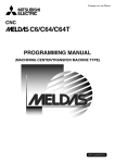
1. System Configuration
1.1 System Basic Configuration Drawing
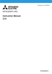
1. System Configuration
1.1 System Basic Configuration Drawing
HMI GOT
GT Works3
Memory card
or USB
CNC UNIT
EMG
GX Works2
GX Developer
CPU
Q 170D BAT
C
BATTER
Y
MANUAL PLG
M IT S U B IS H I
LIT H IU M
B A TTE RY
NC Configurator2
NC Analyzer
Battery
EXT. UNIT
QXxxxx
QXxxxx
QXxxxx
CNC Drive System
I-1
SKIP
1. System Configuration
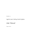
1.2 General Connection Diagram
1.2 General Connection Diagram
Display module
GOT2000 Series
GOT1000 Se
Series
Specifications including unit names , cable
names, and maximum lengths of cables are
subject to change without notice. Always
confirm these details before placing an order.
H200 cable (panel internal wiring)
(Note) Ethernet Module
GT15-J71E1-100 is
required for GT15
24VDC or
100 240VAC
CPU Module
/Network Module
H500 Cable
(Max:0.5m)
H500
Cable
Dual
Signal
Module
I/O
Module
#1
RIO2
RIO1
PLCIO
NCIO
Dual
Signal
Module
Dual
Signal
Module
RIO2
CPU/
Network
Module
#2
PLCIO
NCIO
ACIN/DCIN
CPU/
Network
Module
#1
RIO1
Q312DB
CN1
Source Power
AC/DC
CNCCPU
Module
Q173NCCPU
EXT I/F
RIO
Basic
Base
EMG DISPLAY
I/F
BAT
MPG
Power
Unit
PLC
CPU
Module
MELSEC-Q I/O Module
/Intelligent Module
Dual Signal Module
RIO2
FG
PLCIO
NCIO
24VDC
H100 Cable G302 cable (panel external wiring)
(Max:30m)
(Max:20m)
RIO1
EMG
I/O
Module
#2
H500
Cable
Cable for ternimal block
F A-CBL
FMV-M
(Max:5m)
Battery
Q6BAT
Battery Unit
Q173NCBATC
MPG#1
I/O I/O I/O I/O
Mod- Mod- Mod- Module ule ule ule
#3 #4
#5 #6
Machine I/O
/Operation panel
CNC I/O
T erminal block type : F A-LTB40P
DCIN
H400 Cable
(Max:20m)
24VDC (Not used)
PLC I/O
T erminal block type : F A-LTB40P
DCIN
Manual Pulse Generator
UFO-01-2Z9 (5VDC)
Cable
G396 (max10m, for wiring
inside the panel)
G395 (max10m, for wiring
outside the panel)
G380 (max20m, for wiring
outside the panel)
24VDC (Not used)
SKIP signals . 4 points (24VDC)
H310 Cable
(Max:15m)
H010 Cable
(Max:5m)
Signal splitter
FCU7-HN387
SKIP
SW
TU I/F
MPG TERMINALDCIN
Drive Units
24VDC (Not used)
(12VDC) (Note 1)
H300
Cable
(Max:20m)
Notes
SKIP
signals.
4 points
(24VDC)
MPG#2
MPG#3
Manual
Pulse
Generator
UFO-01-2Z9 (5VDC)
: Prepared by user
: Used with connector.
Cannot be used with cable H300 at the same time
Cable
G020(5VDC,1ch,Max:15m)
G021(5VDC,2ch,Max:15m)
G022(5VDC,3ch,Max:15m)
F020(12VDC,1ch,Max:45m)
F021(12VDC,2ch,Max:45m)
F022(12VDC,3ch,Max:45m)
(Note 1) HD60C (12VDC) requires another power source12VDC.
I-2
HD60C (12VDC) (Note 1)
1. System Configuration
1.3 Component Modules
1.3 Component Modules
1.3.1 CNC Control Unit
(1) Basic base
Model name
Remarks
Q35DB
5 slots
Q38DB
8 slots
Q312DB
12 slots
Reference
QCPU User’s Manual
(Hardware Design,
Maintenance and Inspection)
(SH(NA)-080483ENG)
(2) Power supply
Model name
Remarks
Q61P
Input power supply : 100 to 240VAC
Output power supply : 5VDC
Output current:6A
Q63P
Input power supply: 24VDC
Output power supply: 5VDC
Output current: 6A
Q64PN
Input power supply : 100 to 240VAC
Output power supply : 5VDC
Output current : 8.5A
Q64P
Input power supply: 100 to 120VAC/
200 to 240VAC
Output power supply: 5VDC
Output current: 8.5A
(Note) Out of production
I-3
Reference
QCPU User’s Manual
(Hardware Design,
Maintenance and Inspection)
(SH(NA)-080483ENG)
1. System Configuration
1.3 Component Modules
(3) PLC CPU
Model name
Remarks
Q03UDCPU
Program capacity: 30k steps
Q04UDHCPU
Program capacity: 40k steps
Q06UDHCPU
Program capacity: 60k steps
Q13UDHCPU
Program capacity:130k steps
Q26UDHCPU
Program capacity:260k steps
Reference
Q03UDECPU
Ethernet built-in type, Program capacity: 30k steps
Q04UDEHCPU
Ethernet built-in type, Program capacity: 40k steps
Q06UDEHCPU
Ethernet built-in type, Program capacity: 60k steps
Q10UDEHCPU
Ethernet built-in type, Program capacity: 100k steps
Q13UDEHCPU
Ethernet built-in type, Program capacity: 130k steps
Q26UDEHCPU
Ethernet built-in type, Program capacity: 260k steps
Q03UDVCPU
High-speed type, Program capacity: 30k steps
(Note)
Q04UDVCPU
High-speed type, Program capacity: 40k steps
(Note)
Q06UDVCPU
High-speed type, Program capacity: 60k steps
(Note)
Q13UDVCPU
High-speed type, Program capacity: 130k steps
(Note)
Q26UDVCPU
High-speed type, Program capacity: 260k steps
(Note)
(Note)
QCPU User’s Manual
(Hardware Design,
Maintenance and Inspection)
(SH(NA)-080483ENG)
The High-Speed Universal model is compatible with the safety observation function, but not yet
certified under the European safety standards “EN ISO 13849-1 Cat3 PL d” or “EN62061/SIL CL2”
by TUV.
(4) CNC CPU module
Model name
Remarks
Q173NCCPU-S01
CNC CPU module
Battery kit
One each of following accessories are provided:
Battery holder unit+Connection cable (0.5m) Q173NCBATC(Q170DBATC), Battery
Q6BAT
(5) Battery holder unit
Model name
Q173NCBATC
Remarks
Battery holder unit
I-4
1. System Configuration
1.3 Component Modules
(6) Input module
(a) AC
Model name
Remarks
QX10
16 points, 100 to 120VAC
8mA(100VAC, 60Hz)/7mA(100VAC, 50Hz)
Response time: 20ms
16 points/common, 18-point terminal block
QX28
8 points, 100 to 240VAC
17mA(200VAC, 60Hz)
/14mA(200VAC, 50Hz)/8mA(100VAC, 60Hz)/
7mA(100VAC, 50Hz)
Response time: 20ms
8 points/common, 18-point terminal block
Reference
I/O module Type Building
Block User’s Manual
(SH(NA)-080042)
(b) DC (positive common type)
Model name
Remarks
QX40
16 points, 24VDC, 4mA,
Response time: 1/5/10/20/70ms
16 points/common, Positive common type
18-point terminal block
QX40-S1
16 points, 24VDC, 6mA,
Response time: 0.1/0.2/0.4/0.6/1ms
16 points/common, Positive common type
18-point terminal block
QX41
32 points, 24VDC, 4mA,
Response time: 1/5/10/20/70ms
32 points/common, Positive common type
40-pin connector
QX41-S1
32 points, 24VDC, 4mA,
Response time: 0.1/0.2/0.4/0.6/1ms
32 points/common, Positive common type
40-pin connector
QX42
64 points, 24VDC, 4mA,
Response time: 1/5/10/20/70ms
32 points/common, Positive common type
40-pin connector
QX42-S1
64 points, 24VDC, 4mA,
Response time: 0.1/0.2/0.4/0.6/1ms
32 points/common, Positive common type
40-pin connector
I-5
Reference
I/O module Type Building
Block User’s Manual
(SH(NA)-080042)
1. System Configuration
1.3 Component Modules
(c) DC sensor
Model name
Remarks
QX70
16 points, 5/12VDC, 1.2mA(5VDC)/3.3mA(12VDC)
Response time: 1/5/10/20/70ms
16 points/common, Positive/negative common type
18-point terminal block
QX71
32 points, 5/12VDC, 1.2mA(5VDC)/3.3mA(12VDC)
Response time: 1/5/10/20/70ms
32 points/common, Positive/negative common type
40-pin connector
QX72
64 points, 5/12VDC, 1.2mA(5VDC)/3.3mA(12VDC)
Response time: 1/5/10/20/70ms
32 points/common, Positive/negative common type
40-pin connector
Reference
I/O module Type Building
Block User’s Manual
(SH(NA)-080042)
(d) DC (negative common type)
Model name
Remarks
QX80
16 points, 24VDC, 4mA
Response time: 1/5/10/20/70ms
16 points/common, Negative common type
18-point terminal block
QX81
32 points, 24VDC, 4mA
Response time: 1/5/10/20/70ms
32 points/common, Negative common type
37-pin D sub-connector
QX82
64 points, 24VDC, 4mA
Response time: 1/5/10/20/70ms
32 points/common, Negative common type
40-pin connector
QX82-S1
64 points, 24VDC 4mA
Response time: 0.2/0.3/0.5/0.7/1.3ms
32 points/common, Negative common type
40-pin connector
I-6
Reference
I/O module Type Building
Block User’s Manual
(SH(NA)-080042)
1. System Configuration
1.3 Component Modules
(7) Analog input module
(a) Voltage input module
Model name
Q68ADV
Remarks
8 channels,
Input: -10 to 10VDC
Output (resolution): 0 to 4000; -4000 to 4000;
0 to 12000; -12000 to 12000; 0 to 16000;
-16000 to 16000
Conversion speed: 80µs/channel
18-point terminal block
Reference
Analog-Digital Converter
Module User's Manual
(SH(NA)-080055)
(b) Current input module
Model name
Remarks
Reference
Q62AD-DGH
2 channels,
Input: 4 to 20mADC
Output (resolution): 0 to 32000; 0 to 64000
Conversion speed: 10ms/2channels
18-point terminal block, Channels are isolated,
Power supply for 2-wire transmitter
Channel Isolated High
Resolution Analog-Digital
Converter Module/Channel
Isolated High Resolution
Analog-Digital Converter
Module (With Signal
Conditioning Function) User’s
Manual
(SH(NA)-080277)
Q68ADI
8 channels,
Input: 0 to 20mADC
Output (resolution): 0 to 4000; -4000 to 4000;
0 to 12000; -12000 to 12000; 0 to 16000;
-16000 to 16000
Conversion speed: 80µs/channel
18-point terminal block
Analog-Digital Converter
Module User's Manual
(SH(NA)-080055)
(c) Voltage/current input module
Model name
Q64AD
Q64AD-GH
Remarks
Reference
4 channels,
Input: -10 to 10VDC, 0 to 20mADC
Output (resolution): 0 to 4000; -4000 to 4000;
0 to 12000; -12000 to 12000; 0 to 16000;
-16000 to 16000
Conversion speed: 80µs/channel
18-point terminal block
Analog-Digital Converter
Module User's Manual
(SH(NA)-080055)
4 channels,
Input: -10 to 10VDC, 0 to 20mADC
Output (resolution): 0 to 32000; -32000 to 32000;
0 to 64000; -64000 to 64000
Conversion speed: 10ms/4channels
18-point terminal block, Channels are isolated
Channel Isolated High
Resolution Analog-Digital
Converter Module/Channel
Isolated High Resolution
Analog-Digital Converter
Module (With Signal
Conditioning Function) User’s
Manual
(SH(NA)-080277)
I-7
1. System Configuration
1.3 Component Modules
(8) Output module
(a) Relay
Model name
Remarks
QY10
16 points, 24VDC/240VAC, 2A/point, 8A/common
Response time: 12ms 16 points/common
18-point terminal block
QY18A
8 points, 24VDC/240VAC, 2A/point
Response time: 12ms
18-point terminal block, All relays isolated
Reference
I/O module Type Building
Block User’s Manual
(SH(NA)-080042)
(b) Triac
Model name
Remarks
16 points, 100 to 240VAC, Minimum load voltage
Current: 24VAC, 100mA/100/240VAC, 25mA,
OFF-time leakage current: 1.5mA(120VAC)/
3mA(240VAC)
Response time: 1ms+0.5 cycle
16 points/common, 18-point terminal block
Surge killer provided
QY22
Reference
I/O module Type Building
Block User’s Manual
(SH(NA)-080042)
(c) Transistor (sink type)
Model name
Remarks
QY40P
16 points, 12 to 24VDC
OFF-time leakage current: 0.1mA
Response time: 1ms, 16 points/common, Sink type
18-point terminal block, Thermal protection
provided, Short circuit protection provided
Surge killer provided
QY41P
32 points, 12 to 24VDC
OFF-time leakage current: 0,1mA
Response time: 1ms, 32 points/common, Sink type
40-pin connector, Thermal protection provided
Short circuit protection provided
Surge killer provided
QY42P
64 points, 12 to 24VDC
OFF-time leakage current: 0.1mA
Response time: 1ms, 32 points/common, Sink type
40-pin connector, Thermal protection provided
Short circuit protection provided
Surge killer provided
QY50
16 points, 12 to 24VDC
OFF-time leakage current: 0.1mA
Response time: 1ms, 16 points/common, Sink type
18-point terminal block, Surge killer provided
Fuse provided
I-8
Reference
I/O module Type Building
Block User’s Manual
(SH(NA)-080042)
1. System Configuration
1.3 Component Modules
(d) Transistor (independent)
Model name
Remarks
8 points, 5 to 24VDC
OFF-time leakage current: 0.1mA
Response time: 10ms, Sink/source type
18-point terminal block, Surge killer provided
All points isolated
QY68A
Reference
I/O module Type Building
Block User’s Manual
(SH(NA)-080042)
(e) TTL CMOS
Model name
Remarks
QY70
16 points, 5 to 12VDC, Response time: 0.5ms
16 points/common, Sink type
18-point terminal block, Fuse provided
QY71
32 points, 5 to 12VDC, Response time: 0.5ms
32 points/common, Sink type
40-pin connector, Fuse provided
Reference
I/O module Type Building
Block User’s Manual
(SH(NA)-080042)
(f) Transistor (source type)
Model name
Remarks
QY80
16 points, 12 to 24VDC
OFF-time leakage current: 0.1mA
Response time: 1ms, 16 points/common
Source type, 18-point terminal block
Surge killer provided, Fuse provided
QY81P
32 points, 12 to 24VDC
OFF-time leakage current: 0.1mA
Response time: 1ms, 32 points/common
Source type, 37-pin D sub-connector, Thermal
protection provided, Short circuit protection
provided, Surge killer provided
QY82P
64 points, 12 to 24VDC
OFF-time leakage current: 0.1mA
Response time: 1ms, 32 points/common, Source
type
40-pin connector, Thermal protection provided
Short circuit protection provided
Surge killer provided
I-9
Reference
I/O module Type Building
Block User’s Manual
(SH(NA)-080042)
1. System Configuration
1.3 Component Modules
(9) Analog output module
(a) Voltage output module
Model name
Q68DAVN
Remarks
8 channels
Input (resolution): 0 to 4000; -4000 to 4000;
0 to 12000; -12000 to 12000; -16000 to 16000
Output: -10 to 10VDC
Conversion speed: 80µs/channel
18-point terminal block, Transformer insulation
between power supply and output modules
Reference
Digital-Analog Converter
Module User's Manual
(SH(NA)-080054)
(b) Current input module
Model name
Q68DAIN
Remarks
8 channels
Input (resolution): 0 to 4000; -4000 to 4000;
0 to 12000; -12000 to 12000
Output: 0 to 20mADC
Conversion speed: 80µs/channel
18-point terminal block, Transformer insulation
between power supply and output modules
Reference
Digital-Analog Converter
Module User's Manual
(SH(NA)-080054)
(c) Voltage/current output module
Model name
Remarks
Reference
Q62DAN
2 channels
Input (resolution): 0 to 4000; -4000 to 4000;
0 to 12000; -12000 to 12000; -16000 to 16000
Output: -10 to 10VDC, 0 to 20mADC
Conversion speed: 80µs/channel
18-point terminal block, Transformer insulation
between power supply and output modules
Digital-Analog Converter
Module User's Manual
(SH(NA)-080054)
Q62DA-FG
2 channels
Input (resolution): 0 to 12000; -12000 to 12000; 16000 to 16000
Output: -12 to 12VDC, 0 to 22mADC
Conversion speed: 10ms/2channels
18-point terminal block, Channels are isolated
Channel Isolated DigitalAnalog Converter Module
User's Manual
(SH(NA)-080281)
Q64DAN
4 channels
Input (resolution): 0 to 4000; -4000 to 4000;
0 to 12000; -12000 to 12000; -16000 to 16000
Output: -10 to 10VDC, 0 to 20mADC
Conversion speed: 80µs/channel
18-point terminal block, Transformer insulation
between power supply and output modules
Digital-Analog Converter
Module User's Manual
(SH(NA)-080054)
(10) Interrupt input module
Model name
QI60
Remarks
16 points, 24VDC 4mA
Response time: 0.1/0.2/0.4/0.6/1ms
16 points/common, 18-point terminal block
I - 10
Reference
I/O module Type Building
Block User’s Manual
(SH(NA)-080042)
1. System Configuration
1.3 Component Modules
(11) Temperature input module
(a) RTD
Model name
Q64RD
Q64RD-G
Remarks
4 channels
Platinum RTD (Pt100(JIS C1604-1997, IEC 751
1983), JPt100(JISC1604-1981))
Conversion speed: 40ms/channel
18-point terminal block
4 channels
Platinum RTD (Pt100(JIS C1604-1997, IEC 751
1983), JPt100(JISC1604-1981), Ni100Ω(DIN43760
1987))
Conversion speed: 40ms/channel
18-point terminal block, Channels are isolated
Reference
RTD Input Module Channel
Isolated RTD Input Module
User's Manual
(SH(NA)-080142)
(b) Thermocouple
Model name
Remarks
Q64TD
4 channels, Thermocouple (JIS C1602-1995)
Conversion speed: 40ms/channel
18-point terminal block
Q64TDV-GH
4 channels, Thermocouple (JIS C1602-1995)
Micro voltage input range: -100mV to 100mV
Conversion speed: (sampling period 3)/channel
18-point terminal block
Q64TCTT
4 channels, Thermocouple (K, J, T, B, S, E, R, N, U,
L, PLII, W5Re/W26Re)
Without heater disconnection detection
Sampling period: 0.5s/4channels
18-point terminal block
Q64TCTTBW
4 channels, Thermocouple (K, J, T, B, S, E, R, N, U,
L, PLII, W5Re/W26Re)
With heater disconnection detection
Sampling period: 0.5s/4channels
2 units of 18-point terminal block
Reference
Thermocouple Input Module
Channel Isolated
Thermocouple/Micro Voltage
Input Module User's Manual
(SH(NA)-080141)
Temperature Control Module
User's Manual
(SH(NA)-080121)
(c) Platinum RTD
Model name
Q64TCRT
Q64TCRTBW
Remarks
4 channels, Platinum RTD (Pt100, JPt100)
Without heater disconnection detection
Sampling period: 0.5s/4channels
18-point terminal block
4 channels, Platinum RTD (Pt100, JPt100)
With heater disconnection detection
Sampling period: 0.5s/4channels
2 units of 18-point terminal block
Reference
Temperature Control Module
User's Manual
(SH(NA)-080121)
(d) Loop controller
Model name
Q62HLC
Remarks
Loop control module
Thermocouple input 2ch, 5 modes of PID control
Output: 4 to 20mA
I - 11
Reference
Loop Control Module User's
Manual
(SH(NA)-080573ENG)
1. System Configuration
1.3 Component Modules
(12) Channel isolated pulse input module
Model name
QD60P8-G
Remarks
8 channels 30kpps/10kpps/1kpps/100pps/50pps/
10pps/1pps/0.1pps
Count input signal: 5/12 to 24VDC
Reference
Channel Isolated Pulse Input
Module User's Manual
(SH(NA)-080313E)
(13) High-speed counter module
Model name
Remarks
QD62
2 channels, 200/100/10kpps
Count input signal: 5/12/24VDC
External input: 5/12/24VDC
Coincidence output: transistor (sink type)
12/24VDC, 0.5A/point, 2A/common
40-pin connector
QD62D
2 channels, 500/200/100/10kpps
Count input signal: EIA Standard RS-422-A
(differential line driver level)
External input: 5/12/24VDC
Coincidence output: transistor (sink type)
12/24VDC, 0.5A/point, 2A/common
40-pin connector
QD62E
2 channels, 200/100/10kpps
Count input signal: 5/12/24VDC
External input: 5/12/24VDC
Coincidence output: transistor (source type)
12/24VDC, 0.1A/point, 0.4A/common
40-pin connector
Reference
High-Speed Counter Module
User's Manual
(SH(NA)-080036)
(14)Ethernet
Model name
Remarks
QJ71E71-100
10BASE-T/100BASE-TX
QJ71E71-B2
10BASE2
QJ71E71-B5
10BASE5
Reference
Q Corresponding MELSEC
Communication Protocol
Reference Manual
(SH(NA)-080008)
(15)Serial communication
Model name
Remarks
QJ71C24N
RS-232 1 channel, RS-422/485 1 channel
Transmission rate: 230.4kbps (Total)
QJ71C24N-R2
RS-232 2 channels
Transmission rate: 230.4kbps (Total)
QJ71C24N-R4
RS-422/485 2 channels
Transmission rate: 230.4kbps (Total)
I - 12
Reference
Q Corresponding Serial
Communication Module
User's Manual (Basic)
(SH(NA)-080006)
1. System Configuration
1.3 Component Modules
(16) MES interface module
Model name
QJ71MES96
Remarks
Reference
10BASE-T/100BASE-TX 1 channel
(Note) MX MESInterface and CF card are separately
required.
MES Interface Module User's
Manual
(SH(NA)-080644ENG)
(17) MELSECNET/H
(a) SI/QSI optical interface
Model name
Remarks
QJ71LP21-25
SI/QSI/H-PCF/Broad-band H-PCF optical cable,
Double loop
PLC to PLC network (control/normal station)/
Remote I/O net (remote master station)
QJ71LP21S-25
SI/QSI/H-PCF/Broad-band H-PCF optical cable,
Double loop
PLC to PLC network (control/normal station)/
Remote I/O net (remote master station)
With external supply power
QJ72LP25-25
SI/QSI/H-PCF/Broad-band H-PCF optical cable,
Double loop
Remote I/O net (remote I/O station)
Reference
Q Corresponding
MELSECNET/H Network
System Reference
Manual(PLC to PLC network)
(SH(NA)-080049)
Q Corresponding
MELSECNET/H Network
System Reference
Manual(Remote I/O network)
(SH(NA)-080124)
For QnA/Q4AR
MELSECNET/10 Network
System Reference Manual
(IB(NA)-66690)
(b) GI optical interface
Model name
QJ71LP21G
QJ72LP25G
Remarks
Reference
GI optical cable, Double loop
PLC to PLC network (control/normal station)/
Remote I/O net (remote master station)
Q Corresponding
MELSECNET/H Network
System Reference
Manual(PLC to PLC network)
(SH(NA)-080049)
Q Corresponding
MELSECNET/H Network
System Reference
Manual(Remote I/O network)
(SH(NA)-080124)
For QnA/Q4AR
MELSECNET/10 Network
System Reference Manual
(IB(NA)-66690)
GI optical cable, Double loop
Remote I/O net (remote I/O station)
Q corresponding
MELSECNET/H Network
System Reference
Manual(Remote I/O network)
(SH(NA)-080124)
I - 13
1. System Configuration
1.3 Component Modules
(c) Coaxial interface
Model name
QJ71BR11
QJ72BR15
Remarks
Reference
3C-2V/5C-2V coaxial cable, Single bus
PLC to PLC network (control/normal station)/
Remote I/O net (remote master station)
Q Corresponding
MELSECNET/H Network
System Reference
Manual(PLC to PLC network)
(SH(NA)-080049)
Q Corresponding
MELSECNET/H Network
System Reference
Manual(Remote I/O network)
(SH(NA)-080124)
For QnA/Q4AR
MELSECNET/10 Network
System Reference Manual
(IB(NA)-66690)
3C-2V/5C-2V coaxial cable, Single bus
Remote I/O net (remote I/O station)
Q corresponding
MELSECNET/H Network
System Reference
Manual(Remote I/O network)
(SH(NA)-080124)
(18) CC-Link
Model name
QJ61BT11N
Remarks
For master/local station, For QCPU
Compatible with CC-Link Ver.2
Reference
CC-Link System Master/Local
Module User's Manual
SH(NA)-080394E
(19) CC-Link IE controller network
Model name
Remarks
QJ71GP21-SX
CC-Link IE Optical double loop interface module
(1000BASE-SX) Control/normal station
QJ71GP21S-SX
CC-Link IE Optical double loop interface module
(1000BASE-SX) Control/normal station
With external power supply
I - 14
Reference
CC-Link IE Controller Network
Reference Manual
(SH(NA)-080668)
1. System Configuration
1.3 Component Modules
(20) FL-net (OPCN-2)
(a) Ver.2.00
Model name
Remarks
QJ71FL71-T-F01
10BASE-T/100BASE-TX
QJ71FL71-B2-F01
10BASE2
QJ71FL71-B5-F01
10BASE5
Reference
FL-net(OPCN-2) Interface
Module User’s Manual
(SH(NA)-080350E)
(b) Ver.1.00
Model name
Remarks
QJ71FL71-T
10BASE-T
QJ71FL71-B2
10BASE2
QJ71FL71-B5
10BASE5
Reference
FL-net(OPCN-2) Interface
Module User’s Manual
(SH(NA)-080350E)
(21) AS-i
Model name
QJ71AS92
Remarks
Reference
AS-i Master Module User’s
Manual (Hardware)
(IB(NA)-0800122E)
Master station
(22) Extension base
Model name
Remarks
Q63B
3 slots; for mounting Q series modules
including power supply module
Q65B
5 slots; for mounting Q series modules
including power supply module
Q68B
8 slots; for mounting Q series modules
including power supply module
Q612B
12 slots; for mounting Q series modules
including power supply module
Q52B
2 slots; for mounting Q series modules
excluding power supply module
Q55B
5 slots; for mounting Q series modules
excluding power supply module
I - 15
Reference
QCPU User’s Manual
(Hardware Design,
Maintenance and Inspection)
(SH(NA)-080483ENG)
1. System Configuration
1.3 Component Modules
(23) Spring clamp terminal block
Model name
Q6TE-18S
Remarks
Reference
For 16 points I/O modules, 0.3 to 1.5mm2 (AWG22
to 16)
Spring Clamp Terminal Block
Model Q6TE-18S User’s
Manual (IB(NA)-0800204E)
Remarks
Reference
(24) Terminal block adapter
Model name
Q6TA32
For 32 points I/O modules, 0.5mm2 (AWG20)
Q6TA32-TOL
Q6TA32 exclusive tool
Insulation Displacement
Connector for MELSEC-Q
Series 32-Point I/O Module
User's Manual
(IB(NA)-0800228E)
(25) Connector/terminal block converter module
Model name
Remarks
A6TBX36-E
For negative common type input modules
(standard type)
A6TBX54-E
For negative common type input modules
(2-wire type)
A6TBX70
For positive common type input modules
(3-wire type)
A6TBX70-E
For negative common type input modules
(3-wire type)
A6TBY36-E
For source type output modules (standard type)
A6TBY54-E
For source type output modules (2-wire type)
A6TBXY36
For positive common type input modules and sink
type output modules (standard type)
A6TBXY54
For positive common type input modules and sink
type output modules (2-wire type)
I - 16
Reference
I/O module Type Building
Block User’s Manual
(SH(NA)-080042)
1. System Configuration
1.3 Component Modules
(26) Cable
(a) Cables for CNC CPU
Cable type
F020
F021
F022
G020
G021
G022
G302
G303
G380
Max.
length
Manual pulse generator: 45m
1ch
Manual pulse generator: 45m
2ch
Manual pulse generator: 45m
3ch
Manual pulse generator: 15m
1ch
Manual pulse generator: 15m
2ch
Manual pulse generator: 15m
3ch
Display module
20m
communication
(STP cross)
Display module
20m
communication
(STP straight)
Optical communication 20m
cable
Application
Standard cable length
(m)
0.5, 1, 2, 3, 5, 7, 10, 15, 20
0.5, 1, 2, 3, 5, 7, 10, 15, 20
0.5, 1, 2, 3, 5, 7, 10, 15
0.5, 1, 2, 3, 5, 7, 10, 15
1, 2, 3, 5, 10, 15, 20
For panel external wiring
1, 2, 3, 5, 10, 15, 20
For panel external wiring,
when using a HUB.
5, 10, 12, 15, 20
For wiring between drive units
(outside panel)
For optical communication
repeater unit
For wiring between drive units
(outside panel)
For wiring between NC-drive units
For wiring between drive units
(inside panel)
10m
1, 2, 3, 5, 7, 10
G396
Optical communication
cable
Signal splitter
connection
Emergency stop
Display module
communication
(UTP cross)
SKIP/manual pulse
generator input
SKIP connection
Manual pulse generator:
1ch for 5V
Dual-signal module
communication
Connection cable
between
I/O extension connector
unit (FCU7-HN831) and
external Input/output
unit (GT15-DIOR)
10m
0.3, 0.5, 1, 2, 3, 5
5m
0.5, 1, 2, 3, 5
30m
20m
0.5, 1, 2, 3, 5, 7, 10, 15, 20
1, 2, 3, 5, 10, 15, 20
20m
0.5, 1, 2, 3, 5, 7, 10, 15, 20
15m
20m
0.5, 1, 2, 3, 5, 7, 10, 15
0.5, 1, 2, 3, 5, 7, 10, 15, 20
0.5m
0.1, 0.2, 0.3, 0.5
1m
0.5, 0.75, 1
H300
H310
H400
H500
H810
5V power supply type can be
used.
For Signal splitter
0.5, 1, 2, 3, 5, 7, 10, 15
Optical communication
cable
H100
H200
12V power supply type can be
used.
For Signal splitter
0.5, 1, 2, 3, 5, 7, 10, 15, 20
G395
H010
Remarks
For panel internal wiring.
For Signal splitter
(Note) The Standard cable length column shows the lengths of the cable available from MITSUBISHI.
I - 17
1. System Configuration
1.3 Component Modules
(b) Cable for connector and terminal block changeover unit
Model name
Remarks
AC05TB
For A6TBXY36/A6TBXY54/A6TBX70
(positive common/sink type modules), 0.5m
AC10TB
For A6TBXY36/A6TBXY54/A6TBX70
(positive common/sink type modules), 1m
AC20TB
For A6TBXY36/A6TBXY54/A6TBX70
(positive common/sink type modules), 2m
AC30TB
For A6TBXY36/A6TBXY54/A6TBX70
(positive common/sink type modules), 3m
AC50TB
For A6TBXY36/A6TBXY54/A6TBX70
(positive common/sink type modules), 5m
AC80TB
For A6TBXY36/A6TBXY54/A6TBX70
(positive common/sink type modules), 8m
*Common current not exceeding 0.5A
AC100TB
For A6TBXY36/A6TBXY54/A6TBX70
(positive common/sink type modules), 10m
*Common current not exceeding 0.5A
AC05TB-E
For A6TBX36-E/A6TBY36-E/A6TBX54-E
/A6TBY54-E/A6TBX70-E
(negative common, source type modules), 0.5m
AC10TB-E
For A6TBX36-E/A6TBY36-E/A6TBX54-E
/A6TBY54-E/A6TBX70-E
(negative common, source type modules), 1m
AC20TB-E
For A6TBX36-E/A6TBY36-E/A6TBX54-E
/A6TBY54-E/A6TBX70-E
(negative common, source type modules), 2m
AC30TB-E
For A6TBX36-E/A6TBY36-E/A6TBX54-E/
A6TBY54-E/A6TBX70-E (negative common,
AC30TB-E source type modules), 3m
AC50TB-E
For A6TBX36-E/A6TBY36-E/A6TBX54-E
/A6TBY54-E/A6TBX70-E
(negative common, source type modules), 5m
I - 18
Reference
I/O module Type Building
Block User’s Manual
(SH(NA)-080042)
1. System Configuration
1.3 Component Modules
(c) Cable for drive unit
Cable type
Application
Max.
length
Standard cable length
(m)
Remarks
CNP2E-1-□M
Motor side PLG cable
Spindle side accuracy detector
TS5690 cable
CNV22J-K1P0.3M
For HF-KP (Servo) Motor side detector relay cable (motor side)
0.3m
Compatible with only IP65
0.3
(load side angle)
CNV22J-K2P0.3M
For HF-KP (Servo) Motor side detector relay cable (motor side)
0.3m
Compatible with only IP65
0.3
(reverse load side angle)
CNV2E-8P-□M
For HF/HF-H, HF-KP (Tool spindle) Motor side detector cable (for
30m
A48/A51/A74N(/A74)) /
For HF-KP (Servo) Motor side detector relay cable (Drive unit side)
2, 3, 4, 5, 7, 10, 15, 20, 25, 30
CNV2E-9P-□M
For HF/HF-H, HF-KP (Tool spindle) Motor side detector cable (for 30m
A48/A51/A74N(/A74))
2, 3, 4, 5, 7, 10, 15, 20, 25, 30
CNV2E-D-□M
MDS-B-SD unit cable
30m
2, 3, 4, 5, 7, 10, 15, 20, 25, 30
CNV2E-HP-□M
MDS-B-HR unit cable
30m
2,3,4,5,7,10,15,20,25,30
CNV2E-K1P□M
For HF-KP (Servo) Motor side detector cable
10m
Compatible with only IP65
2, 3, 5, 7, 10
(load side angle)
CNV2E-K2P□M
For HF-KP (Servo) Motor side detector cable
10m
Compatible with only IP65
2, 3, 5, 7, 10
(reverse load side angle)
DG21-□M
Battery cable
0.3, 0.5, 1, 5
(For drive unit (except MDS-DJ Series) battery unit)
0.3, 0.5, 1, 5
(For servo drive unit - servo drive unit (except MDS-DJ Series))
(Note) This cable is required to supply the
power from the battery unit to multiple
drive units.
0.3, 0.5, 1, 5
(For servo drive unit (except MDS-DJ Series) -battery box)
(Note) The battery box side is connected
using a bare conductor or a terminal bar.
DG22-□M
DG23-□M
Battery cable
Battery cable
30m
5m
5m
5m
2, 3, 4, 5, 7, 10, 15, 20, 25, 30
DG24-□M
5V spply/DO output cable
5m
0.3, 0.5, 1, 5
(For servo drive unit (except MDS-DJ Series) -battery box)
(Note) The battery box side is connected
using a bare conductor or a terminal bar.
MRBKS1CBL□MA1-H
<200V Series>
Brake cable for HF-KP
10m
2, 3, 5, 7, 10
(load side angle)
MRBKS1CBL□MA2-H
<200V Series>
Brake cable for HF-KP
10m
2, 3, 5, 7, 10
(reverse load side angle)
MRPWS1CBL□MA1-H
<200V Series>
Power cable for HF-KP
10m
2, 3, 5, 7, 10
(load side angle)
MRPWS1CBL□MA2-H
<200V Series>
Power cable for HF-KP
10m
2, 3, 5, 7, 10
(reverse load side angle)
(Note) It can not be used with HF-KP13.
SH21
Power supply communication cable
Power backup unit communication cable
Cable for Auxiliary axis/Servo
drive unit
30m
0.35, 0.5, 1, 2, 3, 5, 10, 15,
20, 30
(Note) The Standard cable length column shows the lengths of the cable available from MITSUBISHI.
I - 19
1. System Configuration
1.3 Component Modules
(27) Relay terminal unit
(a) Unit
Model name
A6TE2-16SRN
Remarks
Reference
40 pin connector
For 24VDC Transistor output unit (sink type
module)
Relay Terminal Module User's
Manual (Hardware)
A6TE2-16SRN
(IB(NA)-66833)
Remarks
Reference
(b) Cable
Model name
AC06TE
For A6TE2-16SRN 0.6m
AC10TE
For A6TE2-16SRN 1m
AC30TE
For A6TE2-16SRN 3m
AC50TE
For A6TE2-16SRN 5m
AC100TE
For A6TE2-16SRN 10m
Relay Terminal Module User's
Manual (Hardware)
A6TE2-16SRN
(IBNA)-66833)
(28) Extension cable
Model name
Remarks
QC05B
0.45m cable
QC06B
0.6m cable
QC12B
1.2m cable
QC30B
3m cable
QC50B
5m cable
QC100B
10m cable
Reference
QCPU User’s Manual
(Hardware Design,
Maintenance and Inspection)
(SH(NA)-080483ENG)
(29) Connector
Model name
Remarks
A6CON1
Soldering type 32 point-connector
(40-pin connector)
A6CON2
Crimp-contact type 32 point-connector
(40-pin connector)
A6CON3
Flat cable pressure displacement type 32-point
connector (40-pin connector)
A6CON4
Soldering type 32 point-connector
(40-pin connector; two-way cable can be mounted)
A6CON1E
Soldering type 32 point-connector
(37-pin D sub-connector)
A6CON2E
Crimp-contact type 32 point-connector
(37-pin D sub-connector)
A6CON3E
Flat cable pressure displacement type 32-point
connector (37-pin D sub-connector)
I - 20
Reference
I/O module Type Building
Block User’s Manual
(SH(NA)-080042)
1. System Configuration
1.3 Component Modules
(30) Memory card
Model name
Q2MEM-2MBS
Remarks
Small SRAM memory card 2MB
Reference
QCPU user manual (hard ware
designing/maintenance)(SH080472)
(31) CC-Link Remote I/O unit
(a) Thread terminal block type
Model name
AJ65SBTB1-32D
AJ65SBTB1-32TE1
Remarks
Input 32 points: 24VDC (positive/negative common
shared type),
1- wire, terminal block type, response time: 1.5 ms
Reference
CC-Link System Compact Type
Remote I/O Module User's
Output 32 points: 12/24VDC (0.5A), transistor output Manual(SH-4007)
(source type), 1-wire, terminal block type
(b) Waterproof connector type
Model name
AJ65FBTA4-16DE
AJ65FBTA2-16TE
Remarks
Reference
Input 16 points: 24VDC (negative common ), 4-wire,
CC-Link System Compact Type
super-slim waterproof type, response time: 1.5 ms
Remote I/O Module User's
Output 16 points: 12/24VDC (1.0A), transistor output Manual(SH-4007)
(source type), 2-wire, super-slim waterproof type
I - 21
1. System Configuration
1.3 Component Modules
1.3.2 GOT
1.3.2.1 GT27
(1) GOT
(a) GT2712
Model name
GT2712-STBA
GT2712-STBD
Remarks
12.1-type SVGA[800 × 600 dots] TFT color liquid
crystal display, 65536 colors
<Multimedia and video/RGB and multi-touch
supported>
100-240VAC, user memory, memory for
storage(ROM):57MB, operation memory
(RAM):128MB
- Requiring GT Designer3 Version1(GOT2000)
1.117X or later.
12.1-type SVGA[800 × 600 dots] TFT color liquid
crystal display, 65536 colors
<Multimedia and video/RGB and multi-touch
supported>
24VDC, user memory, storage memory
(ROM):57MB, operation memory (RAM):128MB
- Requiring GT Designer3 Version1(GOT2000)
1.117X or later.
Reference
GT27 General Description
(IB-0800502)
(b) GT2710
Model name
Remarks
GT2710-STBA
10.4-type SVGA[800 × 600 dots] TFT color liquid
crystal display, 65536 colors
<Multimedia and video/RGB and multi-touch
supported>
100-240VAC, user memory, memory for
storage(ROM):57MB, operation memory
(RAM):128MB
- Requiring GT Designer3 Version1(GOT2000)
1.117X or later.
GT2710-STBD
10.4-type SVGA[800 × 600 dots] TFT color liquid
crystal display, 65536 colors
<Multimedia and video/RGB and multi-touch
supported>
24VDC, user memory, memory for
storage(ROM):57MB, operation memory
(RAM):128MB
- Requiring GT Designer3 Version1(GOT2000)
1.117X or later.
I - 22
Reference
GT27 General Description(IB0800502)
1. System Configuration
1.3 Component Modules
(c) GT2708
Model name
GT2708-STBA
GT2708-STBD
Remarks
8.4-type SVGA[800 × 600 dots] TFT color liquid
crystal display, 65536 colors
<Multimedia and video/RGB and multi-touch
supported>
100-240VAC, user memory, memory for
storage(ROM):57MB, operation memory
(RAM):128MB
- Requiring GT Designer3 Version1(GOT2000)
1.117X or later.
8.4-type SVGA[800 × 600 dots] TFT color liquid
crystal display, 65536 colors
<Multimedia and video/RGB and multi-touch
supported>
24VDC, user memory, memory for
storage(ROM):57MB, operation memory
(RAM):128MB
- Requiring GT Designer3 Version1(GOT2000)
1.117X or later.
Reference
GT27 General Description(IB0800502)
(2) SD card
Model name
L1MEM-2GBSD
Remarks
2GB SD memory card for GOT
Reference
Model name
GT25-12PSCC
Remarks
Protection sheet for 12.1-type (Clear, 5 sheets)
Reference
GT25-10PSCC
Protection sheet for 10.4-type ((Clear, 5 sheets)
GT25-08PSCC
Protection sheet for 8.4-type (Clear, 5 sheets)
(3) Protection sheet
I - 23
GOT2000 Series Protective
Sheet for GT27/GT25/GT23
User's Manual (IB-0800499)
1. System Configuration
1.3 Component Modules
1.3.2.2 GT16
(1) GOT
(a) GT1695M
Model name
Remarks
GT1695M-XTBA
15.0 type, XGA [1024 × 768 dots]
TFT color liquid crystal display (High intensity and
wide angle view), 65536 colors
<Multi-media and video/RGB supported>
100-240VAC, built-in flash memory 15MB
GT1695M-XTBD
15.0 type, XGA [1024 × 768 dots]
TFT color liquid crystal display (High intensity and
wide angle view), 65536 colors
<Multi-media and video/RGB supported>
24VDC, built-in flash memory 15MB
Reference
GT16 General Description
(IB(NA)-0800434E)
(b) GT1685M
Model name
Remarks
GT1685M-STBA
12.1 type, SVGA [800 × 600 dots]
TFT color liquid crystal display (High intensity and
wide angle view), 65536 colors
<Multi-media and video/RGB supported>
100-240VAC, built-in flash memory 15MB
GT1685M-STBD
12.1 type, SVGA [800 × 600 dots]
TFT color liquid crystal display (High intensity and
wide angle view), 65536 colors
<Multi-media and video/RGB supported>
24VDC, built-in flash memory 15MB
Reference
GT16 General Description
(IB(NA)-0800434E)
(c) GT1675M
Model name
GT1675M-STBA
GT1675M-STBD
Remarks
10.4 type, SVGA [800 × 600 dots]
TFT color liquid crystal display (High intensity and
wide angle view), 65536 colors
<Multi media and video/RGB supported>
100-240VAC, built-in flash memory 15MB
10.4 type, SVGA [800 × 600 dots]
TFT color liquid crystal display (High intensity and
wide angle view), 65536 colors
<Multi media and video/RGB supportedd>
24VDC, built-in flash memory 15MB
I - 24
Reference
GT16 General Description
(IB(NA)-0800434E)
1. System Configuration
1.3 Component Modules
(d) GT1665M
Model name
GT1665M-STBA
GT1665M-STBD
Remarks
8.4 type, SVGA [800 × 600 dots]
TFT color liquid crystal display (High intensity and
wide angle view), 65536 colors
<Multi media and video/RGB supported>
100-240VAC, built-in flash memory 15MB
8.4 type, SVGA [800 × 600 dots]
TFT color liquid crystal display (High intensity and
wide angle view), 65536 colors
<Multi media and video/RGB supported>
24VDC, built-in flash memory 15MB
Reference
GT16 General Description
(IB(NA)-0800434E)
(2) Option function board
Model name
GT16-MESB
Remarks
For MES interface function
Reference
GT16 MES Interface Function
Board User's Manual
(IB(NA)-0800427E)
(3) CF card
Model name
GT05-MEM-128MC
Flash ROM 128MB
Remarks
GT05-MEM-256MC
Flash ROM 256MB
GT05-MEM-512MC
Flash ROM 512MB
GT05-MEM-1GC
Flash ROM 1GB
GT05-MEM-2GC
Flash ROM 2GB
Reference
GOT1000 Series CF Card/
Memory Card Adaptor User's
Manual (IB-800302)
(4) Protection sheet
Model name
GT16-90PSCB
Remarks
Protection sheet for 15.0 type (Clear, 5 sheets)
GT16-90PSGB
Protection sheet for 15.0 type (Anti-glare, 5 sheets)
GT16-80PSCB
Protection sheet for 12.1 type (Clear, 5 sheets)
GT16-80PSGB
Protection sheet for 12.1 type (Anti-glare, 5 sheets)
GT16-70PSCB
Protection sheet for 10.4 type (Clear, 5 sheets)
GT16-70PSGB
Protection sheet for 10.4 type (Anti-glare, 5 sheets)
GT16-60PSCB
Protection sheet for 8.4 type (Clear, 5 sheets)
GT16-60PSGB
Protection sheet for 8.4 type (Anti-glare, 5 sheets)
I - 25
Reference
GT16 Protective Sheet User's
Manual
(IB(NA)-0800426E)
1. System Configuration
1.3 Component Modules
1.3.2.3 GT15
(1) GOT
(a) GT1595
Model name
Remarks
GT1595-XTBA
15.0 type, XGA [1024×768 dots]
TFT color liquid crystal display (High intensity and
wide angle view), 65536 colors,
100-240VAC, built-in flash memory 9MB
(Note) Out of production
GT1595-XTBD
15.0 type, XGA [1024×768 dots]
TFT color liquid crystal display (High intensity and
wide angle view), 65536 colors,
24VDC, built-in flash memory 9MB
(Note) Out of production
Reference
GT15 General Description
(IB(NA)-0800322E)
(b) GT1585
Model name
Remarks
GT1585V-STBA
12.1 type, SVGA [800×600 dots]
TFT color liquid crystal display (High intensity and
wide angle view), 65536 colors
<Video/RGB supported>
100-240VAC, built-in flash memory 9MB
GT1585V-STBD
12.1 type, SVGA [800×600 dots]
TFT color liquid crystal display (High intensity and
wide angle view), 65536 colors
<Video/RGB supported>
24VDC, built-in flash memory 9MB
GT1585-STBA
12.1 type, SVGA [800×600 dots]
TFT color liquid crystal display (High intensity and
wide angle view), 65536 colors
100-240VAC, built-in flash memory 9MB
GT1585-STBD
12.1 type, SVGA [800×600 dots]
TFT color liquid crystal display (High intensity and
wide angle view), 65536 colors
24VDC, built-in flash memory 9MB
Reference
GT15 General Description
(IB(NA)-0800322E)
(c) GT1575
Model name
Remarks
GT1575V-STBA
10.4 type, SVGA [800×600 dots]
TFT color liquid crystal display (High intensity and
wide angle view), 65536 colors
<Video/RGB supported>
100-240VAC, built-in flash memory 9MB
GT1575V-STBD
10.4 type, SVGA [800×600 dots]
TFT color liquid crystal display (High intensity and
wide angle view), 65536 colors
<Video/RGB supported>
24VDC, built-in flash memory 9MB
GT1575-STBA
10.4 type, SVGA [800×600 dots]
TFT color liquid crystal display (High intensity and
wide angle view), 65536 colors
100-240VAC, built-in flash memory 9MB
GT1575-STBD
10.4 type, SVGA [800×600 dots]
TFT color liquid crystal display (High intensity and
wide angle view), 65536 colors
24VDC, built-in flash memory 9MB
I - 26
Reference
GT15 General Description
(IB(NA)-0800322E)
1. System Configuration
1.3 Component Modules
(2) Communication unit
(a) Ethernet communication unit
Model name
GT15-J71E71-100
Remarks
Ethernet (100Base-TX/10Base-T) unit
Necessary for connecting to Q173NCCPU
Reference
GT15 Ethernet
communication unit User’s
Manual
(IB(NA)-0800314E)
(3) Option function board
Model name
Remarks
Reference
Select either of these models when using GOT
options (MELSEC-Q/QnA circuit monitor functions).
GT15 Option Function Board/
Option Function Board with
Add-on Memory
User's Manual
(IB(NA)-0800301E)
Remarks
Reference
GT15-QFNB
GT15-QFNB16M
GT15-QFNB32M
GT15-QFNB48M
GT15-MESB48M
(4) Protection sheet
Model name
GT15-90PSCB
Protection sheet for 15.0 type (Clear/5 sheets)
(Note) Out of production
GT15-80PSCB
Protection sheet for 12.1 type (Clear/5 sheets)
GT15-70PSCB
Protection sheet for 10.4 type (Clear/5 sheets)
GT15 Protective Sheet User's
Manual
(IB(NA)-0800295E)
1.3.2.4 Option
(1) CF card extension interface
Model name
GT15-CFEX-C08-SET
Remarks
CF card extension interface (front)
Reference
GT15 CF card extension unit
User’s Manual
(IB(NA)-0800367E)
(2) External input/output unit
Model name
Remarks
Reference
GT15-DIOR
(Input)16 points/Output for scan 8 points 24VDC
about 4mA
(Output)16 points+1 point (RUN output) 24VDC
0.1A/point
(Negative common input/source type output)
GT15 External I/O Unit
(Negative Common Input/
Source Type Output) User's
Manual
(IB(NA)-0800425E)
GT15-DIO
(Input)16 points/Output for scan 8 points 24VDC
about 4mA
(Output)16 points+1 point (RUN output) 24VDC
0.1A/point
(Positive common input/sink type output)
GT15 External I/O Unit
(Positive Common Input/Sink
Type Output) User's Manual
(IB(NA)-0800382E)
I - 27
1. System Configuration
1.3 Component Modules
1.3.3 Peripheral Device
(1) Signal splitter
Model name
FCU7-HN387
Remarks
Option (Manual pulse generator is required for 2 or 3 axes specifications)
(2) Manual pulse generator
Model name
Remarks
UFO-01-2Z9
5V specifications
HD60C
12V specifications, for connection to operation panel I/O module
12V power supply is separately required.
(3) I/O extension connector unit
Model name
FCU7-HN831
Remarks
Point extension unit of external input/output unit GT15-DIOR
1.3.4 Dual Signal Module
(1) Dual signal module
Model name
Remarks
Q173SXY
I/O duplication monitoring module (Maximum 3 modules)
Q173SXY-2
I/O duplication monitoring module (High speed type) (Maximum 3 modules)
(2) Terminal block
Model name
FA-LTB40P
Remarks
Terminal block converter module
(Arrangement : MITSUBISHI ELECTRIC ENGINEERING COMPANY LIMITED)
(3) Cable
Model name
FA-CBLFMV-M
Remarks
Cable for terminal block converter module
(Cable length = 05:0.5m, 10:1m, 20:2m, 30:3m, 50:5m)
(Arrangement : MITSUBISHI ELECTRIC ENGINEERING COMPANY LIMITED)
I - 28
2. General Specifications
2.1 Installation Environment Conditions
2. General Specifications
For the specifications of GOT, CNC servo/spindle drive unit and I/O module, refer to the manuals written in “System
Configuration: Component Modules".
2.1 Installation Environment Conditions
C70, which is an open equipment, must be installed within a sealed metal control panel (IP54 or higher).
C70 must also be used and stored under the conditions listed in the table of specifications below.
Item
Specification
Operating ambient
Temperature
0 to 55°C
(32 to 131°F)
Storage ambient Temperature
-25 to 75°C
(-13 to 167°F)
Operating ambient Humidity
5 to 95%RH non-condensing
Storage ambient Humidity
Vibration resistance
5 to 95%RH non-condensing
Under intermittent
vibration
Under continuous
vibration
Shock resistance
Frequency
Acceleration
Amplitude
Sweep count
10 to 57Hz
-
0.075mm
57to 150Hz
9.8m/s2
-
10 to 57Hz
-
0.035mm
57 to 150Hz
4.9m/s2
-
10 times each in
X, Y, Z
directions
(For 80 min.)
147m/s2
, 3 times in each of 3 directions X, Y, Z
Operating ambience
No corrosive gases nor inflammable gases
Operating altitude
2000m(6561.68ft.) or less (Note 3)
Installation location
Inside control panel
Overvoltage category (Note 1)
II or less
Pollution level (Note 2)
2 or less
(Note 1) This indicates the section of the power supply to which the equipment is assumed to be connected
between the public electrical power distribution network and the machinery within premises.
Category II applies to equipment for which electrical power is supplied from fixed facilities.
The surge voltage withstand level for up to the rated voltage of 300V is 2500V.
(Note 2) This index indicates the degree to which conductive material is generated in terms of the
environment in which the equipment is used.
Pollution level 2 is when only non-conductive pollution occurs. A temporary conductivity caused by
condensing must be expected occasionally.
(Note 3) Do not use or store C70 under pressure higher than the atmospheric pressure of altitude 0m. Doing
so can cause an operation failure.
(Note 4) The following environment conditions are also required for the layout design.
- No large amount of conductible dust, iron filings, oil mist, salt, or organic solvents
- No direct sunlight
- No strong electrical or magnetic fields
- No direct vibrations nor shocks on C70
I - 29
2. General Specifications
2.2 Base Unit
2.2 Base Unit
(2)
(5)
M4 x n
(4)
H
HS1
HS2
(1)
(3)
WS2
WS1
7.5
WS3
WS4
W
Q35DB
Q38DB
Q312DB
Q63B
Q65B
Q68B
n
4
5
5
4
4
5
5
W
245
328
439
189
245
328
439
WS1
Q612B
15.5
WS2
-
170 ± 0.3
170 ± 0.3
-
-
190 ± 0.3
190 ± 0.3
WS3
-
138 ± 0.3
249 ± 0.3
-
-
116 ± 0.3
227 ± 0.3
WS4
224.5 ± 0.3
-
-
-
-
167 ± 0.3 222.5 ± 0.3
H
98
HS1
7
HS2
80 ± 0.3
[mm]
No.
Name
Application
(1)
Extension cable connector
Connector to which the extension cables are connected for sending
and receiving signals from the extension base unit.
(2)
Base cover
Protective cover of extension cable connector. Before an extension
cable is connected, the area of the base cover surrounded by the
groove under the word "OUT" on the base cover must be removed with
a tool such as nippers.
(3)
Module connector
Connector for installing the Q series power supply module, CPU
module, I/O modules, and intelligent function module.
To the connectors located in the spare space where these modules are
not installed, attach the supplied connector cover or the blank cover
module QG60 to prevent entry of dirt.
(4)
Module fixing screw hole
Screw hole for fixing the module to the base unit. Screw size: M312
(5)
Base fixing hole
Hole for fixing this base unit onto the panel of the control panel.
(for M4 screw)
(Note) DIN rail installation is not available when installing the CNC CPU module onto the basic base unit.
The installation may cause the module's malfunction due to vibration.
I - 30
2. General Specifications
2.3 Power Supply
2.3 Power Supply
C70 uses Q61P (100-240VAC input, 5VDC 6A output), Q63P (24VDC input, 5VDC 6A output), Q64PN (100-240VAC input,
5VDC 8.5A output), or Q64P (100-120VAC/200-240VAC input, 5VDC 8.5A output).
(Note) Q64P has gone out of production.
Specifications
Item
Q61P
Base loading position
Q series power supply module loading slot
Applicable base unit
Q38DB, Q312DB, Q63B, Q65B, Q68B, Q612B
Input power supply
100 - 240VAC+10%-15%
(85 - 264VAC)
Input frequency
50/60Hz ± 5%
Input voltage distortion factor
5% or less
Max. input apparent power
130VA
Inrush current
20A 8ms or less*4
Rated output current
Overcurrent protection*1
Overvoltage
5VDC
6A
24VDC
-
5VDC
6.6A or more
24VDC
-
5VDC
5.5 to 6.5V
protection**2
Efficiency
Permissible instantaneous
power off time*3
70% or more
20ms or less
Dielectric withstand voltage
Across inputs/LG and outputs/FG
2830VAC rms/3 cycles
(Altitude: 2000m)
IInsulation resistance
Across inputs and outputs
(LG and FG separated),
across inputs for LG/FG,
across outputs for LG/FG
10MΩ or more by insulation
resistance tester (500VDC)
Noise immunity
By noise simulator of 1500Vp-p noise
voltage, 1μs noise width and 25 to
60Hz noise frequency
Noise voltage IEC61000-4-4, 2kV
Operation display
LED display (Normal: ON(Green), Error: OFF)
Fuse
Built-in (Unchangeable by user)
Contact
output
section
Application
ERR contact
Rated switching voltage/current
24VDC, 0.5A
Minimum switching load
5VDC, 1mA
Response time
OFF to ON:10ms or less, ON to OFF:12ms or less
Life time
Mechanical: 20 million times or more
Electrical: 100 thousand times or more at rated
switching voltage/current
Surge suppressor
None
Fuse
None
Terminal screw size
M3.5 screw
Applicable size of wire
0.75 to 2mm2
Applicable crimping terminal
RAV1.25-3.5, RAV2-3.5
Applicable tightening torque
0.66 to 0.89N m
Mass [kg]
0.4
I - 31
2. General Specifications
Item
2.3 Power Supply
Q63P
Q64P
(discontinued)
Q64PN
Base loading position
Q series power supply module loading slot
Applicable base unit
Q38DB, Q312DB, Q63B, Q65B, Q68B, Q612B
100 to 120VAC+10%-15%
/200 to 240VAC+10%-15%
(85 to 132VAC/170 to
264VAC)
Input power supply
24VDC+30%-35%
(15.6 to 31.2VDC)
Input frequency
-
50/60Hz ± 5%
Input voltage distortion factor
-
5% or less
Max. input apparent power
45W
160VA
Input current
at 24VDC input: 1.82A or less
at 15.6VDC input: 2.8A or less
at 100VAC input: 1.3A or less
at 200VAC input: 0.75A or less
Repetitive peak current
-
4A or less
Inrush current
100A 1ms or less (at 24VDC
input)
20A 8ms or less*4
Rated output current
Overcurrent
protection*1
Overvoltage
protection**2
100 to 240VAC+10%-15%
(85 to 264VAC)
5VDC
6A
8.5A
24VDC
-
-
5VDC
6.6A or more
9.9A or more
24VDC
-
-
5VDC
5.5 to 6.5V
Efficiency
Permissible instantaneous
10ms or less (at 24VDC input)
power off time*3
70% or more
20ms or less
Dielectric withstand voltage
500VAC across primary and
5VDC
Across inputs/LG and outputs/FG
2,830VAC rms/3 cycles
(Altitude: 2,000m (6,561.68ft.))
Insulation resistance
10MΩ or more
(measured with an insulation
resistance tester)
Input and LG batched, output and FG batched,
batch input-LG, batch output-FG
10MΩ or m ore by insulation resistance tester (500VDC)
Noise immunity
By noise simulator of 500Vp-p
noise voltage, 1μs noise width
and 25 to 60Hz noise frequency
By noise simulator of 1,500Vp-p noise voltage, 1μs noise
width and 25 to 60Hz noise frequency
Operation display
LED display (Normal:
ON(Green), Error: OFF)
Fuse
Contact output section
Noise voltage IEC61000-4-4, 2kV
LED display (Normal:
ON(Green), Error: OFF)
LED display (Normal:
ON(Green), Error: OFF)*5
Built-in (Unchangeable by user)
Application
Rated switching
voltage/current
Minimum switching
load
Response time
ERR contact
24VDC, 0.5A
5VDC, 1mA
OFF to ON: 10ms or less , ON to OFF: 12ms or less
Life time
Mechanical: 20 million times or m ore
Electrical: 100 thousand times or more at rated switching voltage/current
Surge suppressor
None
Fuse
None
Terminal screw s ize
M3.5 screw
Applicable size of wire
0.75 to 2mm2
Applicable crimping terminal
RAV1.25-3.5, RAV2-3.5
Applicable tightening torque
0.66 to 0.89 N m
Mass [kg]
0.33
0.47
I - 32
0.4
2. General Specifications
2.3 Power Supply
*1: Overcurrent protection
The overcurrent protection device shuts off the 5V, 24VDC circuit and stops the system if the current
flowing in the circuit exceeds the specified value.
The LED of the power supply module is turned off or lights up in dim green when voltage is lowered.
If this device is activated, switch the input power supply off and eliminate the cause such as
insufficient current capacity or short. Then, a few minutes later, switch it on to restart the system.
The initial start for the system takes place when the current value becomes normal.
*2: Overvoltage protection
The overvoltage protection device shuts off the 5VDC circuit and stops the system if a voltage of
5.5VDC or more is applied to the circuit.
When this device is activated, the power supply module LED is switched OFF.
To restart the system, switch the input power OFF, then a few minutes later ON.
The initial start for the system will take place.
The power supply module must be changed if the system is not booted and the LED remains OFF.
*3: Permissible instantaneous power off time
(1) For AC input power supply
(a) An instantaneous power failure lasting less than 20ms will cause AC down to be detected, but
operation will continue.
(b) An instantaneous power failure lasting in excess of 20ms may cause the operation to continue or
initial start to take place depending on the power supply load.
Further, when the AC supply of the AC input module is the same as that of the power supply
module, it prevents the sensor connected to the AC input module, which is ON at power-off, from
turning OFF by switching off the power supply.
However, if only the AC input module is connected to the AC line, which is connected to the power
supply, detection of the AC down for the power supply module may be delayed by the capacitor in
the AC input module. Thus, connect a load of approx. 30mA per AC input module to the AC line.
(2) For DC input power supply
(a) An instantaneous power failure lasting less than 10ms* will cause 24VDC down to be detected, but
operation will continue.
(b) An instantaneous power failure lasting in excess of 10ms* may cause the operation to continue or
initial start to take place depending on the power supply load.
*: This is for a 24VDC input. This is 10ms or less for less than 24VDC.
*4: Inrush current
When power is switched on again immediately (within 5 seconds) after power-off, an inrush current of
more than the specified value (2ms or less) may flow. Reapply power 5 seconds after power-off.
When selecting a fuse and breaker in the external circuit, take account of the blow out, detection
characteristics and above matters.
*5: Operation indication
During the operation, do not allow the input voltage to change from 200VAC level (170 to 264VAC) to
100VAC level (85 to 132VAC).
(If changed, the POWER LED of the module turns off and the system operation stops.)
Outline dimension
Q64PN/Q64P
Q61P/Q63P
I - 33
2. General Specifications
2.3 Power Supply
Names of parts
The following shows the names of the parts of each power module.
- Q63P (24VDC input, 5VDC 6A output)
- Q61P (100 - 240VAC input, 5VDC 6A output)
- Q64PN(100-240VAC input, 5VDC 8.5A output)
- Q64P (100 to 120VAC/200 to 240VAC input, 5VDC 8.5A output)
Q63P
Q61P/Q64PN/Q64P
(1) POWER LED
Q61P/Q64PN/Q64P
ON(green): Normal (5VDC output, instantaneous power failure within 20ms)
OFF:
The power supply module is out of order while AC power supply is ON. (5VDC error,
internal circuit failure, blown fuse)
Over current protection or over voltage protection operated.
AC power supply is not ON
Power failure (including an instantaneous power failure of more than 20ms)
Q63P
ON(green): Normal (5VDC output, instantaneous power failure within 10ms)
OFF:
The power supply module is out of order while DC power supply is ON. (5VDC error,
internal circuit failure, blown fuse)
Over current protection or over voltage protection operated.
DC power supply is not ON
Power failure (including an instantaneous power failure of more than 10ms)
(2) ERR terminal
Q61P/Q64PN/Q64P
Turned ON when the whole system operates normally.
This terminal turns OFF (opens) when the AC power is not input, a stop error (including a
reset) occurs in the CPU module, or the fuse is blown.
In a Multiple CPU system configuration, turned OFF when a stop error occurs in any of the
CPU modules.
Normally OFF when loaded in an extension base unit.
Q63P
Turned ON when the whole system operates normally.
This terminal turns OFF (opens) when the DC power is not input, a stop error (including a
reset) occurs in the CPU module, or the fuse is blown.
In a Multiple CPU system configuration, turned OFF when a stop error occurs in any of the
CPU modules.
Normally OFF when loaded in an extension base unit.
I - 34
2. General Specifications
2.3 Power Supply
(3) FG terminal
Ground terminal connected to the shield pattern of the printed circuit board.
(4) LG terminal
- Grounding for the power supply filter.
- This terminal has potential of 1/2 of the input voltage for AC input (Q61P, Q64PN and Q64P).
- This is also a protective earth terminal (PE).
(5) Power input terminals
- Power input terminals connected to a power supply of 100VAC or 200VAC. (Q64PN and Q64P)
- Power input terminals connected to a power supply of 24VDC. (Q63P)
- Power input terminals connected to a power supply of 100-200VAC.(Q61P)
(6) Terminal screw
M3.5 7 screw
(7) Terminal cover
Protective cover of the terminal block
(8) Module fixing screw hole
Used to fix the module to the base unit.
M3 12 screw (user-prepared) (Tightening torque: 0.36 to 0.48 N m)
(9) Module loading lever
Used to load the module into the base unit.
(Note 1) Q63P is dedicated for inputting a voltage of 24VDC. Q63P may break down unless connected to 24VDC for
inputting or with reversed polarity.
(Note 2) Ensure that the earth terminals LG and FG are grounded. (Ground resistance: 100 or less)
Since the LG terminals have potential of 1/2 input voltage, the operator may receive an electric shock when
touching metal parts.
(Note 3) When Q61P, Q63P, Q64PN or Q64P is loaded on the extension base unit, a system error cannot be detected
by the ERR terminal. (ERR terminal is always OFF.)
(Note 4) Q64P automatically switches the input range 100/200VAC.
Therefore, it is not compatible with the intermediate voltage (133 to 169VAC).
The CPU module may not work normally if the above intermediate voltage is applied.
Also note that Q64P may break down when connected to the power supply whose voltage or frequency is out
of the specifications.
I - 35
2. General Specifications
2.4 PLC CPU
2.4 PLC CPU
For the further details than the following descriptions, refer to "QCPU User's Manual (Hardware Design,
Maintenance and Inspection)" (SH(NA)-080483ENG).
Dimension and Names of parts
[mm]
Q03UDCPU
Q03UDCPU
MODE
RUN
ERR.
USER
BAT.
BOOT
98
(1)
(2)
PULL
USB
(3)
(4)
RS-232
89.3
27.4
(5)
[Q03UDCPU / Q04UDHCPU / Q06UDHCPU / Q13UDHCPU / Q26UDHCPU]
[mm]
㻽㻜㻟㼁㻰㻱㻯㻼㼁
02'(
581
(55
86(5
%$7
%227
98
(1)
(2)
㻼㼁㻸㻸
㼁㻿㻮
(3)
㻝㻜㻜
㻌㻹
㻿㻰㻛
㻾㻰
(6)
㻝㻜㻮㻭㻿㻱㻙㼀㻛㻝㻜㻜㻮㻭㻿㻱㻙㼀㼄
115
27.4
(5)
[Q03UDECPU / Q04UDEHCPU / Q06UDEHCPU / Q10UDEHCPU / Q13UDEHCPU / Q26UDEHCPU]
I - 36
2. General Specifications
2.4 PLC CPU
[mm]
98
(1)
(2)
(3)
4
(6)
23
115
27.4
(5)
[Q03UDVCPU / Q04UDVCPU / Q06UDVCPU / Q13UDVCPU / Q26UDVCPU]
(1) CARD
(2) SW
(3) USB
(4) RS232
(5) BAT
: Memory card slot for C70
: RUN, STOP and RESET switches
: USB connector for the connection of a tool
: RS-232C connector for the connection of a tool
: Battery
PLC CPU module type
Life time of the battery
Frequency of
Power-ON Guaranteed Actual serbattery
Backup time after
time ratio*2
value*3
vice value*4
usage*1
alarm*5
(70 ℃ )
(40 ℃ )
0%
30,100hr
43,800hr
600hr
1
Q03UD(E)CPU
2
1
Q04UD(E)HCPU
2
30%
43,000hr
43,800hr
600hr
50%
43,800hr
43,800hr
600hr
70%
43,800hr
43,800hr
600hr
100%
43,800hr
43,800hr
600hr
0%
25,300hr
43,800hr
600hr
30%
36,100hr
43,800hr
600hr
50%
43,800hr
43,800hr
600hr
70%
43,800hr
43,800hr
600hr
100%
43,800hr
43,800hr
600hr
0%
30,100hr
43,800hr
600hr
30%
43,000hr
43,800hr
600hr
50%
43,800hr
43,800hr
600hr
70%
43,800hr
43,800hr
600hr
100%
43,800hr
43,800hr
600hr
0%
4,300hr
32,100hr
384hr
30%
6,100hr
43,800hr
384hr
50%
8,600hr
43,800hr
384hr
70%
14,300hr
43,800hr
384hr
100%
43,800hr
43,800hr
384hr
I - 37
2. General Specifications
PLC CPU module type
2.4 PLC CPU
Life time of the battery
Frequency of
Power-ON Guaranteed Actual serbattery
Backup time after
time ratio*2
value*3
vice value*4
usage*1
alarm*5
(70 ℃ )
(40 ℃ )
1
Q06UD(E)HCPU
2
3
1
2
Q10UD(E)HCPU
Q13UD(E)HCPU
Q20UD(E)HCPU
Q26UD(E)HCPU
3
4
0%
25,300hr
43,800hr
600hr
30%
36,100hr
43,800hr
600hr
50%
43,800hr
43,800hr
600hr
70%
43,800hr
43,800hr
600hr
100%
43,800hr
43,800hr
600hr
0%
4,200hr
32,100hr
384hr
30%
6,000hr
43,800hr
384hr
50%
8,400hr
43,800hr
384hr
70%
14,000hr
43,800hr
384hr
100%
43,800hr
43,800hr
384hr
0%
2,300hr
19,200hr
192hr
30%
3,200hr
27,400hr
192hr
50%
4,600hr
38,400hr
192hr
70%
7,600hr
43,800hr
192hr
100%
43,800hr
43,800hr
192hr
0%
22,600hr
43,800hr
600hr
30%
32,200hr
43,800hr
600hr
50%
43,800hr
43,800hr
600hr
70%
43,800hr
43,800hr
600hr
100%
43,800hr
43,800hr
600hr
0%
4,100hr
26,200hr
384hr
30%
5,800hr
37,400hr
384hr
50%
8,200hr
43,800hr
384hr
70%
13,600hr
43,800hr
384hr
100%
43,800hr
43,800hr
384hr
0%
2,300hr
18,600hr
192hr
30%
3,200hr
26,500hr
192hr
50%
4,600hr
37,200hr
192hr
70%
7,600hr
43,800hr
192hr
100%
43,800hr
43,800hr
192hr
0%
1,500hr
13,800hr
144hr
30%
2,100hr
19,700hr
144hr
50%
3,000hr
27,600hr
144hr
70%
5,000hr
43,800hr
144hr
100%
43,800hr
43,800hr
144hr
I - 38
2. General Specifications
PLC CPU module type
Extended
SRAM
cassette
2.4 PLC CPU
Battery life
Power-ON
time ratio *2
0%
Unused
Guaranteed
value *3
70%
Backup power
time after an
alarm *5
41,400 hours
4.72 years
30%
50%
Actual service value
(Reference value) *4
43,800 hours
5.00 years
43,800 hours
5.00 years
600 hours
25 days
43,800 hours
5.00 years
600 hours
25 days
43,800 hours
5.00 years
600 hours
25 days
43,800 hours
5.00 years
600 hours
25 days
43,800 hours
5.00 years
600 hours
25 days
100%
Q4MCA1MBS
0%
26,600 hours
3.03 years
30%
38,000 hours
4.33 years
50%
70%
100%
Q4MCA2MBS
0%
23,100 hours
2.63 years
30%
33,000 hours
3.76 years
50%
70%
Q03UDVCPU
100%
Q4MCA4MBS
43,800 hours
5.00 years
0%
17,400 hours
1.98 years
30%
24,800 hours
2.83 years
50%
34,800 hours
3.97 years
70%
100%
Q4MCA8MBS
43,800 hours
5.00 years
43,800 hours
5.00 years
0%
11,000 hours
1.25 years
30%
15,700 hours
1.79 years
50%
22,000 hours
2.51 years
70%
36,600 hours
4.17 years
100%
43,800 hours
5.00 years
I - 39
2. General Specifications
PLC CPU module type
Extended
SRAM
cassette
2.4 PLC CPU
Battery life
Power-ON
time ratio *2
0%
Not used
Guaranteed
value *3
70%
Backup power
time after an
alarm *5
31,700 hours
3.61 years
30%
50%
Actual service value
(Reference value) *4
43,800 hours
5.00 years
43,800 hours
5.00 years
600 hours
25 days
43,800 hours
5.00 years
600 hours
25 days
43,800 hours
5.00 years
600 hours
25 days
43,800 hours
5.00 years
600 hours
25 days
43,800 hours
5.00 years
600 hours
25 days
100%
Q4MCA1MBS
0%
22,000 hours
2.51 years
30%
31,400 hours
3.58 years
50%
70%
100%
Q4MCA2MBS
Q04UDVCPU
0%
19,600 hours
2.23 years
30%
28,000 hours
3.19 years
50%
39,200 hours
4.47 years
70%
100%
Q4MCA4MBS
43,800 hours
5.00 years
0%
15,300 hours
1.74 years
30%
21,800 hours
2.48 years
50%
30,600 hours
3.49years
70%
100%
Q4MCA8MBS
43,800 hours
5.00 years
43,800 hours
5.00 years
0%
10,100 hours
1.15 years
30%
14,400 hours
1.64 years
50%
20,200 hours
2.30 years
70%
33,600 hours
3.83 years
100%
43,800 hours
5.00 years
I - 40
2. General Specifications
PLC CPU module type
Extended
SRAM
cassette
Not used
2.4 PLC CPU
Battery life
Power-ON
time ratio *2
0%
30,600 hours
3.49 years
30%
43,700 hours
4.98 years
50%
70%
100%
Q4MCA1MBS
21,500 hours
2.45 years
30%
30,700 hours
3.50 years
50%
43,000 hours
4.90 years
70%
Q4MCA2MBS
19,100 hours
2.18years
30%
27,200 hours
3.10 years
50%
38,200 hours
4.36 years
70%
Q4MCA4MBS
15,000 hours
1.71 years
30%
21,400 hours
2.44 years
50%
30,000 hours
3.42years
100%
Q4MCA8MBS
43,800 hours
5.00 years
600 hours
25 days
43,800 hours
5.00 years
600 hours
25 days
43,800 hours
5.00 years
600 hours
25 days
43,800 hours
5.00 years
600 hours
25 days
43,800 hours
5.00 years
600 hours
25 days
43,800 hours
5.00 years
0%
70%
Backup power
time after an
alarm *5
43,800 hours
5.00 years
0%
100%
Actual service value
(Reference value) *4
43,800 hours
5.00 years
0%
100%
Q06UDVCPU
Q13UDVCPU
Q26UDVCPU
Guaranteed
value *3
43,800 hours
5.00 years
0%
10,000 hours
1.14 years
30%
14,200 hours
1.62 years
50%
20,000 hours
2.28 years
70%
33,300 hours
3.80 years
100%
43,800 hours
5.00 years
I - 41
2. General Specifications
2.4 PLC CPU
*1: The frequency of battery usage indicated battery consumption of PLC CPU. (Target CPU modules for
Q03UDCPU, Q04UDHCPU, and Q06UDHCPU are the first 5 digits of the serial No. is “10012” or later.)
The bigger the frequency of battery usage is, the higher amount of battery per unit time is consumed.
The frequency of battery usage depends on the elements (a) and (b). The following table shows the
relationship between the combination pattern of (a) and (b) and the frequency of battery usage.
Elemets to decide how much battery is used
(b) State of a file storage during standard RAM
Frequency of
battery usage
(a) Battery long-life function (Note)
Size of a register file during RAM (SR) < Unit:
word
With setting
-
1
No file register or 0k<SR <= 128k
2
Without setting
(Note)
128k<SR <= 384k
3
384k<SR
4
Refer to the following manual for battery long-life function.
QnUCPU User’s Manual (Function Explanation, Program Fundamentals) SH-080807(ENG)
*2: The power-on time ratio indicates the ratio of PLC power-on time to one day (24 hours).
(When the total power-on time is 12 hours and the total power-off time is 12 hours, the power-on time
ratio is 50%.)
*3: The guaranteed value; equivalent to the total power failure time that is calculated based on the
characteristics value of the memory (SRAM) supplied by the manufacturer and under the storage
ambient temperature range of -25 to 75 (operating ambient temperature of 0 to 55).
*4: The actual service value; equivalent to the total power failure time that is calculated based on the
measured value and under the storage ambient temperature of 40. This value is intended for reference
only, as it varies with characteristics of the memory.
I - 42
2. General Specifications
2.4 PLC CPU
*5: In the following status, the backup time after power OFF is 3 minutes.
-The battery connector is disconnected.
-The lead wire of the battery is broken.
(6) Ethernet: Ethernet connector
I - 43
2. General Specifications
2.5 CNC CPU Module
2.5 CNC CPU Module
98
Dimension and Names of parts
27.4
119. 3
(1) LED
: Display of state/alarm code (with 3 digits)
(2) SW1
: Rotary switch for maintenance (usually set to “0”)
(3) SW2
: Rotary switch for maintenance (usually set to “0”)
(4) SW
: (Not used)
I - 44
2. General Specifications
(5) EMG
2.5 CNC CPU Module
: Connector for the emergency stop signal input
1
2
2
IN
IN
EMGCOM
EMG
10k
1
Input type
: Current sinking/sourcing
Insulation method
: Photocoupler insulation
Input voltage
: 24VDC (+10/-15%, ripple ratio within 5%)
OFF voltage/current
: 17.5VDC or more / 3.0mA or less
ON voltage/current
: 1.8VDC or less / 0.18mA or less
Input resistance
: Approximate 10k
Response time (OFF -> ON or ON -> OFF): 1ms
Applicable size of wire : 0.3mm2
(Note) The emergency stop function suits "Stop category 1" of European safety standard “EN60204-1".
(6) DISPLAY I/F : Connector for display (GOT)
1
2
3
4
5
6
7
8
8
1
(7) CN1
OUT
OUT
IN
IN
TD+
TDRD+
CMTR
CMTR
RDCMTT
CMTT
: Connector for servo/spindle drive unit
2
1
2
IN
RD
OUT TD
1
(8) RIO
: Connector for Dual signal module
3
1
(9) AC FAIL
1
2
3
IN/OUT
IN/OUT
RXTXH
RXTXL
SG(V)
: (Not used)
I - 45
2. General Specifications
(10) MPG
2.5 CNC CPU Module
: Connector for 5V manual pulse generator
1
2
3
4
5
6
6
1
OUT
IN
IN
OUT
5VDC
HA1
HB1
SG(0V)
--FG
Input pulse signal type
Max. input pulse frequency
Number of pulses per rotation
Input signal voltage
Power voltage for pulse generators
Max. output current for pulse generators:
: 90° phase difference between HA1 and HB1.
: 5kHz
: 100pulse/rev
: H level 3.5V to 5.25V, L level 0V to 0.5V
: 5VDC±10%
:100mA
HA1 (HB1)
HB1 (HA1)
a
b
c
d
e
T
a.b.c.d.e: HA1 or HB1 rising edge (falling edge) phase difference = T/4 ± T/10
T: Ha1 or HB1 phase cycle (Min. 10μs)
(11) BAT
: Connector for battery
4
1
(12) Service
1
2
3
4
IN
FG
IN
IN
BAT(-)
BAT(+)
: Connector for MITSUBISHI's servicing (Do not connect any object. It damages NC unit or PC.)
I - 46
2. General Specifications
(13) EXT I/F
2.5 CNC CPU Module
: Connector for the expansion connection of skip signal/ 5V manual pulse generator
1 OUT 5V
2 OUT 5V
3 OUT SG(0V)
4
26
27
28
29
30
(Reserve)
OUT 5V
OUT 5V
OUT SG(0V)
OUT
(Reserve)
36
3 7 OUT SG(0V)
38
(Reserve)
39
(Reserve)
4 0 OUT SG(0V)
41
(Reserve)
4 2 OUT SG(0V)
4 3 IN HB3
4 4 IN HB2
4 5 IN HB1
46
(Reserve)
47
(Reserve)
4 8 IN SKIPCOM
4 9 IN SKIP2
5 0 IN SKIP4
11
1 2 OUT SG(0V)
13
(Reserve)
14
(Reserve)
1 5 OUT SG(0V)
16
(Reserve)
1 7 OUT SG(0V)
1 8 IN HA3
1 9 IN HA2
2 0 IN HA1
21
(Reserve)
22
(Reserve)
2 3 IN SKIPCOM
2 4 IN SKIP1
2 5 IN SKIP3
---Manual pulse generator I/F specification---Input pulse signal type: 90°phase difference between HA1 and HB1.
Max. input pulse frequency : 5kHz
Number of pulses per rotation: 100pulse/rev
Input signal voltage : H level 3.5V to 5.25V, L level 0V to 0.5V
Output power voltage : +5VDC -10% -10%
Max. output current : 100mA
(Note) The connector MPG and EXT I/F have input pins for HA1 and
HB1. Use either of the connectors.
HA1 (HB1)
HB1 (HA1)
a
b
c
d
e
T
a.b.c.d.e: HA1 or HB1 rising edge (falling edge) phase difference = T/4 ± T/10
T: HA1 or HB1 cycle (Min. 10μs)
---SKIP I/F specification--Input ON voltage : 18V or more to 25.2V or
Ton>=2ms
less
Input ON current : 2mA or more
+24VDC
Input OFF voltage : 4V or less
Input OFF current : 0.4mA or less
Input signal holding time (Ton) : 2ms or
t
0V
more
Internal response time :0.08ms or less
(Note) NC recognizes input signals of 2ms or more as the valid skip signals. If
machine contacts (relay, etc.) are used, malfunctions will occur due to
chattering. Use semiconductor contacts (transistor, etc.).
I - 47
2. General Specifications
2.6 Battery Box for CNC CPU (Q173NCCPU)
2.6 Battery Box for CNC CPU (Q173NCCPU)
Set the battery (Q6BAT) in the battery holder unit (Q173NCBATC).
Dimension
Life time of the battery
Life time of the battery (Q6BAT)
CNC CPU module type
Power-on
time ratio*1
Q173NCCPU
0%
20,000hr
30%
27,000hr
50%
31,000hr
70%
36,000hr
100%
43,800hr
Guaranteed
value*2
(75C°)
Actual
service value*3
(40C°)
43,800hr
Backup time
after alarm*4
90hr (after SM51
or SM52 ON)
*1: The power-on time ratio indicates the ratio of C70 power-on time to one day (24 hours).
(When the total power-on time is 12 hours and the total power-off time is 12 hours, the power-on
time ratio is 50%.)
*2: The guaranteed value; equivalent to the total power failure time that is calculated based on the
characteristics value of the memory (SRAM) supplied by the manufacturer and under the storage
ambient temperature range of -25 to 75 (operating ambient temperature of 0 to 55).
*3: The actual service value; equivalent to the total power failure time that is calculated based on the
measured value and under the storage ambient temperature of 40. This value is intended for
reference only, as it varies with characteristics of the memory.
*4: In the following status, the backup time after power OFF is 3 minutes.
- The battery connector is disconnected.
- The lead wire of the battery is broken.
*5: The battery should be changed after 5 years of use even an alarm has not occurred.
I - 48
2. General Specifications
2.7 Dual Signal Module
2.7 Dual Signal Module
Use the dual signal module within the following specifications.
Items
Number of input points
Specifications
Q173SXY
Q173SXY-2
32 points x 2 systems (32 points for PLC CPU control + 32 points for CNC CPU
control, 20 points x 2 systems for safety input, 12 points x 2 systems for feedback
input for output)
Input insulation method
Photocoupler insulation
Rated input voltage
24VDC (+20/-15%, ripple ratio within 5%)
Rated input current
Approximate 4mA
Input derating
Refer to the derating figure
ON voltage / ON current
19V or more / 3mA or more
OFF voltage / OFF current
11V or less / 1.7mA or less
Input resistance
Approximate 5.6kΩ
Input response time
PLC CPU control input: 10ms (default
value for digital filter)
CNC CPU control input: 10ms (for CR
filter)
Input common method
32 points/common
(Common terminal 1A01, 1A02, 2A01, 2A02)
(NCIO connector and PLCIO connector have each different common)
Input type
Type 1, Current sinking
Number of output points
12 points x 2 systems
(12 points for PLC CPU control + 12 points for CNC CPU control)
PLC CPU control input: 10ms (default
value for digital filter)
CNC CPU control input: 2ms (for CR
filter)
Output insulation method
Photocoupler insulation
Rated load voltage
24VDC(+20/-15%)
Maximum load current
(0.1A x 8 points, 0.2A x 4 points) x 2 systems
Common current: 1.6A or less for each connector
Utilisation category
DC12/DC13
Maximum rush current
0.7A,10ms or less (1.4A, 10ms or less for 0.2A output pin)
OFF-time leakage current
0.1mA or less
ON-time maximum voltage drop
0.1VDC(TYP.)0.1A, 0.2VDC(MAX.)0.1A
Output response time
1ms or less (at rated load and resistance load)
Output common method
12 points/common
(Common terminal 1B01, 1B02, 2B01, 2B02)
(NCIO connector and PLCIO connector have each different common)
Output
Current sourcing
Surge killer
Zener diode
Fuse
Not provided
External power supply
24VDC (+20/-15%, ripple ratio within 5%)
Protection
Provided (thermal protection and short circuit protection)
Thermal protection works for each 2 points.
Short circuit protection works for each 1 point. (1 to 3A/point)
Withstand voltage
560VAC rms/3cycles (at 2000m elevation)
Insulation resistance
10MΩ or more (measured with an insulation resistance tester)
Noise withstand level
Simulator noise 500Vp-p, Noise width 1μs
measured with a noise simulator with noise frequency 25 to 60Hz
First transient noise IEC61000-4-4: 1kV
Protection degree
IP2X
I - 49
2. General Specifications
2.7 Dual Signal Module
Use the dual signal module within the following specifications.
Specifications
Items
Q173SXY
Q173SXY-2
Protection degree
IP2X
Number of I/O
occupational points
32 points (with I/O assignments as 32 points I/O mixed unit)
Operation display
ON display (LED) and 32 input points display for PLC CPU control
External connection method
40-pin connector
Applicable size of wire
0.3mm2 (for A6CON1 and A6CON4)
Connector for external wiring
A6CON1, A6CON2, A6CON3, A6CON4 (sold separately)
Terminal block changeover unit
FA-LTB40P (Cable FA-CBL □□ FMV-M)
5VDC internal power dissipation
200mA (TYP. when all points are ON)
Mass
0.15kg
Names of parts
[mm]
98
(1)
(2)
(3)
(4)
27.4
89.3
(1) LED:
Shows the input signal state of PLCIO.
(2)Module No. sticker:
Module Nos. (1 to 3) should be written on this sticker when multiple dual signal modules are mounted.
I - 50
2. General Specifications
2.7 Dual Signal Module
(3) NCIO:
Connector for I/O signals controlled by NCCPU (Q173NCCPU)
1B20
1B19
1B18
1B17
1B16
1B15
1B14
1B13
1B12
1B11
1B10
1B09
1B08
1B07
1B06
1B05
1B04
1B03
1B02
1B01
1 B2 0
1 B1 9
1 B1 8
1 B1 7
1 B1 6
1 B1 5
1 B1 4
1 B1 3
1 B1 2
1 B1 1
1 B1 0 (* )
1 B0 9 (* )
1 B0 8
1 B0 7
1 B0 6
1 B0 5
1 B0 4
1 B0 3
1 B0 2
1 B0 1
IN
IN
IN
IN
IN
IN
IN
IN
IN
IN
IN/OUT
IN/OUT
IN/OUT
IN/OUT
IN/OUT
IN/OUT
NC-X00
NC-X01
NC-X02
NC-X03
NC-X04
NC-X05
NC-X06
NC-X07
NC-X08
NC-X09
NC-Y0A/X0A
NC-Y0B/X0B
NC-Y0C/X0C
NC-Y0D/X0D
NC-Y0E/X0E
NC-Y0F/X0F
----24VDC(COM1)
24VDC(COM1)
1 A2 0
1 A1 9
1 A1 8
1 A1 7
1 A1 6
1 A1 5
1 A1 4
1 A1 3
1 A1 2
1 A1 1
1 A1 0 (* )
1 A0 9 (* )
1 A0 8
1 A0 7
1 A0 6
1 A0 5
1 A0 4
1 A0 3
1 A0 2
1 A0 1
IN
IN
IN
IN
IN
IN
IN
IN
IN
IN
IN/OUT
IN/OUT
IN/OUT
IN/OUT
IN/OUT
IN/OUT
NC-X10
NC-X11
NC-X12
NC-X13
NC-X14
NC-X15
NC-X16
NC-X17
NC-X18
NC-X19
NC-Y1A/X1A
NC-Y1B/X1B
NC-Y1C/X1C
NC-Y1D/X1D
NC-Y1E/X1E
NC-Y1F/X1F
----0V(COM2)
0V(COM2)
ON
rate
Temperature
(Note 1) Output pins with (*) allow 0.2A output. Other pins have 0.1A output.
(Note 2) Pins with signal names "NC-Y0A" and "NC-X0A" are the output signals controlled by CNC CPU.
When any of the signals is output to Y0A, the signal is input to X0A as a feedback signal.
(Note 3) The device Nos. written above are for the assignment on hardware. These Nos. are different from
the device Nos. to be actually used.
I - 51
2. General Specifications
2.7 Dual Signal Module
(4) PLCIO: Connector for I/O signals controlled by PLCCPU (QnUDHCPU).
2 B2 0
2 B1 9
2 B1 8
2 B1 7
2 B1 6
2 B1 5
2 B1 4
2 B1 3
2 B1 2
2 B1 1
2 B1 0 (* )
2 B0 9 (* )
2 B0 8
2 B0 7
2 B0 6
2 B0 5
2 B0 4
2 B0 3
2 B0 2
2 B0 1
IN
IN
IN
IN
IN
IN
IN
IN
IN
IN
IN/OUT
IN/OUT
IN/OUT
IN/OUT
IN/OUT
IN/OUT
PLC-X00
PLC-X01
PLC-X02
PLC-X03
PLC-X04
PLC-X05
PLC-X06
PLC-X07
PLC-X08
PLC-X09
PLC-Y0A/X0A
PLC-Y0B/X0B
PLC-Y0C/X0C
PLC-Y0D/X0D
PLC-Y0E/X0E
PLC-Y0F/X0F
----24VDC(COM1)
24VDC(COM1)
2 A2 0
2 A1 9
2 A1 8
2 A1 7
2 A1 6
2 A1 5
2 A1 4
2 A1 3
2 A1 2
2 A1 1
2 A1 0 (* )
2 A0 9 (* )
2 A0 8
2 A0 7
2 A0 6
2 A0 5
2 A0 4
2 A0 3
2 A0 2
2 A0 1
IN
IN
IN
IN
IN
IN
IN
IN
IN
IN
IN/OUT
IN/OUT
IN/OUT
IN/OUT
IN/OUT
IN/OUT
PLC-X10
PLC-X11
PLC-X12
PLC-X13
PLC-X14
PLC-X15
PLC-X16
PLC-X17
PLC-X18
PLC-X19
PLC-Y1A/X1A
PLC-Y1B/X1B
PLC-Y1C/X1C
PLC-Y1D/X1D
PLC-Y1E/X1E
PLC-Y1F/X1F
----0V(COM2)
0V(COM2)
ON
rate
Temperature
(Note 1) Output pins with (*) allow 0.2A output. Other pins have 0.1A output.
(Note 2) The device Nos. written above are for the assignment on hardware. These Nos. are different from
the device Nos. to be actually used.
Cable side connector type
Connector
type
Connector
Pressure
displacement type
FCN-367J040-AU/F
Contact
-
Case
-
Manufacturer
FUJITSU Component
Crimp-contact type
Soldering type
FCN-363J040
FCN-361J040-AU
AWG#24 to #28: FCN-363J-AU
AWG#22 to #26: FCN-363J-AU/S
FCN-360C040-B
FCN-360C040-D (Wide-mouthed type)
FCN-360C040-E (Long screw type)
FCN-360C040-H/E
(Side-mouthed type)
FCN-360C040-J1
(Sloped-mouth cover)
FCN-360C040-J2
(Thin sloped-mouth cover)
I - 52
2. General Specifications
2.8 Signal Splitter
2.8 Signal Splitter
(Note) Signal splitter allows DIN rail installation only.
Dimension and Names of parts
DIN Rail
86
172
33
45
66
RIO1
DIN Rail
(1)
(1) NC I/F
(2) RIO1
(3) DCIN
(4) SKIP
(3)
(2)
(4)
(5)
(6)
: Connector for CNC CPU
: (Not used)
: Terminal block for power supply (Used for the 12V power supply type manual pulse generator)
: Connector for skip signal
1
2
3
4
5
6
7
8
9
IN
IN
IN
IN
SKIP1
SKIP2
SKIP3
SKIP4
---
6
7
8
9
IN
IN
IN
IN
COM1
COM2
COM3
COM4
---SKIP I/F specification--Input ON voltage : 18V or more to 25.2V or less
Input ON current : 6mA or more
Input OFF voltage : 4V or less
Input OFF current : 2mA or less
Input signal holding time (Ton) : 2ms or more
Internal response time : 0.08ms or less
(Note) NC recognizes input signals of 2ms or more as the valid skip signals. If
machine contacts (relay, etc.) are used, malfunctions will occur due to
chattering. Use semiconductor contacts (transistor, etc.).
I - 53
2. General Specifications
(5) MPG
2.8 Signal Splitter
: 5V/12V Connector for manual pulse generator
1
2
3
4
5
6
7
8
IN
IN
IN
IN
IN
IN
OUT
OUT
5V manual pulse generator
(UFO-01-2Z9) input conditions
HA1
HB1
HA2
HB2
HA3
HB3
+5VDC
+5VDC
9
10
11
12
13
14
15
OUT
OUT
OUT
OUT
OUT
OUT
SG(0V)
+12VDC
SG(0V)
+12VDC
SG(0V)
+12VDC
---
12V manual pulse generator (HD60C)
input conditions
Input pulse signal type HA1 and HB1 phases (with phase difference 90°) (Refer to the waveform below.)
H level 3.5V to 5.25V
L level 0V to 0.5V
Input signal voltage
Max. input pulse
frequency
Pulse generators
power supply voltage
Current consumption
Number of pulses per
rotation
5kHz
5VDC ± 10%
5VDC ± 10%
100mA or less
100 pulse/rev
25 pulse/rev
HA1 (HB1)
HB1 (HA1)
a
b
c
d
e
T
a.b.c.d.e: HA1 or HB1 rising edge (falling edge) phase difference = T/4 ± T/10
T: HA1 or HB1 cycle (Min. 10μs)
Signal Splitter
CNC CPU
+5V
MPG
HA1
HA2
HA3
1
3
5
0.1μF
0V
Signal
input
+5V
HB1
HB2
HB3
2
4
6
12V
Control
unit
0.1μF
0V
+12V
(Note) +12V
+12V
12V
Power
output
5V
Power
output
+5V
+5V
10
12
14
7
8
0V
0V
0V
9
11
13
0V
(Note)
12V power is separately required to connect 12V manual pulse generator.
(Refer to 4.9 Connecting the Manual Pulse Generator)
(6) TERMINAL
: (Not used)
I - 54
2. General Specifications
2.9 Manual Pulse Generator
2.9 Manual Pulse Generator
[UFO-01-2Z9]
5V manual pulse generator (100 pulse/rev)
<Outline dimension>
Gasket
Index
3- M4 stud
Panel cut diameter
72 at equal pitch
Above size only
<Panel cut drawing>
at equal pitch
Produced by NIDEC NEMICON CORPORATION
I - 55
2. General Specifications
2.9 Manual Pulse Generator
[HD60C]
12V manual pulse generator (25 pulse/rev)
<Outline dimension>
3. 6
Packing t 2. 0
80 ± 1
77 ± 0. 5
3-M4 stud bolt
12V
60 ± 0. 5 16
24
27± 0. 5
60 ± 0. 5
<Panel cut dimension drawing>
3 -
4. 8
(Divide equally
by three)
120°
+2
62 0
72 ± 0. 2
I - 56
8. 89
0V
A
ޓL10
B
7. 60
Installation of screws
other than M3 x 6
not possible
2. General Specifications
2.10 Terminal block for Dual Signal Module (Recommended)
2.10 Terminal block for Dual Signal Module (Recommended)
Terminal block converter module FA-LTB40P, produced by MITSUBISHI ELECTRIC ENGINEERING, is recommended to
connect the dual signals to the dual signal module. Use the connection cable FA-CBL □□ FMV-M produced by
MITSUBISHI ELECTRIC ENGINEERING.
A dual signal module requires two units of terminal converter modules and two cables.
FA-CBL □□ FMV-M cable (length: 05 as 0.5m, 10 as 1m, 20 as 2m, 30 as 3m and 50 as 5m)
Connector and the terminal block
Connection diagram
B20
A20
FCN40P
B1
A1
2
40
1
39
MIL40P
(Note 1) Connect 24VDC to the terminals No.37 and 39, OV to the terminals No.38 and 40.
(Note 2) Input/output cables must be protected against damage and mechanical stress/movement.
The installation must be that short circuits between cores (of multicore cables) cannot be possible or do not
lead to hazardous situation.
(Note 3) EMG-Switches must employ 2 NC contacts and be of direct opening type. (IEC60947-5-1 Annex K,
IEC60947-5-5)
I - 57
2. General Specifications
2.11 I/O Extension Connector Unit
2.11 I/O Extension Connector Unit
General specifications of I/O Extension connector unit is same as that of GOT. Refer to the instruction
manual of GOT you are using.
As for input/output specifications, they are basically same as GT15-DIOR unit apart from the number of
input points is extended to 64points. Refer to the instruction manual for GT15-DIOR unit.
(Note) This unit is dedicated to GT15-DIOR (sink iput/source output). It cannot be used for GT15-DIO
(source input/sink output)
Specifications list
Item
External connection method
Applicable size of wire
Specification
Input connector: MIL-40 pin connector x 2 (CNX1, CNX2)
Output connector: MIL-26 pin connector x 1 (CNY1)
Batch solderless type: AWG28 1.27 pitch flat cable
Multicore cable solderless type: AQG24-28 twisted cable
[Voltage]
24VDC (20.4 - 28.8V, Ripple ratio: Less than 5%)
External power supply
[Current]
1.85A
[Connector]
DCIN connector (Supply from CNX1 or CNX3 connector is available)
(Applicable size of electric wire: AWG16 - 20)
Connection cable between GT15
and DIOR
H810 cable
(Install FCU7-HN831 unit in the same panel as GOT.)
Input method
Dynamic scan method/sink input
The number of input points
64 points (16 points x 4, 4 points of output for scan are used)
Cycle of dynamic scan
13.3ms
Output method
Direct output/source output
The number of output points
16 points + 1point(RUN)
Protection function
Generic output signal: Overload protection function, Overheat
protection function (inside GT15-DIOR)
RUN output signal: Overload protection function (inside FCU7-HN831)
(Recovers automatically when overload or overheat is resolved.)
LED display
24VINDC, RUN output(RUN)
Outline dimension
172 × 66[91.5] × 22.5
(The figure inside brackets indicates the dimension to the tip of the
connector.)
I - 58
2. General Specifications
2.11 I/O Extension Connector Unit
Outline dimension and names of each parts
(4)
(3)
2-M4
M4 screw
(5)
㪞㪦㪫㪄㪛㪠㪦
㪚㪥㪰㪈
㪛㪚㪠㪥
㪩㪬㪥
㪉㪋㪭㪠㪥
㪚㪥㪯㪈
㪚㪥㪯㪉
(1)
(2)
(1) CNX1
Connector: 3432-6002-LCPL * 3M
(Cable side: 7940-□□00SC/3448-7940)
20
Name of the signal
B
A
X00
X10
19
X01
X11
18
X02
X12
17
X03
X13
16
X04
X14
15
X05
X15
14
X06
X16
13
X07
X17
12
X08
X18
Pin number
11
X09
X19
10
X0A
X1A
9
X0B
X1B
8
X0C
X1C
7
X0D
X1D
6
X0E
X1E
5
X0F
X1F
4
COM0
COM1
3
COM0
COM1
2
( 24VDC)
(0V)
1
(24VDC)
(0V)
I - 59
2. General Specifications
2.11 I/O Extension Connector Unit
(2) CNX2
Connector: 3432-6002-LCPL * 3M
(Cable side: 7940-□□00SC/3448-7940)
20
Name of the signal
B
A
X20
X30
19
X21
X31
18
X22
X32
17
X23
X33
16
X24
X34
15
X25
X35
14
X26
X36
13
X27
X37
12
X28
X38
Pin number
11
X29
X39
10
X2A
X3A
9
X2B
X3B
8
X2C
X3C
7
X2D
X3D
6
X2E
X3E
5
X2F
X3F
4
COM2
COM3
3
COM2
COM3
2
(24VDC)
(0V)
1
(24VDC)
(0V)
(3) CNY1
Connector: 3429-5002-LCPL * 3M
(Cable side: 7926-□□00SC/3448-7926)
13
Name of the signal
B
A
Y00
Y08
12
Y01
Y09
11
Y02
Y0A
10
Y03
Y0B
9
Y04
Y0C
8
Y05
Y0D
7
Y06
Y0E
6
Y07
Y0F
5
0V
0V
4
0V
0V
3
N.C
N.C
2
RUN
N.C
1
0V
N.C
Pin number
I - 60
2. General Specifications
2.11 I/O Extension Connector Unit
(4) GOT-DIO
Connector: PCS-E50LMD+ * HONDA TSUSHIN KOGYO
(Cable side: PCS-E50FA)
Pin number
Name of the signal
Pin number
Name of the signal
25
XD0E
50
XD0F
24
XD0C
49
XD0D
23
XD0A
48
XD0B
22
XD08
47
XD09
21
XD06
46
XD07
20
XD04
45
XD05
19
XD02
44
XD03
18
XD00
43
XD01
17
XSCN06
42
XSCN07
16
XSCN04
41
XSCN05
15
XSCN02
40
XSCN03
14
XSCN00
39
XSCN01
13
YD0E
38
YD0F
12
YD0C
37
YD0D
11
YD0A
36
YD0B
10
YD08
35
YD09
9
YD06
34
YD07
8
YD04
33
YD05
7
YD02
32
YD03
6
YD00
31
YD01
5
N.C
30
RUN
4
24VDC
29
0V
3
24VDC
28
0V
2
24VDC
27
0V
1
24VDC
26
0V
(5) DCIN
Connector: 2-178313-5 * Tyco Electronics
(Cable side: 2-178288-3)
Pin number
Name of the signal
3
FG
2
0V
1
24VDC
(Note 1) Xxx or Yxx. in this chapter does not indicate the internal device No.
(Note 2) Connect to common signal which is determined for each input signal since dynamic scan method is
applied for the input method. (If the common is connected to 24DVC, it does not operate normally.)
X00 to X0F: COM0 is used as the common
X10 to X1F: COM1 is used as the common
X20 to X2F: COM2 is used as the common
X30 to X3F: COM is used as the common
(Note 3) It is recommended to use DCIN as a connecter for 24VDC input, but it is available to supply from
CNX1 or CNX2. In this case, make sure to wire more than 2 pins.
(Note 4) Pressure welding connector for multicore cable is also required for a cable side connecter which
connects to CNX1, CNX2 or CNY1 connecter.
UFS-□□B-04* YAMAICHI ELECTRONICS
I - 61
3. Servo/Spindle Drive System
3. Servo/Spindle Drive System
(1) Power supply regenerative type
MDS-D-V1/V2 Series
200VAC (50Hz)/200 to 230VAC (60Hz)
+10%, -15%
MDS-D-V1 1-axis servo drive unit
MDS-D-V2 2-axis servo drive unit
MDS-D-SP 1-Spindle drive unit
MDS-D-SP2 2-Spindle drive unit
MDS-D-CV Power supply unit
MDS-D2-V1/V2/V3 Series
200VAC (50Hz)/200 to 230VAC (60Hz)
+10%, -15%
MDS-D2-V1 1-axis servo drive unit
MDS-D2-V2 2-axis servo drive unit
MDS-D2-V3 3-axis servo drive unit
MDS-D2-SP 1-spindle drive unit
MDS-D2-SP2 2-spindle drive unit
MDS-D2-CV Power supply unit
MDS-DH-V1/V2 Series
380 to 440VAC (50Hz)/380 to 480VAC (60Hz)
±10%
MDS-DH-V1 1-axis servo drive unit
MDS-DH-V2 2-axis servo drive unit
MDS-DH-SP Spindle drive unit
MDS-DH-CV Power supply unit
MDS-DH2-V1/V2 Series
380 to 440VAC (50Hz)/380 to 480VAC (60Hz)
±10%
MDS-DH2-V1 1-axis servo drive unit
MDS-DH2-V2 2-axis servo drive unit
MDS-DH2-SP Spindle drive unit
MDS-DH2-CV Power supply unit
(2) Resistance regenerative type
MDS-D-SVJ3/SPJ3 Series
200VAC (50Hz)/200 to 230VAC (60Hz)
+10%, -15%
MDS-D-SVJ3 1-axis servo drive unit
MDS-D-SPJ3 Spindle drive unit
MDS-DJ Series
200VAC (50Hz)/200 to 230VAC (60Hz)
+10%, -15%
MDS-DJ-V1 1-axis servo drive unit
MDS-DJ-V2 2-axis servo drive unit
MDS-DJ-SP 1-spindle drive unit
MDS-DJ-SP2 2-spindle drive unit
(3) Multi-axis integrated regenerative type
MDS-DM Series
200VAC (50Hz)/200 to 230VAC (60Hz)
+10%, -15%
MDS-DM-V3 3-axis integrated servo drive unit
MDS-DM-SPV2/SPV3 Multi-axis integrated drive
unit
MDS-DM2 Series
200VAC (50Hz)/200 to 230VAC (60Hz)
+10%, -15%
MDS-DM2-SPV2/SPV3/SPHV3 Multi-axis integrated
drive unit
I - 62
4. CNC Signals (PLC Interface Signals)
4. CNC Signals (PLC Interface Signals)
The CNC signal includes the following signals.
Refer to "PLC Interface Manual" for detail.
Bit Type Input Signals
(CNC->PLC)
System State
24 hours continuous operation
Dual signal unconfirmed after
compare error
Output OFF check not complete
Power shutoff notification
SKIP0 Input signal state
SKIP1 Input signal state
SKIP2 Input signal state
SKIP3 Input signal state
Controller ready completion
Servo ready completion
Door open enable
In spindle synchronization
Spindle rotation speed
synchronization completion
Spindle phase synchronization
completion
Chuck close confirmation
Battery warning
Battery alarm
NC alarm 1
NC alarm 2 (Servo alarm)
In door interlock
Macro single valid
Power OFF required after
parameter change
Edited data in processing
Edited data error
NC data sampling completed
ATS varid
Download in progress
Download completed
Download error
PLC axis position switch 1
PLC axis position switch 2
PLC axis position switch 3
PLC axis position switch 4
PLC axis position switch 5
PLC axis position switch 6
PLC axis position switch 7
PLC axis position switch 8
PLC axis position switch 9
PLC axis position switch 10
PLC axis position switch 11
PLC axis position switch 12
PLC axis position switch 13
PLC axis position switch 14
PLC axis position switch 15
PLC axis position switch 16
APLC input signal 1-32
Axis State
Servo ready
Axis selection
In axis plus motion
In axis minus motion
1st reference position reached
2nd reference position reached
3rd reference position reached
4th reference position reached
Near reference position
NC axis up-to-speed
Zero point initialization set
completed
Zero point initialization set error
completed
In zero point initialization
Zero point initialization incomplete
In current limit
Current limit reached
Unclamp command
In-position
In multi-step speed monitor
Multi-step speed monitor mode
output 1
Multi-step speed monitor mode
output 2
Axis switching invalid status
In PLC axis control
In stop monitor
Brake test uncompleted
In brake test on the NC side
In brake test on the PLC side
Part System State
In jog mode
In handle mode
In incremental mode
In manual arbitrary feed mode
In reference position return mode
In automatic initial set mode
In memory mode
In MDI mode
In automatic operation "run"
In automatic operation "start"
In automatic operation "pause"
In "reset"
In manual arbitrary feed
In rewind
Motion command completion
I - 63
All axes in-position
All axes smoothing zero
Manual arbitrary feed completion
External search finished
In rapid traverse
In cutting feed
In tapping
In thread cutting
In synchronous feed
In constant surface speed
In skip
In reference position return
F 1-digit commanded
In tool life management
Tool life over
NC alarm 3 (Program error)
NC alarm 4 (Operation error)
Search & start (error)
Search & start (search)
Illegal axis selected
F 1-digit No. code 1
F 1-digit No. code 2
F 1-digit No. code 4
Waiting between part systems
In hypothetical axis command
mode
M code independent output M00
M code independent output M01
M code independent output M02
M code independent output M30
M function strobe 1
M function strobe 2
M function strobe 3
M function strobe 4
Manual numerical command
Tool change position return
completion
New tool change
T function strobe 1
2nd M function strobe 1
S function strobe 1
S function strobe 2
S function strobe 3
S function strobe 4
S function strobe 5
S function strobe 6
S function strobe 7
Position switch 1
Position switch 2
Position switch 3
Position switch 4
Position switch 5
4. CNC Signals (PLC Interface Signals)
Position switch 6
Position switch 7
Position switch 8
Waiting for data to be
downloaded
Tap retract possible
No. of work machining over
Power shutoff movement over
Position switch 9
Position switch 10
Position switch 11
Position switch 12
Position switch 13
Position switch 14
Position switch 15
Position switch 16
Spindle State
S command gear No. illegal
S command max./min. command
value over
S command no gear selected
Spindle speed upper limit over
Spindle speed lower limit over
Spindle gear shift command 1
Spindle gear shift command 2
Current detection
Speed detection
In spindle alarm
Zero speed
Spindle up-to-speed
Spindle in-position
In L coil selection
Spindle ready-ON
Spindle servo-ON
In spindle forward run
In spindle reverse run
Z-phase passed
Position loop in-position
In spindle torque limit
In spindle multi-step speed
monitor
In spindle multi-step speed
monitor output 1
In spindle multi-step speed
monitor output 2
In spindle stop monitor
Data Type Input Signals
(CNC->PLC)
System State
KEY IN
Speed monitor door open
possible
1st handle pulse counter
2nd handle pulse counter
3rd handle pulse counter
CRT display information
Emergency stop cause
User macro output #1132
(Controller -> PLC)
User macro output #1133
(Controller -> PLC)
User macro output #1134
(Controller -> PLC)
User macro output #1135
(Controller -> PLC)
CNC software version code
Battery drop cause
Temperature warning cause
Spindle synchronization phase
error 1
Spindle synchronization phase
error 2
Spindle synchronization phase
error output
Spindle synchronization Phase
error monitor
Spindle synchronization Phase
error monitor (lower limit)
Spindle synchronization Phase
error monitor (upper limit)
Spindle synchronization Phase
offset data
APLC input signal 1-10
NC exclusive instruction
(DDWR/DDRD) error ZR device
No.
GOT window data changeover
completion
Encoder communication alarm
Insulation degradation monitor:
Alarm output
Insulation degradation monitor:
Limit value alarm output
Part System State
External search status
M code data 1
M code data 2
M code data 3
M code data 4
S code data 1
S code data 2
S code data 3
S code data 4
T code data 1
2nd M function data 1
Tool No.
Group in tool life management
No. of work machining(current
value)
Near reference position (per
reference position)
Tool life usage data
I - 64
No. of work machining(maximum
value)
Error code output
Error code output extension
S code data 5
S code data 6
S code data 7
User Macro output #1132
(Controller -> PLC)
User Macro output #1133
(Controller -> PLC)
User Macro output #1134
(Controller -> PLC)
User Macro output #1135
(Controller -> PLC)
Chopping status
Chopping error No.
Chopping axis
Axis State
Thermal expansion compensation
amount
Servo motor temperature
Spindle State
Spindle command rotation speed
input
Spindle command final data
(Rotation speed)
Spindle command final data (12bit binary)
Spindle actual speed
Spindle motor temperature
Bit Type Output Signals
(PLC->CNC)
System Command
Contactor shutoff test signal
Dual signals check start
Output OFF check
Integration time input 1
Integration time input 2
Data protect key 1
Data protect key 2
Data protect key 3
CRT changeover completion
Display changeover $1
Display changeover $2
NC data sampling trigger
Saving operation history data
Edited data recovery confirmation
PLC emergency stop
Door open I
Door open II
PLC axis control buffering mode
valid
PLC axis 1st handle valid
PLC axis 2st handle valid
4. CNC Signals (PLC Interface Signals)
PLC axis 3st handle valid
Spindle synchronization cancel
Chuck close
Spindle synchronization
Spindle phase synchronization
Spindle synchronous rotation
direction
Phase shift calculation request
Phase offset request
Error temporary cancel
PLC axis near point detection 1st
axis
PLC axis near point detection 2nd
axis
PLC axis near point detection 3rd
axis
PLC axis near point detection 4th
axis
PLC axis near point detection 5th
axis
PLC axis near point detection 6th
axis
PLC axis near point detection 7th
axis
PLC axis near point detection 8th
axis
PLC axis control valid 1st axis
PLC axis control valid 2nd axis
PLC axis control valid 3rd axis
PLC axis control valid 4th axis
PLC axis control valid 5th axis
PLC axis control valid 6th axis
PLC axis control valid 7th axis
PLC axis control valid 8th axis
Download request
APLC output signal 1-32
Axis Command
Control axis detach
Servo OFF
Mirror image
External deceleration +
External deceleration Automatic interlock +
Automatic interlock Manual interlock +
Manual interlock Automatic machine lock
Manual machine lock
Feed axis selection +
Feed axis selection Manual/Automatic simultaneous
valid
Control axis detach 2
Current limit changeover
Droop release request
Zero point initialization set mode
Zero point initialization set start
Unclamp completion
Multi-step speed monitor request
Multi-step speed monitor mode
input 1
Multi-step speed monitor mode
input 2
Counter zero
PLC axis switching
Stop monitor request
Brake test start
Part System Command
Jog mode
Handle mode
Incremental mode
Manual arbitrary feed mode
Reference position return mode
Automatic initialization mode
Program operation mode
(Memory mode)
FTP mode
EDIT mode
MDI mode
Automatic operation "start"
command (Cycle start)
Automatic operation "pause"
command (Feed hold)
Single block
Block start interlock
Cutting block start interlock
Dry run
Error detect
NC reset 1
NC reset 2
Reset & rewind
Chamfering
Automatic restart
External search strobe
M function finish 1
M function finish 2
Tool length measurement 1
Tool length measurement 2 (L
system)
Synchronization correction mode
Program restart
Macro interrupt
Rapid traverse
Manual absolute
Recalculation request
Program display during operation
Optional block skip 1
Reference position selection code
1
Reference position selection code
2
Reference position selection
method
Optional block skip 2
I - 65
Optional block skip 3
Optional block skip 4
Optional block skip 5
Optional block skip 6
Optional block skip 7
Optional block skip 8
Optional block skip 9
1st handle axis selection code 1
1st handle axis selection code 2
1st handle axis selection code 4
1st handle axis selection code 8
1st handle axis selection code 16
1st handle valid
2nd handle axis selection code 1
2nd handle axis selection code 2
2nd handle axis selection code 4
2nd handle axis selection code 8
2nd handle axis selection code 16
2nd handle valid
3rd handle axis selection code 1
3rd handle axis selection code 2
3rd handle axis selection code 4
3rd handle axis selection code 8
3rd handle axis selection code 16
3rd handle valid
Override cancel
Manual override method selection
Miscellaneous function lock
Tap retract
Reference position retract
Cutting feedrate override code 1
Cutting feedrate override code 2
Cutting feedrate override code 4
Cutting feedrate override code 8
Cutting feedrate override code 16
2nd cutting feedrate override valid
Cutting feedrate override method
selection
Rapid traverse override code 1
Rapid traverse override code 2
Rapid traverse override method
selection
Manual feedrate code 1
Manual feedrate code 2
Manual feedrate code 4
Manual feedrate code 8
Manual feedrate code 16
Manual feedrate method selection
Feedrate least increment code 1
Feedrate least increment code 2
Jog synchronous feed valid
Jog handle synchronous
Current limit mode 1
Current limit mode 2
Handle/incremental feed
multiplication code 1
Handle/incremental feed
multiplication code 2
4. CNC Signals (PLC Interface Signals)
Magnification valid for each
handle
Handle/incremental feed
multiplication code 4
Handle/incremental feed
magnification method selection
Tool alarm 1 /Tool skip 1
Tool alarm 2
Usage data count valid
Tool life management input
Tool change reset
Manual arbitrary feed 1st axis
selection code 1
Manual arbitrary feed 1st axis
selection code 2
Manual arbitrary feed 1st axis
selection code 4
Manual arbitrary feed 1st axis
selection code 8
Manual arbitrary feed 1st axis
selection code 16
Manual arbitrary feed 1st axis
valid
Manual arbitrary feed 2nd axis
selection code 1
Manual arbitrary feed 2nd axis
selection code 2
Manual arbitrary feed 2nd axis
selection code 4
Manual arbitrary feed 2nd axis
selection code 8
Manual arbitrary feed 2nd axis
selection code 16
Manual arbitrary feed 2nd axis
valid
Manual arbitrary feed 3rd axis
selection code 1
Manual arbitrary feed 3rd axis
selection code 2
Manual arbitrary feed 3rd axis
selection code 4
Manual arbitrary feed 3rd axis
selection code 8
Manual arbitrary feed 3rd axis
selection code 16
Manual arbitrary feed 3rd axis
valid
Manual arbitrary feed smoothing
off
Manual arbitrary feed axis
independent
Manual arbitrary feed
EX.F/MODAL.F
Manual arbitrary feed G0/G1
Manual arbitrary feed MC/WK
Manual arbitrary feed ABS/INC
Manual arbitrary feed stop
Manual arbitrary feed strobe
2nd reference position return
interlock
Search & start
Inclined axis control: no z axis
compensation
Hypothetical axis command mode
Chopping
Chopping parameter valid
Compensation method selection
Operation mode selection
Rapid traverse override valid
1st spindle multiple-spindle
synchronous tapping valid
2nd spindle multiple-spindle
synchronous tapping valid
3rd spindle multiple-spindle
synchronous tapping valid
4th spindle multiple-spindle
synchronous tapping valid
5th spindle multiple-spindle
synchronous tapping valid
6th spindle multiple-spindle
synchronous tapping valid
7th spindle multiple-spindle
synchronous tapping valid
Multiple-spindle synchronous
tapping valid
Spindle Command
Gear shift completion
Spindle override code 1
Spindle override code 2
Spindle override code 4
Spindle override method selection
Spindle gear selection code 1
Spindle gear selection code 2
Spindle stop
Spindle gear shift
Spindle orientation
Spindle forward run start
Spindle reverse run start
Spindle forward run index
Spindle reverse run index
Spindle orientation command
L coil selection
Spindle torque limit 1
Spindle torque limit 2
Spindle torque limit 3
Spindle multi-step monitor
request
Spindle multi-step speed monitor
mode input 1
Spindle multi-step speed monitor
mode input 2
External axis speed clamp
Spindle stop monitor request
I - 66
Data Type Output Signals
(PLC->CNC)
System Command
Speed monitor mode
PLC axis droop release invalid
axis
KEY OUT
Speed monitor mode
User macro input #1032
(PLC -> Controller)
User macro input #1033
(PLC -> Controller)
User macro input #1034
(PLC -> Controller)
User macro input #1035
(PLC -> Controller)
PLC version code
1st axis index
2nd axis index
3rd axis index
4th axis index
5th axis index
6th axis index
7th axis index
8th axis index
9th axis index
10th axis index
11th axis index
12th axis index
13th axis index
14th axis index
15th axis index
16th axis index
Spindle synchronization Basic
spindle selection
Spindle synchronization
Synchronous spindle selection
Spindle synchronization Phase
shift amount
PLC version code (method 2)
APLC output data 1-10
GOT window Data changeover
request
Part System Command
1st cutting feedrate override
2nd cutting feedrate override
Rapid traverse override
Manual feedrate
1st handle/incremental feed
magnification
2nd handle feed magnification
3rd handle feed magnification
Manual arbitrary feed 1st axis
travel amount
Manual arbitrary feed 2nd axis
travel amount
4. CNC Signals (PLC Interface Signals)
Manual arbitrary feed 3rd axis
travel amount
OT ignored
Near-point dog ignored
Tool group No. designation
Synchronization control operation
method
Droop release invalid axis
Search & start program No.
Each axis reference position
selection
Workpiece coordinate offset
measurement compensation No.
Selected tool No.
External search device No.
External search program No.
External search sequence No.
External search block No.
User Macro input #1032
(PLC -> Controller)
User Macro input #1033
(PLC -> Controller)
User Macro input #1034
(PLC -> Controller)
User Macro input #1035
(PLC -> Controller)
Chopping override
Chopping axis selection
Upper dead point designation (L)
Upper dead point designation (H)
Lower dead point designation (L)
Lower dead point designation (H)
Number of cycles designation
Data No.
Window command
Data registered to magazine for M
system
Tool life management (M system)
Safety observing
PLC constants
PLC bit selection
PLC axis indexing interface
Special relay/register signals
Axis Command
External machine coordinate
system compensation data
Thermal expansion offset
compensation amount
Thermal expansion max.
compensation amount
External deceleration speed
selection
Spindle Command
Spindle command rotation speed
output
S command override
Multi-point orientation position
data
Classified Under Purpose
(CNC->PLC)
(PLC->CNC)
PLC axis state
PLC axis control
Window result information
I - 67
II FUNCTIONAL SPECIFICATIONS
1. Control Axes
1.1 Control Axes
1. Control Axes
The NC axis, spindle, PLC axis are generically called the control axis.
The NC axis can be manually or automatically operated using the machining program.
The PLC axis can be controlled using the sequence program.
1.1 Control Axes
1.1.1 Number of Basic Control Axes (NC axes)
M system : 3 axes
L system : 2 axes
1.1.2 Max. Number of Axes (NC axes + Spindles + PLC axes)
M system : 16 axes
L system : 16 axes
A number of axes that are within the maximum number of control axes, and that does not exceed the
maximum number given for the NC axis, spindle and PLC axis can be used.
For example, if 16 NC axes are used, this alone is the maximum number of control axes, so a spindle and
PLC axis cannot be connected.
1.1.2.1 Max. Number of NC axes (In Total for All the Part Systems)
M system : 16 axes
L system : 16 axes
1.1.2.2 Max. Number of Spindles
M system : 7 axes
L system : 4 axes
1.1.2.3 Max. Number of PLC axes
M system : 8 axes
L system : 8 axes
1.1.4 Max. Number of PLC Indexing Axes
M system : 8 axes
L system : 8 axes
1.1.5 Number of Simultaneous Contouring Control Axes
Simultaneous control of up to four axes or less is possible in the same part system.
However, for actual use, the machine tool builder specification will apply.
M system : 4 axes
L system : 4 axes
1.1.6 Max. Number of NC Axes in a Part System
M system : 8 axes
L system : 8 axes
Listed are the maximum number of axes which can be controlled in a part system. For actual use, the
machine tool builder specification will apply.
II - 1
1. Control Axes
1.2 Control Part System
1.2 Control Part System
1.2.1 Standard Number of Part Systems
M system : 1 part system
L system : 1 part system
The standard number of part systems is one.
1.2.2 Max. Number of Part Systems
M system : ∆7 part systems L system : ∆3 part systems
The maximum number of part systems for lathe system is three, and for machining center is seven.
For actual use, the machine tool builder specification will apply.
1.3 Control Axes and Operation Modes
1.3.2 Memory Mode
M system :
L system :
The machining programs stored in the memory of the CNC unit are run.
1.3.3 MDI Mode
M system :
L system :
The MDI data stored in the memory of the CNC unit is executed. Once executed, the MDI data is set to the
"setting incomplete" status, and the data will not be executed unless the "setting completed" status is
established by performing screen operations.
1.3.102 High-speed program server mode
M system : ∆
L system : ∆
This function allows a high-speed transfer and operation of machining programs to the large capacity buffer
memory in a CNC CPU, using the Ethernet FTP function. And the operation requires an FTP server, such as
PC, or an Ethernet connection with GTO (with FTP server function) connected with a memory card or a USB
memory.
II - 2
2. Input Command
2.1 Data Increment
2. Input Command
2.1 Data Increment
2.1.1 Least command increment
2.1.1.1 Least command increment: 1 µm
M system :
L system :
It is possible to command 0.001mm for the linear axis and 0.001° for the rotation axis.
2.1.1.2 Least command increment: 0.1 µm
M system : ∆
L system : ∆
It is possible to command 0.0001mm for the linear axis and 0.0001° for the rotation axis.
The data increment handled in the controller include the least input increment, least command increment
and least detection increment. Each type is set with parameters.
(1) The least input increment indicates the increment handled in the internal processing of the controller.
The counter and tool offset data, etc., input from the screen is handled with this increment. This
increment is applied per part system (all part systems, PLC axis).
Input
increment
(parameter)
B
Least input increment
C
Increment type
Metric unit system
Linear axis
Rotary axis
(Unit = mm)
(Unit = °)
0.001
0.001
0.0001
0.0001
Inch unit system
Linear axis
Rotary axis
(Unit = inch)
(Unit = °)
0.0001
0.001
0.00001
0.0001
(Note 1) The inch and metric systems cannot be used together.
(2) The command increment indicates the command increment of the movement command in the
machining program. This can be set per axis.
Command
Increment type
increment
(parameter)
10
100
Command increment
1000
10000
Metric unit system
Linear axis
Rotary axis
(Unit = mm)
(Unit = °)
0.001
0.001
0.01
0.01
0.1
0.1
1.0
1.0
Inch unit system
Linear axis
Rotary axis
(Unit = inch)
(Unit = °)
0.0001
0.001
0.001
0.01
0.01
0.1
0.1
1.0
(Note 1) The inch and metric systems cannot be used together.
(3) The least detection increment indicates the detection increment of the NC axis and PLC axis detectors.
The increment is determined by the detector being used.
II - 3
2. Input Command
2.2 Unit System
2.2 Unit System
2.2.1 Inch/Metric Changeover
M system : ∆
L system : ∆
The unit systems of the data handled in the controller include the metric system and inch system. The type
can be designated with the parameters and machining program. The unit system can be set independently
for the (1) Program command, (2) Setting data such as offset amount and (3) Parameters.
Unit system
Length data
Meaning
Metric unit system
1.0
1.0 mm
Inch unit system
1.0
1.0 inch
(Note 1) For the angle data, 1.0 means 1 degree (°) regardless of the unit system.
Data
Machining program
Parameter
0
I_inch
1
M_inch
0
1
G20
G21
G20
G21
Inch unit system
Metric unit system
Inch unit system
Metric unit system
Not affected
Screen data
(Offset amount, etc.)
Parameter
Metric unit system
Not affected
Inch unit system
Not affected
Metric unit system
Inch unit system
(Note 1) The parameter changeover is valid after the power is turned ON again.
(Note 2) Even if parameter "I_inch" is changed, the screen data (offset amount, etc.) will not be
automatically converted.
(Note 3) When the power is turned ON or resetting is performed, the status of the G20/G21 modal depends
on the "I_G20" parameter setting.
II - 4
2. Input Command
2.3 Program Format
2.3 Program Format
2.3.1 Program Format
This is G code (program) format.
The G-code of lathe system is selected by parameter.
This specification manual explains the G function with G-code series 3 as standard.
2.3.1.1 Format 1 for Lathe
M system : -
L system :
2.3.1.2 Format 2 for Lathe
M system : -
L system :
2.3.1.4 Format 1 for Machining Center
M system :
L system : -
II - 5
2. Input Command
2.4 Command Value
2.4 Command Value
2.4.1 Decimal Point Input I, II
M system :
L system :
There are two types of the decimal point input commands and they can be selected by parameter.
(1) Decimal point input type I (When parameter #1078 Decpt2 is 0.)
When axis coordinates and other data are supplied in machining program commands, the assignment
of the program data can be simplified by using the decimal point input. The minimum digit of a
command not using a decimal point is the same as the least command increment.
Usable addresses can be applied not only to axis coordinate values but also to speed commands and
dwell commands.
The decimal point position serves as the millimeter unit in the metric mode, as the inch unit in the inch
mode and as the second unit in a time designation of dwell command.
(2) Decimal point input type II (When parameter #1078 Decpt2 is 1.)
As opposed to type I, when there is no decimal point, the final digit serves as the millimeter unit in the
metric mode, as the inch unit in the inch mode and as the second unit in the time designation.
The "." (point) must be added when commands below the decimal point are required.
Unit interpretation (for metric system)
Type I
Type II
G00
X100. Y-200.5
X100mm, Y-200.5mm
←
G1
X100 F20.
X100µm, F20mm/min
X100mm, F20mm/min
(Note 1)
G1
Y200 F100
Y200µm, F100mm/min
Y200mm, F100mm/min
G4
X1.5
Dwell 1.5 s
←
G4
X2
2ms
2s
(Note 1) The F unit is mm/min for either type (inch system : inch/min).
II - 6
2. Input Command
2.4 Command Value
2.4.2 Absolute/Incremental Command
M system :
L system :
(1) M system
When axis coordinate data is issued in a machining program command, either the incremental
command method (G91) that commands a relative distance from the current position or the absolute
command method (G90) that moves to a designated position in a predetermined coordinate system can
be selected.
The absolute and incremental commands can be both used in one block, and are switched with G90 or
G91. However, the arc radius designation (R) and arc center designation (I, J, K) always use
incremental designations.
G90 ... Absolute command (absolute value command)
G91 ... Incremental command (incremental value command)
These G codes can be commanded multiple times in one block.
Example
G90 X100.
Absolute value
G91 Y200.
Incremental value
G90 Z300.
Absolute value
;
(Note 1) As with the memory command, if there is no G90/G91 designation in the MDI command, the
previously executed modal will be followed.
(Incremental value command)
(Absolute value command)
G 90 X 100. Y100. ;
G 91 X 100. Y100. ;
End
point
End point
Y100.
Y100.
Y100.
Current position X 100.
Current position
Program coordinate
(0, 0)
(0, 0)
X 100.
II - 7
X100.
2. Input Command
2.4 Command Value
(2) L system
When axis coordinate data is issued in a machining program command, either the incremental
command method that commands a relative distance from the current position or the absolute
command method that moves to a designated position in a predetermined coordinate system can be
selected.
When issuing an incremental value command, the axis address to be commanded as the incremental
axis name is registered in the parameter. However, the arc radius designation (R) and arc center
designation (I, J, K) always use incremental designations.
Absolute command (absolute value command) ... X, Z
Incremental command (incremental value command) ... U, W
Example G00
X100.
Absolute value
W200.
Incremental value
(Absolute value command)
(Incremental value command)
G 00 U – u1 W – w1 ;
;
G 00 X x1 Z z1 ;
Current position
X
Current position
X
End point
u1
2
x1
Z
End point
w1
z1
Z
(0,0)
The above drawing shows the case
for the diameter command.
The above drawing shows the case
for the diameter command.
(Note 1) In addition to the above command method using the above axis addresses, the absolute value
command and incremental value command can be switched by commanding the G code
(G90/G91). (Select with the parameters.)
II - 8
2. Input Command
2.4 Command Value
2.4.3 Diameter/Radius Designation
L system :
M system : -
For the axis command value, the radius designation or diameter designation can be changed with
parameters.
When the diameter designation is selected, the scale of the length of the selected axis is doubled. (Only half
(1/2) of the commanded amount moves.)
This function is used when programming the workpiece dimensions on a lathe as diameters. Changing over
from the diameter designation to the radius designation or vice versa can be set separately for each axis.
When the tool is to be moved from point P1 to point P2
X command
Radius
Diameter
X = r1
X = 2r1
U command
Radius
Diameter
Remarks
Even when a diameter command
has been selected, only the U
command can be made a radius
U = r2
U = 2r2
command by parameter.
Radius and diameter commands
II - 9
3. Positioning/Interpolation
3.1 Positioning
3. Positioning/Interpolation
3.1 Positioning
3.1.1 Positioning
M system :
L system :
This function carries out positioning at high speed using a rapid traverse rate with the movement command
value given in the program.
G00 Xx1 Yy1 Zz1 ; (Also possible for additional axes A, B, C, U, V, W simultaneously)
x1, y1, z1: numerical values denoting the position data
The above command positions the tool by rapid traverse. The tool path takes the shortest distance to the
end point in the form of a straight line.
For details on the rapid traverse feed rate of the NC, refer to the section entitled "Rapid Traverse Rate".
Since the actual rapid traverse feed rate depends on the machine, refer to the specifications of the machine
concerned.
(1) The rapid traverse feed rate for each axis can be set independently with parameters.
(2) The number of axes which can be driven simultaneously depends on the specifications (number of
simultaneously controlled axes). The axes can be used in any combination within this range.
(3) The feed rate is controlled within the range that it does not exceed the rapid traverse rate of each axis
and so that the shortest time is taken. (Linear type)
Parameter setting enables movement at the rapid traverse rates of the respective axes independently
for each axis. In this case, the tool path does not take the form of a straight line to the end point. (NonLinear type)
(Example) Linear type (Moves lineary
to the end point.)
(Example) Non-linear type (Each axis moves at
G 00 G 91 X 100.
G 00 G 91 X 100. Y 100. ;
Y 100. ;
each parameter speed.)
End point
Y
Y
End point
100.
100.
Current position
Current position 100.
100.
X
X
(Note 1) If the acceleration/deceleration conditions differ between the axes, the path will not be linear to the
end point even when using the linear type.
(4) The tool is always accelerated at the start of the program command block and decelerated at the end of
the block.
II - 10
3. Positioning/Interpolation
3.1 Positioning
3.1.2 Unidirectional Positioning
M system : ∆
L system : -
The G60 command always moves the tool to the final position in the direction determined by parameters.
The tool can be positioned without backlash.
G60 Xx1 Yy1 Zz1 ; (Also possible for additional axes A, B, C, U, V, W simultaneously)
x1, y1, z1: numerical values denoting the position data
With the above command, the tool is first moved to a position distanced from the end point position by an
amount equivalent to the creep distance (parameter setting) and then moved to its final position.
For details on the rapid traverse feed rate of the NC, refer to the section entitled "Rapid Traverse Rate".
Since the actual rapid traverse feed rate depends on the machine, refer to the specifications of the machine
concerned.
Positioning to the final point is shown below (when this positioning is in the "+" direction.)
+
–
(Example)
G60 G91 X100. Y100. ;
Interim point
End point
Y100.
Current position
X100.
(1) The rapid traverse rate for each axis is the
value set with parameters as the G00
speed.
(2) The vector speed to the interim point is the
value produced by combining the distance
and respective speeds.
(3) The creep distance of the distance
between the interim and end points can be
set independently for each axis by
"parameters".
(Note 1) The processing of the above pattern will be followed even for the machine lock and Z-axis
command cancel.
(Note 2) On the creep distance, the tool is moved with rapid traverse.
(Note 3) G60 is valid even for positioning in drilling in the fixed cycle.
(Note 4) When the mirror image function is on, the tool will be moved in the reverse direction by mirror
image as far as the interim position, but operation over the creep distance with the final advance
will not be affected by the mirror image.
II - 11
3. Positioning/Interpolation
3.2 Linear/Circular Interpolation
3.2 Linear/Circular Interpolation
3.2.1 Linear Interpolation
M system :
L system :
Linear interpolation is a function that moves a tool linearly by the movement command value supplied in the
program at the cutting feed rate designated by the F code.
G01 Xx1 Yy1 Zz1 Ff1 ; (Also possible for additional axes A, B, C, U, V, W
simultaneously)
x1, y1, z1
: numerical values denoting the position data
f1
: numerical value denoting the feed rate data
Linear interpolation is executed by the above command at the f1 feed rate. The tool path takes the shortest
distance to the end point in the form of a straight line.
For details on the f1 command values for NC, refer to the section entitled "Cutting Feed Rate". Since the
actual cutting feed rate depends on the machine, refer to the specifications of the machine concerned.
(Example)
G01
G91
X100.
Y100.
(1) The cutting feed rate command
moves the tool in the vector
direction.
(2) The component speeds of each
axis are determined by the
proportion of respective
command values to the actual
movement distance with linear
interpolation.
F120 ;
Y
End point
Feed rate
(120mm/min)
Current
position
100.
100.
(85mm/min)
(85mm/min)
X
(1) The number of axes which can be driven simultaneously depends on the specifications (number of
simultaneously controlled axes). The axes can be used in any combination within this range.
(2) The feed rate is controlled so that it does not exceed the cutting feed rate clamp of each axis.
(3) When a rotary axis has been commanded in the same block, it is treated as a linear axis in degree(°)
units (1° = 1mm), and linear interpolation is performed.
II - 12
3. Positioning/Interpolation
3.2 Linear/Circular Interpolation
3.2.2 Circular Interpolation (Center/Radius Designation)
M system :
L system :
(1) Circular interpolation with I, J, K commands
This function moves a tool along a circular arc on the plane with movement command value supplied in
the program.
G02(G03) Xx1 Yy1
G02, G03
Xx1, Yy1
Ii1, Jj1
Ff1
Ii1 Jj1 Ff1 ; (Also possible for additional axes A, B, C, U, V, W)
: Arc rotation direction
: End point coordinate values
: Arc center coordinate values
: Feed rate
The above commands move the tool along the circular arc at the f1 feed rate. The tool moves along a
circular path, whose center is the position from the start point designated by distance "i1" in the X-axis
direction and distance "j1" in the Y-axis direction, toward the end point.
The direction of the arc rotation is specified by
G02 or G03.
G02: Clockwise (CW)
G03: Counterclockwise (CCW)
The plane is selected by G17, G18 or G19.
G17: XY plane
G18: ZX plane
G19: YZ plane
Y
G17
X
G18
G02
G02
G03
(Example) See below for examples of circular
commands.
G03
X
Z
Y
Z
G19
Start point
G02
F
G03
I, J
End point
Y
Center
X
(a) The axes that can be commanded simultaneously are the two axes for the selected plane.
(b) The feed rate is controlled so that the tool always moves at a speed along the circumference of the
circle.
(c) Circular interpolation can be commanded within a range extending from 0° to 360°.
(d) The max. value of the radius can be set up to six digits above the decimal point.
(Note 1) The arc plane is always based on the G17, G18 or G19 command. If a command is issued with
two addresses which do not match the plane, an alarm will occur.
(Note 2) The axes configuring a plane can be designated by parameters. Refer to the section entitled
"Plane Selection".
II - 13
3. Positioning/Interpolation
3.2 Linear/Circular Interpolation
(2) R-specified circular interpolation
Besides the designation of the arc center coordinates using the above-mentioned I, J and K commands,
arc commands can also be issued by designating the arc radius directly.
G02(G03) Xx1 Yy1
G02, G03
Xx1, Yy1
Rr1
Ff1
Rr1 Ff1 ; (Also possible for additional axes A, B, C, U, V, W )
: Arc rotation direction
: End point coordinate values
: Arc radius
: Feed rate
G02 or G03 is used to designate the direction of the arc rotation.
The arc plane is designated by G17, G18 or G19.
The arc center is on the bisector which orthogonally intersects the segment connecting the start and end
points, and the point of intersection with the circle, whose radius has been designated with the start point
serving as the center, is the center coordinate of the arc command.
When the sign of the value of R in the command program is positive, the command will be for an arc of 180°
or less; when it is negative, it will be for an arc exceeding 180°.
(Example)
(a) The axes that can be commanded simultaneously are the two axes for the selected plane.
(b) The feed rate is controlled so that the tool always moves at a speed along the circumference of the
circle.
(Note 1) The arc plane is always based on the G17, G18 or G19 command. If a command is issued with
two addresses which do not match the plane, an alarm will occur.
II - 14
3. Positioning/Interpolation
3.2 Linear/Circular Interpolation
3.2.3 Helical Interpolation
M system : ∆
L system : ∆
With this function, any two of three axes intersecting orthogonally are made to perform circular interpolation
while the third axis performs linear interpolation in synchronization with the arc rotation. This simultaneous 3axis control can be exercised to machine large-diameter screws or 3-dimensional cams.
G17 G02(G03) Xx1 Yy1 Zz1 Ii1 Jj1 Pp1 Ff1 ; (Specify arc center)
G17 G02(G03) Xx1 Yy1 Zz1 Rr1 Ff1 ;
(Specify arc radius "R")
G17
G02, G03
Xx1, Yy1
Zz1
Ii1, Jj1
Pp1
Ff1
Rr1
: Arc plane
: Arc rotation direction
: End point coordinate values for arc
: End point coordinate value of linear axis
: Arc center coordinate values
: Pitch No.
: Feed rate
: Arc radius
(1) The arc plane is designated by G17, G18 or G19.
(2) G02 or G03 is used to designate the direction of the arc rotation.
(3) Absolute or incremental values can be assigned for the arc end point coordinates and the end point
coordinate of the linear axis, but incremental values must be assigned for the arc center coordinates.
(4) The linear interpolation axis is the other axis which is not included in the plane selection.
(5) Command the speed in the component direction that represents all the axes combined for the feed rate.
Pitch l1 is obtained by the formula below.
l1 = z1/((2π • p1 + θ)/2π)
θ = θe - θs = arctan (ye/xe) - arctan (ys/xs)
Where xs, ys are the start point coordinates (0 ≤ θ < 2π)
xe, ye are the end point coordinates
The combination of the axes which can be commanded simultaneously depends on the specifications.
The axes can be used in any combination under the specifications. The feed rate is controlled so that
the tool always moves at a speed along the circumference of the circle.
II - 15
3. Positioning/Interpolation
3.2 Linear/Circular Interpolation
(Example)
G91 G17 G02
F120 ;
X0.
Y200.
Z100.
I–100.
J100.
Z
Command program path
Y
End
point
End point
X
W
J100 I-100
Y
Start point
Start point
X
XY plane projection path in command program
(Note 1) Helical shapes are machined by assigning linear commands for one axis which is not a circular
interpolation axis using an orthogonal coordinate system. It is also possible to assign these
commands to two or more axes which are not circular interpolation axes.
Z
When a simultaneous 4-axis command is used with
the V axis as the axis parallel to the Y axis, helical
interpolation will result for a cylinder which is
inclined as shown in the figure on the right. In other
words, linear interpolation of the Z and V axes is
carried out in synchronization with the circular
interpolation on the XY plane.
X
II - 16
V
•End
point
•Start point
Y
3. Positioning/Interpolation
3.2 Linear/Circular Interpolation
3.2.5 Cylindrical Interpolation
M system : ∆
L system : ∆
This function transfers a shape on the cylinder's side (the shape yielded by the cylindrical coordinate
system) onto the plane surface. When the transferred shape is designated in the form of plane coordinates
in the program, the shape is converted into a movement along the linear and rotary axes of the original
cylinder coordinates,and the contours are controlled by the means of the CNC unit during machining.
Since the programming can be performed for the shapes produced by transferring the side surfaces of the
cylinders, this function is useful for the machining of cylindrical cam and other such parts.
The following figures show that different axes should be commanded between the lathe system and the
machining center system. The program is commanded to the rotary axis and the orthogonal axis for
machining a groove etc. on the cylinder's side surface.
Y
X
Hypothetical
axis C
X
Cylinder
radius
Z
C
Z
Cylinder radius
Machining
center
Lathe
system
B
(1) Cylindrical interpolation mode start
Format : G07.1 Name of rotary axis Cylinder radius value;
Cylindrical interpolation is performed between the rotary axis designated in the G07.1 block or the
G107 block and any other linear axis.
G07.1 and G107 have the same movement.
(2) Cylindrical interpolation mode cancel
Format : G07.1 Name of rotary axis 0;
If the name of the rotary axis is "C", the cylindrical interpolation cancel mode is established with the
command below.
G07.1 C0;
II - 17
3. Positioning/Interpolation
3.2 Linear/Circular Interpolation
3.2.6 Polar Coordinate Interpolation
M system : ∆
L system : ∆
This function converts the commands programmed by the orthogonal coordinate axes into linear axis
movements (tool movements) and rotary axis movements (workpiece rotation) to control the contours. It is
useful for cutting linear cutouts on the outside diameter of the workpiece, grinding cam shafts, etc.
(a) Hypothetical axis
(b) Polar coordinate interpolation plane (G17 plane)
(1) Polar coordinate interpolation mode (G12.1)
The polar coordinate interpolation mode is established by designating the G12.1 command.
Polar coordinate interpolation plane consists of a linear axis and a hypothetical axis, which are at right
angles to each other.
Polar coordinate interpolation is performed on this plane.
(a) Linear interpolation and circular interpolation can be designated in the polar coordinate interpolation
mode.
(b) Either absolute command or incremental command can be issued.
(c) Tool radius compensation can be applied to the program commands. Polar coordinate interpolation
is performed for the path after tool radius compensation.
(d) For the feed rate, designate a tangential rate on the polar coordinate interpolation plane (orthogonal
coordinate system) using the F command.The F rate is in either mm/min or inch/min units.
(e) Even when there is an error between the linear axis
Hypothetical C axis
and rotary axis center, the control can implement polar
coordinate interpolation while correcting the error.
Linear axis
Error e
Hypothetical X axis
Non-movable range
e > √(x2 + c2)
Rotary axis
center
(2) Polar coordinate interpolation cancel mode (G13.1)
The polar coordinate interpolation cancel mode is established by designating the G13.1 command.
(3) Shifting coordinate system during polar coordinate interpolation (G12.1 X_ C_)
Workpiece coordinate system can be shifted under polar coordinate interpolation.
Use the following program format at the start of polar coordinate interpolation to specify the shift
amount.Specify the rotary center coordinates with respect to the shifted workpiece coordinate system.
G12.1 X_ C_ ;
X : The 1st axis component of the rotation center coordinates on the shifted work coordinate
C : The 2nd axis component of the rotation center coordinates on the shifted work coordinate
[Program]
G12.1 Xx Cc ;
:
Contour
program
:
Hypothetical C
i
Default workpiece
coordinate zero point
(Center of rotary axis)
c
x
Workpiece coordinate zero
after shifted (Work center)
II - 18
Hypothetical X axis
Workpiece
3. Positioning/Interpolation
3.2 Linear/Circular Interpolation
3.2.101 Hypothetical Linear Axis Control
M system : ∆
L system : -
Using 1 linear axis and 1 rotary axis, this function composes a hypothetical linear axis which orthogonally
intersects the real linear axis. Thus, 3-dimensional positioning and compensation operation can be executed
by configuring two linear axes and one rotation axis.
This function reduces actual linear axes, so movement mechanism will be eliminated and the machine
configuration can be simplified. In the figure below, the movement mechanism of X axis direction which
intersects with Y axis is not required. Although a hypothetical axis has no actual linear axis, it needs setting
as CNC control axis. There are three actual axes and two hypothetical axes, so total of five CNC control
axes are required for the figure below. A mode to control a hypothetical axis is called hypothetical axis
command mode and a mode to control actual axis is called actual axis command mode. Each mode can be
switched with a control signal from PLC I/F.
This function is valid both automatic operation and manual feed.
Y axis (actual axis)
X axis (Hypothetical axis)
Center of rotation
C axis (Actual axis)
V axis
Movement range
(Hypothetical
axis)
Tool
Z axis (Actual axis)
Image of Hypothetical linear axis
II - 19
3. Positioning/Interpolation
3.2 Linear/Circular Interpolation
Movement of hypothetical X axis is realized by controlling the rotation axis (C axis) and the linear axis (V
axis).
(1) V axis moves up with rotating C axis in counterclockwise. (Move from A to B)
(2) After that, V axis moves down with rotating C axis in counterclockwise. (Move from B to C)
This enables the X axis to operate as if it has moved to right.
V axis
V axis
V axis
C axis
C axis
C axis
A
A
A
B
X axis
X axis
B
C
X axis
Operation example of hypothetical X axis which is controlled by the rotation axis C and the linear axis V
Current position
Previous position
Last but one position
II - 20
4. Feed
4.1 Feed Rate
4. Feed
4.1 Feed Rate
4.1.1 Rapid Traverse Rate (m/min)
M system : 1000
L system : 1000
[M system]
The rapid traverse rate can be set independently for each axis using the parameter.
The rapid traverse rate is effective for G00, G27, G28, G29, G30 and G60 commands.
Override can be applied to the rapid traverse rate using the external signal supplied.
•
Rapid Traverse Rate setting range
Least input increment
B
Metric input
1~1000000 (mm/min, °/min)
Inch input
1~39370 (inch/min)
Least input increment B : 0.001 mm (0.0001 inch)
Least input increment C : 0.0001 mm (0.00001 inch)
C
1~100000 (mm/min, °/min)
1~3937 (inch/min)
[L system]
The rapid traverse rate can be set independently for each axis by the parameter.
The rapid traverse rate is effective for G00, G27, G28, G29, G30 and G53 commands.
Override can be applied to the rapid traverse rate using the external signal supplied.
•
Rapid Traverse Rate setting range
Least input increment
B
Metric input
1~1000000 (mm/min, °/min)
Inch input
1~39370 (inch/min)
Least input increment B : 0.001 mm (0.0001 inch)
Least input increment C : 0.0001 mm (0.00001 inch)
II - 21
C
1~100000 (mm/min, °/min)
1~3937 (inch/min)
4. Feed
4.1 Feed Rate
4.1.2 Cutting Feed Rate (m/min)
M system : 1000
L system : 1000
[M system]
This function specifies the feedrate of the cutting commands, and gives a command for a feed amount
per spindle rotation or feed amount per minute.
Once commanded, it is stored in the memory as a modal value. The feed rate modal value is cleared to
zero only when the power is turned ON.
The maximum cutting feed rate is clamped by the cutting feed rate clamp parameter (whose setting
range is the same as that for the cutting feed rate).
•
•
Cutting feed rate setting range
Least input increment
B
Metric input
1~1000000 (mm/min, °/min)
Inch input
1~39370 (inch/min)
Least input increment B : 0.001 mm (0.0001 inch)
Least input increment C : 0.0001 mm (0.00001 inch)
C
1~100000 (mm/min, °/min)
1~3937 (inch/min)
The cutting feed rate is effective for G01, G02, G03, G33 commands, etc. As to others, refer to the
interpolation specifications.
[L system]
This function specifies the feed rate of the cutting commands, and a feed amount per spindle rotation or
feed amount per minute is commanded.
Once commanded, it is stored in the memory as a modal value. The feed rate modal is cleared to zero
only when the power is turned ON.
The maximum cutting feed rate is clamped by the cutting feed rate clamp parameter (whose setting
range is the same as that for the cutting feed rate).
•
•
Cutting Feed Rate setting range
Least input increment
B
Metric input
1~1000000 (mm/min, °/min)
Inch input
1~39370 (inch/min)
Least input increment B : 0.001 mm (0.0001 inch)
Least input increment C : 0.0001 mm (0.00001 inch)
C
1~100000 (mm/min, °/min)
1~3937 (inch/min)
The cutting feed rate is effective for G01, G02, G03, G33 commands, etc. As to others, refer to
interpolation specifications.
II - 22
4. Feed
4.1 Feed Rate
4.1.3 Manual Feed Rate (m/min)
M system : 1000
L system : 1000
The manual feed rates are designated as the feed rate in jog mode or incremental feed mode for manual
operation and the feed rate during dry run ON for automatic operation. The manual feed rates are set using
external signals.
The manual feed rate signals from the PLC includes two methods, the code method and numerical value
method.
Which method to be applied is determined with a signal common to the entire system.
The signals used by these methods are common to all axes.
• Setting range under the code method
Metric input
0.00 to 14000.00 mm/min (31 steps)
Inch input
0.000 to 551.000 inch/min (31 steps)
•
Setting range under the value setting method
Metric input
0 to 1000000.00 mm/min in 0.01 mm/min increments
Inch input
0 to 39370 inch/min in 0.001 inch/min increments
Multiplication factor PCF1 and PCF2 are available with the value setting method.
4.1.4 Rotary Axis Command Speed Tenfold
M system :
L system :
This function multiplies the rotary axis' command speed by 10 during initial inching.
The commanded speeds are as follow.
Automatic operation
Cutting feed rate
For the inch system, the rotary axis command speed is multiplied by 10.
For example, if the B axis is the rotary axis in the inch system and the
following type of machining program is executed, the rotary axis command
speed will be multiplied by 10, and the rotary axis will move at 1000 deg./min.
N1 G1 B100. F100.;
Rapid traverse rate The rapid traverse rate is not multiplied by 10, and is the speed set in the
parameters.
Manual operation
The command speeds related to manual operation, such as JOG feed, are not
multiplied by 10. The display speed unit also remains as "deg./min".
II - 23
4. Feed
4.2 Feed Rate Input Methods
4.2 Feed Rate Input Methods
4.2.1 Feed per Minute
M system :
L system :
[M system]
By issuing the G94 command, the commands from that block are issued directly by the numerical value
following F as the feed rate per minute (mm/min, inch/min).
Metric input (mm)
Least input increment
F command
increment
(mm/min)
without decimal point
with decimal point
Command range (mm/min)
Inch input (inch)
Least input increment
F command
increment
(inch/min)
without decimal point
with decimal point
Command range (inch/min)
•
•
•
(B) 0.001 mm
(C) 0.0001 mm
F1 = 1 mm/min
F1. = 1 mm/min
F1 = 1 mm/min
F1. = 1 mm/min
0.01~1000000.000
0.001~100000.000
(B) 0.0001 inch
(C) 0.00001 inch
F1 = 1 inch/min
F1. = 1 inch/min
F1 = 1 inch/min
F1. = 1 inch/min
0.001~100000.0000
0.001~10000.0000
When commands without a decimal point have been assigned, it is not possible to assign
commands under 1 mm/min (or 1 inch/min). To assign commands under 1 mm/min (or 1 inch/min),
ensure that commands are assigned with a decimal point.
The initial status after power-ON can be set to asynchronous feed (per-minute-feed) by setting the
"Initial synchronous feed" parameter to OFF.
The F command increments are common to all part systems.
[L system]
By issuing the G94 command, the commands from that block are issued directly by the numerical value
following F as the feed rate per minute (mm/min, inch/min).
Metric input (mm)
Least input increment
F command
increment
(mm/min)
without decimal point
with decimal point
Command range (mm/min)
Inch input (inch)
Least input increment
F command
increment
(inch/min)
without decimal point
with decimal point
Command range (inch/min)
•
•
(B) 0.001 mm
(C) 0.0001 mm
F1 = 1 mm/min
F1. = 1 mm/min
F1 = 1 mm/min
F1. = 1 mm/min
0.001~1000000.000
0.0001
~100000.0000
(B) 0.0001 inch
(C) 0.00001 inch
F1 = 1 inch/min
F1. = 1 inch/min
F1 = 1 inch/min
F1. = 1 inch/min
0.0001~39370.0787
0.00001~3937.00787
When commands without a decimal point have been assigned, it is not possible to assign
commands under 1 mm/min (or 1 inch/min). To assign commands under 1 mm/min (or 1 inch/min),
ensure that commands are assigned with a decimal point.
The initial status after power-ON can be set to asynchronous feed (per-minute-feed) by setting the
"Initial synchronous feed" parameter to OFF.
II - 24
4. Feed
4.2 Feed Rate Input Methods
4.2.2 Feed per Revolution
M system : ∆
L system :
By issuing the G95 command, the commands from that block are issued directly by the numerical value
following F as the feed rate per spindle revolution (mm/revolution or inch/revolution).
The F command increment and command range are as follows.
[M system]
Metric input (mm)
Least input increment
F command
increment
(mm/rev)
without decimal point
with decimal point
Command range (mm/rev)
Inch input (inch)
Least input increment
F command
increment
(inch/rev)
without decimal point
with decimal point
Command range (inch/rev)
•
•
•
F command
increment
(mm/rev)
without decimal point
with decimal point
Command range (mm/rev)
Inch input (inch)
Least input increment
F command
increment
(inch/rev)
without decimal point
with decimal point
Command range (inch/rev)
•
(C) 0.0001 mm
F1 = 0.01
F1. = 1
F1 = 0.01
F1. = 1
0.001~999.999
0.0001~99.9999
(B) 0.0001 inch
(C) 0.00001 inch
F1 = 0.001
F1. = 1
F1 = 0.001
F1. = 1
0.0001~999.9999
0.00001~99.99999
When commands without a decimal point have been assigned, it is not possible to assign
commands under 1 mm/min (or 1 inch/min).
The initial status after power-ON can be set to asynchronous feed (per-minute-feed) by setting the
"Initial synchronous feed" parameter to OFF.
The F command increments are common to all part systems.
[L system]
Metric input (mm)
Least input increment
•
(B) 0.001 mm
(B) 0.001 mm
(C) 0.0001 mm
F1 = 0.0001
F1. = 1
F1 = 0.0001
F1. = 1
0.0001~999.999
0.00001~99.99999
(B) 0.0001 inch
(C) 0.00001 inch
F1 = 0.000001
F1. = 1
F1 = 0.000001
F1. = 1
0.000001~99.999999
0.0000001~9.9999999
When commands without a decimal point have been assigned, it is not possible to assign
commands under 1 mm/min (or 1 inch/min).
The initial status after power-ON can be set to asynchronous feed (per-minute-feed) by setting the
"Initial synchronous feed" parameter to OFF.
II - 25
4. Feed
4.2 Feed Rate Input Methods
4.2.4 F1-digit Feed
M system :
L system :
When the "F1digt" parameter is ON, the feed rate registered by parameter in advance can be assigned by
designating a single digit following address F.
There are six F codes: F0 and F1 to F5. The rapid traverse rate is applied when F0 is issued which is the
same as the G00 command. When one of the codes F1 to F5 is issued, the cutting feed rate set to support
the code serves as the valid rate command. When a command higher than F5 is issued, it serves as a
regular direct command with feed rate value of 5 digits following address F.
When an F1-digit command has been issued, the "In F1-digit" external output signal is output.
II - 26
4. Feed
4.3 Override
4.3 Override
4.3.1 Rapid Traverse Override
M system :
L system :
(1) Code method
Four levels of override (1%, 25%, 50% and 100%) can be applied to manual or automatic rapid traverse
using the external input signal supplied.
Code method commands are assigned as combinations of bit signals from the PLC.
(2) Value setting method
Override can be applied in 1% steps from 0% to 100% to manual or automatic rapid traverse using the
external input signal supplied.
(Note 1) Code method and value setting method can be selected by PLC processing.
4.3.2 Cutting Feed Override
M system :
L system :
(1) Code method
Override can be applied in 10% steps from 0% to 300% to the feed rate command designated in the
machining program using the external input signal supplied.
Code method commands are assigned as combinations of bit signals from the PLC.
(2) Value setting method
Override can be applied in 1% steps from 0% to 327% to the feed rate command designated in the
machining program using the external input signal supplied.
4.3.3 2nd Cutting Feed Override
M system :
L system :
Override can be further applied in 0.01% steps from 0% to 327.67% as a second-stage override to the feed
rate after the cutting feed override has been applied.
4.3.4 Override Cancel
M system :
L system :
By turning on the override cancel external signal, the override is automatically set to 100% for the cutting
feed during automatic operation mode (memory and MDI).
(Note 1) The override cancel signal is not valid for manual operation.
(Note 2) When the cutting feed override or second cutting feed override is 0%, the 0% override takes
precedence and the override is not canceled.
(Note 3) The override cancel signal is not valid for rapid traverse.
II - 27
4. Feed
4.4 Acceleration/Deceleration
4.4 Acceleration/Deceleration
4.4.1 Automatic Acceleration/Deceleration after Interpolation
M system :
L system :
Acceleration/deceleration is applied to all commands automatically. The acceleration/deceleration patterns
are linear acceleration/deceleration, soft acceleration/deceleration, exponent function
acceleration/deceleration, exponent function acceleration/linear deceleration and any other that can be
selected using a parameter.
For rapid traverse feed or manual feed, acceleration/deceleration is always made for each block, and the
time constant can be set for each axis separately.
Exponential acceleration / linear
Exponential
Linear acceleration/deceleration Soft
acceleration/deceleration acceleration/deceleration deceleration
F
F
Tsr
Tsr
FC
Tss
F
Tsc
Tss
Tsc
Tsc
Tsr
(Note 1) The rapid traverse feed acceleration/deceleration patterns are effective for the following:
G00, G27, G28, G29, G30, rapid traverse feed in manual run, JOG, incremental feed, return to
reference position.
(Note 2) Acceleration/deceleration in handle feed mode is usually performed according to the
acceleration/deceleration pattern for cutting feed. However, a parameter can be specified to select
a pattern with no acceleration/deceleration (step).
II - 28
4. Feed
4.4 Acceleration/Deceleration
Acceleration/Deceleration during Continuing Blocks
(1) Continuous G1 blocks
f1
f2
G1
0
f1
Ts c
The tool does not decelerate
between blocks.
G1
Ts c
0
f2
Ts c
G1
G1
Ts c
(2) Continuous G1-G0 blocks
Tsr
Tsr
G0
G0
G1
G1
Tsr
G1
Tsc
G1
Tsr
G0
Tsc
G0
If the G0 command direction is the same as that for G1, whether G1 is to be decelerated is selected
using a parameter.
If no deceleration is set, superposition is performed even when G0 is in the constant inclination
acceleration/deceleration state.
If the G0 command direction is the opposite of that for G1, G0 will be executed after G1 has
decelerated.
(In the case of two or more simultaneous axes, G0 will also be executed after G1 has decelerated when
the G0 command direction is the opposite of that for G1 for even one axis.)
II - 29
4. Feed
4.4 Acceleration/Deceleration
4.4.2 Rapid Traverse Constant Inclination Acceleration/Deceleration
M system :
L system :
This function performs acceleration and deceleration at a constant inclination during linear
acceleration/deceleration in the rapid traverse mode. Compared to the method of acceleration/ deceleration
after interpolation, the constant inclination acceleration/deceleration method makes for improved cycle time.
Rapid traverse constant inclination acceleration/deceleration are valid only for a rapid traverse command.
Also, this function is effective only when the rapid traverse command acceleration/ deceleration mode is
linear acceleration and linear deceleration.
The acceleration/deceleration patterns in the case where rapid traverse constant inclination
acceleration/deceleration are performed are as follows.
(1) When the interpolation distance is longer than the acceleration and deceleration distance
rapid
L
Next block
θ
Ts
Ts
Td
T
rapid : Rapid traverse rate
Ts : Acceleration/deceleration time
constant
Td : Command deceleration check time
θ : Acceleration/deceleration inclination
T : Interpolation time
L : Interpolation distance
T=
L
+Ts
rapid
Td = Ts + (0~1.7 ms)
θ = tan-1 (
rapid
)
Ts
(2) When the interpolation distance is shorter than the acceleration and deceleration distance
rapid
Next block
rapid: Rapid traverse rate
Ts: Acceleration/deceleration time constant
Td: Command deceleration check time
θ : Acceleration/deceleration inclination
T: Interpolation time
L: Interpolation distance
T = 2×√ Ts × L / rapid
T
Td =
2 + (0 ~ 1.7 ms)
L
θ
Ts
θ = tan-1 (
Td
rapid
Ts
)
T
The time required to perform a command deceleration check during rapid traverse constant inclination
acceleration/deceleration is the longest value among the rapid traverse deceleration check times
determined for each axis by the rapid traverse rate of commands executed simultaneously, the rapid
traverse acceleration/deceleration time constant, and the interpolation distance, respectively.
II - 30
4. Feed
4.4 Acceleration/Deceleration
(3) 2-axis simultaneous interpolation (When linear interpolation is used, Tsx < Tsz, and Lx ≠ Lz)
When 2-axis simultaneous interpolation (linear interpolations) is performed during rapid traverse
constant inclination acceleration and deceleration, the acceleration (deceleration) time is the longest
value of the acceleration (deceleration) times determined for each axis by the rapid traverse rate of
commands executed simultaneously, the rapid traverse acceleration and deceleration time constant,
and the interpolation distance, respectively. Consequently, linear interpolation is performed even when
the axes have different acceleration and deceleration time constants.
rapid X
Next block
Lx
X axis
θx
Tsx
Tdx
Tsx
Tx
rapid Z
Lz
Next block
θZ
Z axis
Tsz
Tsz
Tdz
Tz
When Tsz is greater than Tsx, Tdz is
also greater than Tdx, and Td = Tdz in
this block.
The program format of G0 (rapid traverse command) when rapid traverse constant inclination
acceleration/deceleration are executed is the same as when this function is invalid (time constant
acceleration/deceleration).
This function is valid only for G0 (rapid traverse).
II - 31
4. Feed
4.5 Thread Cutting
4.5 Thread Cutting
4.5.1 Thread Cutting (Lead/Thread Number Designation)
M system : ∆
L system :
The thread cutting with a designated lead can be performed. Inch threads are cut by designating the number
of threads per inch with the E address.
(1) Lead designation
The thread cutting with designated lead are performed based on the synchronization signals from the
spindle encoder.
G33
Zz1/Ww1 Xx1/Uu1 Qq1 Ff1/Ee1 ;
G33
: Thread command
Zz1/Ww1, Xx1/Uu1 : Thread end point coordinates
Qq1
: Shift angle at start of thread cutting (0.000 to 360.000°)
Ff1
: Thread lead (normal lead threads)
Ee1
: Thread lead (precise lead threads)
The tables below indicate the thread lead ranges.
[M system]
Inch command
Metric command
Least input
increment
(mm)
0.001
0.0001
F (mm/rev)
0.001
to 999.999
0.0001
to 99.9999
E (mm/rev)
0.00001
to 999.99999
0.000001
to 99.999999
Least input
increment
(inch)
0.0001
0.00001
F (inch/rev)
0.0001
to 39.3700
0.00001
to 3.93700
E (inch/rev)
0.000001
to 39.370078
0.000001
to 3.937007
[L system]
Metric command
Least input
increment
(mm)
0.001
0.0001
Inch command
F (mm/rev)
E (mm/rev)
0.0001
to 999.9999
0.00001
to 99.99999
0.00001
to 999.99999
0.000001
to 99.999999
Least input
increment
(inch)
0.0001
0.00001
F (inch/rev)
E (inch/rev)
0.000001
to 99.999999
0.0000001
to 9.9999999
0.000010
to 9.9999999
0.00000001
to 0.99999999
The direction of the axis with a large movement serves as the reference for the lead.
II - 32
4. Feed
4.5 Thread Cutting
(2) Thread number designation
Inch threads are cut by designating the number of threads per inch with the E address.
Whether the E command is a thread number designation or lead designation is selected with the
parameters.
G33
Zz1/Ww1 Xx1/Uu1 Qq1 Ee1 ;
G33
: Thread cutting command
Zz1/Ww1, Xx1/Uu1 : Thread end point coordinates
Qq1
: Shift angle at start of thread cutting (0.000 to 360.000°)
Ee1
: Thread number per inch
The tables below indicate the thread number.
[M system]
Least input
increment
(mm)
0.001
0.0001
Metric command
Thread number
command range
(thread/inch)
0.03 to 999.99
0.255 to 9999.999
Least input
increment
(inch)
0.0001
0.00001
Inch command
Thread number
command range
(thread/inch)
0.0255 to 9999.9999
0.25401 to 999.9999
[L system]
Metric command
Least input
Thread number
increment
command range
(mm)
(thread/inch)
0.001
0.03 to 999.99
0.0001
0.255 to 9999.999
Inch command
Least input
Thread number
increment
command range
(inch)
(thread/inch)
0.0001
0.0101 to 9999.9999
0.00001
0.10001 to 999.99999
The number of thread per inch is commanded for both metric and inch systems, and the direction of the
axis with a large movement serves as the reference.
II - 33
4. Feed
4.5 Thread Cutting
4.5.2 Variable Lead Thread Cutting
M system : -
L system :
By commanding the lead increment/decrement amount per thread rotation, variable lead thread cutting can
be performed.
The machining program is commanded in the following manner.
G34
G34
X/U
Z/W
F/E
K
X/U__Z/W__F/E__K__;
: Variable lead thread cutting command
: Thread end point X coordinate
: Thread end point Z coordinate
: Thread's basic lead
: Lead increment/decrement amount per thread rotation
Non-lead axis
Lead axis
F+2.5K
F+3.5K
Lead speed
F+4K
F+3K
II - 34
F+1.5K
F+2K
F+0.5K
F+K
F
4. Feed
4.5 Thread Cutting
4.5.3 Synchronous Tapping (with digital I/F spindle)
4.5.3.1 Synchronous Tapping Cycle
M system : ∆
L system : ∆
This function performs tapping through synchronized control of the spindle and servo axis. This eliminates
the need for floating taps and enables tapping to be conducted at a highly precise tap depth.
(1) Tapping pitch assignment
G84(G74)
G84
G74
Xx1, Yy1
Zz1
Rr1
Pp1
Ff1
Ss1
,R1
Xx1 Yy1 Zz1 Rr1 Pp1 Ff1 Ss1 , R1 ;
: Synchronous tapping mode ON, forward tapping
: Synchronous tapping mode ON, reverse tapping
: Hole position data, hole drilling coordinate position
: Hole machining data, hole bottom position
: Hole machining data, hole R position
: Hole machining data, dwell time at hole bottom
: Z-axis feed amount (tapping pitch) per spindle rotation
: Spindle speed
: Synchronous system selection
(2) Tapping thread number assignment
G84(G74)
G84
G74
Xx1, Yy1
Zz1
Rr1
Pp1
Ee1
Ss1
,R1
Xx1 Yy1 Zz1 Rr1 Pp1 Ee1 Ss1 , R1 ;
: Synchronous tapping mode ON, forward tapping
: Synchronous tapping mode ON, reverse tapping
: Hole position data, hole drilling coordinate position
: Hole machining data, hole bottom position
: Hole machining data, hole R position
: Hole machining data, dwell time at hole bottom
: Tap thread number per 1-inch feed of Z axis
: Spindle speed
: Synchronous system selection
The control state will be as described below when a tapping mode command (G74, G84) is
commanded.
1.
2.
3.
4.
5.
Cutting override
Fixed to 100%
Feed hold invalid
"In tapping mode" signal is output
Deceleration command between blocks invalid
Single block invalid
The tapping mode will be canceled with the following G commands.
G61 .............. Exact stop check mode
G61.1 ........... High-accuracy control mode
G62 .............. Automatic corner override
G64 .............. Cutting mode
II - 35
4. Feed
4.5 Thread Cutting
4.5.3.2 Pecking Tapping Cycle
M system : ∆
L system : -
This function performs cutting the workpiece to the hole bottom for a multiple number of passes by
designating the depth of cut per pass. The load applied to the tool can be reduced.
The amount retracted from the hole bottom is set to the parameters.
When the pecking tapping cycle is executed in the synchronous tapping mode, the synchronous tapping
cycle option and pecking tapping cycle option are required.
When "depth of cut per pass Q" is designated in the block containing the G84 or G74 command in the state
where the pecking tapping cycle is selected by parameter, the pecking tapping cycle is executed.
In the following cases, the normal tapping cycle is established.
•
When Q is not designated
•
When the command value of Q is zero
G84(G74) Xx1 Yy1 Zz1 Rr1 Qq1 Ff1 Ee1 Pp1 Ss1 ,Ss2 ,Ii1 ,Jj1 ,Rr2 ;
G84
: G84 forward tapping cycle
G74
: G74 reverse tapping cycle
Xx1, Yy1
: Hole drilling position
Zz1
: Hole bottom position
Rr1
: Point R position
Qq1
: Depth of cut per pass (designated as an incremental position)
Ff1
: Z-axis feed amount (tapping pitch) per spindle rotation
Ee1
: Tap thread number per 1-inch feed of Z axis
Pp1
: Dwell time at hole bottom position
Ss1
: Rotation speed of spindle
, Ss2
: Rotation speed of spindle during retract
, Ii1
: In-position width of positioning axis
, Jj1
: In-position width of hole drilling axis
, Rr2
: Synchronization method selection (r2=1 synchronous, r2=0 asynchronous)
(Note 1) When ",R0" is commanded, F address is regarded as cutting feedrate.
(1)
x1,y1
(n7)
(2)
(n5)(n6)
q1
(3)
r1
(n5)(n6)
(6)
m
(5)
(7)
(4)
q1
(10)
m (9)
(8)
(n4)
(n4)
(11)
z1
q1
(n1)
(n2)(n3) G98
mode
G99
mode
*1. m : Parameter
*2. This program is for the G84 command. The spindle forward rotation (M3) and
reverse rotation (M4) are reversed with the G74 command.
II - 36
(1)
(2)
(3)
(4)
(5)
(6)
(7)
(8)
(9)
(10)
(11)
:
(n1)
(n2)
(n3)
(n4)
(n5)
(n6)
G0 Xx1 Yy1 ,Ii1
G0 Zr1
G1 Zq1 Ff1
M4 (Spindle reverse rotation)
G1 Z-m Ff1
M3 (Spindle forward rotation)
G1 Z(q1+m) Ff1
M4 (Spindle reverse rotation)
G1 Z-m Ff1
M3 (Spindle forward rotation)
G1 Z(q1+m) Ff1
:
G1 Z(z1-q1*n) Ff1
G4 Pp1
M4 (Spindle reverse rotation)
G1 Z-z1 Ff1 Ss2
G4 Pp1
M3 (Spindle forward rotation)
(n7)
G98 mode G0 Z-r1 ,Ij1
G99 mode No movement
4. Feed
4.5 Thread Cutting
4.5.3.102 Multi-Spindle Synchronous Tapping
M system : ∆
L system : ∆
This function enables the synchronous tapping on several spindles and is efficient for the tapping machining.
All consisting spindles can be designated.
The command format is same as that of the normal synchronous tapping.
II - 37
4. Feed
4.5 Thread Cutting
4.5.4 Chamfering
L system :
M system : -
Chamfering can be validated during the thread cutting cycle by using external signals.
The chamfer amount and angle are designated with parameters.
Thread cutting cycle
Chamfer angle
Chamfer amount
4.5.8 High-speed Synchronous Tapping(OMR-DD)
M system : ∆
L system : ∆
The servo axis directly detects and compensates the spindle's delay in tracking by using drive unit
communication over the high-speed optical servo network. By minimizing the synchronization error in this
way, the accuracy of the synchronous tapping is increased.
4000
4000
(a) Spindle rotation speed
3000
Implement to
increase the
accuracy of
the synchronous
tapping
2000
1000
0
−1000
−2000
−3000
(a) Spindle rotation speed
3000
(b)
Synchronization
error
2000
1000
0
−1000
−2000
−3000
(b)
Synchronization
error
−4000
−4000
0
0.5
1
1.5
2
2.5
3
0
3.5
0.5
1
1.5
2
2.5
3
3.5
(sec)
(sec)
Conventional (without OMR-DD control)
MDS-D/DH Series (with DMR-DD control)
II - 38
4. Feed
4.6 Manual Feed
4.6 Manual Feed
4.6.1 Manual Rapid Traverse
M system :
L system :
When the manual rapid traverse mode is selected, the tool can be moved at the rapid traverse rate for each
axis separately. Override can also be applied to the rapid traverse rate by means of the rapid traverse
override function.
Rapid traverse override is common to all part systems.
Rapid traverse
Rapid traverse override
Machine tool
×50
×25
×1
×100
Tool
PLC
X
–
Y
+
–
CNC
Z
+
–
+
Rapid traverse
4.6.2 Jog Feed
M system :
L system :
When the jog feed mode is selected, the tool can be moved in the axis direction (+ or –) in which the
machine is to be moved at the per-minute feedrate. The jog feed rate is common to all part systems.
Jog
Feed rate
Override
Machine tool
Tool
3000
0
–
+
–
PLC
200
0
Y
X
CNC
Z
+
–
+
Manual cutting feed
II - 39
4. Feed
4.6 Manual Feed
4.6.3 Incremental Feed
M system :
L system :
When the incremental feed mode is selected, the tool can be operated by an amount equivalent to the
designated amount (incremental value) in the axis direction each time the jog switch is pressed.
The incremental feed amount is the amount obtained by multiplying the least input increment that was set
with the parameter by the incremental feed magnification rate.
The incremental feed amount parameter and its magnification rate are common to all part systems.
Incremental
Scale factor
Machine tool
1000
Tool
PLC
Y
X
–
–
CNC
Z
–
Step feed
4.6.4 Handle Feed
M system : ∆
L system : ∆
(1-axis)
In the handle feed mode, the machine can be moved in very small amounts by rotating the manual pulse
generator. The scale can be selected from X1, X10, X100, X1000 or arbitrary value.
(Note 1) The actual movement amount and scale may not match if the manual pulse generator is rotated
quickly.
(3-axes)
In the handle feed mode, individual axes can be moved in very small amounts either separately or
simultaneously by rotating the manual pulse generators installed on each of the axes.
(Note 1) The actual movement amount and scale may not match if the manual pulse generator is rotated
quickly.
II - 40
4. Feed
4.7 Dwell
4.7 Dwell
4.7.1 Dwell (Time-based Designation)
M system :
L system :
The G04 command temporarily stops machine movement and sets the machine stand-by status for the time
designated in the program.
(1) M system
G04 Xx1
G04
Xx1, Pp1
; or G04 Pp1 ;
:
Dwell
:
Dwell time
The time-based dwell can be designated in the range from 0.001 to 99999.999 seconds.
(The input command increment for the dwell time depends on the parameter.)
(2) L system
(G94) G04 Xx1/Uu1 ; or G04 Pp1
G94
:
Asynchronous
G04
:
Dwell
Xx1, Uu1, Pp1 :
Dwell time
;
The time-based dwell can be designated in the range from 0.001 to 99999.999 seconds.
(The input command increment for the dwell time depends on the parameter.)
II - 41
5. Program Memory/Editing
5.1 Memory Capacity
5. Program Memory/Editing
5.1 Memory Capacity
Machining programs are stored in the CNC memory.
5.1.1 Memory Capacity (Number of Programs Stored)
(Note 1) The tape length will be the total of two part systems when using the 2-part system specifications.
5.1.1.1 15KB [40m] (64 programs)
M system :
L system :
5.1.1.2 30KB [80m] (128 programs)
M system : ∆
L system : ∆
5.1.1.3 60KB [160m] (200 programs)
M system : ∆
L system : ∆
5.1.1.4 125KB [320m] (200 programs)
M system : ∆
L system : ∆
5.1.1.5 230KB [600m] (400 programs)
M system : ∆
L system : ∆
5.1.1.6 500KB [1280m] (1000 programs)
M system : ∆
L system : ∆
5.1.1.7 1000kB[2560m] (1000 programs)
M system : ∆
L system : ∆
5.1.1.8 2000kB[5120m] (1000 programs)
M system : ∆
L system : ∆
II - 42
5. Program Memory/Editing
5.2 Editing
5.2 Editing
5.2.1 Program Editing
M system :
L system :
The following editing functions are possible.
(1) Program erasing
(a) Machining programs can be erased individually or totally.
(b) When all machining programs are to be erased, the programs are classified with their No. into B:
8000 to 8999, C: 9000 to 9999, and A: all others.
(2) Program filing
(a) This function displays a list of the machining programs stored (registered) in the controller memory.
(b) The programs are displayed in ascending order.
(c) Comments can be added to corresponding program numbers.
(3) Program copying
(a) Machining programs stored in the controller memory can be copied, condensed or merged.
(b) The program No. of the machining programs in the memory can be changed.
(4) Program editing
(a) Overwriting, inserting and erasing can be done per character.
II - 43
5. Program Memory/Editing
5.2 Editing
5.2.2 Background Editing
M system :
L system :
This function enables one machining program to be created or editing while another program is run.
Prohibited
Program registered
in memory
O1000
O2000
Editing
O3000
Memory
operation
O4000
Program editing
Machining with memory operation
(1) The data of the machining programs being used in memory operation can be displayed and scrolled on
the setting and display unit, but data cannot be added, revised or deleted.
(2) The editing functions mentioned in the preceding section can be used at any time for machining
programs which are not being used for memory operation.
This makes it possible to prepare and edit the next program for machining, and so the machining
preparations can be made more efficiently.
(3) The machining program will not be searched as the operation target even when searched in the edit
screen.
5.2.4 Word Editing
M system :
L system :
This function enables to edit programs in word unit by insertion, deletion, and replacement.
II - 44
6. Operation and Display
6.1 Structure of Operation/Display Panel
6. Operation and Display
6.1 Structure of Operation/Display Panel
6.1.2 Color Display (GOT)
M system : □
L system : □
Refer to the ”I 1.3.2 GOT”
II - 45
6. Operation and Display
6.2 Operation Methods and Functions
6.2 Operation Methods and Functions
6.2.2 Absolute Value/Incremental Value Setting
M system :
L system :
When setting the data, the absolute/incremental setting can be selected from the menu.
The absolute/incremental settings can be selected on the following screens.
• Tool compensation amount screen
• Coordinate system offset screen
6.2.3 Single-NC and Multi-display Unit Switch
M system :
L system :
By adding an Ethernet hub, up to eight displays can be changed over for one CNC. (Note that the max.
number of displays that can be connected is limited by the machine operation panel specifications.)
6.2.4 Multi-NC and Common-display Unit
M system :
L system :
By adding an Ethernet hub, up to 64 CNC modules can be changed over and displayed on one display.
(Note that the max. number of modules that can be connected is limited by the machine operation panel
specifications.)
6.2.5 Displayed Part System Switch
M system :
L system :
The part system displayed on the screen can be changed with the SHIFT , $ keys.
The number of displayed part systems is counted by one each time the SHIFT , $ keys are pressed. The
screen corresponding to that part system opens.
If the number of displayed part systems exceeds the valid number of part systems, the number of displayed
part systems will return to 1.
6.2.10 Screen Saver, Backlight OFF
M system :
L system :
The GOT's screensaver function protects the display by turning the backlight OFF after the preset time has
elapsed.
6.2.15 Screen Capture
M system :
L system :
The GOT's hard copy function captures the screen image in JPEG or bitmap format.
II - 46
6. Operation and Display
6.3 Display Methods and Contents (CNC Monitor Function)
6.2.101 CNC Machining Programing Editing
M system :
L system :
This function is to produce/edit CNC machining programs on GOT monitor.
Machining program, Fixed cycle program and MDI program are applicable.
II - 47
6. Operation and Display
6.3 Display Methods and Contents (CNC Monitor Function)
6.3 Display Methods and Contents (CNC Monitor Function)
6.3.1 Status Display
M system :
L system :
The status of the program currently being executed is indicated.
(1) Display of G, S, T, M commands and 2nd miscellaneous command modal values
(2) Feed rate display
(3) Tool offset number and offset amount display
(4) Real speed display (Note 1)
(Note 1) The feed rate of each axis is converted from the final speed output to the drive unit, and is
displayed. However, during follow up, the speed is converted and displayed with the signals from
the detector installed on the servomotor.
6.3.2 Clock Display
M system :
L system :
The clock is built-in, and the date (year, month, date) and time (hour, minutes, seconds) are displayed.
Once the time is set, it can be seen as a clock on the screen.
6.3.3 Position Display
M system :
L system :
Various information related to operation, such as the axis counter, speed display and MSTB command are
displayed on the Position Display screen. The following operations regarding operation can be executed.
(1) Operation search
(2) Setting of common variables
(3) Setting of local variables
(4) Counter zero
(5) Origin zero
(6) Manual numeric command, etc.
6.3.4 Tool Compensation/Parameter
M system :
L system :
Tool/workpiece related settings, user parameter settings, manual numeric command issuing and tool length
measurements can be carried out on the Tool Compensation/Parameter screen.
II - 48
6. Operation and Display
6.3 Display Methods and Contents (CNC Monitor Function)
6.3.5 Program
M system :
L system :
Machining program searching, creating and editing (addition, deletion, change), program list display and MDI
editing can be carried out on the Program screen.
6.3.6 Alarm Diagnosis
M system :
L system :
The following operations related to CNC diagnosis can be carried out on the Diagnosis screen.
(1) Display of hardware, software and drive unit configuration
(2) Operation monitor of servo and spindle drive unit
(3) Diagnosis of NC input/output signal (interface diagnosis)
(4) Display of operation history
(5) Display of alarm / stop code history list
(6) Data sampling for maintenance
(7) Deleting, copying and list displaying of machining program
6.3.8 Additional Languages
6.3.8.1 Japanese
M system :
L system :
6.3.8.2 English
M system :
L system :
6.3.8.3 German
M system : Δ
6.3.8.4
L system : Δ
Italian
M system : Δ
L system : Δ
6.3.8.5 French
M system : Δ
L system : Δ
6.3.8.6 Spanish
M system : Δ
L system : Δ
II - 49
6. Operation and Display
6.3 Display Methods and Contents (CNC Monitor Function)
6.3.8.7 Chinese
6.3.8.7.2 Simplified Chinese Characters
M system : Δ
L system : Δ
6.3.8.14 Polish
M system : Δ
L system : Δ
II - 50
7. Input/Output Functions and Devices
7.1 Input/Output Data
7. Input/Output Functions and Devices
7.1 Input/Output Data
CNC data input/output function of GOT (Mitsubishi Graphic Operation Terminal) is used.
Various data of CNC can be input/output for a memory card or a USB memory which is attached to GOT.
7.1.1 Machining Program Input / Output
M system :
L system :
7.1.2 Tool Offset Data Input / Output
M system :
L system :
7.1.3 Common Variable Input / Output
M system :
L system :
7.1.4 Parameter Input / Output
M system :
L system :
7.1.5 History Data Output
M system :
L system :
II - 51
8. Spindle, Tool and Miscellaneous Functions
8.1 Spindle Functions (S)
8. Spindle, Tool and Miscellaneous Functions
8.1 Spindle Functions (S)
8.1.1 Spindle Control Functions
The spindle rotation speed is determined in consideration of the override and gear ratio for the S command
given in automatic operation or with manual numerical commands, and the spindle is rotated. The following
diagram shows an outline of the spindle control.
When an 8-digit number following address S (S-99999999 to S99999999) is commanded, a signed 32-bit
binary data and start signal will be output to the PLC.
When multiple spindle control "Sn = ****" method, up to seven sets of S commands can be commanded in
one block.
Processing and complete sequences must be incorporated on the PLC side for all S commands.
NC
PLC
S command value
S Command 5-digit
(Machining program,
Manual numerical command)
S command
analysis
Start signal
Spindle rotation
command
5-digit
BIN
Spindle rotation
command
Spindle controller
MDS-D/DH-SP
series, etc.
Spindle output
command creation
5-digit BIN
Gear selection
Override
Gear ratio
Max. rotation
speed
(Parameter)
(1) The override can be designated as 50% to 120% in 10% increments or 0 to 200% in 1% increments.
The override is not changed while the spindle stop input is ON, during the tapping mode, or during the
thread cutting mode.
(2) The number of gear steps can be commanded up to four steps.
(3) The max. spindle rotation speed can be set for each gear.
(Note 1) S command can be commanded by eight digits. However, setting range of the parameter highest
rotation speed and rotation speed limit, etc. are five digits or less. So, S command which can be
substantially controlled are five digits or less.
(Note 2) The display of S command is five digits or less display on some screens.
II - 52
8. Spindle, Tool and Miscellaneous Functions
8.1 Spindle Functions (S)
8.1.1.1 Spindle Digital I/F
M system :
L system :
This interface is used to connect the digital spindle (AC spindle motor and spindle drive unit).
8.1.1.2 Spindle analog I/F
M system : Δ (using MELSEC I/O)
L system : Δ (using MELSEC I/O)
Spindle control can be performed with analog voltage input type spindle instead of digital spindle.
8.1.1.3 Coil Switch
M system :
L system :
Constant output characteristics can be achieved across a broad spectrums down to the low-speed ranges
by switching the spindle motor connections.
This is a system under which commands are assigned from the PLC.
8.1.1.4 Automatic Coil Switch
M system :
L system :
Constant output characteristics can be achieved across a broad spectrums down to the low-speed ranges
by switching the spindle motor connections.
This is a system under which the CNC unit switches the coils automatically in accordance with the motor
speed.
8.1.2 S Code Output
M system :
L system :
When an 8-digit number following address S (S-99999999 to S99999999) is commanded, a signed 32-bit
binary data and start signal will be output to the PLC.
One set of S commands can be issued in one block.
Processing and complete sequences must be incorporated on the PLC side for all S commands.
S function can be designated with any other kind of commands. In the case where a movement command is
in the same block, two different command sequences are available. Depending on user PLC process
(presence of DEN signal process), either one of the following two will be applied.
(1) S function is executed after the movement is completed.
(2) S function is executed at the same time as when the movement command is issued.
(Note) The display of S command is five digits or less display on some screens.
II - 53
8. Spindle, Tool and Miscellaneous Functions
8.1 Spindle Functions (S)
8.1.3 Constant Surface Speed Control
M system : ∆
L system : ∆
With radial direction cutting, this function enables the spindle speed to be changed in accordance with
changes in the radial direction coordinate values and the workpiece to be cut with the cutting point always
kept at a constant speed (constant surface (circumferential) speed).
G code
Function
G96
Constant surface speed
G97
Constant surface speed cancel
The surface speed is commanded with an S code. For the metric designation, the speed is commanded with
an m/min unit, and for the inch designation, the speed is commanded with a feet/min unit.
In the constant surface speed cancel mode, the S code is a spindle rotation speed command.
The axis for which constant surface speed is controlled is generally the X axis. However, this can be
changed with the parameter settings or with address P in the G96 block.
(Note 1) If there is only one spindle, the spindle will not operate normally if the constant surface speed
control command, S command or spindle related M command is commanded randomly from each
part system. These commands must be commanded from only one certain part system, or
commanded simultaneously with standby.
The controller will execute the following control for the constant surface speed control and S
commands. The part system from which an S command was issued last will have the spindle
control rights. That part system will judge whether the constant surface speed command mode is
valid or canceled, and will execute spindle control.
Part system 1 program
G97 S1000
S2000
G96 S200
Part system 2 program
G96
S100
Spindle speed
1000 r/min
S2000 r/min
S100 m/min
S200 m/min
Spindle control rights
Part system 1
Part system 2
II - 54
Part system 1
8. Spindle, Tool and Miscellaneous Functions
8.1 Spindle Functions (S)
8.1.4 Spindle Override
M system :
L system :
This function applies override to the rotation speed of a spindle assigned by the machining program
command during automatic operation or by manual operation. There are two types of override.
(1) Code method
Using an external signal, override can be applied to the commanded rotation speed of a spindle or mill
spindle in 10% increments from 50% to 120%.
(2) Value setting method
Using an external signal, override can be applied to the commanded rotation speed of a spindle or mill
spindle in 1% increments from 0% to 200%.
(Note 1) Selection between code method and value setting method can be designated by user PLC
processing.
II - 55
8. Spindle, Tool and Miscellaneous Functions
8.1 Spindle Functions (S)
8.1.5 Multiple-spindle Control
When using a machine tool equipped with several spindles (up to seven spindles), this function controls
those spindles.
Multiple-spindle control I: Control based on a spindle selection command, such as G43.1, and spindle
control command [S******;] or [SO=******;], etc.
The figure below shows an example of the configuration for a machine which is equipped with second and
third spindles.
8.1.5.1 Multiple-spindle Control I
M system :
L system :
(1) Spindle selection commands
Using the spindle selection command (such as G43.1 [G group 20]), this function makes it possible to
switch the spindle among the first through seventh spindles to which the subsequent S command
(S******) is to apply.
Command format
G43.1; Selected spindle control mode ON; the selected spindle number is set using a
parameter.
G44.1; Second spindle control mode ON
(2) Spindle control commands (using an extended word address (SO=******))
In addition to using the "S******" S commands, it is also possible to assign commands which
differentiate the applicable spindle among the first through seventh spindles by using the SO=******.
The S command can be issued from a machining program for any part system.
The number of spindle axes differs according to the model, so check the specifications.
The C6 T and L System and C64 T System cannot control multiple spindles in one part system.
Command format
SO=******;
O
******
: Number assigned as the spindle number (1: first spindle; 2: second spindle; ··· 7:
seventh spindle); variables can be designated.
: Rotational speed or surface speed value assigned by 6-digit analog command; variables
can be designated.
II - 56
8. Spindle, Tool and Miscellaneous Functions
8.1 Spindle Functions (S)
8.1.6 Spindle Orientation
M system :
L system :
This function stops the spindle rotation at a certain position.
(1) Orientation
This function stops the spindle rotation at a certain position when using the digital spindle.
When the orientation command is used, the spindle will rotate several times and then stop at the
orientation point. The orientation point is the Z-phase position when using encoder orientation (PLG
and external encoder) or the proximity switch neighborhood when using the proximity switch method.
(2) Multi-point orientation
This function performs orientation to a position other than the Z-phase position by inputting a shift
amount with the parameter or PLC. The shift amount is 0 to 35999. (Unit: 360°/36000 = 0.01°)
(Note 1) Orientation is possible only when the gear ratio is 1:1 for the PLG orient.
(The orientation is completed at the PLG encoder's Z-phase, so when using reduction gears, the
orientation points will be generated at several points during one spindle rotation.)
8.1.7 Spindle position control (Spindle/C axis control)
M system : ∆
L system : ∆
This function enables one spindle drive unit to be used also as the C axis (rotary axis) using an external
signal.
The C axis servo ON signal is used to switch between the spindle and C axis.
Spindle
C axis
Spindle
Servo-on
Servo-off ----------- Spindle (C axis cannot be controlled)
Servo-on ----------- C axis (spindle cannot be controlled)
- Reference position return state
Reference position return is incomplete when the Z phase has not been passed.
Reference position return is complete when the Z phase has been passed.
- C axis position data
The NC's internal C axis position data is updated even for the spindle rotation during spindle control.
The C axis coordinate position counter is held during spindle control, and is updated according to the
amount moved during spindle control when the C axis servo READY is turned ON. (The C axis position
at servo ON may differ from the position just before the previous servo OFF.)
II - 57
8. Spindle, Tool and Miscellaneous Functions
8.1 Spindle Functions (S)
8.1.8 Spindle Synchronization
In a machine with two or more spindles, this function controls the rotation speed and phase of one selected
spindle (synchronized spindle) in synchronization with the rotation of the other selected spindle (basic
spindle). There are two methods for giving commands: G code and PLC.
It is used in cases where, for instance, workpiece clamped to the basic spindle is to be clamped to the
synchronized spindle instead or where the spindle rotation speed is to be changed while one workpiece
remains clamped to both spindles.
8.1.8.1 Spindle Synchronization I
M system : ∆
L system : ∆
The synchronous spindle is designated and the start/end of the synchronization are commanded with the G
command in the machining program.
Command format
Spindle synchronization control cancel (G113)
This command releases the state of synchronization between two spindles whose rotation has been
synchronized by the spindle synchronization command.
G113;
Spindle synchronization control ON (G114.1)
This command is used to designate the basic spindle and the spindle to be synchronized with the basic
spindle, and it places the two designated spindles in the synchronized state.
By designating the synchronized spindle phase shift amount, the phases of the basic spindle and
synchronized spindle can be aligned.
G114.1 H__ D__ R__ A__ ;
H__
: Selects the basic spindle.
D__
: Selects the spindle to be synchronized with the basic spindle.
E__
: Designates the synchronized spindle phase shift amount.
A__
: Designates the spindle synchronization acceleration/deceleration time constant.
8.1.8.2 Spindle Synchronization II
M system : ∆
L system : ∆
Whereas the spindle synchronization I executes the selection of the spindles to be synchronized, the start of
the synchronization and other settings with G code in the machining program, this function designates all
these from the PLC.
The spindle synchronization control mode is established by inputting the spindle synchronization control
signal. While this mode is established, the synchronized spindle is controlled in synchronization with the
rotation speed assigned for the basic spindle.
8.1.11 Spindle Speed Clamp
M system :
L system :
The spindle rotation speed is clamped between maximum rotation speed and minimum rotation speed.
II - 58
8. Spindle, Tool and Miscellaneous Functions
8.1 Spindle Functions (S)
8.1.12 External Spindle Speed Clamp
M system :
L system :
This function clamps the spindle rotation speed at the speed set by parameter when the external spindle
clamp signal which is externally input from the sequence program turns ON.This is used for limiting the
speed when the usual speed is too fast, in a situation such as carrying out machining with the door open.
II - 59
8. Spindle, Tool and Miscellaneous Functions
8.2 Tool Functions (T)
8.2 Tool Functions (T)
8.2.1 Tool Functions (T Command)
M system :
L system :
This function commands the tool No. by an 8-digit number that follows address T (T0 to T99999999). Tool
compensation No.(tool length compensation and/or tool nose wear compensation) will be displayed for L
system.
(1) M system
When an 8-digit number following address T (T00000000 - T99999999) is assigned, 8-digit code data
and start signal will be output to PLC.
Only one set of T commands can be commanded in a block.
Processing and complete sequences must be incorporated on the PLC side for all T commands.
(Note 1) There are some screens in the setting and display unit that cannot display all eight digits.
(2) L system
The command is issued with an 8-digit number following address T (T0 - T99999999). The high-order 6
digits or 7 digits are designated as the tool No., and the low-order 2 digits or 1 digit are designated as
the offset No. Which method is to be used is designated with parameters.
Txxxxxxxx
Tool offset No.
Tool No.
Txxxxxxxx
Tool offset No.
Tool No.
The 6-digit (or 7-digit) tool No. code data and start signal will be output to the PLC.
Processing and complete sequences must be incorporated on the PLC side for all T commands.
(Note 1) There are some screens in the setting and display unit that cannot display all eight digits.
II - 60
8. Spindle, Tool and Miscellaneous Functions
8.3 Miscellaneous Functions (M)
8.3 Miscellaneous Functions (M)
8.3.1 Miscellaneous Functions
M system :
L system :
When an 8-digit number (M00000000~M99999999) is assigned following address M, the 8-digit code data
and start signal are output to the PLC.
Apart from the above signals, various special independent signals are also output for the following signals.
M00
: Program stop
M01
: Optional stop
M02
: Program end
M30
: Program end
Respective processing and complete sequences must be incorporated on the PLC side for all
M commands from M00000000 to M99999999.
M98 and M99 have specific purposes and can not be used.
(Note 1) There are some screens in the setting and display unit that cannot display all eight digits.
8.3.2 Multiple M Codes in 1 Block
M system :
L system :
Four sets of M commands can be issued simultaneously in a block.
Respective processing and completion sequences are required for all M commands included in a block
(except M98 and M99).
(Note 1) The code data and start signals of all the M commands in the same block are transferred
simultaneously from the controller to the PLC, and so high-speed machine control can be done by
the PLC processing sequence.
8.3.3 M Code Independent Output
M system :
L system :
When the M00, M01, M02 or M30 command is assigned during an automatic operation (memory, MDI) or by
a manual numerical command, the signal of this function is output. It is turned OFF after the miscellaneous
function finishes or by the "Reset & Rewind" signal.
Machining program
M00
M01
M02
M30
M code independent output
M00
M01
M02
M30
Response to controller
Fin1 or Fin2
Fin1 or Fin2
Reset & rewind
Reset & rewind
If movement or dwell command exists in the same block as these M commands, this signal is output upon
completion of the movement or dwell command.
II - 61
8. Spindle, Tool and Miscellaneous Functions
8.3 Miscellaneous Functions (M)
8.3.4 Miscellaneous Function Finish
M system :
L system :
These signals inform the CNC system that a miscellaneous function (M), spindle function (S), tool function
(T) or 2nd miscellaneous function (A, B, C) has been assigned, and that the PLC which has received it has
completed the required operation. They include miscellaneous function finish signal 1 (FIN1) and
miscellaneous function finish signal 2 (FIN2).
Miscellaneous function finish signal 1 (FIN1)
When the controller checks that FIN1 is ON, it sets the function strobes OFF. Furthermore, when the PLC
checks that the function strobes are OFF, it sets FIN1 OFF. The controller checks that FIN1 is OFF and
advances to the next block.
Below is an example of a time chart applying when a miscellaneous function has been assigned.
Command
Next block
Miscellaneous function strobe (MF)
Miscellaneous function finish signal
(FIN1)
Miscellaneous function finish signal 2 (FIN2)
When the controller checks that FIN2 is ON, it sets the function strobes OFF and simultaneously advances
to the next block. The PLC checks that the strobe signals are OFF and sets FIN2 OFF.
Below is an example of a time chart applying when a miscellaneous function has been assigned.
Command
Next block
Miscellaneous function strobe (MF)
Miscellaneous function finish signal
(FIN2)
II - 62
8. Spindle, Tool and Miscellaneous Functions
8.4 2nd Miscellaneous Function (B)
8.4 2nd Miscellaneous Functions (B)
8.4.1 2nd Miscellaneous Functions
M system :
L system :
The code data and start signals are output when an 8-digit number is assigned following the address code A,
B or C — whichever does not duplicate the axis name being used.
Processing and complete sequences must be incorporated on the PLC side for all 2nd miscellaneous
commands.
(Note 1) There are some screens in the setting and display unit that cannot display all eight digits.
II - 63
9. Tool Compensation
9.1 Tool Length/Tool Position
9. Tool Compensation
9.1 Tool Length/Tool Position
9.1.1 Tool Length Compensation
M system :
L system :
These commands make it possible to control the axis movement by offsetting the position of the end point of
the movement command by the amount set on the TOOL OFFSET screen.
Using this function, it is possible to offset the difference in distance between the actual position of the
machine's tool nose and the program coordinate position made by the tool length and to enhance both the
programming and operational efficiency.
(1) M system
G43
G44
Offset
direction
G49
Zz1
Zz1
Offset axis
Hh1
Hh1
Offset No.
;
;
;
Tool length offset can be provided not
only for the Z axis but for all other axes
which can be controlled in the system (X,
Y, etc.).
Tool length offset cancel
The offset direction is determined by the G command.
G43: Forward direction (z1 + h1)
G44: Reverse direction (z1 – h1)
Offset can be canceled by the following G commands.
(Note 1) When the tool length offset axis is returned to the reference
G49;
G43
H0;
point, the offset of that axis is canceled.
G44
H0;
(Example) Example of tool length offset using a combination with tool length measurement type I
II - 64
9. Tool Compensation
9.1 Tool Length/Tool Position
(2) L system
(a) Shape offset
Tool length is offset in reference to the programmed base position. The programmed base position
is usually the center of the tool rest or the nose position of the base tool.
The programmed base position is the nose
of the base tool:
The programmed base position is the center
of the tool rest:
Base position
(base point)
Base tool
X-axis tool
length offset
Tool used for
machining
X-axis tool
length offset
Z-axis tool
length offset
Z-axis tool
length offset
(b) Wear offset
The wear of a tool nose can be offset.
X
Tool nose
X-axis tool nose wear
offset amount
Z
Z-axis tool nose wear
offset amount
II - 65
9. Tool Compensation
9.1 Tool Length/Tool Position
(c) Command format
Tool offset is performed by a T command. It is specified in eight digits following address T. Tool
offset is divided into two types: tool length offset and tool nose wear offset. The Nos. of such two
types of offsets are specified by a parameter. Also a parameter is used to specify whether the offset
Nos. is specified by one or two low-order digits of a T command.
1. Specifying tool length and wear offset Nos. together using one or two low-order digits of the T
command
T* * * * * * * *
Tool length offset No. and tool nose wear offset No.
Tool No.
T* * * * * * * *
Tool length offset No. and tool nose wear offset No.
Tool No.
2. Specifying tool length and wear offset Nos. separately
T* * * * * * * *
Tool nose wear offset No.
Tool length offset No.
Tool No.
T* * * * * * * *
Tool nose wear offset No.
Tool length offset No.
Tool No.
The tool offset for the L system is valid only for the X and Z axes.
II - 66
9. Tool Compensation
9.2 Tool Radius
9.2 Tool Radius
9.2.1 Tool Radius Compensation
M system :
L system : -
These commands function to provide tool radius compensation. Through a combination with the G command
and D address assignment, they compensate for the actual tool center path either inside or outside the
programmed path by an amount equivalent to the tool radius.
The tool path is calculated by the intersection point arithmetic system and, as a result, excessive cut
amounts on the inside of corners are avoided.
G code
G38
G39
G40
G41
G42
Function
Vector change during tool radius compensation
Corner arc during tool radius compensation
Tool radius compensation cancel
Tool radius compensation left command
Tool radius compensation right command
The tool radius compensation command controls the compensation from that block in which G41 or G42 is
commanded. In the tool radius compensation mode, the program is read up to five blocks ahead including
blocks with no movement, and interference check using tool radius is conducted up to three blocks ahead in
any of those blocks with movement.
G17
G01
G17
G01
G41
Xx1,Yy1
Dd1
G41
Xx1
Yy1
Dd1 ;
: Compensation plane
: Cutting command
: Left compensation
: Movement axis
: Compensation No.
The compensation plane, movement axes and next advance direction vector are based on the plane
selection command designated by G17 to G19.
G17: XY plane, X, Y, I, J
G18: ZX plane, Z, X, K, I
G19: YZ plane, Y, Z, J, K
II - 67
9. Tool Compensation
9.2 Tool Radius
An arc is inserted at the corner by the following command during tool radius compensation.
G39 Xx1 Yy1 ;
Xx1, Yy1
: Movement amount
Tool center path
Arc inserted at corner
Programmed path
The compensation vector can be changed in following two ways.
G38 Xx1 Yy1 ;
Xx1, Yy1
: Movement amount
The tool radius compensation vector amount and direction are retained.
G38 Xx1 Yy1 Ii1 Jj1 Dd1 ;
Xx1, Yy1
: Movement amount
Ii1, Jj1
: Compensation vector direction
Dd1
: Compensation vector length
The tool radius compensation vector direction is updated by I and J.
Tool center path
Holding of previous intersection point vector
Vector with length D (i14, j14)
N11G01Xx11;
N12G38Xx12Yy12;
N13G38Xx13Yy13;
N14G38Xx14Ii14Jj14Dd14;
N15G40Xx15Yy15;
N12 N13
N11
Intersection point vector
N14
N15
The tool radius compensation is canceled by the following command.
G40 Xx1 Yy1 Ii1 Jj1 ;
Xx1, Yy1
: Movement amount
Ii1, Jj1
: Compensation vector direction
The vector prior to canceling is prepared by calculating the intersection point with the I and J direction.
When i and j commands are
assigned to G40
Tool center path
N14
N12
N11
N13
(i14,J14)
II - 68
N11G01Xx11;
N12Xx12Yy12;
N13Xx13Yy13;
N14G40Xx14Ii14Jj14;
9. Tool Compensation
9.2 Tool Radius
9.2.3 Tool Nose Radius Compensation (G40/G41/G42)
M system : -
L system :
Corresponding to the tool No., the tool nose is assumed to be a half circle of radius R, and compensation is
made so that the half circle touches the programmed path.
G code
Function
G40 Nose R compensation cancel
G41 Nose R compensation left command
G42 Nose R compensation right command
R
Compensated
path
Programmed path
Nose R interference check
In the nose radius compensation mode, the program is read up to five blocks ahead including blocks with no
movement, and an interference check using the nose radius is conducted up to three blocks ahead in any of
those blocks with movement.
II - 69
9. Tool Compensation
9.2 Tool Radius
9.2.4 Automatic Decision of Nose Radius Compensation Direction (G46/G40)
L system :
M system : -
The nose radius compensation direction is automatically determined from the tool tip and the specified
movement vector.
G code
Function
G40 Nose radius compensation cancel
G46 Nose radius compensation ON
(Automatic decision of compensation direction)
The compensation directions based on the movement vectors at the tool nose points are as follows:
Tool nose
direction
1
2
3
4
R
R
L
L
Mouvement vectors
(tool nose points 1 to 4)
R
L
R
L
R
R
R
L
L
5
L
L
L
L
R
R
L
Tool nose point
6
7
L
R
L
R
Range of each
tool nose point
(1 to 4)
Range of each
tool nose point
(5 to 8)
II - 70
L
R
L
L
R
R
R
R
R
R
L
R
8
L
R
R
L
L
R
Tool nose
progress
direction
Mouvement vectors
(tool nose points 5 to 8)
Tool nose
progress
direction
Tool nose
direction
Tool nose point
L
R
L
R
L
L
9. Tool Compensation
9.3 Tool Offset Amount
9.3 Tool Offset Amount
9.3.1 Number of Tool Offset Sets
The number of tool compensation sets is as follows.
<M system>
Number of part
systems
Number of tool
compensation sets
1st part
system
2nd part
system
3rd part
system
4th part
system
5th part
system
6th part
system
7th part
system
40 sets
80 sets
∆
∆
∆
-
-
-
-
100 sets
∆
∆
-
-
-
-
-
200 sets
∆
-
-
-
-
-
-
(Note 1) The number of tool compensation sets in above table indicates the number of sets in each part
system.
(Note 2) The standard number of tool compensation sets per part system for M system is 40 regardless of
number of part systems.
<L system>
Number of part
systems
Number of tool
compensation sets
1st part
system
2nd part
system
3rd part
system
40 sets
-
-
-
80 sets
100 sets
-
-
-
200 sets
-
-
-
(Note 1) The number of tool compensation sets per part system for L system is 80 regardless of number of
part systems.
9.3.1.2 40 Sets
M system :
L system : -
9.3.1.3 80 Sets
M system : ∆ (80/100)
L system :
9.3.1.4 200 Sets
M system : ∆
L system : -
II - 71
9. Tool Compensation
9.3 Tool Offset Amount
9.3.2 Offset Memory
9.3.2.1 Tool Shape/Wear Offset Amount
M system :
L system :
This function registers the tool shape offset and wear offset amounts. Compensation may encompass two or
more axes.
(1) Shape offset amount
The tool length offset amount, tool radius compensation amount, nose radius compensation amount,
nose radius imaginary tool tip point or tool width can be set as the shape offset amount.
The compensation amount that can be set and used differs depending on whether offset amount setting
type 1, 2 or 3 is used.
(2) Wear offset amount
When the tip of the tool used has become worn, the wear offset amount is used to offset this wear.
Types of wear offset amounts include the tool length wear offset amount, tool radius wear
compensation amount, and nose radius wear compensation amount.
The wear offset amount can be used with offset amount setting types 2 and 3, and it is added to the
shape offset amount for compensation.
(a) Type 1: 1-axis offset amount [M system]
This is the value that is used by rotary tools.
As the tool length offset amount, among the offset amounts for the position of the tool moving in the
direction parallel to the control axis, the offset amount in the longitudinal direction of the rotary tool
is registered. The tool length offset amount is set as a minus value.
As the tool radius compensation amount, among the offset amounts for the position of the tool
moving in the direction parallel to the control axis, the offset amount in the radial direction of the
rotary tool is registered. The tool radius compensation amount is set as a plus value.
One offset amount data is registered in one offset number, and the offset Nos. are assigned using
the address D or H commands. When a No. is assigned by a D address command, offset is
provided in the form of the tool radius; when it is assigned by an H address command, it is provided
in the form of the tool length.
(b) Type 2: 1-axis offset amounts/with wear offset [M system]
As with type 1, type 2 is for the offset amounts used by rotary tools.
With type 2, four kinds of offset amount data are registered in one offset No.: the tool length offset
amount, tool length wear offset amount, tool radius compensation amount, and tool radius wear
compensation amount.
When an offset No. is assigned by address D as the offset amount, the tool radius is compensated
using the amount obtained by adding the tool radius compensation amount and tool radius wear
compensation amount. Further, the tool length is offset using the amount obtained by adding the
tool length offset amount and tool length wear offset amount.
Figure: Example of how the offset amount is handled when
using the type 1 tool length offset amount (Offset types I and II
are available for handling offset amounts.)
Wear offset amount when
using type 2
M
Tool length
wear offset
t
Tool radius wear
compensation
amount
II - 72
9. Tool Compensation
9.3 Tool Offset Amount
(c) Type 3: 2-axis offset amounts [L system]
Type 3 is for the offset amounts used by non-rotary tools.
As the offset amounts, the tool length along the X, Z axes and additional axis and the wear amount
along each of these axes, the nose radius and nose radius wear amount, tool tip point P and tool
width can be registered.
Offset is provided in the directions of the X, Z axes and additional axis from the base position in the
program. Generally, the center of the tool rest or the tip of the base tool is used as the programmed
base position.
1. The programmed base position is the
center of the tool rest:
2. The programmed base position is the tip of the
base tool:
Base tool
Base position
(base point)
Base position
(base point)
X-axis tool
length offset
amount
Tool used for
machining
X-axis tool length
offset amount
Z-axis tool length offset amount
Z-axis tool length offset amount
The tool tip contour arc radius (nose radius) of a non-rotary tool with an arc (nose radius) at its tip is
registered as the nose radius offset amount.
X
Tool nose center
Tool nose
X-axis tool length
wear offset
Nose radius compensation
amount
Imaginary tool nose point
Z
Z-axis tool length
wear offset
The X-axis tool length offset amount, Z-axis tool length offset amount and nose radius
compensation amount are set as plus amounts.
The offset type (1, 2 or 3) is set using a parameter.
II - 73
10. Coordinate System
10.1 Coordinate System Type and Setting
10. Coordinate System
10.1 Coordinate System Type and Setting
The coordinate system handled by the NC is shown below.
The points that can be commanded with the movement command are points on the local coordinate system
or machine coordinate system.
L0
G52
L0
G54
W 0-54
G52
G55
W 0-55
G92
EXT
M0
R
ref
L0
G52
W 0-54
W 0-55
G54
G55
G92
EXT
M0
ref
Local coordinate system zero point
Local coordinate system offset *1)
Workpiece coordinate system zero point (G54)
Workpiece coordinate system zero point (G55)
Workpiece coordinate system (G54) offset *1)
Workpiece coordinate system (G55) offset
G92 coordinate system shift
External workpiece coordinate offset
Machine coordinate system zero point
Reference point
II - 74
Offset set with parameters
Offset set with program
(0 when power is turned ON)
*1) The G52 offset is
available independently
for G54 to G59.
10. Coordinate System
10.1 Coordinate System Type and Setting
10.1.1 Machine Coordinate System
M system :
L system :
The machine coordinate system is used to express the prescribed positions (such as the tool change
position and stroke end position) characteristic to the machine, and it is automatically set immediately upon
completion of the first dog-type reference point return after the power has been turned ON or immediately
after the power has been turned ON if the absolute position specifications apply.
The programming format for the commands to move the tool to the machine coordinate system is given
below.
G53
(G90)
G53
G90
G00
Xx1, Yy1, Zz1
(G00)
Xx1 Yy1 Zz1 ;
: Coordinate system selection
: Incremental/absolute commands
: Movement mode [M system]
: End point coordinate on the machine coordinate system
If the incremental or absolute commands and movement mode have been omitted, operation complies with
the modal command that prevails at the time.
G53 (movement on machine coordinate system) is an unmodal command which is effective only in the block
where it is assigned. The workpiece coordinate system being selected is not changed by this command.
M
Machine coordinate system (G53)
1st reference point
Workpiece coordinate system 1
(G54)
W1
G53
II - 75
G90
G00
X0
Y0 ;
10. Coordinate System
10.1 Coordinate System Type and Setting
10.1.2 Coordinate System Setting
M system :
L system :
By giving a G92 command, the program coordinate system (zero point of program) can be changed on the
workpiece coordinate system.
When a coordinate system setting is assigned using the G92 command, the G92 offset amount is applied so
that the machine position in the current workpiece coordinate system is set to the coordinate values
assigned by the G92 command, as shown in the figure below, and the workpiece coordinate systems are
shifted accordingly. The machine does not run, and all the workpiece coordinate systems from G54 to G59
referenced to the machine coordinate system (or the external workpiece coordinate system if the external
workpiece coordinate offset has been set) are shifted.
Offset of coordinate system by G92 coordinate system setting
Example where W1 is shifted to new W1 when the machine was at the
position (x0, y0) above W1 and the G92 Xx1 Yy1; command was
assigned when the workpiece coordinate system W1 is modal
(external workpiece coordinate system offset = 0; interrupt amount
offset = 0)
G92 offset amount
X : x0–x1
Machine coordinate system
Y : y0–y1
M
New W1
y1
W1
y0
x1
x0
Machine position
The shifted coordinate system is returned to its original position by dog-type reference point return or the
program.
When the coordinate system setting is commanded by G92, all the workpiece coordinate systems from G54
through G59 referenced to the machine coordinate system undergo a shift.
Coordinate system created by automatic
coordinate system setting
Coordinate system after coordinate
system setting by G92
M
M
Machine coordinate
system
New W1
Machine
coordinate
system
y1
W1
Old W1
y'
x’
x'
Tool position
G92
Xx1
Yy1
II - 76
x1
G92 command
position
10. Coordinate System
10.1 Coordinate System Type and Setting
(1) All the workpiece coordinates from G54 to G59 move in parallel.
(2) There are two ways to return a shifted coordinate system to its original position.
(a) Carry out dog-type reference point return
(b) Move to machine coordinate system zero point and assign G92 and G53 commands in same block
to set the machine coordinate system.
G90 G53 G00 X0 Y0 ;
G92 G53 X0 Y0 ;
Positioning at machine coordinate system zero point.
Coordinate system zero setting in machine coordinate
system.
This returns all the workpiece coordinates from G54 to
G59 to their original positions.
10.1.3 Automatic Coordinate System Setting
M system :
L system :
After the power is turned ON, the basic machine coordinate system and the workpiece coordinate system
are automatically set without executing the zero point return.
The coordinate systems created are given below.
(1) Machine coordinate system corresponding to G53
(2) G54 to G59 workpiece coordinate system
(3) Local coordinate systems created under G54 to G59 workpiece coordinate systems
The distances from the zero point of G53 machine coordinate system are set to the controller coordinate
related parameters. Thus, where the No. 1 reference point is set in the machine is the base for the setting.
II - 77
10. Coordinate System
10.1 Coordinate System Type and Setting
10.1.4 Workpiece Coordinate System Selection
10.1.4.1 Workpiece coordinate system selection (6 sets) G54 to G59
M system :
L system :
When multiple workpieces with the same shape are to be machined, these commands enable the same
shape to be machined by executing a single machining program in the coordinate system of each workpiece.
Up to 6 workpiece coordinate systems can be selected.
The G54 workpiece coordinate system is selected when the power is turned ON or the reset signal which
cancels the modal information is input.
G code
G54
G55
G56
G57
G58
G59
Function
Workpiece coordinate system 1 (W1)
Workpiece coordinate system 2 (W2)
Workpiece coordinate system 3 (W3)
Workpiece coordinate system 4 (W4)
Workpiece coordinate system 5 (W5)
Workpiece coordinate system 6 (W6)
The command format to select the workpiece coordinate system and to move on the workpiece coordinate
system are given below.
(G90) G54 G00 Xx1 Yy1 Zz1 ;
(G90)
: (Absolute command)
G54
: Coordinate system selection
G00
: Movement mode
Xx1, Yy1, Zz1 : Coordinate position of end point
The workpiece coordinate zero points are provided as distances from the zero point of the machine
coordinate system.
Settings can be performed in one of the following three ways:
(a) Setting using the setting and display unit
(b) Setting using commands assigned from the machining program
(c) Setting from the user PLC
Machine coordinate system (G53)
W2
Workpiece coordinate system 2
(G55)
W1
Workpiece coordinate
system 1 (G54)
Start
G90 G56 G00 X0 Y0 ;
W3
W4
Workpiece coordinate system 4
(G57)
Workpiece coordinate
system 3 (G56)
II - 78
M
10. Coordinate System
10.1 Coordinate System Type and Setting
10.1.4.2 Extended workpiece coordinate system selection (48 sets) G54.1P1 to P48
M system : ∆
L system : -
When multiple workpieces with the same shape are to be machined, these commands enable the same
shape to be machined by executing a single machining program in the coordinate system of each workpiece.
In addition to the six workpiece coordinate systems G54 to G59, 48 workpiece coordinate systems can be
used by assigning G54.1Pn command.
The command format to select the workpiece coordinate system using the G54.1Pn command and to move
on the workpiece coordinate system are given below.
(G90) G54.1Pn G00 Xx1 Yy1 Zz1 ;
G90
: (Absolute command)
G54.1Pn
: Coordinate system selection
G00
: Movement mode
Xx1, Yy1, Zz1 : Coordinate position of end point
The numerical value n of P following G54.1 indicates each workpiece coordinate system. Specify a value
between 1 and 48.
The workpiece coordinate zero points are provided as distances from the zero point of the machine
coordinate system.
Settings can be performed in one of the following three ways:
(a) Setting using the setting and display unit
(b) Setting using commands assigned from the machining program
(c) Setting from the user PLC
(Note 1) While the G54.1Pn (extended workpiece coordinate system selection) is modal, the local
coordinate offset is reduced to zero, and the G52 command cannot be used.
II - 79
10. Coordinate System
10.1 Coordinate System Type and Setting
10.1.5 External Workpiece Coordinate Offset
M system :
L system :
An external workpiece coordinate offset that serves as a reference for all the workpiece coordinate systems
is available outside the workpiece coordinates.
By setting the external workpiece coordinate offset, the external workpiece coordinate system can be shifted
from the machine coordinate system, and all the workpiece coordinate systems can be simultaneously
shifted by an amount equivalent to the offset.
When the external workpiece coordinate offset is zero, the external workpiece coordinate systems coincide
with the machine coordinate system.
It is not possible to assign movement commands by selecting the external workpiece coordinates.
Workpiece coordinate 4
(G57)
Workpiece coordinate 5
(G58)
Workpiece coordinate 6
(G59)
Workpiece coordinate 1
(G54)
Workpiece coordinate 2
(G55)
Workpiece coordinate 3
(G56)
Machine coordinate system
(= External workpiece coordinate
Machine coordinate zero point
Workpiece coordinate 4
(G57)
Workpiece coordinate 5
(G58)
Workpiece coordinate 6
(G59)
Workpiece coordinate 1
(G54)
Workpiece coordinate 2
(G55)
Workpiece coordinate 3
(G56)
External workpiece coordinate
External workpiece coordinate offset
Machine coordinate system
Machine coordinate zero point
II - 80
10. Coordinate System
10.1 Coordinate System Type and Setting
10.1.7 Local Coordinate System
M system :
L system :
This function is for assigning a coordinate system on the workpiece coordinate system currently being
selected. This enables the workpiece coordinate system to be changed temporarily.
The local coordinate system can be selected independently on each workpiece coordinate system G54 to
G59.
G code
Function
G54 G52
Local coordinate system on the workpiece coordinate system 1
G55 G52
Local coordinate system on the workpiece coordinate system 2
G56 G52
Local coordinate system on the workpiece coordinate system 3
G57 G52
Local coordinate system on the workpiece coordinate system 4
G58 G52
Local coordinate system on the workpiece coordinate system 5
G59 G52
Local coordinate system on the workpiece coordinate system 6
The command format of the local coordinate system is given below.
(G54) G52 Xx1 Yy1 Zz1 ;
(G54)
: Workpiece coordinate system selection
G52
: Local coordinate system setting
Xx1, Yy1, Zz1 : Local coordinate offset amount
The local coordinate zero points are provided as distances from the zero point of the designated workpiece
coordinate system (local coordinate offset).
In the incremental value mode, the position obtained by adding the local coordinate offset amount to the
previously specified offset amount serves as the new local coordinate zero point.
If no workpiece coordinates are designated, the local coordinates will be created on the currently selected
workpiece coordinates.
This command is unmodal but the local coordinate system created by G52 is valid until the next G52
command is issued.
The local coordinate system is canceled by the input of the reset signal or by manual or automatic dog-type
reference point return.
Machine coordinate system (G53)
L1
Local coordinate
G54 G52
y1
W1
x1
Workpiece coordinate 1
(G54)
II - 81
M
10. Coordinate System
10.1 Coordinate System Type and Setting
10.1.8 Coordinate System for Rotary Axis
M system :
L system :
The coordinate system of the rotary axis ranges from 0 to ±360°. Note that, however, it can be displayed
from 0 to 359.999.
In absolute value command mode, the rotary axis can make a turn or less (not greater than ±360°). The
turning direction depends on the specified sign. A negative sign (–) turns the axis in the negative direction
and a positive sign (+) turns it in the positive (+) direction.
Note that a parameter can be used to move the axis to the end point taking a short cut.
In incremental value command mode, the rotary axis moves the specified distance only.
10.1.9 Plane Selection
M system :
L system :
G17, G18, and G19 are for specifying the planes for the arc, tool radius compensation, coordinate rotation
and other commands.
G17 ; .................. Xp-Yp plane designation
G18 ; .................. Zp-Xp plane designation
G19 ; .................. Yp-Zp plane designation
(1) A parameter can be used to set either the X, Y or Z axis to which the additional axis is to be parallel.
(2) A parameter can be used to set the initialization status (when the power has been turned ON or when
the reset status has been entered) to G17, G18 or G19.
(3) The movement commands have no connection with the plane selection.
Example
G19 X100. ;
G17 X100. R50. ;
With these program commands, X100. is the axis which
does not exist on the G19 (Yp, Zp) plane, Yp-Zp are
selected by G19 and the X axis moves by 100. mm
separately from the plane selection.
With these program commands, the Xp-Yp plane is selected
by G17 and the arc command is controlled on the X-Y plane
by this command.
II - 82
10. Coordinate System
10.1 Coordinate System Type and Setting
10.1.10 Origin Set/Origin Cancel
M system :
L system :
Using the CNC monitor, the coordinate system (current position and workpiece coordinate position) can be
set to "0" by screen operations. This function is the same as the coordinate system setting command "G92
X0 (Y0 or Z0) ; ".
[POSITION]
X -150.345
Y - 12.212
Z - 1.000
A - 0.000
[WORK(G54)]
X -150.345
Y - 12.212
Z - 1.000
A - 0.000
X
C.B
CAN
Y
C.B
CAN
Z
C.B
CAN
[POSOTION]
X 0.000
Y 0.000
Z 0.000
A 0.000
[WORK(G54)]
X 0.000
Y 0.000
Z 0.000
A 0.000
When axes are set to "0" in order, the Y and Z axis can be set by pressing
pressing
Y
and
Z
C.B
CAN
key successively without
keys.
10.1.11 Counter Set
M system :
L system :
Using CNC monitor, the position counter display can be changed to "0" by screen operations.
(1) This operation is the same as the operation of "Origin Set", but press INPUT key instead of
C.B
CAN
key.
(2) Only the [POSITION] counter display is changed to "0", and the other coordinate system counter
displays are not changed.
II - 83
10. Coordinate System
10.2 Return
10.2 Return
10.2.1 Manual Reference Position Return
M system :
L system :
This function enables the tool to be returned manually to the machine's default position (reference position).
(1) Return pattern to reference point
(a) Dog type
Creep speed
Reference
position return
speed
1
Dog
Dog
R
R
When starting in same direction
as final advance direction
When starting in opposite direction
as final advance direction
(b) High-speed type
Rapid traverse rate
Dog
R
(2) Differences according to detection method
First return after power ON
Incremental position detection
Dog-type
method
Absolute position detection method
High-speed
II - 84
Second return and following
High-speed/Dog-type
(switching by parameter)
High-speed
10. Coordinate System
10.2 Return
10.2.2 Automatic 1st Reference Position Return
M system :
L system :
The machine can be returned to the first reference point by assigning the G28 command during automatic
operation. If the interim point is commanded, the machine is moved up to that point by rapid traverse so that
it is positioned and then returned separately for each axis to the first reference point.
Alternatively, by assigning the G29 command, the machine can be first positioned separately for each axis at
the G28 or G30 interim point, and then positioned at the command position.
G code
G28
G29
Function
Automatic 1st reference point return
Start position return (The tool first returns to the interim position of the 1st reference
point return start from the 1st reference point, and then is positioned at the position
designated in the program.)
The G28 programming format is given below.
G28 Xx1 Yy1 Zz1 ;
G28
: Return command
Xx1, Yy1, Zz1 : Return control axes (interim point)
Each axis is first positioned by rapid traverse to the position (interim point) assigned for the assigned axis
and then is returned independently to the 1st reference point.
The G29 programming format is given below.
G29 Xx1 Yy1 Zz1 ;
G29
: Return command
Xx1, Yy1, Zz1 : Return control axes (assigned position)
The tool is first moved by rapid traverse to the interim position which is passed through with G28 or G30,
and is then positioned by rapid traverse at the position assigned by the program.
1st reference point
R
–X
G28
Non-interpolation
movement
G28
Interpolation or
non-interpolation can be Interim
point
selected
G29
G29
Interpolation or
non–interpolation can
be selected
II - 85
–Y
10. Coordinate System
10.2 Return
If the position detector is for the incremental detection system, the first reference point return for the first time
after the NC power has been turned ON will be the dog-type. However, the second and subsequent returns
are to be the high-speed type.
The high-speed type is always used when the position detector is for the absolute position detection system.
(Note 1) The automatic 1st reference point return pattern is the same as for manual reference point return.
(Note 2) The number of axes for which reference point return can be performed simultaneously depends
on the number of simultaneously controlled axes.
(Note 3) If, at the time of the first reference point return, the tool radius compensation or nose radius
compensation has not been canceled, it will be temporarily canceled by the movement to the
interim point. The compensation is restored by the next movement after the return.
(Note 4) If, at the time of the first reference point return, the tool length offset has not been canceled, the
offset will be canceled by the movement from the interim point to the first reference point, and the
offset amount will also be cleared. It is possible to cancel the tool length offset temporarily using a
parameter instead. In this case, however, the offset is restored by the next movement command.
(Note 5) Interpolation or non-interpolation can be selected using a parameter for the movement up to the
G28 interim point or for the movement from the G29 interim point to the command point. Noninterpolation applies for movement from the G28 interim point to the reference point and
movement up to the G29 interim point.
(Note 6) The machine will not stop at the interim point even when a single block is selected.
II - 86
10. Coordinate System
10.2 Return
10.2.3 2nd, 3rd, 4th Reference Position Return
M system :
L system :
As with automatic 1st reference point return, commanding G30Pn during automatic operation enables the
tool to be returned to the set points (2nd, 3rd or 4th reference points) characteristic to the machine. The 2nd,
3rd and 4th reference points can be set by parameters.
G code
G30 P2
G30 P3
G30 P4
Function
2nd reference point return
3rd reference point return
4th reference point return
The G30 programming format is given below.
G30 Xx1 Yy1 Zz1 Pp1 ;
G30
: Return command
Xx1, Yy1, Zz1 : Return control axes (interim point)
Pp1
: Return position No.
The tool is first positioned by rapid traverse to the interim point commanded for the assigned axis and then is
returned independently to the reference point.
2nd reference point
1st reference point
–X
G30 P2
Start point
Interim point
G30 P3
G30 P4
3rd reference point
–Y
4th reference point
(Note 1) The second reference point return is performed if the P address is omitted.
(Note 2) The number of axes for which reference point return can be performed simultaneously depends
on the number of simultaneously controlled axes.
(Note 3) If, at the time of the reference point return, the tool radius compensation has not been canceled, it
will be temporarily canceled by the movement up to the interim point. The compensation is
restored by the next movement command after the return.
(Note 4) If, at the time of the reference point return, the tool length offset has not been canceled, it will be
canceled and the offset amount also cleared upon completion of reference point return. The tool
length offset can also be canceled temporarily using a parameter. In this case, however, the tool
offset is restored by the next movement command.
(Note 5) Whether interpolation or non-interpolation is to apply to the movement up to the interim point can
be selected using a parameter. Non-interpolation applies for movement from the interim point to
each of the reference points.
(Note 6) The machine will not stop at the interim point even when a single block is selected.
II - 87
10. Coordinate System
10.2 Return
10.2.4 Reference Position Check
M system :
L system :
By commanding G27, a machining program, which has been prepared so that the tool starts off from the
reference point and returns to the reference point, can be checked to see whether the tool will return
properly to the reference point.
The G27 programming format is given below.
G27 Xx1 Yy1 Zz1 Pp1 ;
G27
: Verification command
Xx1, Yy1, Zz1 : Return control axes
Pp1
: Verification No.
P1 : 1st reference point verification
P2 : 2nd reference point verification
P3 : 3rd reference point verification
P4 : 4th reference point verification
The assigned axis is first positioned by rapid traverse to the commanded position and then, if this is the
reference point, the reference point arrival signal is output.
When the address P is omitted, the first reference point verification will be applied.
(Note 1) The number of axes for which reference point verification can be performed simultaneously
depends on the number of simultaneously controlled axes.
(Note 2) An alarm results unless the tool is positioned at the reference point upon completion of the
command.
(Note 3) Whether interpolation or non-interpolation is to apply to the movement can be selected using a
parameter.
II - 88
10. Coordinate System
10.2 Return
10.2.5 Absolute Position Detection
M system : ∆
L system : ∆
The absolute position detection function holds the relation of the actual machine position and the machine
coordinates in the controller with a battery even when the power is turned OFF. When the power is turned
ON again, automatic operation can be started without executing reference point return. (High-speed return
will always be used for the reference point return command.)
For the absolute position detection method, there are two method such as the dog-type and dog-less type
according to how the zero point is established.
Method
Details
Dog-less
type
Manual
Machine
end stopper
method
Automatic
Method I
Marked
point
alignment
method
Method II
Dog-type
Establishment of
zero point
The zero point is
The zero point is
established by manually established when a
torque limit is applied
pressing the machine
on the servo and the
against a set point on
torque limit is reached
the machine.
by pressing against the
machine stopper.
The zero point is
The zero point is
established when a
established by
automatically pressing torque limit is applied
on the servo and
the machine against a
execute an automatic
set point on the
machine.
pressing twice.
The zero point is
The zero point is
established by aligning established by input in
with a marked point on the absolute position
the machine. It is
setting screen.
established after
aligning with a marked
point and then returning
to the grid point.
The zero point is
established by aligning
with a marked point on
the machine. It is
established after
aligning with a marked
point and but not
returning to the grid
point.
The zero point is
Same method as the
dog-type of incremental established with dogtype reference point
detection method.
return completion.
Adjustment of zero
point position
The value equivalent to
the shift amount is set
in the absolute position
setting screen.
The value equivalent to
the shift amount is set
in the absolute position
setting screen.
The value is set in the
parameter of zero point
shift amount.
Diagnosis during absolute position detection
(1) The machine position at power OFF and ON can be confirmed on the absolute position monitor screen.
(2) If the amount that the axis is moved during power OFF exceeds the tolerable value (parameter), a
warning signal will be output.
(3) An alarm will be output if the absolute position information is lost.
(4) An alarm will be output if the voltage of the battery for backing up the absolute position data drops.
II - 89
11. Operation Support Functions
11.1 Program Control
11. Operation Support Functions
11.1 Program Control
11.1.1 Optional Block Skip
M system :
L system :
When "/" (slash code) is programmed at the head of a block, and the optional block skip input signal from the
external source is turned ON for automatic operation, the block with the "/" code is skipped. If the optional
block skip signal is turned OFF, the block with the "/" code will be executed without being skipped.
Optional block skip
Programming example
N1
Switch OFF
;
N2
;
N3
;
/1N4
;
(Note 2)
Switch ON
N1
N1
N2
N2
N3
N3
Optional block
skip 1 is ON
N4
/2N5
;
N5
N6
;
N6
N6
N7
N7
N7
;
:
:
Optional block
skip 2 is ON
:
(Note 1) There are nine optional block skip switches corresponding to "/".
(Note 2) "1" of "/1N4" can be omitted.
11.1.2 Optional Block Skip Addition
M system :
L system :
When "/n (n:1 to 9)" (slash code) is programmed at the head of a block, and the optional block skip n input
signal from the external source is turned ON for automatic operation, the block with the "/n" code is skipped.
II - 90
11. Operation Support Functions
11.1 Program Control
11.1.3 Single Block
M system :
L system :
~
~
The commands for automatic operation can be executed one block at a time (block stop) by turning ON the
single block input signal. When the single block input signal is turned ON temporarily during continuous
operation, the machine will stop after that block has been executed.
When operation is switched to another automatic operation mode (for example, memory operation mode to
MDI operation mode) during continuous operation, the machine will stop after that block has been executed.
Single block in the multi-part system also functions as the above single block in each independent part
system.
~
~
Single block (SBK)
Automatic operation
Movement block
G01 X1000…
SBK ON at start
INVALID
G01 Z100…
~
~
~
~
~
~
start (ST)
G01 Z1000…
SBK change
SBK ON after
during movement
block completion
VALID
II - 91
VALID
11. Operation Support Functions
11.2 Program Test
11.2 Program Test
11.2.1 Dry Run
M system :
L system :
F code feed commands for automatic operation can be switched to the manual feed rate data of the
machine operation board by turning ON the dry run input signal.
Command
G00, G27, G28, G29, G30, G60
G01, G02, G03
Dry run switch ON
Rapid traverse
Rapid traverse
selector switch OFF
selector switch ON
Manual feed rate (Note 1)
Rapid traverse rate
Manual feed rate
Cutting clamp speed
(Note 1) The dry run should be valid by the parameter setting.
11.2.2 Machine Lock
M system :
L system :
When the machine lock input signal is set to ON, the NC operations can be executed without actually
moving the NC axis.
The command speed is the feed rate during machine lock.
Cutting override and rapid traverse override are valid.
The M, S, T and B commands are executed as usual, and so machine lock is completed by returning the FIN
signal.
(1) Reference point return (manual, G28, G29, G30) is controlled as far as the interim point in the machine
lock status but when the interim point is reached the counter is moved to the zero point and the block is
completed.
(2) Machine lock is effective in the signal status applying when the axis has stopped.
(3) Block stop will be applied if the machine lock signal is turned ON and OFF or OFF and ON during
automatic operation.
(4) On PLC programming, the signal for machine lock has for automatic operation and manual operation of
each axis. Normally, all signals are simultaneously turned ON and OFF. However when Z axis
cancellation function is executed, the machine lock signal for Z axis is turned ON and OFF.
11.2.3 Miscellaneous Function Lock
M system :
L system :
The M, S, T and B (2nd miscellaneous function) output signals are not output to the machine or PLC when
the miscellaneous function lock signal of external input is turned ON. This function can be used when
checking only the movement commands in a program check.
The start signals of the M command are output for the M00, M01, M02 and M30 commands, and so a
completion signal must be returned.
(1) Fixed cycle spindle functions containing an S code and any M, S, T or B function assigned by a manual
numerical command or in automatic operation will not be executed. The code data and strobe (MF, SF,
TF, BF) outputs are stopped.
(2) If this signal is set ON after the code data has already been output, the output is executed as it would
normally be executed until the end (until FIN1 or FIN2 is received and the strobe is turned OFF).
(3) Even when this signal is ON, the M00, M01, M02 and M30 commands among the miscellaneous
functions are executed, and the decode signal, code data and strobe signals are also output as they
would be normally.
(4) Any miscellaneous functions which are executed only inside the controller and not output (M96, M97,
M98, M99) are executed as they would be normally even if this signal is ON.
II - 92
11. Operation Support Functions
11.3 Program Search/Start/Stop
11.3 Program Search/Start/Stop
11.3.1 Program Search
M system :
L system :
The program No. of the program to be operated automatically can be designated and called up. Upon
completion of search, the head of the program searched is displayed.
Machining programs are stored in the memory inside the NC system.
11.3.2 Sequence Number Search
M system :
L system :
Blocks can be indexed by setting the program No., sequence No. and block No. of the program to be
operated automatically.
The searched program is displayed upon completion of the search.
Machining programs are stored in the memory inside the NC system.
11.3.4 Program Restart
M system : ∆
L system : ∆
When resuming a machining program after a suspension due to tool damage or other reasons, this function
searches the program and the block to be resumed and enables machining to be resumed from the block.
This search function is different from the regular operation search in that this runs a program search while
updating coordinate values and modal data as when the program is actually being operated. Thus it enables
to resume machining in the middle of a program as if it had been continuously operated from the beginning
without a suspension.
11.3.5 Automatic Operation Start
M system :
L system :
With the input of the automatic operation start signal (change from ON to OFF), automatic operation of the
program that was found by an operation search is started by the controller (or the halted program is
restarted).
Automatic operation
start (ST)
Movement block
G01 X 100...
G01 Z 100...
Automatic operation startup is performed on a part system by part system basis.
II - 93
11. Operation Support Functions
11.3 Program Search/Start/Stop
11.3.6 NC Reset
M system :
L system :
This function enables the controller to be reset.
1
2
3
4
5
6
7
8
Signal name
Target
G command modals
Tool compensation data
Memory indexing
Errors/alarms
M, S and T code outputs
M code independent
output
Control axis moving
Output signals
Reset 1
Retained
Retained
Reset 2
Reset & Rewind
Initialized
Canceled
Executed
Reset
Retained
OFF
Initialized
Canceled
(no operations)
Not executed
Reset
Retained
OFF
Decelerated and
stopped
"In reset" signal
Decelerated and
stopped
"In reset" signal
Decelerated and
stopped
"In reset" signal
"In rewind" signal
Executed
Reset
Retained
OFF
11.3.7 Feed Hold
M system :
L system :
When the feed hold signal is set to ON during cycle start, the machine feed is immediately decelerated and
stopped. The machine is started again by the "Automatic operation start (cycle start)" signal.
(1) When the feed hold mode is entered during cycle start, the machine feed is stopped immediately, but
the M, S, T and B commands in the same block are still executed as programmed.
(2) When the mode is switched during automatic operation to manual operation (jog feed, handle feed or
incremental feed), the feed hold stop mode is entered.
(3) An interrupt operation based on manual operation (jog feed, handle feed or incremental feed) can be
executed during feed hold.
Atomatic operation
start
Feed hold
Axis movement state
11.3.8 Search & Start
M system :
L system :
If the "Search & Start" signal is input when the memory mode is selected, the designated
machining program is searched and executed from the beginning.
If the search & start signal has been input during automatic operation in the memory mode, search & start is
executed after resetting.
The machining program No. to be searched are designated by PLC program.
II - 94
11. Operation Support Functions
11.4 Interrupt Operation
11.4 Interrupt Operation
11.4.1 Manual Interruption
M system :
L system :
Manual interrupt is a function that enables manual operations to be performed during automatic
operation. The systems used to select the operation mode are as follows:
• System which initiates the interrupt by switching from the automatic mode to manual mode
• System which initiates the interrupt by selecting the manual mode at the same time as the
automatic mode
(Refer to "11.4.9 Simultaneous Operation of Manual and Automatic Modes".)
Whether the manual interrupt amount is to be retained and automatic operation is to be continued is
determined by setting manual absolute mode ON or OFF (refer to "11.4.3 Manual Absolute Mode ON/OFF").
11.4.2 Automatic Operation Handle Interruption
M system :
L system :
The handle command can interrupt and be superimposed onto a command without suspending automatic
operation, and the machine can be moved by rotating the manual pulse generator during automatic
operation.
If the spindle load is greatly exceeded when cutting a workpiece as per the machining program due to a high
rough cutting amount in face machining, for instance, automatic handle interrupt makes it possible to raise
the Z surface and reduce the load easily without suspending feed in the automatic operation mode.
Automatic handle interrupt is conducted by setting the "automatic handle interrupt" valid switch which is
provided separately from the "manual operation mode". The axis selection and pulse scale factor operation
are conducted as for manual handle feed.
Whether, after an interrupt, to return to the path of the machining program by automatic operation or remain
offset by the amount equivalent to the interrupt amount is determined using a parameter.
II - 95
11. Operation Support Functions
11.4 Interrupt Operation
11.4.3 Manual Absolute Switch
M system :
L system :
The program absolute positions are updated by an amount equivalent to the distance by which the tool is
moved by hand when the manual absolute switch signal is turned ON.
In other words, the coordinate system based on the original program will not shift even if the tool (machine)
is moved by hand. Thus, if automatic operation is started in this case, the tool will return to the path before
manual movement.
X
W
Programmed path
(absolute command)
Feed hold stop
Manual interrupt
(Program absolute position is updated
by an amount equivalent to traveled value.)
Path after manual interrupt
Tool passes along same path as that programmed.
–Y
With manual absolute signal ON
X
W
Programmed path
(absolute command)
Feed hold stop
Manual interrupt
(Program absolute position is not
updated even if axis moves)
Path after manual interrupt
Path is shifted by an amount equivalent to manual interrupt value.
(Zero point moves.)
–Y
With manual absolute signal OFF
II - 96
11. Operation Support Functions
11.4 Interrupt Operation
11.4.4 Thread Cutting Cycle Retract
M system : -
L system : ∆
This function enables to interrupt machining process without damaging a thread ridge when a feed hold
signal has been input during thread cutting process in a thread cutting cycle.
If a feed hold signal is input during chamfering or thread cutting without chamfering, operation stops at the
position where the block following the thread cutting is completed.
Position where the block following
the thread cutting is completed
Suspension position
Chamfering angle
θ
Feed hold
Period when thread
cutting is performed
II - 97
11. Operation Support Functions
11.4 Interrupt Operation
11.4.5 Tapping Retract
M system :
L system :
If tapping is interrupted by a reset or emergency stop signal that is input during tapping and the tap is left
engaged inside the workpiece, the tap tool engaged inside the workpiece can be rotated in the reverse
direction so that it will be disengaged by inputting the tap retract signal.
This function can be used by an interruption initiated by reset or emergency stop.
A return is made to the initial point by tap retract.
II - 98
11. Operation Support Functions
11.4 Interrupt Operation
11.4.6 Manual Numerical Value Command
M system :
L system :
On the screen of the setting and display unit, the M, S and T (and B when 2nd miscellaneous function is
valid) commands can be executed by setting numerical values and pressing [INPUT].
This enables operations such as spindle speed changing, starting, stopping, calling and selecting assigned
tools and replacing of the spindle tools to be done easily without having to prepare or revise the machining
program. Even in an automatic operation mode, these operations can be conducted with block stop.
Furthermore, the M and T commands can be issued even on the tool offset amount setting and display
screen, therefore at the manual tool length measurement, the tools can be called successively to the spindle
and measured very simply without having to change the screen page.
S command value
S
3600
T
12
M
5
Manual
numerical
value
T command value
Sequence
processing
M command value
S
7
8
9
T
4
5
6
M
1
2
3
–
0
•
(Note) The input operation starts the execution of
the M, S or T command.
Input
11.4.8 MDI Interruption
M system :
L system :
This function enables MDI programs to be executed during automatic operation in the single block stop
status. When the modal status is changed in the MDI program, the modal status in the automatic operation
mode is also changed.
II - 99
11. Operation Support Functions
11.4 Interrupt Operation
11.4.9 Simultaneous Operation of Manual and Automatic Modes
M system :
L system :
This function enables manual operations to be performed during automatic operation by selecting an
automatic operation mode (MDI or memory) and manual mode (handle, step, jog or manual reference point
return) simultaneously.
(Arbitrary feed based on the PLC is also possible.)
Axis switching
Automatic mode
Memory
MDI
Automatic
operation
Axis control
X
Y
Z
Simultaneous manual and
automatic operation
Jog
Handle
Manual mode
Return
Manual
operation
Axis control
X-axis
position
control
Y-axis
position
control
X
Y
Z
Z-axis
position
control
The feed rates for the axes subject to automatic commands and the feed rates for axes subject to manual
command are set separately. The acceleration/deceleration modes (rapid traverse, cutting feed) are also
set separately. Rapid traverse override, cutting feed override and second cutting feed override are valid
both for axes subject to automatic commands and axes subject to manual commands. Override cancel is
valid for axes subject to automatic commands. Manual interlock is applied to axes subject to manual
commands; automatic interlock is applies to axes subject to automatic commands.
II - 100
12. Program Support Functions
12.1 Machining Method Support Functions
12. Program Support Functions
12.1 Machining Method Support Functions
12.1.1 Program
12.1.1.1 Subprogram Control
M system : 8 layers
L system : 8 layers
When the same pattern is repeated during machining, the machining pattern is registered as one subprogram
and the subprogram is called from the main program as required, thereby realizing the same machining
easily. Efficient use of program is possible. The call is designated with the program number and sequence
number.
M98
M98
Pp1
Hh1
Ll1
Pp1
Hh1
Ll1
;
: Call command
: Subprogram number
: Sequence number
: Number of repetitions
(Branch to subprogram)
Op1 (Subprogram)
:
Nh1
:
M99 ; (Return to main program)
Subprograms can be nested up to eight levels deep.
Main program:
Level 0 (P1000)
Main program:
Level 1 (P1)
P1
8-level nesting
P1000
Main program:
Level 8 (P8)
…
P8
P2
M98
M98
Main program:
Level 2 (P2)
P2
P1
M98 P3;
M99;
•
•
•
M99;
M99;
M02/M30 ;
A subprogram branch destination or repetition of a subprogram can be specified.
Specifying a subprogram branch destination
P1000
Main program
P1
Subprogram
Specifying repetition of a subprogram
P1000
Main program
P1
Subprogram
N1;
M98 P1 H1;
Five
repetitions
M99;
M98 P1 L5;
N100;
M98 P1 H100;
M99;
M99;
M02/M30;
M02/M30;
II - 101
Return after five
repetitions
12. Program Support Functions
12.1 Machining Method Support Functions
12.1.2 Macro Program
12.1.2.1 User Macro
M system : ∆ 4 layers
L system : ∆ 4 layers
(1) Macro commands (1) ; G65 to G67
In order to execute one integrated function, a group of control and arithmetic instructions can be used
and registered as a macro program. Furthermore, subprograms with a high degree of expandability can
be configured by setting these macro programs as types which are capable of conducting control and
arithmetic operations using variable commands.
G code
G65
G66
G66.1
G67
Function
Macro call (Sample call)
Macro modal call A
Macro modal call B
Macro modal call cancel
The program formats are given below.
G65
Pp1
G65
Pp1
Ll1
Argument
Ll1
Argument ;
: Call command
: Program No.
: No. of repetitions
: Variable data assignment
The macro program is called immediately by this command.
G66
Pp1
G66
Pp1
Ll1
Argument
Ll1
Argument ;
: Call command
: Program No.
: No. of repetitions
: Variable data assignment
The macro program is executed from the block with the axis command following this command.
G66.1
Pp1
Ll1
Argument ;
G66.1
: Call command
Pp1
: Program No.
Ll1
: No. of repetitions
Argument
: Variable data assignment
The macro program is executed with the word data of each block as the argument.
II - 102
12. Program Support Functions
12.1 Machining Method Support Functions
The following macro command functions are available.
Arithmetic
commands
Assignment
of priority of
arithmetic
operations
Control
commands
#1 = <Expression> ;
Various arithmetic operations can be conducted between variables by the above.
"<Expression>" is a combination of constants, variables, functions and operators.
The portion in which the operator is to be given priority can be enclosed in [ ].
Up to five pairs of square parentheses [ ] including the function [ ] can be used.
The normal priority of operation is functions and multiplication/division followed by
addition/subtraction.
(1) IF [<Conditional expression>] GOTO n ;
(2) WHILE [<Conditional expression>] DO m ;
...
END m ;
The flow of the program can be controlled by these commands. "n" denotes
the sequence numbers of the branching destination. "m" is an identification
number, and 1 to 127 can be used. Note that only 27 nestings can be used.
(2) Macro commands (2)
Specific G commands and the miscellaneous commands (M, S, T, B) can be used for macro call.
(a) Macro call using G codes
Simply by assigning a G code, it is possible to call user macro programs with the prescribed
program number.
Format
G**
<Argument>
G**
;
: G code for performing macro call
The correspondence between the G** code which performs macro call and the program number for
the macro to be called is set by a parameter.
Up to 10 codes from G00 to G255 can be used for this command. (Whether to use codes such as
G00, G01 or G02 which have already been clearly assigned for specific applications by the EIA
standards as macro codes can be changed over using a parameter.)
(b) Macro call using miscellaneous commands (M, S, T, B code macro call)
Simply by designating an M (or S, T, B) code, it is possible to call user macro programs with the
prescribed program number. (Entered M codes and all S, T and B codes can be used.)
Format
Mm ;
(or Ss;, Tt;, Bb;)
Mm (Ss, Tt, Bb)
: M (or S, T, B) code for performing macro call
The correspondence between the Mm code which performs macro call and the program number for
the macro to be called is set by a parameter. Up to 10 M codes from M00 to M95 can be entered.
Select codes to be entered which are not the codes basically required by the machine and which are
not M codes M0, M1, M2, M30 and M96 through M99.
(Note 1) G commands in G code macro programs are not subject to macro calls but normal G commands.
M commands in M code macro programs are not subject to macro calls but normal M commands.
(The same applies to S, T and B codes.)
(Note 2) The registration of the program number used for calling the G code macro or M code macro can be
done independently for each system. [M system]
II - 103
12. Program Support Functions
12.1 Machining Method Support Functions
12.1.2.2 Machine Tool Builder Macro
M system : ∆
L system : ∆
This function enables macro programs exclusively designed for use by the machine builders to be registered
in addition to the regular user macro programs.
As opposed to the conventional macro program, the macro program display/editing can be protected with a
password. This is suitable for maintaining the machine tool builder's original macro program confidentiality.
Machine tool builder macro programs are stored in a dedicated area which means that the user program
registration area is not reduced in the process.
When registering a machine tool builder macro, secure its space by formatting.
64 KB of registration area is secured in the machine tool builder macro program, and up to 100 programs can
be registered there.
Macro program that is registered as a machine tool builder macro can be executed by defining it with the
machine definition program and calling the defined G code.
This macro program can also be registered in G code macro or M code macro.
The macro program is described in the same manner as a conventional machining program.
User subprograms or machine tool builder macros can also be called from the machine tool builder macros.
Up to 4 nesting levels are available. G65, G66 and G66.1 commands do not call the machine tool builder
macro programs.
Variables for the machine tool builder macros can be used within the machine tool builder macros. These
variables can be used commonly within the machine tool builder macro programs.
Call format
G***
Argument ;
***
: G code defined in macro definition program
Argument : Argument is used when a local variable must be delivered to the macro program.
Designate a real value after the address.
(Note) If the macro parameter and the macro definition program share a G code, the macro parameter
definition will have the priority.
II - 104
12. Program Support Functions
12.1 Machining Method Support Functions
12.1.2.3 Macro Interruption
M system : ∆
L system : ∆
By inputting a user macro interrupt signal from the PLC, the program being currently executed is interrupted
and other programs can be called instead.
Retract or return operations when tools have been damaged, for instance, and other kinds of restoration
operations to be conducted when trouble has occurred are programmed in the interrupt programs. There
are two types of interrupts, type 1 and type 2, as described below, and they are selected using a parameter.
[Interrupt type 1]
[Interrupt type 2]
The block being executed is immediately interrupted, and the interrupt program is run
immediately.
After the block being executed is complete, the interrupt program is executed.
The command format is given below.
M96 P__
H__
;
User macro interrupt valid
M97
;
User macro interrupt invalid
P
: Interrupt program No.
H
: Interrupt sequence No.
Machining program Opm:
The user macro interrupt signal is
accepted during this period.
The user macro interrupt signal is not
accepted during this period.
:
:
M96Ppi;
:
:
:
:
:
Interrupt
:
signal
:
M97 ;
:
:
:
:
:
:
:
:
M02 ;
II - 105
Interrupt program Opi
:
:
:
:
:
:
:
:
M99 ;
The modal information is restored
to the status applying before
interrupt.
12. Program Support Functions
12.1 Machining Method Support Functions
12.1.2.4 Variable Command
Programming can be given flexible and general-purpose capabilities by designating variables instead of
directly assigning numbers for addresses in programs and by supplying the values of those variables as
required when running the programs.
Arithmetic operations (adding, subtracting, multiplying and dividing) can also be conducted for the variables.
Number of variable sets specifications
The numbers of common variable sets depend on the options, and are as follows.
Type
Number (inside the brackets indicate No. of
variable sets)
Common variables
For 1-part
system
specifications
For multi-part
system
specifications
Function
200 sets (B)
Common variables 1 Common variables 2 Can be used commonly
for main, sub and each
500 to 549
(50)
100 to 149
(50)
macro program.
500 to 599 (100)
100 to 199 (100)
300 sets (C)
500 to 699
(200)
100 to 199
(100)
600 sets (D)
500 to 999
(500)
100 to 199
(100)
100 sets (A)
500 to 549
(50)
100 to 149
(50) × S
200 sets (B)
500 to 599
(100)
100 to 199 (100) × S
300 sets (C)
500 to 699
(200)
100 to 199 (100) × S
600 sets (D)
500 to 999
(500)
100 to 199 (100) × S
100 sets (A)
S: Number of part
systems
Local variables
1 to 33 (33)
Can be used as local
variable in macro
program.
System variables
1000 to 1395
Macro interface
input/output
2000 to 2800
10000 to 18000
Read and write of tool
compensation data.
3000
Macro alarm message
3001, 3002
Integrated time
3003
Changing the validity (valid
or invalid) of single
block/miscellaneous
function.
3004
Changing the validity (valid
or invalid) of feed hold.
3006
Message display and block
stop
3007
Changing the validity (valid
or invalid) of mirror image.
3011, 3012
Reading and writing of
current date and time.
3901, 3902
Reading and writing of the
number of the workpiece
machining and the
maximum number of
workpiece machining.
4001 to 4021, 4101 to 4130
4201 to 4221, 4301 to 4330
Reading of G command
modal and other modal
information.
5001 to 5141
Reading information of
various positions.
II - 106
12. Program Support Functions
12.1 Machining Method Support Functions
Type
(cont.)
Fixed cycle variables
Number (inside the brackets indicate No. of
variable sets)
Function
5201 to 532n
Reading and writing of
workpiece coordinate
system offset data.
30060 to 30068
Reading the coordinate
rotation parameter.
31001 to 31023
Reading and writing of a
rotation axis configuration
parameter.
31100, 31101
Reading the number of
available blocks for
reverse run and the
counter of available blocks
for reverse run.
50000 to 51199
Reading and writing of the
data between NC
machining program and
PLC program.
60000 to 64700
Reading and writing of the
tool life management data,
1 to 32 (32)
Local variables in a fixed
cycle program.
(Note 1) All common variables are held even when the power is turned OFF.
(Note 2) The common variables can be emptied by resetting or turning the power OFF when the parameters
are set accordingly.
(Note 3) Common variables can be classified into the following two types.
Common variable 1: Variables that can be commonly used throughout all the part systems.
Common variable 2: Variables that can be used in the program of the target part system.
(Note 4) Variable names can be set for #500 to #519.
(Note 5) Re-format is not required even after changing the option parameter of the number of variable sets.
After changing the option parameter, the changed number of sets can be used by recycling the
power.
(Note 6) System variables 50000 to 51199 are held even when the power is turned OFF.
(Note 7) System variables 50000 to 51199 are common among part systems.
Variable expressions
Variable:
Expression
: # Numerical value
(Numerical value: 1, 2, 3, .....)
: # [Expression]
: Numerical value
: Variable
: Expression
Operator
Expression
: - (minus)
Expression
: [Expression]
: Function
[Expression]
#100
#100
#100 + #101
-#120
[#110]
SIN [#110]
Variable definition
Variable = expression
(Note 4) Variables cannot be used with addresses "O" and "N".
II - 107
12. Program Support Functions
12.1 Machining Method Support Functions
12.1.2.4.1 100 Sets
M system :
L system :
12.1.2.4.2 200 Sets
M system : ∆
L system : ∆
12.1.2.4.3 300 Sets
M system : ∆
L system : ∆
12.1.2.4.4 600 Sets
M system : ∆
L system : ∆
12.1.2.4.7 (50+50 × Number of Part Systems) Sets
M system :
L system :
12.1.2.4.8 (100+100 × Number of Part Systems) Sets
M system : ∆
L system : ∆
12.1.2.4.9 (200+100 × Number of Part Systems) Sets
M system : ∆
L system : ∆
12.1.2.4.10 (500+100 × Number of Part Systems) Sets
M system : ∆
L system : ∆
II - 108
12. Program Support Functions
12.1 Machining Method Support Functions
12.1.2.101 N Code Macro
M system : ∆
L system : ∆
This function calls the macro program using a pre-registered N code.
The N No. and the macro program are registered using parameter setting, and up to eight can be registered.
Argument (P, N, L, G) which cannot be used by a usual calling macro can be used.
In addition, the argument G can be used up to four.
(1) Macro call by N code
Format
N*****
N*****
<Argument>
;
: N code for performing macro call
(a) The macro is called by N code. (The calling is same as G65.)
(b) The called N No. is registered by the parameter setting. Wild-card (,) can be used for N No.
registration.
Example for setting
<Code>
N[01]
12345
N[02]
5,,,
<Program No.>
10000
5000
…
…
N No. : 12345, program No. : 10000
To N No. 5000 to 5999, for program No. : 5000
(c) N code call diverges to the macro as the arguments entire address data in same block, and returns to
the head of the next block.
(d) The macro subprogram can be called in up to four levels using N code macro call.
Main program
O10000
G90G01F1000;
:
:
M99;
G28X0Y0Z0;
G92G53X0Y0Z0;
:
:
N12345 <Argument>;
:
N5001 <Argument>;
:
M02;
O5000
G90G01F1000;
:
:
M99;
(Note 1) When prohibiting the display and edit of the macro program, set the macro program No. to O9000
to O9999, and change properly the parameter setting of edit lock C and the program display lock.
12.1.2.102 Macro Interface Extension (1200 sets)
M system : ∆
L system : ∆
These variables enable direct reading/writing of the data between CNC machining program and PLC
program.
II - 109
12. Program Support Functions
12.1 Machining Method Support Functions
12.1.3 Fixed Cycle
List of fixed cycles
Type of fixed cycle
Fixed cycle for drilling
Special fixed cycles
Fixed cycles for
turning machining
Multiple repetitive
fixed cycles for
turning machining
M system
G code system
1
G70
:
G89
G98
G99
G34
G35
G36
-
-
L system
G code system G code system
2
3
G80
G80
:
:
G89
G89
G79
G83.2
G98
G98
G99
G99
Remarks
Refer to 12.1.3.1.
Refer to 4.5.3.
Refer to 12.1.3.2.
-
-
G90
G92
G94
G70
:
G76
G76.1
G76.2
G77
G78
G79
G70
:
G76
G76.1
G76.2
II - 110
Refer to 12.1.3.3.
Refer to 12.1.3.4.
Refer to 12.1.3.5.
12. Program Support Functions
12.1 Machining Method Support Functions
12.1.3.1 Fixed Cycle for Drilling
M system :
L system :
(1) M system ; G70 to G89, G88, G99
These functions enable drilling, tapping and other hole machining cycles to be assigned in a simple
1-block program.
G code
G70
G71
G72
G73
G74
G75
G76
G77
G78
G79
G80
G81
G82
G83
G84
G85
G86
G87
G88
G89
Function
Step cycle
Reverse tapping cycle
Fine boring
Fixed cycle cancel
Drilling, spot drilling cycle
Drilling, counterboring cycle
Deep hole drilling cycle
Tapping cycle
Boring cycle
Boring cycle
Backboring cycle
Boring cycle
Boring cycle
There are two levels of hole machining axis return which apply upon completion of the fixed cycle
machining operation.
G code
G98
G99
Function
Initial point level return
R point level return
The basic program format for the fixed cycle commands is shown below.
G81
Xx1
Yy1
G81
Xx1, Yy1
:
:
Zz1
Rr1
Qq1
:
:
:
Pp1
Ll1
Ff1
:
:
:
Zz1
Rr1
Qq1
Pp1
Ll1
Ff1
;
Hole drilling mode
Hole position data; X-axis, Y-axis hole drilling position command
(rapid traverse)
(incremental/absolute)
Hole machining data; Hole bottom position designation (incremental/absolute)
Hole machining data; Hole R point designation (incremental/absolute)
Hole machining data; Depth of cut per pass in G73, G83 cycle
(incremental)
Shift amount in G76, G87 cycle
Depth of cut per pass in pecking tapping, deep hole
tapping of G74, G84 cycle
Hole machining data; Dwell time at hole bottom
Hole machining data; Number of fixed cycle repetitions
Cutting feed rate
For details on the synchronous tapping cycle, refer to the section "4.5.3 Synchronous Tapping".
II - 111
12. Program Support Functions
12.1 Machining Method Support Functions
G73
Step cycle
G74
Reverse tapping cycle
G76
Fine boring cycle
G81
Drilling, spot drilling cycle
G98 mode
G98 mode
Initial point
G98 mode
R point
Initial point
q
Initial point
Initial point
q
n
R point
q
G98 mode
R point
M0 4
q
R point
G99 mode
Z point
Z point
M03
Z point
G99 mode
q
M19 Shift
G99 mode
Z point
G82
Drilling, counterboring
cycle
G83
Deep hole drilling
cycle
G84
Tapping cycle
G85
Boring cycle
G98 mode
G98 mode
G98 mode
G98 mode
Initial point
Initial point
R point
q
R point
Initial point
R point
R point
n
Z point
q
Z point
Initial point
M03
Z point
M04
G99 mode
Dwell
G99 mode
Z point
G86
Boring cycle
G87
Back boring cycle
G88
Boring cycle
G89
Boring cycle
M19
M03
Initial point
M03
R point
Z point
M05
G98 mode
M03
G98 mode
Initial point
Initial point
R point
R point
M19
Initial point
M03
R point
Z point
Z point
M05 G98 mode
Dwell
M03
II - 112
Z point
Dwell
12. Program Support Functions
12.1 Machining Method Support Functions
(2) L system; G83 to G89, G80
In the fixed cycle for drilling, a machining program such as drilling, tapping, or boring and positioning can
be executed for a given machining sequence in 1-block commands.
G code Drilling
axis
G80
----G83
Z
G84
Z
G85
Z
G87
X
G88
X
G89
X
G83.2
Z/X
Drilling work
Motion at hole
start
bottom
--------Cutting feed
In-position check
Intermittent feed
Dwell
Cutting feed
In-position check
Dwell
Spindle CCW
Cutting feed
In-position check
Dwell
Cutting feed
In-position check
Intermittent feed
Dwell
Cutting feed
In-position check
Dwell
Spindle CCW
Cutting feed
In-position check
Dwell
Cutting feed
In-position check
Intermittent feed
Dwell
Return
motion
----Rapid
traverse feed
Cutting feed
Use
Cancel
Deep-hole drilling cycle1
Cutting feed
Boring cycle
Rapid
traverse feed
Cutting feed
Deep-hole drilling cycle1
Cutting feed
Boring cycle
Rapid
traverse feed
Deep-hole drilling cycle2
Tapping cycle
(Reverse tapping cycle)
Tapping cycle
(Reverse tapping cycle)
The fixed cycle mode is canceled when a G command of the G80 or G01 group is specified. Data is also
cleared simultaneously.
Command format
G83/G84/G85
Xx1 Cc1 Zz1 Rr1 Qq11 Pp1 Ff1 Kk1 (Mm1) Ss1 ,Ss1 Dd1 ,Rr1 ;
G87/G88/G89 Xx1 Cc1 Zz1 Rr1 Qq11 Pp1 Ff1 Kk1 (Mm1) Ss1 ,Ss1 Dd1 ,Rr1 ;
G83/G84/G85
: Fixed cycle mode of drilling (G83, G87), tapping (G84, G88), or boring
(G85, G89)
G87/G88/G89
The drilling command is modal. Once it is given, it is effective until
another drill command is given or drilling fixed cycle cancel command
is given.
Xx1, Cc1
: Data for positioning X (Z) and C axes
The data is unmodal. To execute the same hole machining mode
consecutively, specify the data for each block.
Zz1, Rr1, Qq11, Pp1, Ff
: Actual machining data in machining
Only Q is unmodal. Specify Q in G83 or G87 for each block whenever
the data is required.
Kk1
: To repeat in a single cycle for hole machining at equal intervals, specify
the number of repetitions in the range of 0 to 9999 (no decimal point
can be used). It is unmodal and is effective only in the block in which
the number of repetitions is specified.
If the number of repetitions is omitted, K1 is assumed to be specified.
If K0 is specified, hole machining data is stored, but hole machining is
not performed. Hole machining data; R point position (incremental
value from initial point) designation (sign ignored).
Mm1
: If axis C clamp M command (parameter setting) is given, the M code is
output at the initial point, and after return motion, C axis unclamp M
code (clamp M code + 1) is output and the dwell time set in a given
parameter is executed.
Ss1
: Designates spindle rotation speed
,Ss1
: Designates spindle rotation speed at retract
Dd1
: Designates tap spindle No. for G84 (G88)
,Rr1
: Changes between synchronous/asynchronous in G84 (G88)
II - 113
12. Program Support Functions
12.1 Machining Method Support Functions
The drilling cycle motions generally are classified into the following seven.
Motion 1
Motion 1
Motion 3
Initial point
Motion 7
R point
Motion 4
Motion 6
Motion 5
Motion 1 :
Rapid positioning up to the initial point of X (Z) and C axes.
If the "positioning axis in-position width" is designated, the in-position check is
conducted upon completion of the block.
Motion 2 :
Output if the C axis clamp M code is given.
Motion 3 :
Rapid positioning up to the R point.
Motion 4 :
Hole machining at cutting feed.
If the "drilling axis in-position width" is designated, the in-position check is conducted
upon completion of the block. However, in the case of deep-hole drilling cycles 1 and
2, the in-position check is not conducted with the drilling of any holes except the last
one. The in-position check is conducted at the commanded hole bottom position (last
hole drilling).
Motion 5 :
Motion at the hole bottom position. It varies depending on the fixed cycle mode. Spindle
CCW (M04), spindle CW (M03), dwell, etc., are included.
Motion 6:
Return to the R point.
Motion 7:
Return to the initial point at rapid traverse feed.
(Operations 6 and 5 may be conducted as a single operation depending on the fixed cycle mode.)
(Note 1) With a synchronous tap command, the in-position check is conducted in accordance with the
parameters.
Whether the fixed cycle is complete with motion 6 or 7 can be specified by using either of the following G
commands:
G98: Initial level return
G99: R point level return
These commands are modal. For example, once G98 is given, the G98 mode is entered until G99 is
given. The G98 mode is entered in the initial state when the controller is ready.
II - 114
12. Program Support Functions
12.1 Machining Method Support Functions
Deep-hole drilling cycle (G83, G87)
G83/G87
Deep-hole drilling cycle (G83: Z-axis direction, G87: X-axis direction)
When Q command is given
When Q command is not
given
q
q
n
Initial point
Z point / X point
R point
G99 mode
G98 mode
Initial point
Z / X point
G98 mode
R point
G99 mode
G83.2
Deep-hole drilling cycle
G84/88
Tapping cycle
Reverse rotation of
spindle/rotary tool
G85/89
Boring cycle
(C-axis clamp)
(C-axis clamp)
f
Dwell
Dwell
Dwell
2f
Dwell
Dwell
Z / X point
Z / X point
Dwell
R point
Dwell
Initial point
R point
G98 mode
Dwell
(C-axis unclamp)
Forward rotation of
spindle/rotary tool
Z / X point
Output or no output can be set using a parameter for
the C-axis clamp/unclamp M code
Initial point
G98 mode
(C-axis unclamp)
Dwell
Output or no output can be set using a paramete
for the C-axis clamp/unclamp M code
There are two levels of hole machining axis return which apply upon completion of the fixed cycle
machining operation. (see the figure above)
G code
G98
G99
Function
Initial point level return
R point level return
II - 115
12. Program Support Functions
12.1 Machining Method Support Functions
12.1.3.3 Special Fixed Cycle
M system : ∆
L system : -
These functions enable drilling, tapping and other hole machining cycles to be assigned in a simple 1-block
program.
Special fixed cycles must always be used in combination with fixed cycles.
The special fixed cycles are as follows:
G code
Function
G34
Bolt hole circle
G35
Line at angle
G36
Arc
G37.1
Grid
(1) Bolt hole circle (G34)
The tool starts at the point forming angle θ with the X axis on the circumference of a circle with radius R
whose center is the coordinates designated by X and Y, and it drills "n" number of holes at "n" equal
intervals along the circumference of that circle. The drilling data for the standard fixed cycle of the G81
or other such command is retained for the drilling operation at each hole position.
All movements between the hole positions are conducted in the G00 mode. The data is not retained
upon completion of the G34 command.
G34
Xx
Yy
Ir
Jθ
Kn
;
Xx, Yy
: Center position of bolt hole circle; this is affected by the G90/G91 commands.
Ir
: Radius "r" of circle; it is based on the least input increment and is provided using a
positive number.
Jθ
: Angle θ at point to be drilled initially; the counterclockwise direction is taken to be
positive.
Kn
: Number "n" of holes to be drilled; any number of holes from 1 through 9999 can be
designated; 0 cannot be assigned.
When 0 has been designated, the alarm will occur. A positive number provides
positioning in the counterclockwise direction; a negative number provides positioning
in the clockwise direction.
(Example)
With 0.001mm least input increment
N001
N002
N003
N004
N005
G91
G81
G90
G80
G90
;
Z – 10.000 R5.000 L0 F200 ;
G34 X200.000 Y100.000 I100.000
; .........................(G81 cancel)
G0 X500.000 Y100.000 ;
J20.000
K6
;
X1 = 200 mm
n = 6 holes
20°
I = 100 mm
Y1 = 100 mm
Position prior to excution
of G34 command
W
(500 mm, 100 mm)
G0 command in
N005
As shown in the figure, the tool is positioned above the final hole upon completion of the G34 command.
This means that when it is to be moved to the next position, it will be necessary to calculate the
coordinates in order to issue the command or commands with incremental values, and so it is
convenient to use the absolute value mode.
II - 116
12. Program Support Functions
12.1 Machining Method Support Functions
(2) Line at angle (G35)
With the starting point at the position designated by X and Y, the tool drills "n" number of holes each at
interval "d" in the direction forming angle θ with the X axis. A standard fixed cycle applies for the drilling
operation at each of the hole positions and so there is a need to retain beforehand the drilling data
(drilling mode and drilling data). All movements between the hole positions are conducted in the G00
mode. The data is not retained upon completion of the G35 command.
G35
Xx
Xx, Yy
Id
Jθ
Kn
Yy
Id
Jθ
Kn
;
: The starting point coordinates; they are affected by the G90/G91 commands.
: Interval "d"; it is based on the least input increment and when "d" is negative, drilling
proceeds in the point symmetrical direction centered on the starting point.
: Angle θ; the counterclockwise direction is taken to be positive.
: Number "n" of holes to be drilled including the starting point; any number of holes
from 1 through 9999 can be assigned.
(Example)
Y
d =100mm
With 0.001 mm least input increment
G91 ;
G81 Z – 10.000 R5.000 L 0 F100 ;
G35 X200.000 Y100.000 I100.000
J 30.000 K5;
y 1=100mm
Position prior to
execution of G35
command
N=5 holes
θ=30°
X
W
X1=200mm
II - 117
12. Program Support Functions
12.1 Machining Method Support Functions
(3) Arc (G36)
The tool starts at the point forming angle θ with the X axis on the circumference of a circle with radius "r"
whose center is the coordinates designated by X and Y, and it drills "n" number of holes aligned at angle
interval ∆θ. As with the bolt hole circle function, the drilling operation at each of the hole positions is
based on a hold drilling fixed cycle and so there is a need to retain the drilling data beforehand.
All movements between the hole positions are conducted in the G00 mode. The data is not
retained upon completion of the G36 command.
G36
Xx
Yy
Ir
Jθ
P∆θ
Kn ;
Xx, Yy
: Center coordinates of arc; they are affected by the G90/G91 commands.
Ir
: Radius "r" of arc; it is based on the least input increment and is provided with a
positive number.
Jθ
: Angle θ at the point to be drilled initially; the counterclockwise direction is taken to be
positive.
P∆θ
: Angle interval ∆θ; when it is positive, the tool drills in the counterclockwise direction
and when it is negative, it drills in the clockwise direction.
Kn
: Number "n" of holes to be drilled; any number of holes from 1 through 9999 can be
assigned.
(Example)
With 0.001 mm least input increment
N001 G91;
N002 G81 Z-10.000 R5.000 F100;
N003 G36 X300.000 Y100.000 I300.000 J10.000
P 15.000 K6;
Position prior to execution
of G36 command
Y1=100mm
W
X1=300mm
II - 118
n=6 holes
∆θ=15°
θ=10°
12. Program Support Functions
12.1 Machining Method Support Functions
(4) Grid (G37.1)
With the starting point at on the position designated by X and Y, this function enables the tool to drill the
holes on the lattice with "nx" number of holes at parallel intervals of ∆x to the X axis. Drilling proceeds in
the X-axis direction. The drilling operation at each of the hole positions is based on a standard fixed
cycle and so there is a need to command the drilling data (drilling mode and drilling data) beforehand. All
movements between the hole positions are conducted in the G00 mode. The data is not retained upon
completion of the G37.1 command.
G37.1
Xx, Yy
I∆x
Pnx
J∆ y
Kny
Xx1
Yy1
I∆x
Pnx
J∆y
Kny ;
: The starting point coordinates; they are affected by the G90/G91 commands.
: X-axis interval ∆x; it is based on the least input increment; when ∆x is positive, the
intervals are provided in the positive direction as seen from the starting point and
when it is negative, they are provided in the negative direction.
: Number of holes "nx" in the X-axis direction; any number of holes from 1 through
9999 can be assigned.
: Y-axis interval ∆y; it is based on the least input increment; when ∆y is positive, the
intervals are provided in the positive direction as seen from the starting point and
when it is negative, they are provided in the negative direction.
: Number of holes "ny" in the Y-axis direction; any number of holes from 1 through
9999 can be assigned.
(Example)
With 0.001 mm least input increment
G91 ;
G81 ; Z – 10.000 R5.000 F20 ;
G37.1 X300.000 Y – 100.000 I 50.000
P10 J 100.000 K8 ;
Position prior to execution of
G37.1 command
ny=8 holes
∆y=
100mm
W
y1=100mm
∆x=50mm
x1=300mm
nx=10 holes
II - 119
12. Program Support Functions
12.1 Machining Method Support Functions
12.1.3.4 Fixed Cycle for Turning Machining
M system : -
L system :
The shape normally programmed in several blocks for rough cutting, etc., in the turning machining can be
commanded in one block. This function is useful for machining program simplification. The fixed cycles are as
follows:
G code
G77
G78
G79
Format:
G∆∆
Function
Longitudinal cutting cycle
Thread cutting cycle
Face cutting cycle
X/U_Z/W_I_K_R_F_(G18 plane)
Each fixed cycle command for turning machining is a modal G code and is effective until another command of
the same modal group or a cancel command is given.
The fixed cycle can be canceled by using any of the following G codes:
G00, G01, G02, G03
G09
G10, G11
G27, G28, G29, G30
G31
G33, G34
G37
G92
G52, G53
G65
II - 120
12. Program Support Functions
12.1 Machining Method Support Functions
(1) Longitudinal cutting cycle (G77)
(a) Longitudinal cutting
Straight cutting in the longitudinal direction can be performed consecutively by the following block:
G77 X/U_ Z/W_ F_ ;
X axis
4 (R)
1 (R)
3 (F)
U
2
2 (F)
Z
(R) : Rapid traverse feed
(F) : Cutting feed
W
X
Z axis
(b) Taper cutting
Taper cutting in the longitudinal direction can be performed consecutively by the following block:
G77 X/U_ Z/W_ R_ F_ ;
X axis
4 (R)
3 (F)
2 (F)
U
2
1 (R)
(R) : Rapid traverse feed
(F) : Cutting feed
r
Z
W
X
Z axis
r: Taper part depth (radius designation, incremental value, sign is required)
II - 121
12. Program Support Functions
12.1 Machining Method Support Functions
(2) Thread cutting cycle (G78)
(a) Straight thread cutting
Straight thread cutting can be performed by the following block:
G78 X/U_ Z/W_ F/E_ ;
X axis
(R) : Rapid traverse feed
(F) : F or E code designation
4 (R)
3 (R)
2 (F)
1 (R)
U
2
W
Z
X
Z axis
(b) Taper thread cutting
Taper thread cutting can be performed by the following block:
G78 X/U_ Z/W_ R_ F/E_ ;
(R) : Rapid traverse feed
(F) : F or E code designation
X axis
4 (R)
3 (R)
1 (R)
U
2
2 (F)
r
Z
W
X
Z axis
r: Taper part depth (radius designation, incremental value, sign is required)
II - 122
12. Program Support Functions
12.1 Machining Method Support Functions
Chamfering
α : Thread cutting-up amount
Assuming that thread lead is L, the thread
cutting-up amount can be set in a given parameter
in 0.1L steps in the range of 0 to 12.7L.
θ : Thread cutting-up angle
The thread cutting-up angle can be set in a
given parameter in 1° steps in the range of 0 to
89°.
θ
α
II - 123
12. Program Support Functions
12.1 Machining Method Support Functions
(3) Face cutting cycle (G79)
(a) Straight cutting
Straight cutting in the end face direction can be performed consecutively by the following block:
G79 X/U_ Z/W_ F_ ;
X axis
1(R)
2(F)
(R): Rapid traverse feed
4(R)
u/2
(F): Cutting feed
3(F)
Z
W
X
Z axis
(b) Taper cutting
Taper cutting in the end face direction can be performed consecutively by the following block:
G79 X/U_ Z/W_ R_ F_ ;
r
X axis
1(R)
2(F)
4(R)
(R): Rapid traverse feed
u/2
(F): Cutting feed
3(F)
Z
W
X
Z axis
r: Taper part depth (radius designation, incremental value, sign is required)
II - 124
12. Program Support Functions
12.1 Machining Method Support Functions
12.1.3.5 Compound Type Fixed Cycle for Turning Machining
L system :
M system : -
The shape normally programmed in several blocks for rough cutting, etc., in the turning machining can be
commanded in one block. This function is useful for machining program simplification.
Compound type fixed cycle for turning machining are as follows:
G code
G71
G72
G73
G70
G74
G75
G76
Function
Longitudinal rough cutting cycle
Face rough cutting cycle
Molding material in rough cutting cycle
Finish cycle
Face cutting-off cycle
Longitudinal cutting-off cycle
Multiple repetitive thread cutting cycle
(1) Longitudinal rough cutting cycle (G71)
The finish shape program is called, and straight rough cutting is performed while intermediate path is
being calculated automatically.
The machining program is commanded as follows.
G71
G71
Ud
Re
Aa
Pp
Qq
Uu
Ww
Ff
Ss
Tt
Ud
Re ;
Aa Pp Qq Uu
Ww
Ff Ss Tt ;
: Cut depth d. (When P,Q command is not given). (Modal)
: Retract amount e. (Modal)
: Finish shape program No. (If it is omitted, the program being executed is
assumed to be designated.)
: Finish shape start sequence No. (If it is omitted, the program top is assumed to
be designated.)
: Finish shape end sequence No. (If it is omitted, the program end is assumed to
be designated.)
However, if M99 precedes the Q command, up to M99.
: Finishing allowance in the X axis direction. (When P, Q command is given).
(Diameter or radius designation)
: Finishing allowance in the Z axis direction.
: Cutting feed rate.
F, S, and T command in the finish shape program are
: Spindle speed.
ignored, and the value in the rough cutting command
: Tool command.
or the preceding value becomes effective.
II - 125
12. Program Support Functions
12.1 Machining Method Support Functions
(Cycle commanded point)
(R)
d
Cut depth
Details of retract
operation
X
(R)
(F)
45°
e
(F)
Z
u/2
Finishing allowance
W
II - 126
12. Program Support Functions
12.1 Machining Method Support Functions
(2) Face rough cutting cycle (G72)
The finish shape program is called, and rough turning is performed in the end face direction while
intermediate path is being calculated automatically.
The machining program is commanded as follows.
G72
G72
Wd
Re
Aa
Pp
Qq
Uu
Ww
Ff
Ss
Tt
Wd Re ;
Aa Pp Qq Uu Ww Ff Ss Tt ;
: Cut depth d. (When P,Q command is not given). (Modal)
: Retract amount e. (Modal)
: Finish shape program No. (If it is omitted, the program being executed is
assumed to be designated.)
: Finish shape start sequence No. (If it is omitted, the program top is assumed to
be designated.)
: Finish shape end sequence No. (If it is omitted, the program end is assumed to
be designated.)
However, if M99 precedes the Q command, up to M99.
: Finishing allowance in the X axis direction.
: Finishing allowance in the Z axis direction. (When P, Q command is given.)
: Cutting feed rate.
F, S, and T command in the finish shape program are
: Spindle speed.
ignored, and the value in the rough cutting command or
: Tool command.
the preceding value becomes effective.
d
Cut depth
S
(Cycle commanded point)
Details of retrace
operation
(F)
e
(R)
45°
X
(F)
u/2
Z
E
Finishing
allowance
W
II - 127
12. Program Support Functions
12.1 Machining Method Support Functions
(3) Molding material in rough cutting cycle (G73)
The finish shape program is called. Intermediate path is automatically calculated and rough cutting is
performed conforming to the finish shape.
The machining program is commanded as follows.
G73
Ui
Wk
Rd ;
G73
Aa
Pp
Qq
Uu
Ww
Ff
Ss
Tt
;
Ui : Cutting allowance in the X axis direction i
• Cutting allowance when P, Q command is
Wk : Cutting allowance in the Z axis direction k
not given.
Rd : Split count
d
• Modal data
• Sign is ignored.
• Cutting allowance is given with a radius
designation.
Aa
: Finish shape program No.
Pp
: Finish shape start sequence No.
Qq
: Finish shape end sequence No.
Uu : Finishing allowance in the X axis direction u
Ww : Finishing allowance in the Z axis direction w
Ff
Ss
Tt
: Cutting feed rate (F function)
: Spindle speed (S function)
: Tool selection (T function)
(If it is omitted, the present program is
assumed to be designated.)
(If it is omitted, the program top is assumed
to be designated.)
(If it is omitted, the program end is assumed
to be designated.)
However, if M99 precedes the Qq
command, up to M99.
• Finishing allowance when P, Q command
is given.
• Sign is ignored.
• Diameter or radius is designated
according to the parameter.
• The shift direction is determined by the
shape.
The F, S, and T commands in the finish
shape program are ignored, and the value in
the rough cutting command or the preceding
value becomes effective.
k+w
S1
S2
X
1
S
13
19
Z
2
6
12
E
14
5
11
18
17
i + u/2
S3
7
8
4
3
10
9
16
15
A
w
II - 128
u/2
12. Program Support Functions
12.1 Machining Method Support Functions
(4) Finish cycle (G70)
After rough cutting is performed by using G71 to G73, finish turning can be performed by using the G70
command.
The machining program is commanded as follows.
G70
A
P
Q
A_ P_ Q_ ;
: Finish shape program number. (If it is omitted, the program being executed is
assumed to be designated.)
: Finish shape start sequence number. (If it is omitted, the program top is
assumed to be designated.)
: Finish shape end sequence number. (If it is omitted, the program end is
assumed to be designated.)
However, if M99 precedes the Q command, up to M99.
(a) The F, S, and T commands in the rough cutting cycle command G71 to G73 blocks are ignored, and
the F, S, and T commands in the finish shape program become effective.
(b) The memory address of the finish shape program executed by G71 to G72 is not stored. Whenever
G70 is executed, a program search is made.
(c) When the G70 cycle terminates, the tool returns to the start point at the rapid traverse feed rate and
the next block is read.
Sequence No. designation
(Example 1)
:
N100 G70 P200 Q300 ;
N110
N200 • • • • •;
:
N300 • • • • •;
N120
:
N200
Finish shape program
:
N300
N310
:
Program No. designation
(Example 2)
:
N100
G70
A100 ;
N110 • • • • • ;
O100
N120 • • • • • ;
:
G01 X100
M99 ;
Z50
F0.5 ;
:
In either example 1 or 2, after the N100 cycle is executed, the N110 block is executed.
II - 129
12. Program Support Functions
12.1 Machining Method Support Functions
(5) Face cutting-off cycle (G74)
When the slotting end point coordinates, cut depth, cutting tool shift amount, and cutting tool relief
amount at the cut bottom are commanded, automatic slotting is performed in the end face direction of a
given bar by G74 fixed cycle. The machining program is commanded as follows.
G74
G74
Re
X/U
Re ;
X/(U)
Z/(W)
Pi
Qk
Rd
Ff
;
: Retract amount e (when X/U, Z/W command is not given) (Modal)
: B point coordinate (absolute/incremental)
Z/W
: B point coordinate (absolute/incremental)
Pi
Qk
Rd
: Tool shift amount (radius designation, incremental, sign not required)
: Cut depth k (radius designation, incremental, sign not required)
: Relief amount at cut bottom d (If sign is not provided, relief is made at the first cut
bottom. If minus sign is provided, relief is made not at the first cut bottom but at
the second cut bottom and later.)
Ff
: Feed rate
z
w
(11)
S (start point)
(10)
(9)
i
(8)
(1)
(5)
(7)
(4)
(6)
(3)
• (9) and (12) just before the
last cycle are executed with
the remaining distance.
(12)
(2)
d
u/2
e
B
k
k
k
k
II - 130
x
• (2), (4), (6), (8), (10), (11) and
(12) are executed at the rapid
traverse feed rate.
12. Program Support Functions
12.1 Machining Method Support Functions
(6) Longitudinal cutting-off cycle (G75)
When the slotting end point coordinates, cut depth, cutting tool shift amount, and cutting tool relief
amount at the cut bottom are commanded, automatic slotting is performed in the longitudinal direction of
a given bar by G75 fixed cycle. The machining program is commanded as follows.
G75
G75
Re
X/U
Z/W
P
Qk
Rd
Re ;
X/(U)
:
:
:
:
:
:
Z/(W)
Pi
Qk
Rd
Ff
;
Retract amount e (when X/U, Z/W command is not given) (Modal)
B point coordinate (absolute/incremental)
B point coordinate (absolute/incremental)
Tool shift amount (radius designation, incremental, sign not required)
Cut depth k (radius designation, incremental, sign not required)
Relief amount at cut bottom d (If sign is not provided, relief is made at the first
cut bottom. If
sign is provided, relief is made not at the first cut bottom but at
the second cut bottom and later.)
: Feed rate
Ff
z
w
S (start point)
(12)
i
e
(2)
• (9) and (12) just before the last
cycle are executed with the
remaining distance.
(1)
(3)
i
(4)
• (2), (4), (6), (8), (10), (11) and
(12) are executed at the rapid
traverse feedrate.
(5)
(11)
i
(6)
(7)
i
(8)
B
d
u/2
(9)
(10)
k
II - 131
x
12. Program Support Functions
12.1 Machining Method Support Functions
(7) Multiple repetitive thread cutting cycle (G76)
When the thread cutting start and end points are commanded, cut at any desired angle can be made by
automatically cutting so that the cut section area (cutting torque) per time becomes constant in the G76
fixed cycle.
Various longitudinal threads can be cut by considering the thread cutting end point coordinate and taper
height constituent command value.
Command Format
G76
Pmra Rd ;
G76
X/U
Z/W
Ri
Pk
Q∆d
Fl
;
m
: Cut count at finishing 01 to 99 (modal)
r
: Chamfering amount 00 to 99 (modal). Set in 0.1-lead increments.
a
: Nose angle (included angle of thread) 00 to 99 (modal) Set in 1-degree
increments.
d
: Finishing allowance (modal)
X/U
: X axis end point coordinate of thread part.
Designate the X coordinate of the end point in the thread part in an absolute or
incremental value.
Z/W
: Z axis end point coordinate of thread part.
Designate the Z coordinate of the end point in the thread part in an absolute or
incremental value.
i
: Taper height constituent in thread part (radius value). When i = 0 is set, straight
screw is made.
k
: Thread height. Designate the thread height in a positive radius value.
: Cut depth. Designate the first cut depth in a positive radius value.
∆d
l
: Thread lead
II - 132
12. Program Support Functions
12.1 Machining Method Support Functions
Configuration of one cycle
In one cycle, (1), (2), (5), and (6) move at rapid traverse feed and (3) and (4) move at cutting feed
designated in F.
z
w
S
(6)
(1)
(5)
u/2
(4)
(2)
(3)
(-i)
k
x
r
When Ri is negative
z
a°/2
w
S
(6)
(1)
(5)
(2)
u/2
(4)
k
(3)
a°/2
i
r
x
When Ri is positive
a°
Δd
First time
k
Second time
Δd x 2
nth time
Δd x n
d (finishing allowance)
(Cut "m" times at finishing)
II - 133
12. Program Support Functions
12.1 Machining Method Support Functions
12.1.4 Mirror Image
12.1.4.3 Mirror Image by G Code
M system :
L system : -
Using a program for the left or right side of an image, this function can machine the other side of the image
when a left/right symmetrical shape is to be cut.
Mirror image can be applied directly by a G code when preparing a machining program.
The program format for the G code mirror image is shown below.
G51.1
Xx1
G51.1
Xx1, Yy1, Zz1
Yy1
Zz1 ;
: Mirror image on
: Command axes and command positions
With the local coordinate system, the mirror image is applied with the mirror positioned respectively at x1, y1
and z1.
The program format for the G code mirror image cancel is shown below.
G50.1
Xx1
G50.1
Xx1, Yy1, Zz1
Yy1
Zz1 ;
: Mirror image cancel
: Command axes
The coordinate word indicates the axes for which the mirror image function is to be canceled and the
coordinates are ignored.
In the case of G51.1 Xx1
Original shape (program)
Y
Shape achieved when
machining program for the
left side has been executed
after the mirror command
X
Mirroring axis
II - 134
12. Program Support Functions
12.1 Machining Method Support Functions
12.1.4.4 Mirror Image for Facing Tool Posts
M system : -
L system : ∆
With machines in which the base tool post and facing tool post are integrated, this function enables the
programs prepared for cutting at the base side to be executed by the tools on the facing side.
The distance between the two posts is set beforehand with the parameter.
The command format is given below.
G68;
G69;
Facing tool post mirror image ON
Facing tool post mirror image OFF
When the G68 command is issued, the subsequent program coordinate systems are shifted to the facing side
and the movement direction of the X axis is made the opposite of that commanded by the program.
When the G69 command is issued, the subsequent program coordinate systems are returned to the base
side.
The facing tool post mirror image function can be set to ON or OFF automatically by means of T (tool)
commands without assigning the G68 command.
A parameter is used to set ON or OFF for the facing tool post mirror image function corresponding to the T
commands.
Base post
X
Programmed path
(G69)
Z
Parameter for
distance between
posts (radial value,
X axis only)
(G68)
Facing side path
(mirror image ON)
Facing post
II - 135
12. Program Support Functions
12.1 Machining Method Support Functions
12.1.5 Coordinate System Operation
12.1.5.1 Coordinate Rotation by Program
M system : ∆
L system : ∆
When it is necessary to machine a complicated shape at a position that has been rotated with respect to the
coordinate system, you can machine a rotated shape by programming the shape prior to rotation on the local
coordinate system, and then specifying the parallel shift amount and rotation angle by means of this
coordinate rotation command.
The program format for the coordinate rotation command is given below.
(1) M system
G68
Xx1
G69 ;
G68
Xx1, Yy1
Rr1:
Yy1
Rr1
;
Coordinate rotation ON
Coordinate rotation cancel
: Coordinate rotation command
: Rotation center coordinates
: Angle of rotation
Y
r1 (Angle of rotation)
y1
(x1, y1) (Center of rotation)
Y'
X'
x1
X
W
(Original local
coordinate system)
(Rotated local coordinate system)
W'
(Example)
II - 136
(1) Angle of rotation "r1" can be set in least input
increment from –360° to 360°.
(2) The coordinates are rotated
counterclockwise by an amount equivalent to
the angle which is designated by angle of
rotation "r1".
(3) The counter is indicated as the point on the
coordinate system prior to rotation.
(4) The rotation center coordinates are assigned
with absolute values.
12. Program Support Functions
12.1 Machining Method Support Functions
(2) L system
G68.1
Xx1
G69.1 ;
G68.1
Xx1, Zz1
Rr1:
Zz1
Rr1
;
Coordinate rotation ON
Coordinate rotation cancel
: Coordinate rotation command
: Rotation center coordinates
: Angle of rotation
(Example)
X
X’
(Programmed
coordinate)
Z’
Actual
machining
shape
Z
II - 137
12. Program Support Functions
12.1 Machining Method Support Functions
12.1.6 Dimension Input
12.1.6.1 Corner Chamfering/Corner R
M system : ∆
L system : ∆
This function executes corner processing by automatically inserting a straight line or arc in the commanded
amount between two consecutive movement blocks (G01/G02/G03).
The corner command is executed by assigning the ",C" or ",R" command for the block at whose end point the
corner is inserted.
(1) Corner chamfering / Corner R I
When ",C" or ",R" is commanded for linear interpolation, corner chamfering or corner R can be inserted
between linear blocks.
• Corner chamfering
Example:
• Corner R
Example:
N1 G01 Xx1 Zz1, Rr1 ;
N2 Zz2 ;
N1 G01 Xx1 Zz1, Cc1 ;
N2 Zz2 ;
c1
N2
N2
c1
r1
N1
N1
(Note 1) If a corner chamfering or corner R command is issued specifying a length longer than the N1 or N2
block, a program error occurs.
II - 138
12. Program Support Functions
12.1 Machining Method Support Functions
(2) Corner chamfering / corner R II (L system)
When ",C" or ",R" is command in a program between linear-circular, corner chamfering or corner R can
be inserted between blocks.
(a) Corner chamfering II (Linear - circular)
Example: G01 X_Z_ ,Cc1 ;
G02 X_Z_ Ii1 Kki ;
Cc1
Hypothetical corner intersection
Cc1
(1)
Chamfering end point
Chamfering start point
(2)
(b) Corner chamfering II (Circular - linear)
Example: G03 X_Z_ Ii1 Kk1 ,Cc1 ;
G01 X_Z_ ;
Cc1
Hypothetical corner intersection
Cc1
(2)
Chamfering start point
Chamfering end point
(1)
(c) Corner chamfering II (Circular - circular)
Example: G02 X_Z_ Ii1 Kk1 ,Cc1 ;
G02 X_Z_ Ii2 Kk2 ;
Hypothetical corner intersection
Cc1
Cc1
Chamfering
start point
Chamfering
end point
(2)
(1)
II - 139
12. Program Support Functions
12.1 Machining Method Support Functions
(d) Corner R II (Linear - circular)
Example: G01 X_Z_ ,Rr1 ;
G02 X_Z_ Ii1 Kk1 ;
Corner R start point
Hypothetical corner
intersection
(1)
Rr1
Corner R
end point
(2)
(e) Corner R II (Circular - linear)
Example: G03 X_Z_ Ii1 Kk1 ,Rr1 ;
G01 X_Z_ ;
Hypothetical corner
intersection
Corner R end point
(2)
Rr1
Corner R
start point
(1)
(f) Corner R II (Circular - circular)
Example: G02 X_Z_ Ii1 Kk1 ,Rr1 ;
G02 X_Z_ Ii2 Kk2 ;
Hypothetical corner intersection
(1)
Corner R
start point
Rr1
Corner R
start point
(2)
II - 140
12. Program Support Functions
12.1 Machining Method Support Functions
(3) Specification of corner chamfering / corner R speed E
An E command can be used to specify the speed for corner chamfering or corner R.
This enables a corner to be cut to a correct shape.
(Example)
F
E
G01 X_Z_ ,Cc1 Ff1 Ee1 ;
X_Z_ ;
F
F
E
G01 X_Z_ ,Rr1 Ff1 Ee1 ;
X_Z_ ;
X
F
Z
An E command is a modal and remains effective for feeding in next corner chamfering or corner R.
An E command has two separate modals: synchronous and asynchronous feed rate modals. The
effective feed rate is determined by synchronous (G95) or asynchronous (G94) mode.
If an E command is specified in 0 or no E command has been specified, the feed rate specified by an F
command is assumed as the feed rate for corner chamfering or corner R.
Hold or non-hold can be selected (M system only) using a parameter for the E command modal at the
time of resetting. It is cleared when the power is turned OFF (as it is with an F command).
II - 141
12. Program Support Functions
12.1 Machining Method Support Functions
12.1.6.3 Geometric Command
L system :
M system : -
When it is difficult to find the intersection point of two straight lines with a continuous linear interpolation
command, this point can be calculated automatically by programming the command for the angle of the
straight lines.
Example
N1 G01 Aa1 Ff1
N2 Xx1 Zz1 Aa2
X
x1
2
a: Angle (°) formed between straight line and
horizontal axis on plane.
The plane is the selected plane at this point.
;
;
End point (X1, Z1)
N2
a2
Automatic intersection
point calculation
N1
a1
Start point
W1
Z
Z1
(Note 1) This function cannot be used when using the A axis or 2nd miscellaneous function A.
II - 142
12. Program Support Functions
12.1 Machining Method Support Functions
(1) Automatic calculation of two-arc contact
When two continuous circular arcs contact with each other and it is difficult to find the contact, the
contact is automatically calculated by specifying the center coordinates or radius of the first circular arc
and the end point absolute coordinates and center coordinates or radius of the second circular arc.
Example
G18
G02
G03
Ii1
Kk1
Ff1
Xxc Zzx Ii2 Kk2
G02
G03
Kk1
Ii1
Xxc Zzc
Ff1
Rr2
G02
G03
Rr1
Xxc
;
Ii2
;
Ff2
;
or
G18
;
Ff2
;
or
G18
Ff1
Zzc
Kk2
Ff2
;
C(xc, zc)
A
(p2,q2)
r1
B'(?,?)
(p1,q1)
r2
I and K are circular center coordinate incremental values; distances from the start point in the first block
or distances from the end point in the second block. P and Q commands (X, Z absolute center
coordinates of circular arc) can be given instead of I and K commands.
(2) Automatic calculation of linear-arc intersection
When it is difficult to find the intersections of a given line and circular arc, the intersections are
automatically calculated by programming the following blocks.
Example
G18 G01 Aa1 Ff1 ;
G02 Xxc Zzc Ii2 Kk2
Hh2 Ff2 ;
r1
H=1
H=0
B(?,?)
a1
B(?,?)
(p2,q2)
A
C(xc, zc)
I and K : Incrimental coordinates from circular end point
P and Q : Absolute center coordinates of circular arc
H=0
: Intersection with shoter line
H=1
: Intersection with longer line
II - 143
12. Program Support Functions
12.1 Machining Method Support Functions
(3) Automatic calculation of arc-linear intersection
When it is difficult to find the intersections of a given circular arc and line, the intersections are
automatically calculated by programming the following blocks.
Example
G18 G03 Ii1 Kk1 Hh1 Ff1 ;
G01 Xxc Zzc
Aa1 Ff2 ;
A
(p1,q1)
B'(?,?)
H=1
B(?,?)
r1
a1
H=0
C(xc, zc)
I and K : Incrimental coordinates from circular end point
P and Q : Absolute center coordinates of circular arc
H=0
: Intersection with shoter line
: Intersection with longer line
H=1
(4) Automatic calculation of linear-arc contact
When it is difficult to find the contact of a given line and circular arc, the contact is automatically
calculated by programming the following blocks.
Example
G01
G03
Aa1 Ff1
Xxc Zzc
;
Rr1
Ff2
;
C(xc, zc)
r1
B (?,?)
a1
A
II - 144
12. Program Support Functions
12.1 Machining Method Support Functions
(5) Automatic calculation of arc-linear contact
When it is difficult to find the contact of a given circular arc and line, the contact is automatically
calculated by programming the following blocks.
Example
G02 Rr1 Ff1 ;
G01 Xxc Zzc Aa1 Ff2 ;
B (?,?)
A
r1
a1
C(xc, zc)
II - 145
12. Program Support Functions
12.1 Machining Method Support Functions
12.1.7 Axis Control
12.1.7.1 Chopping
12.1.7.1.1 Chopping
M system : ∆
L system : ∆
With this function, the chopping axis constantly moves back and forth independently of the program operation
during executing the machining program. During the grinding operation, chopping can produce a better
surface accuracy than using abrasive grain.
G81.1 Z_ Q_ F_; Starting the chopping operation
Z_ : The upper dead point (Select the chopping axis with commanded axis address)
Q_ : Command the distance between the upper dead point and the lower dead point with
incremental value
F_ : Command the feedrate during chopping (mm/min)
G80; Cancelling the chopping operation
This function continuously raises and lowers the chopping axis independently of program operation when
workpiece contours are to be cut.
There are two types of commands for the chopping function: a command by the machining program and a
command by a signal from the PLC. Use "#1323 chopsel (chopping command method)" to select which
command to use for this function.
(a)
(b)
(c)
(a) Grindstone
(b) Chopping action
(c) Workpiece
II - 146
12. Program Support Functions
12.1 Machining Method Support Functions
12.1.7.2 Normal line control
M system : ∆
L system : -
This function controls the swiveling of the C axis (rotary axis) so that the tool is always pointing in the normal
line direction for movements of the axis which is selecting the plane during program operation.
G code
G40.1
G41.1
G42.1
Function
Normal line direction control cancel
Normal line direction control left ON
Normal line direction control right ON
At the block seams, the C axis turning is controlled so that the tool faces the normal line direction at the next
block's start point.
During arc interpolation, the C axis turning is controlled in synchronization with the operation of arc
interpolation.
II - 147
12. Program Support Functions
12.1 Machining Method Support Functions
12.1.7.3 Circular Cutting
M system : ∆
L system : -
A series of cuts is performed: first, the tool departs from the center of the circle, and by cutting along the
inside circumference of the circle, it draws a complete circle, then it returns to the center of the circle. The
position at which G12 or G13 has been programmed serves as the center of the circle.
G code
G12
G13
Function
CW (clockwise)
CCW (counterclockwise)
The program format is given below.
G12/13
G12/13
Ii
Dd
Ff
Ii
Dd
Ff
;
: Circular cutting command
: Radius of complete circle
: Compensation number
: Feed rate
II - 148
12. Program Support Functions
12.1 Machining Method Support Functions
12.1.8 Multi-part System Control
12.1.8.1 Timing Synchronization Between Part Systems
M system :
L system :
The multi-axis, multi-part system compound control CNC system can simultaneously run multiple machining
programs independently. This function is used in cases when, at some particular point during operation, the
operations of different part systems are to be synchronized or in cases when the operation of only one part
system is required.
Part system 1 machining program
Part system 2 machining program
Simultaneous and
independent operation
! …;
! …;
← Synchronized operation
Simultaneous and
! …;
! …;
i d
d t
ti
← Synchronized operation
Part system 2 operation only;
part system 1 waits
No program
! …;
! …;
← Synchronized operation
Simultaneous and
independent operation
%
%
II - 149
12. Program Support Functions
12.1 Machining Method Support Functions
Command format
(1) Command for synchronizing with part system n
!nL1 ;
n
1
: Part system number
: Synchronizing number 01 to 9999
$1
$2
!2L1;
$3
!1L1;
Synchronized
operation
!1L2;
!3L2;
(2)
Synchronized
operation
Command for synchronizing among three part systems
!n!m…L1 ;
n, m
1
: Part system number n ≠ m
: Synchronizing number 01 to 9999
$1
$2
!2!3L1 ;
Synchronized
operation
$3
!1!2L1 ;
!1!3L1 ;
II - 150
Synchronized
operation
12. Program Support Functions
12.1 Machining Method Support Functions
12.1.8.2 Start Point Designation Timing Synchronization
M system :
L system :
The synchronizing point can be placed in the middle of the block by designating the start point.
(1) Start point designation synchronization
Type 1 (G115)
Command format
!Ll
G115
!Ll
G115
X_, Z_
X_
Z_
;
: Synchronizing command
: G command
: Own start point (designate other part system's coordinate value)
(a) The other part system starts first when synchronizing is executed.
(b) The own part system waits for the other part system to move and reach the designated start point,
and then starts.
Own part system
!G115
Synchronized operation
Other part system
!
Own part system
Other part system
!
Designated start point
!G115
Synchronized
operation
Designated start point
(c) When the start point designated by G115 is not on the next block movement path of the other part
system, the own part system starts once the other part system has reached all of the start point axis
coordinates.
Example:
X also has passed
Z has passed
X
Z
: Movement
: Command point
II - 151
: Actual start point
12. Program Support Functions
12.1 Machining Method Support Functions
(2) Start point designation synchronization
Type 2 (G116)
Command format
!Ll
G116
!Ll
G116
X_, Z_
X_
Z_
;
: Synchronizing command
: G command
: Other start point (designate own part system's coordinate value)
(a) The own part system starts first when synchronizing is executed.
(b) The other part system waits for the own part system to move and reach the designated start point,
and then starts.
Designated start point
!G116
Own part system
Synchronized operation
Other part system
!
Designated start point
!G116
Own part system
Synchronized operation
Other part system
!
(c) When the start point designated by G116 is not on the next block movement path of the own part
system, the other part system starts once the own part system has reached all of the start point axis
coordinates.
Example:
X also has passed
Z has passed
X
Z
: Movement
: Command point
II - 152
: Actual start point
12. Program Support Functions
12.1 Machining Method Support Functions
12.1.8.6 Balance Cut
M system : -
L system :
When a workpiece that is relatively long and thin is machined on a lathe, deflection may result, making it
impossible for the workpiece to be machined with any accuracy. In cases like this, the deflection can be
minimized by holding tools simultaneously from both sides of the workpiece and using them in
synchronization to machine the workpiece (balance cutting). This method has an additional advantage:
since the workpiece is machined by two tools, the machining time is reduced.
The balance cutting function enables the movements of the tool rests belonging to part system 1 and part
system 2 to be synchronized (at the block start timing) so that this kind of machining can easily be
accomplished.
Part system 1
Part system 2
The command format is given below.
Balance cut command OFF (modal)
G14
Balance cut command ON (modal)
G15
G14 and G15 are modal commands. When the G15 command is assigned, the programmed operations of
two part systems are synchronized (at the block start timing) for all blocks until the G14 command is assigned
or until the modal information is cleared by the reset signal.
Part system 1 program
Part system 2 program
T0102;
G00 X_ Z_;
G00 X_ Z_;
G15;
G15;
G01 Z_ F0.4;
G01 Z_ F0.4;
.......
.......
T0101;
Whereas synchronization is possible only with the next block when using the code "!" of synchronization
between part systems, the balance cutting function provides synchronization (at the block start timing) with
multiple consecutive blocks.
II - 153
12. Program Support Functions
12.1 Machining Method Support Functions
12.1.8.8 2-part System Synchronous Thread Cutting
L system :
M system : -
The 2-part system synchronous thread cutting cycle is the function which performs synchronous thread
cutting for the same spindle using the part systems 1 and 2.
The 2-part system synchronous thread cutting cycle is "2-part system synchronous thread cutting cycle I"
(G76.1) for synchronous thread cutting of two screws or "2-part system synchronous thread cutting cycle II"
(G76.2) for thread cutting of one screw.
(1) 2-part system synchronous thread cutting cycle I
Command format
G76. 1
X/U
Z/W
i
k
∆d
l
X/U_ Z/W_ Ri Pk Q∆d Fl ;
: X axis end point coordinate of screw .... Designate the X coordinate of the
end point at screw in an absolute or incremental value.
: Z axis end point coordinate of screw .... Designate the Z coordinate of the
end point at screw in an absolute or incremental value.
: Height constituent of taper at screw (radius value) ... When i is 0, a straight
screw is generated.
: Screw thread height .... Designate the thread height in a positive radius
value.
: Cut depth .... Designate the first cut depth in a positive radius value.
: Thread lead
If G76.1 command is given in part system 1 or 2, a wait is made until G76.1 command is given in the
other part system.
Once the G76.1 command exists in both part systems, the thread cutting cycle is started.
$1
G00 X_ Z_
∼
∼
$2
;
G00 X_ Z_
∼
G76.1 ……. ;
;
……. ;
∼
G76.1
Command for
part system 1
Command for
part system 2
II - 154
12. Program Support Functions
12.1 Machining Method Support Functions
(2) 2-part system synchronous thread cutting cycle II
Command format
G76. 2
a
X/U_ Z/W_ Ri Pk Q∆d Aa Fl
: Thread cutting start shift angle
;
Thread cutting command waits for 1-revolution
synchronizing signal of the spindle encoder and
starts moving. The start point can be delayed by
thread cutting start angle.
a
The address except A has the same meanings as those in 2-part system synchronous thread cutting
cycle I.
If G76.2 command is given in part system 1 or 2, a wait is made until G76.2 command is given in the
other part system. Once the G76.2 command exists in both part systems, the thread cutting cycle is
started.
$1
∼
∼
$2
G00 X_ Z_ ;
G00 X_ Z_
∼
G76.2 ……. ;
;
∼
G76.2 ……. ;
In the G76.2 cycle, the same screw is assumed to be cut, and it is cut deeply according to alternate cut
depth in part systems 1 and 2.
Command according to part system 1
Simultaneously machine on
screw with both part systems
Command according to part system 2
(2)
(1) (2)(1)(2)
(1) (2)(1)(2)
(1)
a°
(1): Cut by part system 1
1… Δd
–2… Δd x 2
K
Finishing allowance d
II - 155
Δd x n
(2): Cut by part system 2
12. Program Support Functions
12.1 Machining Method Support Functions
12.1.9 Data Input by Program
12.1.9.1 Parameter Input by Program
M system : ∆
L system : ∆
The parameters set from the setting and display unit can be changed using the machining programs.
The format used for the data setting is shown below.
G10 L70; Data setting command
P parameter No. S part system No.
P parameter No. S part system No.
P parameter No. S part system No.
P parameter No. S part system No.
A axis No.
A axis No.
A axis No.
A axis No.
H data ;
D data;
<character string>;
,character string;
Bit parameter
Numerical value parameter
Character string parameter
Character string parameter
G11; ........ Data setting end command
(Note 1) The sequence of addresses in a block must be as shown above.
When the same address is commanded more than twice, the last command will be valid.
(Note 2) The part system No. is set in the following manner: "1" for 1st part system, "2" for 2nd part system,
and so forth.
If the address S is omitted, the part system of the executing program will be applied.
As for the parameters common to part systems, the command of part system No. will be ignored.
(Note 3) The axis No. is set in the following manner: "1" for 1st axis, "2" for 2nd axis, and so forth.
If the address A is omitted, the 1st axis will be applied.
As for the parameters common to axes, the command of axis No. will be ignored.
(Note 4) Address H is commanded with the combination of the bit designation (0 to 7) and setting data (0
or 1).
(Note 5) Only the decimal number can be commanded with the address D.
The value that is smaller than the setting/display unit (#1003 iunit) will be rounded off.
(Note 6) Designate the character string with "," or "<>".
A program error (P33) will occur without either them.
Up to 31 characters can be set.
(Note 7) Command G10L70, G11 in independent blocks. A program error (P33, P421) will occur if not
commanded in independent blocks.
(Note 8) If data with decimal point is commanded without decimal point, it is considered as decimal point
valid.
II - 156
12. Program Support Functions
12.1 Machining Method Support Functions
12.1.9.2 Compensation Data Input by Program
M system : ∆
L system : ∆
The value of the workpiece coordinate systems selected can be set or changed using program commands.
The tool compensation amounts, that are set from the setting and display can be input by program
commands.
(1) Workpiece coordinate system offset input
The value of the workpiece coordinate systems selected by the G54 to G59 commands can be set or
changed by program commands.
G code
G10
L2
G10
L2
G10
L2
G10
L2
G10
L2
G10
L2
G10
L2
P0
P1
P2
P3
P4
P5
P6
Function
External workpiece coordinate system setting
Workpiece coordinate system 1 setting (G54)
Workpiece coordinate system 2 setting (G55)
Workpiece coordinate system 3 setting (G56)
Workpiece coordinate system 4 setting (G57)
Workpiece coordinate system 5 setting (G58)
Workpiece coordinate system 6 setting (G59)
The format for the workpiece coordinate system setting commands is shown below.
G10
L2
Pp1
Xx1
Yy1
Zz1
;
G10
L2
: Parameter change command
Pp1
: Workpiece coordinate No.
Xx1, Yy1, Zz1 : Settings
(Note 1) L2 can be omitted. Omitting Pp1 results in a program error. [M system]
II - 157
12. Program Support Functions
12.1 Machining Method Support Functions
(2) Tool compensataion input
The tool compensataion amounts, which have been set from the setting and display unit, can be input by
program commands.
The command format differs between the [M system] and the [L system]. The respective command
format must be set by a parameter.
[M system]
G code
G10 L10
G10 L11
G10 L12
G10 L13
Function
Tool length shape compensataion amount
Tool length wear compensataion amount
Tool radius shape compensataion amount
Tool radius wear compensataion amount
The tool compensation input format is as follows.
G10
L10(L11/L12/L13)
Pp1
Rr1
;
G10
Pp1
Rr1
L10(L11/L12/L13)
: Command for setting compensataion amount
: Compensataion No.
: Compensataion amount
(Note 1) When L11(L12/L13) has been omitted, the tool length shape compensataion amount is set.
Omitting Pp1 results in a program error.
[L system]
G code
G10 L10
G10 L11
Function
Tool length compensataion amount
Tool wear compensataion amount
The tool compensataion input format is as follows.
G10
L10(L11)
G10
Pp1
Xx1
Zz1
Rr1
Qq1
L10(L11)
Pp1
Xx1 Zz1 Rr1 Qq1
;
: Command for setting compensataion amount
: Compensataion No.
: X axis compensataion amount
: Z axis compensataion amount
: Nose R compensation amount
: Hypothetical tool nose point
II - 158
12. Program Support Functions
12.1 Machining Method Support Functions
12.1.10 Machining Modal
12.1.10.1 Tapping Mode
M system :
L system :
When tapping mode commands are issued, the CNC system is set to the following internal control modes
required for tapping.
(1) Cutting override is fixed at 100%.
(2) Deceleration commands at joints between blocks are invalid.
(3) Feed hold is invalid.
(4) Single block is invalid.
(5) "In tapping mode" signal is output.
G code
G63
Function
Tapping mode ON
The tapping mode command will be canceled with the following commands:
- Exact stop check mode (G61)
- Automatic corner override (G62)
- Cutting mode (G64)
- High-accuracy control mode command (G61.1) [M system]
The machine is in the cutting mode status when its power is turned on.
12.1.10.2 Cutting Mode
M system :
L system :
When a cutting mode command is issued, the NC system is set to the cutting mode that enables smooth
cutting surface to be achieved. In this mode, the next block is executed continuously without the machine
having to decelerate and stop between the cutting feed blocks: this is the opposite of what happens in the
exact stop check mode (G61).
G code
G64
Function
Cutting mode ON
The cutting mode command will be canceled with the following commands:
- Exact stop check mode (G61)
- Automatic corner override (G62)
- Tapping mode (G63)
- High-accuracy control mode command (G61.1) [M system]
The machine is in the cutting mode status when its power is turned on.
II - 159
12. Program Support Functions
12.2 Machining Accuracy Support Functions
12.2 Machining Accuracy Support Functions
12.2.1 Automatic Corner Override
M system :
L system :
To prevent machining surface distortion due to the increase in the cutting load when cutting corners, this
function automatically applies an override on the cutting feed rate so that the cutting amount is not increased
for a set time at the corner.
Automatic corner override is valid only during tool radius compensation.
The automatic corner override mode is set to ON by the G62 command and it is canceled by any of the G
commands below.
G40 Tool radius compensation cancel
G61 Exact stop check mode
G63 Tapping mode
G64 Cutting mode
G61.1 High-accuracy control mode [M system]
Operation
(a) When automatic corner override is not to be applied :
When the tool moves in the order of (1) → (2) → (3) in the figure above, the machining allowance at
(3) is larger than that at (2) by an amount equivalent to the area of shaded section S and so the tool
load increases.
(b) When automatic corner override is to be applied :
When the inside corner angle θ in the figure above is less than the angle set in the parameter, the
override set into the parameter is automatically applied in the deceleration range Ci.
II - 160
12. Program Support Functions
12.2 Machining Accuracy Support Functions
12.2.2 Deceleration Check
The deceleration check function leads the machine to decelerate and stop at the join between one block and
another before executing the next block to alleviate the machine shock and to prevent the corner roundness
that occurs when the feedrate of the control axis changes suddenly.
Without deceleration check
N010 G01 X100 ;
N011 G01 Y-50 ;
Corner rounding occurs because
the N011 block is started before
the N010 command is completely
finished.
The conditions for executing deceleration check are described below.
(1) Deceleration check in the rapid traverse mode
In the rapid traverse mode, the deceleration check is always performed when block movement is
completed before executing the next block.
(2) Deceleration check in the cutting feed mode
In the cutting feed mode, the deceleration check is performed at the end of block when any of the
conditions below is applicable before executing the next block.
(a) When G61 (exact stop check mode) is selected.
(b) When the G09 (exact stop check) is issued in the same block.
(c) when the error detect switch (external signal) is ON.
(3) Deceleration check system
Deceleration check is a system that executes the next block only after the command deceleration check
is executed as shown below, and it has been confirmed that the position error amount, including the
servo system, is less than the in-position check width (designated with parameter or with ",I" in same
block).
II - 161
12. Program Support Functions
12.2 Machining Accuracy Support Functions
12.2.2.1 Exact Stop Check Mode
M system :
L system :
A deceleration check is performed when the G61 (exact stop check mode) command has been selected.
G61 is a modal command. The modal command is released by the following commands.
G62 Automatic corner override
G63 Tapping mode
G64 Cutting mode
G61.1 High-accuracy control mode [M system]
Refer to "12.2.2 Deceleration Check" for details on the deceleration check.
12.2.2.2 Exact Stop Check
M system :
L system :
A deceleration check is performed when the G09 (exact stop check) command has been designated in the
same block.
The G09 command is issued in the same block as the cutting command. It is an unmodal command.
Refer to "12.2.2 Deceleration Check" for details on the deceleration check.
12.2.2.3 Error Detection
M system :
L system :
To prevent rounding of a corner during cutting feed, the operation can be changed by turning an external
signal switch ON so that the axis decelerates and stops once at the end of the block and then the next block
is executed.
The deceleration stop at the end of the cutting feed block can also be commanded with a G code. Refer to
"12.2.2 Deceleration Check" for details on the deceleration check.
II - 162
12. Program Support Functions
12.2 Machining Accuracy Support Functions
12.2.2.4 Programmable In-position Check
M system :
L system :
This command is used to designate the in-position width, which is valid when a linear interpolation command
is assigned, from the machining program. The in-position width designated with a linear interpolation
command is valid only in cases when the deceleration check is performed, such as:
•
When the error detect switch is ON.
•
When the G09 (exact stop check) command has been designated in the same block.
•
When the G61 (exact stop check mode) command has been selected.
G01
X_,Z_
F_
,I_
X_ Z_ F_ ,I_;
: Linear interpolation coordinates of axes
: Feed rate
: In-position width
This command is used to designate the in-position width, which is valid when a positioning command is
assigned, from the machining program.
G00
X_,Z_
,I_
X_ Z_ ,I_;
: Positioning coordinates of axes
: In-position width
In-position check operation
After it has been verified that the position error between the block in which the positioning command (G00:
rapid traverse) is designated and the block in which the deceleration check is performed by the linear
interpolation command (G01) is less than the in-position width of this command, the execution of the next
block is commenced.
II - 163
12. Program Support Functions
12.3 High-speed and High-accuracy Functions
12.3 High-speed and High-accuracy Functions
12.3.5 High-Accuracy Control 1 (G61.1)
M system : ∆
L system : ∆
This function controls the operation so the lag will be eliminated in control systems and servo systems. With
this function, improved machining accuracy can be realized, especially during high-speed machining, and
machining time can be reduced.
The high-accuracy control is commanded with ;
G61.1
High-accuracy control ON
Effects in G02/G03 circular interpolation
Machining path with a feed forward
gain of 70% in high-accuracy control
mode
Commanded path
Neat machining of sharp corners without
waste is realized with optimum linear
acceleration/deceleration and corner
judgement.
Optimum corner deceleration
Y
R
F
R
Machining path with a feed
forward gain of 0% in
high-accuracy control mode
Machining path when
high-accuracy control mode is
OFF
Conventionally
X
R:
Command radius (mm)
ΔR: Radius error (mm)
F:
F
Conventionally
Cutting feed rate (m/min)
Optimum corner deceleration
T
(1) Acceleration / deceleration before interpolation
By accelerating /decelerating before interpolation, the machining shape error can be eliminated with
smoothing, and a highly accurate path can be achieved.
With the arc commands, the radius reduction error can be significantly minimized.
Furthermore, since constant inclination acceleration/deceleration is performed, the time taken for
positioning at microscopically small distances in the G00 command is reduced.
(Note 1) Whether acceleration/deceleration before interpolation in the rapid traverse command (G00) is to
be performed always or not can be selected using a parameter setting independently from the
high-accuracy control assignment.
II - 164
12. Program Support Functions
12.3 High-speed and High-accuracy Functions
(2) Optimum corner deceleration
By determining the command vector in the machining program and thereby performing corner
deceleration, it is possible to machine workpiece with a high-edge accuracy. The figure below shows the
pattern of the deceleration speed at the corners.
(Optimum corner deceleration is a function of high-accuracy control mode.)
The speed change can be smoothed by the S-shape filter, the machine vibration can be suppressed,
and the surface accuracy improved.
At the corner, the vector commanded in the machining program is automatically determined, and the
speed is decelerated at the corner. A highly accurate edge can be machined by decelerating at the
corner.
Speed
N002
N001
P
N001
θ
N002
Deccelerates as far as V0
F
Inclination of acceleration
/deceleration before
interpolation (acceleration)
F : Cutting feed rate
V0 : Maximum allowable
deceleration speed
V0
Time
(3) Feed forward control
A stable servo control with an extremely small servo error can be realized using the feed forward control
characteristic to this CNC system.
Feed forward control
Kp
Kp
Kv
M
S
:
:
:
:
Kv
M
Detector
Position loop gain
Speed loop gain
Motor
Differential
S
II - 165
13. Machine Accuracy Compensation
13.1 Static Accuracy Compensation
13. Machine Accuracy Compensation
13.1 Static Accuracy Compensation
13.1.1 Backlash Compensation
M system :
L system :
This function compensates for the error (backlash) produced when the direction of the machine system is
reversed.
The backlash compensation can be set in the cutting feed mode or rapid traverse mode.
The amount of backlash compensation can be set separately for each axis. It is set using a number of pulses
in increments of one-half of the least input unit. The output follows the output unit system. The "output unit
system" is the unit system of the machine system (ball screw unit system).
The amount of compensation for each axis ranges from 0 to ±9999 (pulses).
13.1.2 Memory-type Pitch Error Compensation
M system : ∆
L system : ∆
Machine accuracy can be improved by compensating for the errors in the screw pitch intervals among the
mechanical errors (production errors, wear, etc.) of the feed screws.
The compensation positions and amounts are stored in the memory by setting them beforehand for each axis,
and this means that there is no need to attach dogs to the machine.
The compensation points are divided into the desired equal intervals.
1. Division intervals of compensation points
2. Number of compensation points
3. Compensation amount
4. No. of compensated axes
: 1 to 9999999 (µm)
: 1024
: -128 to 127 (output unit)
: 10 axes (including number of axes for relative position error
compensation)
(1) The compensation position is set for the compensation axis whose reference point serves as the zero
(0) point. Thus, memory-type pitch error compensation is not performed if return to reference point is not
made for the compensation base axis or compensation execution axis after the controller power is
turned ON and the servo is turned ON.
(2) When the compensation base axis is a rotary axis, select the dividing intervals so that one rotation can
be divided.
+
Compensation
amount
Compensation
base axis
R#1
Division interval
(3) As shown in the figure above, highly individualized compensation control is exercised using the
minimum output units with linear approximation for the compensation intervals between the
compensation points.
(Note 1) Compensation points 1,024 is a total including the points for memory-type relative position error
compensation.
(Note 2) A scale of 0 to 99-fold is applied on the compensation amount.
II - 166
13. Machine Accuracy Compensation
13.1 Static Accuracy Compensation
13.1.3 Memory-type Relative Position Error Compensation
M system : ∆
L system : ∆
Machine accuracy can be improved by compensating the relative error between machine axes, such as a
production error or aging.
The compensation base axis and compensation execution axis are set by using parameters.
The compensation points are divided at any desired equal intervals.
1. Compensation point dividing intervals
2. Number of compensation points
3. Compensation amount
4. No. of compensated axe
: 1 to 9999999 (µm)
: 1024
: -128 to 127 (output unit)
: 10 axes (including number of axes for memory type pitch
error compensation.)
(1) The compensation position is set for the compensation axis whose reference point serves as the zero
(0) point. Thus, memory-type relative position error compensation is not performed if return to reference
point is not made for the compensation base axis or compensation execution axis after the controller
power is turned ON and the servo is turned ON.
(2) When the compensation base axis is a rotary axis, select the dividing intervals so that one rotation can
be divided.
(3) Since all coordinate systems of compensation execution axes are shifted or displaced by the
compensation amount when the relative position error compensation is made, the stroke check point
and machine coordinate system are also shifted or displaced.
(Note 1) Compensation points 1024 is a total including the points for memory-type pitch error
compensation.
(Note 2) A scale of 0 to 99-fold is applied on the compensation amount.
13.1.4 External Machine Coordinate System Compensation
M system : ∆
L system : ∆
The coordinate system can be shifted by inputting a compensation amount from the PLC. This compensation
amount will not appear on the counters (all counters including machine position). If the machine's
displacement value caused by heat is input for example, this can be used for thermal displacement
compensation.
Machine coordinate zero point when the external
machine coordinate system offset amount is 0.
Mc:Compensation vector according to external
machine coordinate system compensation
Machine coordinate zero point
II - 167
13. Machine Accuracy Compensation
13.1 Static Accuracy Compensation
13.1.5 Circular Error Radius Compensation
M system : ∆
L system : ∆
With commands designated during arc cutting, this function compensates for movement toward the inside of
the arcs caused by a factor such as servo delay.
13.1.6 Ball Screw Thermal Expansion Compensation
M system : ∆
L system : ∆
(1) Outline
The feed error caused by the thermal expansion of the ball screw is set from the PLC, and
compensated.
The compensation amount depends on the offset compensation amount and maximum compensation
amount.
The compensation amount based on the offset compensation amount is set as the maximum
compensation amount.
The offset compensation amount and maximum compensation amount are set beforehand in the
parameters.
Compensation
amount
Compensation
line
Compensation
amount at
coordinate X
Offset compensation
amount
Zero point
Ball screw
Offset compensation
position
(Parameter)
Maximum
compensation
amount
X
Thermal expansion
compensation valid range
Machine
coordinates
Maximum compensation
position
(Parameter)
(2) Compensation operation
The offset compensation position and maximum compensation position are connected with a straight
line following the designated compensation amount, and the compensation amount to the current
coordinates is obtained and compensated. The compensation amount changes immediately when the
offset compensation amount or maximum compensation amount changes.
The thermal expansion compensation is valid only between the offset compensation amount and
maximum compensation position, and is "0" outside of this range.
The compensation amount is not included in the coordinate value display.
II - 168
13. Machine Accuracy Compensation
13.2 Dynamic Accuracy Compensation
13.2 Dynamic Accuracy Compensation
13.2.1 Smooth High-gain (SHG) Control
M system :
L system :
This is a high-response and stable position control method using the servo system (MDS- -V /SVJ3). This
SHG control realizes an approximately three-fold position loop gain compared to the conventional control
method.
The features of the SHG control are as follows.
(1) The acceleration/deceleration becomes smoother, and the mechanical vibration can be suppressed
(approx. 1/2) during acceleration/deceleration. (In other words, the acceleration/ deceleration time
constant can be shortened.)
Conventional control
(position loop gain = 33rad/S)
SHG control
(position loop gain = 50rad/S)
Step response
Conventional
control
Speed
6.0
Current
SHG control
Machine
vibration
Machine vibration
amount (µm)
Time
Time
3.0
(2) The shape error is approx. 1/9 of the conventional control.
Y
3
Feed rate 3000mm/min.
Radius 50mm
1. Conventional control
2. SHG control
3. SHG control + FF (Feed forward)
2
1
X
Conventional
control
22.5
SHG control
2.5
SHG control + FF
1.0
Roundness error (µm)
(3) The positioning time is approx. 1/3 of the conventional control.
Droop
Droop during rapid traverse deceleration
3
2
Conventional
control
1
1. Conventional control
2. SHG control
3. SHG control + FF (Feed forward)
200
SHG control
70
SHG control + FF
60
Positioning time (ms)
Time
II - 169
13. Machine Accuracy Compensation
13.2 Dynamic Accuracy Compensation
13.2.2 Dual Feedback
M system :
L system :
If the motor and machine coupling or machine system's rigidity is low (ex. large machine, etc.) when using a
closed loop system, the response during acceleration/deceleration will vibrate and cause overshooting. This
can cause the position loop gain from increasing. The dual feedback function is effective in this case.
To validate the dual feedback function, use position feedback with a motor side detector in ranges with high
acceleration to enable stable control. In ranges with low acceleration, use position feedback with the machine
side detector (scale). This will make it possible to increase the position loop gain.
A machine side detector (scale) is separately required.
Position droop
Position
command +
-
Low frequency
FB element
Speed
command
Position control
Table
Servomotor
Linear scale
High frequency
FB element
Position FB ENC
dead band
-
+
+
Primary
delay filter
-
Position FB
Dual feedback control
The state will approach the semi-closed loop system as the primary delay filter's time constant increases, so
the position loop gain limit will increase. Note that the limit of the position loop gain increased with the dual
feedback function is the same as the position loop gain limit for a semi-closed system that does not use a
machine side detector (scale, etc.). In addition, the positioning time will increase as the primary delay filter
time constant increases.
13.2.3 Lost Motion Compensation
M system :
L system :
This function compensates the error in protrusion shapes caused by lost motion at the arc quadrant
changeover section during circular cutting.
II - 170
14. Automation Support Functions
14.1 Measurement
14. Automation Support Functions
14.1 Measurement
14.1.1 Skip
14.1.1.1 Skip
M system : ∆
L system : ∆
When the external skip signal is input during linear interpolation using the G31 command, the machine feed
is stopped immediately, the remaining distance is discarded and the commands in the next block are
executed.
G31 Xx1 Yy1
G31
Xx1, Yy1, Zz1
Ff1
Zz1 Ff1 ;
: Measurement command
: Command values
: Feed rate
Skip signal input
Feed rate
Programmed end point
Actual movement distance
Remaining
distance
Position
Command value
When the G31 command is issued, acceleration/deceleration is accomplished in steps (time constant = 0).
There are two types of skip feed rate.
(1) Feed rate based on program command when F command is present in program
(2) Feed rate based on parameter setting when F command is not present in program
(Note 1) The approximate coasting distance up to feed stop based on the detection delay in the skip signal
input is calculated as below.
: Coasting distance (mm)
δ
. F
F
: G31 rate (mm/min)
δ =.
× (Tp + t)
–1
Tp : Position loop time constant (s) = (position loop gain)
60
T
: Response delay time of 0.0035 (s)
(Note 2) Skipping during machine lock is not valid.
II - 171
14. Automation Support Functions
14.1 Measurement
14.1.1.2 Multiple-step Skip
M system : ∆
L system : ∆
This function realizes skipping by designating a combination of skip signals for each skip command.
(1) G31.n method
This function realizes skipping by designating a combination of skip signals for each skip command
(G31.1, G31.2, G31.3).
The combination of the skip signals 1, 2, 3 and 4 are designated with parameters for each G code
(G31.1, 31.2, 31.3), and the skip operation is executed when all signals in the combination are input.
G31.n Xx1 Yy1 Zz1 Ff1 ;
G31.n
: Skip command (n=1, 2, 3)
Xx1, Yy1, Zz1
: Command format axis coordinate word and target coordinates
Ff1
: Feed rate (mm/min)
(2) G31Pn method
As with the G31.n method, the valid skip signal is designated and skip is executed. However, the
method of designating the valid skip signal differs.
The skip signals that can be used are 1 to 4. Which is to be used is designated with P in the program.
Refer to Table 1 for the relation of the P values and valid signals.
Skip can be executed on dwell, allowing the remaining dwell time to be canceled and the next block
executed under the skip conditions (to distinguish external skip signals 1 to 4) set with the parameters
during the dwell command (G04).
G31 Xx1 Yy1 Zz1 Pp1 Ff1 ;
G31
: Skip command
Xx1, Yy1, Zz1 : Command format axis coordinate word and target coordinates
Pp1
: Skip signal command
Ff1
: Feed rate (mm/min)
(a) Specify the skip rate in command feedrate F. However, F modal is not updated.
(b) Specify skip signal command in skip signal command P. Specify the P value in the range of 1 to 15.
If it exceeds the specified range, a program error occurs.
(c) When the skip signals are commanded in combination, the skip operation takes place with OR
result of those signals.
Table 1 Valid skip signals
Skip signal command P
1
2
3
4
5
6
7
8
:
13
14
15
II - 172
Valid skip signal
4
3
2
1
:
:
:
:
14. Automation Support Functions
14.1 Measurement
14.1.1.4 PLC Skip
M system : ∆
L system : ∆
This function enables skip operations to be performed by signals which are input from the sequence
program.
II - 173
14. Automation Support Functions
14.1 Measurement
14.1.2 Automatic Tool Length Measurement
This function moves the tool in the direction of the tool measurement position by the commanded value
between the measurement start position and measurement position. It stops the tool as soon as it contacts
the sensor and calculates the difference between the coordinates when the tool has stopped and the
command coordinates. It registers this difference as the tool length offset amount for that tool.
M system : ∆
L system : ∆
(1) Automatic Tool Length Measurement (M system)
This function moves the tool in the direction of the tool measurement position by the commanded value
between the measurement start position to the measurement position, it stops the tool as soon as it
contacts the sensor and calculates the difference between the coordinates when the tool has stopped
and commanded coordinates. It registers this difference as the tool length offset amount for that tool.
If compensation has already been applied to the tool, it is moved in the direction of the measurement
position with the compensation still applied, and when the measurement and calculation results are
such that a further compensation amount is to be provided, the current compensation amount is further
corrected.
If the compensation amount at this time is one type, the compensation amount is automatically
corrected; if there is a distinction between the tool length compensation amount and wear
compensation amount, the wear amount is automatically corrected.
G37
Z
Z_R_D_F_ ;
: Measurement axis address and measurement position coordinate. ... X, Y, Z, α
(where α is an optional axis)
R
: The distance between the point at which tool movement is to start at the
measurement speed and the measurement position.
D
: The range in which the tool is to stop.
F
: The measurement rate.
When R_, D_ and F_ have been omitted, the values set in the parameters are used.
Tool change point
At this time, the tool length offset
amount has a minus ("-") value.
Reference position
(In case of machine
coordinate system zero
point.)
Tool
Amount of movement
based on tool length
measurement
Tool length measurement
position (Za1)
Example of program
G28 Z0 ;
T01 ;
M06 T02 ;
G43 G00 Z0 H01 ;
G37 Z–300. R10.D2.F10 ;
⋅
⋅
In this case, the distance (H01 =
Za1 – z0) from the tool T01 tip to
the top of the measurement sensor
is calculated as the tool length
offset amount which is then
registered in the tool offset table.
Sensor
(Note 1) The measurement position arrival signal (sensor signal) is also used as the skip signal.
II - 174
14. Automation Support Functions
14.1 Measurement
Area A
Start point
A
: Moves with rapid traverse feed
rate.
Areas B1, B2 : Moves with the measurement
speed (f1 or parameter setting)
B1
r1
d1
B2
d1
Measurement
position (z 1)
If a sensor signal is input in area B1, an error
will occur.
If a sensor signal is not input in the area B2,
an error will occur.
II - 175
14. Automation Support Functions
14.1 Measurement
(2) Automatic tool length measurement (L system)
This function moves the tool in the direction of the tool measurement position by the commanded value
between the measurement start position to the measurement position, it stops the tool as soon as it
contacts the sensor and calculates the difference between the coordinates when the tool has stopped
and commanded coordinates. It registers this difference as the tool length offset amount for that tool.
If compensation has already been applied to the tool, it is moved in the direction of the measurement
position with the compensation still applied, and when the measurement and calculation results are
such that a further compensation amount is to be provided, the current wear compensation amount is
further corrected.
α_R_D_F_ ;
: Measurement axis address and measurement position coordinate. ... X, Z
: The distance between the point at which tool movement is to start at the
measurement speed and the measurement position. (Always a radial value:
incremental value)
: The range in which the tool is to stop. (Always a radial value: incremental value)
D
: The measurement rate.
F
When R_, D_ and F_ have been omitted, the values set in the parameters are used.
G37
α
R
r1, d1, and f1 can also be set in parameters.
Start position
A
Rapid traverse feed
B
r1
Measuring instrument
d1
d1
F feed
Measurement position
Compensation amount
Sensor ON
When the tool moves from the start position to the measurement position specified in G37 x1 (z1), it passes
through the A area at rapid traverse. Then, it moves at the measurement rate set in F command or
parameter from the position specified in r1. If the measurement position arrival signal (sensor signal) turns
ON during the tool is moving in the B area, an error occurs. If the measurement position arrival signal
(sensor signal) does not turn ON although the tool passes through the measurement position x1 (z1) and
moves d1, an error occurs.
(Note 1) The measurement position arrival signal (sensor signal) is also used as the skip signal.
(Note 2) This is valid for the G code lists 2 and 3.
II - 176
14. Automation Support Functions
14.1 Measurement
14.1.3 Manual Tool Length Measurement 1
M system : ∆
L system : ∆
Simple measurement of the tool length is done without a sensor.
(1) Manual tool length measurement I
[M system]
When the tool is at the reference point, this
function enables the distance from the tool tip to
the measurement position (top of workpiece) to
be measured and registered as the tool length
offset amount.
(2) Manual tool length measurement I
[L system]
A measurement position (machine
coordinates) to match the tool nose on the
machine is preset and the tool nose is set
to the measurement position by manual
feed, then the operation key is pressed,
thereby automatically calculating the tool
offset amount and setting it as the tool
length offset amount.
X axis
Parameter
setting
X axis tool
length
Z axis tool length
Measurement
position
Parameter setting
Z axis
M
Measurement method
(a) Preset the machine coordinates of the measurement position in a given parameter as the
measurement basic value.
(b) Select a tool whose tool length offset amount is to be measured.
(c) Set the tool nose to the measurement position by manual feed.
(d) Press the input key. The tool length offset amount is calculated and displayed on the setting area.
Tool length offset amount = machine coordinates - measurement basic value
(e) Again press the input key to store the value in the memory as the tool length offset amount of the
tool.
II - 177
14. Automation Support Functions
14.2 Tool Life Management
14.2 Tool Life Management
14.2.1 Tool Life Management
14.2.1.1 Tool Life Management I
M system : ∆
L system : ∆
(1) M system
For the tool mounted on the spindle, that tool's usage time (0 to 4000 hours) or frequency of use (0 to
65000 times) is accumulated, and the tool usage state is monitored. The life of up to 100 tools can be
managed.
(2) L system
Tool life management is performed using the amount of time and frequency of use of a tool.
The life for up to 80 tools (tool numbers 1 to 80) can be managed.
(a) Management by the time of use
The cutting time after specification of a tool selection (T) command (G01, G02, and G33) is added
to the tool use time for the specified tool.
If the use time reaches the life time when a tool selection command is specified, an alarm is given.
(b) Management by the frequency of use
The tool use counter corresponding to the specified tool No. is incremented each time a tool
selection (T) command is specified for the tool.
If the counter reaches the limit number when a tool selection command is specified, an alarm is
given.
14.2.1.2 Tool Life Management II
M system : ∆
L system : ∆
(1) M system
A spare tool change function is added to "Tool life management I". This function selects a usable tool
out of the spare tools of the group determined by a tool selection (T) command, then outputs data of
such usable spare tool. The spare tool can be selected in two ways: the tools are selected in order they
were registered in the group or the tool whose remaining life is the longest of all in the group is selected.
- No. of groups: Max. 100 sets
- No. of tools in group: 100 tools (no limitation)
(2) L system
The life of each tool (time and frequency) is controlled, and when the life is reached, a spare tool that is
the same type is selected from the group where the tool belongs and used.
- No. of groups: Max. 40 sets (each part system)/ For 1 part system: 80 sets
- No. of tools in group: Max. 16 tools
II - 178
14. Automation Support Functions
14.2 Tool Life Management
14.2.2 Number of Tool Life Management Sets
The number of tools that can be managed for their lives are shown below. (These are fixed by the No. of part
systems according to the model.)
14.2.2.1 80 Sets
M system : -
L system : ∆
Maximum of 80 tools for one part system and maximum of 40 tools for two or more part systems.
14.2.2.2 100 Sets
M system : ∆
L system : -
Up to 100 tools regardless of the number of part systems.
II - 179
14. Automation Support Functions
14.3 Others
14.3 Others
14.3.1 Programmable Current Limitation
M system :
L system :
This function allows the current limit value of the servo axis to be changed to the desired value in the
program, and is used for the workpiece stopper, etc.
The commanded current limit value is designated with a ratio of the limit current to the rated current. The
current limit value can also be set from the window function and setting and display unit.
The validity of the current limit can be selected with the external signal input.
However, the current limit value of the PLC axis cannot be rewritten.
G10
L14
X
dn
L14 X dn ;
: Current limit value setting (+ side/– side)
: Axis address
: Current limit value 1% to 300%
(1) If the current limit is reached when the current limit is valid, the current limit reached signal is output.
(2) The following two modes can be used with external signals as the operation after the current limit is
reached.
• Normal mode
The movement command is executed in the current state.
During automatic operation, the movement command is executed to the end, and then the next
block is moved to with the droops still accumulated.
• Interlock mode
The movement command is blocked (internal interlock).
During automatic operation, the operation stops at the corresponding block, and the next block is
not moved to.
During manual operation, the following same direction commands are ignored.
(3) During the current limit, the droop generated by the current limit can be canceled with external signals.
(Note that the axis must not be moving.)
(4) The setting range of the current limit value is 1% to 300%. Commands that exceed this range will cause
a program error.
"P35 CMD VALUE OVER" will be displayed.
(5) If a decimal point is designated with the G10 command, only the integer will be valid.
(Example) G10 L14 X10.123 ; The current limit value will be set to 10%.
(6) For the axis name "C", the current limit value cannot be set from the program (G10 command). To set
from the program, set the axis address with an incremental axis name, or set the axis name to one
other than "C".
14.3.101 PLC Axis Current Limit
M system :
L system :
A current limit is available for the PLC axis as well as for the NC axis. This function can be used for actions
such as stopper operation.
II - 180
15. Safety and Maintenance
15.1 Safety Switches
15. Safety and Maintenance
15.1 Safety Switches
15.1.1 Emergency Stop
M system :
L system :
All operations are stopped by the emergency stop signal input, and at the same time, the drive section is
shutoff to stop movement of the machine.
The servo ready signal is turned OFF.
15.1.2 Data Protection Key
M system :
L system :
With the input from the user PLC, it is possible to prohibit the setting and deletion of parameters and the
editing of programs from the setting and display unit.
Data protection is divided into the following groups.
Group 1: For protecting the tool data and protecting the coordinate system presettings as based on
origin setting (zero)
Group 2: For protecting the user parameters, common variables, CNC ladder, R register data, C
register data and T register data
Group 3: For protecting the machining programs
II - 181
15. Safety and Maintenance
15.2 Display for Ensuring Safety
15.2 Display for Ensuring Safety
15.2.1 NC Warning
M system :
L system :
The warnings which are output by the CNC system are listed below.
When one of these warnings has occurred, a warning number is output to the PLC and a description of the
warning appears on the screen. Operation can be continued without taking further action.
Type of warning
Servo warning
Spindle warning
System warning
Absolute position warning
Description
The servo warning is displayed.
The spindle warning is displayed.
The system warning is displayed. (State such as temperature
rise, battery voltage low, etc.)
A warning in the absolute position detection system is displayed.
15.2.2 NC Alarm
M system :
L system :
The alarms which are output by the CNC system are listed below. When one of these alarms has occurred,
an alarm number is output to the PLC, and a description of the alarm appears on the screen. Operation
cannot be continued without taking remedial action.
Type of warning
Operation alarm
Servo alarm
Spindle alarm
MCP alarm
System alarm
Absolute position detection
system alarm
Program error
Description
This alarm occurs due to incorrect operation by the operator or
by machine trouble during NC operation.
This alarm describes errors in the servo system such as the
servo drive unit‚ motor and encoder.
This alarm describes errors in the spindle system such as the
spindle drive unit‚ motor and encoder.
An error has occurred in the drive unit and other interfaces.
This alarm is displayed with the register at the time when the
error occurred on the screen if the system stops due to a system
error.
An alarm in the absolute position detection system is displayed.
This alarm occur during automatic operation‚ and the cause of
this alarm is mainly program errors which occur‚ for instance‚
when mistakes have been made in the preparation of the
machining programs or when programs which conform to the
specification have not been prepared.
II - 182
15. Safety and Maintenance
15.2 Display for Ensuring Safety
15.2.3 Operation Stop Cause
M system :
L system :
The stop cause of automatic operation is shown on the display.
15.2.4 Emergency Stop Cause
M system :
L system :
When the "EMG" (emergency stop) message is displayed in the operation status area of the setting and
display unit, the cause of the emergency stop can be confirmed.
15.2.5 Thermal Detection
M system :
L system :
When overheating is detected in the control unit or the CNC CPU module, an alarm is displayed and the
"temperature rise" signal is output at the same time. If the system is in auto run at the time, run is continued,
but it cannot be started after reset or M02/M30 run ends. (It can be started after block stop or feed hold.)
When the temperature falls below the specified temperature, the alarm is released and the temperature rise
signal is turned OFF.
15.2.6 Battery Alarm/Warning
M system :
L system :
When it is time for changing batteries, an alarm and warning are displayed.
When a warning is displayed, immediately backup all the necessary data and change batteries.
When an alarm is displayed, there is a possibility that memory has been lost.
II - 183
15. Safety and Maintenance
15.2 Display for Ensuring Safety
15.2.101 Insulation Degradation Monitor
M system : ∆
L system : ∆
Insulation degradation monitor function monitors insulation degradation by insulation resistance value
calculated from leakage current values of servo motors and spindle motors that are measured with a zerophase-sequence current transformer (ZCT) (user-prepared), a leakage transducer (user-prepared), and an
analog/digital conversion unit (Q66AD-DG) to assist machine breakdown prevention.
NCCPU monitors the resistance value and an alarm/warning occurs when the value becomes less than the
preset alarm/limit value. Users can utilize it by PLC processing or combining with an insulation degradation
monitor screen for GOT, a Japanese sample of which is available (not available in other languages).
Insulation degradation monitor screen
QnUD(H)CPU
GOT1000
A/D conversion unit Q66AD-DG
Spec: 6 channels (axes) measurable
Input (DC) 4~20mA
Output 0~4000 (binary data)
Q173NCCPU
Q172DNCPU-S2
Leakage current transducer
T-51LGF (a model with built-in low-pass filter)
Spec:
Input (AC) 0 to 30mA
Output (DC) 4 to 20mA
Zero-phase-sequence
current transformer
(ZCT)
II - 184
15. Safety and Maintenance
15.3 Protection
15.3 Protection
15.3.1 Stroke End (Over Travel)
M system :
L system :
Limit switches and dogs are attached to the machine, and when a limit switch has kicked a dog, the
movement of the machine is stopped by the signal input from the limit switch.
At the same time, the alarm output is sent to the machine.
The stroke end state is maintained and the alarm state is released by feeding the machine in the reverse
direction in the manual mode to disengage the dog.
15.3.2 Stored Stroke Limit
This function sets the prohibited area for the tool to enter.
The stored stroke limits I, II, IIB, IB and IC are handled as follows.
Type
Prohibited
range
I
Outside
II
Outside
IIB
Inside
IB
Inside
IC
Outside
Explanation
• Set by the machine tool builder.
• When used with II, the narrow range designated by the two types becomes
the movement valid range.
• Can be rewritten with window function.
• Set by the user.
• The change or function of parameter can be turned OFF/ON with the
program command.
• Select II or IIB with the parameters.
• Can be rewritten with window function.
• Set by the machine tool builder.
• Set by the machine tool builder.
• Can be rewritten with window function.
II - 185
15. Safety and Maintenance
15.3 Protection
15.3.2.1 Stored Stroke Limit I/II
M system :
L system :
(1) Stored Stroke Limit I
This is the stroke limit function used by the machine maker, and the area outside the set limits is the
entrance prohibited area.
The maximum and minimum values for each axis can be set by parameters. The function itself is used
together with the stored stroke limit II function described in the following section, and the tolerable area
of both functions is the movement valid range.
The setting range is -99999.999 to +99999.999mm.
The stored stroke limit I function is made valid not immediately after the controller power is turned ON
but after reference point return.
The stored stroke limit I function will be invalidated if the maximum and minimum values are set to the
same data.
Prohibited area
Machine coordinate system
Point 1
M
Machine movement
valid range
Point 2
Prohibited area
"–" setting
The values of points 1 and 2
are set using the coordinate
values in the machine
coordinate system.
Prohibited area
Prohibited area
"+"
setting
Feed rate
L
All axes will decelerate and stop if an alarm occurs even for a single axis during automatic operation. Only
the axis for which the alarm occurs will decelerate and stop during manual operation. The stop position must
be before the prohibited area.
The value of distance "L" between the stop position and prohibited area differs according to the feed rate
and other factors.
II - 186
15. Safety and Maintenance
15.3 Protection
(2) Stored Stroke Limit II
This is the stroke limit function which can be set by the user, and the area outside the set limits is the
prohibited area.
The maximum and minimum values for each axis can be set by parameters. The function itself is used
together with the stored stroke limit I function described in the foregoing section, and the tolerable area
of both functions is the movement valid range.
The setting range is –99999.999 to +99999.999mm.
The stored stroke limit II function will be invalidated if the maximum and minimum parameter values are
set to the same data.
Prohibited area
Point 1
Area
prohibited
by stored
stroke
limit
function II
Machine coordinate system
Machine movement
valid range
M
Prohibited area
Prohibited area
Point 3
The values of points 3 and 4 are
set with the coordinate values in
the machine coordinate system.
The area determined by points 1
and 2 is the prohibited area set with
stored stroke limit I.
Point 4
Point 2
"–" setting
"+" setting
Feed rate
L
All axes will decelerate and stop if an alarm occurs even for a single axis during automatic operation.
Only the axis for which the alarm occurs will decelerate and stop during manual operation. The stop
position must be before the prohibited area.
The value of distance "L" between the stop position and prohibited area differs according to the feed
rate and other factors.
The stored stroke limit II function can also be invalidated with the parameter settings.
II - 187
15. Safety and Maintenance
15.3 Protection
15.3.2.2 Stored Stroke Limit IB
M system : ∆
L system : ∆
Three areas where tool entry is prohibited can be set using the stored stroke limit I, stored stroke limit II, IIB
and stored stroke limit IB functions.
Point 1
Machine coordinate system
M
Machine movement
valid range
Prohibited area
Prohibited area
Point 3
Prohibited area
The area determined by points
1 and 2 is the prohibited area
set with stored stroke limit I.
Point 5
Prohibited
area
The area determined by points
3 and 4 is the prohibited area
set with stored stroke limit IIB.
The area determined by points
5 and 6 is the prohibited area
set with stored stroke limit IB.
Point 6
Point 4
Point 2
When an attempt is made to move the tool beyond the set range, an alarm is displayed, and the tool
decelerates and stops. If the tool has entered into the prohibited area and an alarm has occurred, it is
possible to move the tool only in the opposite direction to the direction in which the tool has just moved.
This function is an option.
Precautions
• Bear in mind that the following will occur if the same data is set for the maximum and minimum value of
the tool entry prohibited area:
(1) When zero has been set for the maximum and minimum values, tool entry will be prohibited in the
whole area.
(2) If a value other than zero has been set for both the maximum and minimum values, it will be
possible for the tool to move in the whole area.
15.3.2.3 Stored Stroke Limit IIB
M system : ∆
L system : ∆
A parameter is used to switch between this function and stored stroke limit II. With stored stroke limit IIB,
the range inside the boundaries which have been set serves as the tool entry prohibited area.
II - 188
15. Safety and Maintenance
15.3 Protection
15.3.2.4 Stored Stroke Limit IC
M system : ∆
L system : ∆
The boundary is set for each axis with the parameters. The inside of the set boundary is the additional
movement range.
This cannot be used with soft limit IB.
II - 189
15. Safety and Maintenance
15.3 Protection
15.3.4 Chuck/Tailstock Barrier Check
L system :
M system : -
By limiting the tool nose point movement range, this function prevents the tool from colliding with the chuck
or tail stock because of a programming error.
When a move command exceeding the area set in a given parameter is programmed, the tool is stopped at
the barrier boundaries.
Program format
G22 ; ..... Barrier ON
G23 ; ..... Barrier OFF (cancel)
(1) When the machine is about to exceed the area, the machine is stopped and an alarm is displayed. To
cancel the alarm, execute reset.
(2) The function is also effective when the machine is locked.
(3) This function is valid when all axes for which a barrier has been set have completed reference point
return.
(4) The chuck barrier/tail stock barrier can be set independently for part system 1 and part system 2.
(5) Chuck barrier/tail stock barrier setting
X axis
X axis
P4
P1
P4
P1
(P 0)
(P 0)
P5
P5
P2
P2
P6
P6
P3
P3
P0
Z axis
P0
Z axis
(Form 2)
(Form 1)
The chuck barrier and tail stock barrier are both set with the machine coordinate by inputting one set of
three-point data in the parameter. Points P1, P2 and P3 are the chuck barrier, and points P4, P5 and P6 are
the tail stock barrier. The X axis is set with the coordinate value (radius value) from the workpiece center,
and the Z axis is set with the basic machine coordinate system coordinate.
Point P0 is the chuck barrier and tail stock barrier's basic X coordinates, and the workpiece center
coordinate in the basic machine coordinate system is set.
The barrier area is assumed to be symmetrical for the Z axis, and if the X axis coordinate of barrier point P_
is minus, the sign is inverted to plus and the coordinate is converted for a check.
Set the absolute values of the X axis coordinates of the barrier points as shown below:
P1 >= P2 >= P3, P4 >= P5 >= P6
(However, this need not apply to the Z axis coordinates.)
II - 190
15. Safety and Maintenance
15.3 Protection
15.3.5 Interlock
M system :
L system :
The machine movement will decelerate and stop as soon as the interlock signal, serving as the external
input, is turned ON.
When the interlock signal is turned OFF, the machine starts moving again.
(1) In the manual mode, only that axis for which the interlock signal is input will stop.
(2) In the automatic mode, all axes will stop when the interlock signal is input to even one axis which
coincides with the moving axis.
(3) Block start interlock
While the block start interlock signal (*BSL) is OFF (valid), the execution of the next block during
automatic operation will not be started. The block whose execution has already commenced is
executed until its end. Automatic operation is not suspended. The commands in the next block are
placed on standby, and their execution is started as soon as the signal is turned ON.
(Note 1) This signal is valid for all blocks including internal operation blocks such as fixed cycles.
(4) Cutting start interlock
While the cutting start interlock signal (*CSL) is OFF (valid), the execution of all movement command
blocks except positioning during automatic operation will not be started. The block whose execution has
already commenced is executed until its end. Automatic operation is not suspended. The commands in
the next block are placed on standby, and their execution is started as soon as the signal is turned ON.
(Note 1) The signal is valid for all blocks including internal operation block such as fixed cycles.
15.3.6 External Deceleration
M system :
L system :
This function reduces the feed rate to the deceleration speed set by the parameter when the external
deceleration input signal has been set to ON. External deceleration input signals are provided for each axis
and for each movement direction ("+" and "-"), and a signal is valid when the signal in the direction
coinciding with the direction of the current movement has been input. External deceleration speed can be set
commonly for axes of each part system, or it can be set for each axis. The choice of which setting to use can
be set with a parameter. When an axis is to be returned in the opposite direction, its speed is returned
immediately to the regular speed assigned by the command.
When non-interpolation positioning is performed during manual operation or automatic operation, only the
axis for which the signal that coincides with the direction of the current movement has been input will
decelerate.
However, with interpolation during automatic operation, the feed rate of the axis will be reduced to the
deceleration rate if there is even one axis for which the signal that coincides with the direction of current
movement has been input.
II - 191
15. Safety and Maintenance
15.3 Protection
15.3.9 Door Interlock
15.3.9.1 Door Interlock I
M system :
L system :
Outline of function
Under the CE marking scheme of the European safety standards (machine directive), the opening of any
protective doors while a machine is actually moving is prohibited.
When the door open signal is input from the PLC, this function first decelerates, stops all the control axes,
establishes the ready OFF status, and then shuts off the drive power inside the servo drive units so that the
motors are no longer driven.
When the door open signal has been input during automatic operation, the suspended machining can be
resumed by first closing the door concerned and then initiating cycle start again.
Description of operation
When a door is open
The NC system operates as follows when the door open signal is input:
(1) It stops operations.
1. When automatic operation was underway
The machine is set to the feed hold mode, and all the axes decelerate and stop.
The spindle also stops.
2. When manual operation was underway
All the axes decelerate and stop immediately.
The spindle also stops.
(2) The complete standby status is established.
(3) After all the servo axes and the spindle have stopped, the ready OFF status is established.
(4) The door open enable signal is output.
Release the door lock using this signals at the PLC.
When a door is closed
After the PLC has confirmed that the door has been closed and locked, the NC system operates as follows
when the door open signal is set to OFF.
(5) All the axes are set to ready ON.
(6) The door open enable signal is set to OFF.
Resuming operation
(7) When automatic operation was underway
Press the AUTO START button.
Operation now resumes from the block in which machining was suspended when the door open signal
was input.
(8) When manual operation was underway
Axis movement is commenced when the axis movement signals are input again.
(9) Spindle rotation
Restore the spindle rotation by inputting the forward rotation or reverse rotation signal again.
II - 192
15. Safety and Maintenance
15.3 Protection
15.3.9.2 Door Interlock II
M system :
L system :
Outline of function
Under the CE marking scheme of the European safety standards (machine directive), the opening of any
protective doors while a machine is actually moving is prohibited.
When the door open signal is input from the PLC, this function first decelerates, stops all the control axes,
establishes the ready OFF status, and then shuts off the drive power inside the servo drive units so that the
motors are no longer driven.
With the door interlock function established by the door open II signal, cycle start can be enabled even when
the door open signal has been input. However, the axes will be set to the interlock status.
Description of operation
When a door is open
The NC system operates as follows when the door open II signal is input:
(1) It stops operations.
All the axes decelerate and stop.
The spindle also stops.
(2) The complete standby status is established.
(3) After all the servo axes and the spindle have stopped, the ready OFF status is established.
However, the servo ready finish signal (SA) is not set to OFF.
When a door is closed
After the PLC has confirmed that the door has been closed and locked, the NC system operates as
follows when the door open signal is set to OFF.
(4) All the axes are set to ready ON.
(5) The door open enable signal is set to OFF.
Resuming operation
(6) When automatic operation was underway
The door open signal is set to OFF, and after the ready ON status has been established for all the
axes, operation is resumed.
(7) When manual operation was underway
Axis movement is commenced when the axis movement signals are input again.
(8) Spindle rotation
Restore the spindle rotation by inputting the forward rotation or reverse rotation signal again
(Note 1) Concerning the handling of an analog spindle
The signals described in this section are valid in a system with serial connections for the NC
control unit and drive units. When an analog spindle is connected, the NC system cannot verify
that the spindle has come to a complete stop. This means that the door should be opened after
the PLC has verified that the spindle has come to a complete stop. Since the spindle may resume
its rotation immediately after the door has been closed, set the forward and reverse rotation
signals to OFF when opening the door so as to ensure safety.
Differences from door interlock I
(1) The method used to stop the machine during automatic operation is the same as with the axis interlock
function.
(2) The servo ready finish signal (SE) is not set to OFF.
(3) Cycle start is valid during door interlock. However, the interlock takes effect for the axis movements.
(4) When this door interlock function (door open signal ON) is initiated during axis movement, the axes
decelerate and stop.
(5) When this door interlock function (door open signal) is set to OFF, the axis movement resumes.
II - 193
15. Safety and Maintenance
15.3 Protection
15.3.10 Parameter Lock
M system :
L system :
This function is used to prohibit changing the set-up parameter.
15.3.11 Program Protection (Edit Lock B, C)
M system :
L system :
The edit lock function B or C inhibits machining program B or C (group with machining program numbers)
from being edited or erased when these programs require protection.
Machining program A
1 ~ 7999
Machining program B
(User-prepared standard subprogram)
8000 ~ 8999
Editing is inhibited
by edit lock B.
Machining program C
(Machine maker customized program)
Editing is inhibited
by data protect (KEY3).
Editing is inhibited
by edit lock C.
9000 ~ 9999
Machining program A
10000 ~ 99999999
15.3.12 Program Display Lock
M system :
L system :
This function allows the display of only a target program (label address 9000) to be invalidated for the
program display in the monitor screen, etc.
The operation search of a target program can also be invalidated.
The validity of the display is selected with the parameters. The setting will be handled as follows according
to the value.
0: Display and search are possible.
1: Display of the program details is prohibited.
2: Display and operation search of the program details are prohibited.
The program details are not displayed in the prohibited state, but the program number and sequence
number will be displayed.
II - 194
15. Safety and Maintenance
15.3 Protection
15.3.13 Safety Observation
M system : ∆
L system : ∆
This function is composed of the following functions.
[Dual safety circuit function]
PLC CPU and CNC CPU separately control the Input/Output signal of the dual signal unit.
The state of the disagreement of the Input/Output signal of each CPU is observed by the dual-signal
comparison. When an error is detected during observation, the main power for the drive is shut.
[Dual emergency stop function]
PLC CPU, CNC CPU and drive CPU separately observe the input of emergency stop.
The main power for the drive can be shut by controlling the contactor from PLC, CNC CPU, and drive CPU
respectively when the emergency stops.
[Dual speed monitor function]
CNC CPU and drive CPU separately observe the following.
•
Observe the open and close state signal of the safety door detected with a different circuit
•
Observe that the command speed should not exceed the speed set by the parameter (safety speed).
•
Observe that the motor rotation speed should not exceed the rotation speed set by parameter (safety
rotation speed).
When an error is detected during observation, the main power for the drive is shut.
[Safe brake control]
This feature controls OFF/ON of the brake control output signals through the safety signal compare process.
This can also perform a brake test by issuing a travel command from CNC to a motor with the motor brake
put on.
II - 195
15. Safety and Maintenance
15.4 Maintenance and Troubleshooting
15.4 Maintenance and Troubleshooting
15.4.1 Operation history
M system :
L system :
This is a maintenance function which is useful for tracing the history and CNC operation information, and
analyzing trouble, etc. This information can be output as screen displays or as files.
(1) Screen display showing operation history and event occurrence times
The times/dates (year/month/day and hour/minute/second) and messages are displayed as the
operation history data. The key histories, alarm histories and input/output signal change histories are
displayed as the messages.
The part system information is displayed as the alarm histories.
For instance, "$1" denotes the first part system, and "$2" the second part system.
The history data containing the most recent operation history and event occurrence times (2,068 sets)
are displayed on the "Operation history" screen. The most recent history data appears at the top of the
screen, and the older data is displayed in sequence below.
(2) Outputting the data in the operation history memory
Information on the alarms occurring during NC operation and stop codes, signal information on the
changes in the PLC interface input signals and the key histories can be output.
15.4.2 Data Sampling
M system :
L system :
The data sampling function can sample the CNC internal data (speed output from the CNC to the drive unit
and feedback data from the drive unit, etc.) and output it as text data.
15.4.3 NC Data Backup
M system :
L system :
This function serves to back-up the parameters and other data of the CNC control unit.
The data can also be restored.
II - 196
15. Safety and Maintenance
15.4 Maintenance and Troubleshooting
15.4.5 Servo Tuning Support Tools
The servo parameters can be automatically adjusted by connecting the CNC and a servo tuning support tool,
which is an application designed to be used on a regular personal computer.
The servo tuning support tool measures and analyzes the machine characteristics to automatically adjust the
servo parameters while having the motor run by test NC programs or vibration signals.
The currently available servo tuning support tool is MS Configurator.
The servo adjustment process flow is shown below.
Start servo adjustment
Set standard parameters
Set environment
Adjust speed loop gain
Adjust position loop gain
Adjust time constant
Adjust lost motion
Display adjustment result
Save/Change the NC parameters and servo parameters.
Set the communication path between the servo tuning support tool and NC.
Create a program for adjustment.
These must be done before adjustment.
Set the optimum speed loop gain with which mechanical vibration
should not occur.
Set the position loop gain with which vibration and overshooting
should not occur.
Set the acceleration/deceleration time constant.
Set the lost motion compensation amount.
Display the adjustment result.
End of servo adjustment
II - 197
15. Safety and Maintenance
15.4 Maintenance and Troubleshooting
15.4.5.1 MS Configurator (Need to prepare separate S/W)
M system :
L system :
With MS Configurator, the servo system's bode diagram can be measured by activating the motor with
vibration signals and measuring/analyzing the machine characteristics. And the servo waveform
measurement function is supported, too.
(Note) This tool is free of charge. Please contact us.
II - 198
15. Safety and Maintenance
15.4 Maintenance and Troubleshooting
15.4.5.2 NC Analyzer
M system :
L system :
With NC Analyzer, the attribute of the servo motor system is measured and the bode diagram is output by
activating the motor with vibration signals and measuring/analyzing the machine characteristics. And the
servo waveform measurement function is supported, too.
(Note) Please contact us to purchase this tool.
<Function>
Waveform measurement function
Frequency response
measurement
Frequency response
measurement of machine
Measurement function
(with program creation function)
Automatic adjustment function
Program creation
Initial notch filter setup
Velocity loop gain adjustment
Time constant adjustment
Position loop gain adjustment
Lostmotion adjustment
Lostmotion 3 adjustment
Environment setup
Communication path setup
Parameter setup
: Measures the frequency response (speed command - speed FB)
of speed loop for the designated axis. The result will be presented
as Bode diagram.
: Measures the frequency response (torque command - speed FB)
of machine system for the designated axis. The result will be
presented as Bode diagram.
: Measures the Time-series data measurement, Circular error
measurement, Synchronous tapping error measurement, Arbitrary
path measurement.
: Creates machining programs for adjustment.
: Automatically adjusts the notch filter when the initial resonance is
large.
: Automatically adjusts the notch filter and the speed loop gain.
: Automatically adjusts the acceleration/deceleration time constant.
: Automatically adjusts the position loop gain.
: Automatically adjusts the quadrant protrusion amount of the
designated axis.
: Automatically adjusts the lost motion type 3 for the quadrant
protrusion amount of the designated axis.
: Sets the path to communicate with NC. The model of connected
NC is selected.
: Saves/changes the servo parameters.
II - 199
15. Safety and Maintenance
15.4 Maintenance and Troubleshooting
15.4.13 Parameter Setting Tool
15.4.13.1 NC Configurator2
M system :
L system :
The NC data file necessary for NC control and machine operation (such as parameters, tool data and
common variables) can be edited on a personal computer.
Please contact us to purchase a full function version. A limited function version is also available free of
charge.
15.4.102 Backup
M system :
L system :
This function saves (backs up) the screen data and each controller (PLC, CNC) data to a memory card or a
USB memory. It also reloads (restores) that data to each device.
If this function is used, the backup is unnecessary for the MONITOR screen and each controller, and work
improves.
II - 200
16. Drive System
16.1 Servo/Spindle
16. Drive System
CNC dedicated products are used as drive units, spindle motors, and servo motors.
Refer to "C70 Series Specifications List II" in the contents.
Refer to the following manuals for details on the servo and spindle system.
DRIVE SYSTEM DATA BOOK(IB-1500273)
MDS-D/DH Series Specifications Manual(IB-1500875)
MDS-D-SVJ3/SPJ3 Series Specifications Manual(IB-1500158)
MDS-DM Series Specifications Manual(IB-1500891)
DRIVE SYSTEM DATA BOOK(IB-1501142)
MDS-D2/DH2 Series Specifications Manual(IB-1501124)
MDS-DJ Series Specifications Manual(IB-1501130)
MDS-DM2 Series Specifications Manual(IB-1501136)
II - 201
17. Machine Support Functions
17.1 PLC
17. Machine Support Functions
17.1 PLC
17.1.2 PLC Functions
17.1.2.1 Built-in PLC Basic Function
M system : ∆ (MELSEC)
L system : ∆ (MELSEC)
As the PLC function of MITSUBISHI CNC C70, the PLC CPU of MITSUBISHI Programmable Controller
MELSEC is used.
Select a PLC suitable for the control scale and the performance from several kinds of PLCs and use it.
Refer to the material of MITSUBISHI Programmable Controller MELSEC which can be used with
MITSUBISHI CNC C70 for details.
II - 202
17. Machine Support Functions
17.1 PLC
17.1.2.2 NC Exclusive Instruction
M system : ∆ (MELSEC)
L system : ∆ (MELSEC)
NC exclusive instructions are not MELSEC standard instructions. They are directly related to the memory in
the CNC, and convenient for using a CNC. They can be programmed with the MELSEC programming tool
GX Developer as other standard instructions.
NC exclusive instructions include:
(1) ATC exclusive instruction (D(P).ATC)
This is an instruction to function ATC, or magazine index control, tool exchange with arm, etc.
ATC exclusive instructions are as follows.
• Tool No. search
• Tool change
• Tool table forward/reverse run
• Pointer (which indicates magazine index position) forward/reverse run
• Tool data read/write
(2) Rotary body control instruction (D(P).ROT)
This is an instruction to determine the rotary body's target position or rotation direction, or to function as
a ring counter. This is used when calculating the rotation direction or number of index steps of the
magazine or turret based on the output data figured from ATC exclusive instruction tool No. search
processing, or when controlling the rotary body position.
Using the ATC and ROT instructions
The order for using the D(P).ATC and D(P).ROT instructions when T is commanded or tool exchange is
commanded is shown below.
T command
Tool No. search
Matching place No.
D(P).ATC K1
Pointer or ring
counter value
Rotary body index
D(P).ROT K1
Number of matches
Error process
Tool No. logical search
D(P).ATC K2
Turning direction
Magazine turn
Number of steps,
etc.
Fixed pointer method
Ring counter control
D(P).ROT K3
Variable pointer
method
Pointer forward run/reverse run
D(P).ATC K5, K6
Tool table forward run/reverse run
D(P).ATC K7, K8
Magazine stop
Tool change
command
Tool change
D(P).ATC K3
Arbitrary position tool change
D(P).ATC K4
17.1.2.101 Built-in PLC Processing Mode
M system :
L system :
This function is used when executing safety observation of significant signals using a dual signal module.
Refer to the documents of safety observation function for details.
II - 203
17. Machine Support Functions
17.1 PLC
17.1.3 PLC Support Functions
17.1.3.6 Multi-ladder Program Register and Execution
M system : ∆ (MELSEC)
L system : ∆ (MELSEC)
Two or more PLC programs can be stored and executed.
17.1.3.7 Ladder Program Writing during RUN
M system : ∆ (MELSEC)
L system : ∆ (MELSEC)
Ladder program can be written while CPU unit is running.
17.1.3.8 PLC Protection
M system : ∆ (MELSEC)
L system : ∆ (MELSEC)
Read and writing of PLC program and device comments can be prohibited.
17.1.4 Built-in PLC Capacity
M system : 30k/40k/60k/130k/260k
L system : 30k/40k/60k/130k/260k
Parameters, intelligent function unit parameters, programs, device comments, and system area set by user
can be stored in a program memory.
17.1.5 Machine Contact Input/Output I/F
M system : ∆ (MELSEC)
L system : ∆ (MELSEC)
The device is selected from the I/O unit of MITSUBISHI Programmable Controller MELSEC Q Series.
Follow the manual of the I/O unit about the method of handling.
17.1.6 Ladder Monitor
M system :
L system :
This function enables the operating status of the sequence circuit to be checked on a MITSUBISHI Graphic
Operation Terminal (GOT).
The monitor functions include the following.
(1) Circuit monitoring
(2) Batch monitor
(3) Entry monitoring
II - 204
17. Machine Support Functions
17.1 PLC
17.1.7 PLC Development
17.1.7.101 MELSEC Development Tool (GX Developer)
M system : ∆ (MELSEC)
L system : ∆ (MELSEC)
This function enables the data of the MELSEC CPU PLC programs to be developed and debugged using
GX Developer installed in a personal computer with Windows.
Many and varied functions of the GX Developer make it possible to reduce the PLC data development and
debugging time.
17.1.9 GOT Connection
For connecting a MITSUBISHI Graphic Operation Terminal (GOT), refer to the GOT materials.
Only when GOT has been bus-connected with the DISPLAY interface of NC CPU or the basic base unit, the
CNC exclusive use screen (CNC monitor function) can be displayed.
The size of GOT corresponds to SVGA and XGA.
II - 205
17. Machine Support Functions
17.2 Machine Construction
17.2 Machine Construction
17.2.1 Servo OFF
M system :
L system :
When the servo OFF signal (per axis) is input, the corresponding axis is set in the servo OFF state.
When the moving axis is mechanically clamped, this function is designed to prevent the servomotor from
being overloaded by the clamping force.
Even if the motor shaft should move because of some reason in the servo OFF state, the movement amount
will be compensated in the next servo ON state by one of the following two methods. (You can select the
compensation method using a parameter.)
(1) The counter is corrected according to the movement amount (follow up function).
(2) The motor is moved according to the counter and compensated.
When follow up function is designated, the movement amount will be compensated even in the emergency
stop state.
The axis is simultaneously set to servo OFF state and the interlock state.
Mechanical handle
Even if the servo OFF axis is moved with the mechanical handle with the application of the servo OFF
function and follow up function, the position data can be constantly read in and the machine position
updated. Thus, even if the axis is moved with the mechanical handle, the coordinate position display
will not deviate.
II - 206
17. Machine Support Functions
17.2 Machine Construction
17.2.2 Axis Detachment
M system : ∆
L system : ∆
This function enables the control axis to be released from control. Conversely, an axis which has been freed
from control can be returned to the control status.
This function enables the rotary table or attachments to be removed and replaced.
Automatic operation is disabled until the axis for which the axis detach command has been released
completes its dog-type reference position return.
C-axis/turning table
Rotary magnetic scale
This shows the configuration of a
machine for which switching
between the C axis and turning
table is performed. When the
spindle motor is connected, the C
axis is placed in the detached
status.
As a result, the position feedback
of the detector is ignored.
(Position feedback)
(OFF with C-axis control )
C-axis
motor
Spindle
motor
(Coupled with C-axis control)
Spindle
drive
unit
POSITION
X
Z
C
(Note)
123.456
0 . 0 0 0 #1
3 4 5 . 6 7 8 ><
C-axis
drive
unit
The detached status > < is indicated on the right of the
POSITION display on the POSITION screen and at the same
time the servo ready for the controller output signal is set to OFF.
The POSITION counter retains the value applying when detach
was assigned.
Axis detach can be executed even for the absolute position detection specifications axis, but when
the axis is reinstalled, the zero point must be set.
II - 207
17. Machine Support Functions
17.2 Machine Construction
17.2.3 Synchronous Control
M system : ∆
L system : -
The synchronous control is a control method that both primary and secondary axes are controlled with the
same movement command designating the movement command for the primary axis also to the secondary
axis. This function is assumed to be used in large machine tools, etc. which drive one axis with two servo
motors.
The axis for the base of the synchronization is called the primary axis, and the axis according to the primary
axis is called the secondary axis.
The axis detach function cannot be added to the axes used in the synchronous control.
- The secondary axis is controlled with the movement command for the primary axis.
- One secondary axis can be set to one primary axis.
- Up to 3 sets of primary axis / secondary axis can be set in total for all the part systems.
Synchronous
control
Synchronous
control mode
Synchronous
operation method
Correction mode
Independent
operation method
X
Z
Y
(Primary axis)
V
(Secondary axis)
II - 208
17. Machine Support Functions
17.2 Machine Construction
(1) Synchronous control
There are three ways of synchronous control:
(a) Position command synchronous control
This is intended for a machine with low stiffness.
NC outputs matched position commands to the both axes so that the two travel in synchronization.
CNC
compensation
Primary axis
Motor
Drive unit
position
command
Detector
compensation
Secondary axis
Motor
Drive unit
Detector
(b) Speed command synchronous control
Choose this when the scale of the full-closed system is set rather small, or to avoid a mechanical
conflict that would otherwise be caused because of machine stiffness, etc.
By using position feedbacks from the same position detector, the primary and secondary axes
move in synchronization.
CNC
Primary axis
compensation
Drive unit
position
command
Motor
Detector
compensation
Position
detector
Secondary axis
Drive unit
Motor
Detector
II - 209
17. Machine Support Functions
17.2 Machine Construction
(c) Current command synchronous control
This is intended for a machine with high stiffness.
The secondary axis refers to detector feedbacks of the primary axis to synchronize its motion to the
primary.
CNC
Primary axis
compensation
Drive unit
position
command
Motor
Detector
compensation
Secondary axis
Drive unit
Motor
Detector
II - 210
17. Machine Support Functions
17.2 Machine Construction
(2) Synchronous control mode
The following two operation methods are available in the synchronous control mode.
(a) Synchronous operation
This is a method that both primary and secondary axes are moved simultaneously with the
movement command for the primary axis.
CNC system
X
Axis motor
X axis control
Servo control
X
Y axis control
Servo control
Y
V axis control
Servo control
V
Z axis control
Servo control
Z
1
Machining program
Y
1
V
Z
Synchronous control operation method register
(Primary axis and secondary axis are both set to “1”.)
NC control section
Calculation of movement
directions and movement
amount
Calculation of feed rate
Position control section
Reference position return
Backlash compensation
There is a function that checks the correlation between the positions of the primary axis and
secondary axis at all times while the synchronous operation method is selected to stop the feed as
alarm when the error between the positions exceeds the allowable synchronization error value set
in the parameter. However, when the zero point is not established, the synchronous error is not
checked.
Even during synchronous operation, pitch error compensation, backlash compensation and
external machine coordinate compensation are performed independently for each primary axis and
secondary axis. Designation/cancellation of synchronous operation is executed at "all axes inposition".
II - 211
17. Machine Support Functions
17.2 Machine Construction
(b) Independent operation
This is a method that either the primary or secondary axis is moved with the movement command
for the primary axis.
CNC system
Axis motor
X
Machining program
Y
0
1
V
Z
X axis control
Servo control
X
Y axis control
Servo control
Y
V axis control
Servo control
V
Z axis control
Servo control
Z
Synchronous control operation method register
(Either primary axis or secondary axis is set to “1”.)
NC control section
Calculation of movement
directions and movement
amount
Calculation of feed rate
Position control section
Reference position return
Backlash compensation
Even during independent operation, pitch error compensation, backlash compensation and external
machine coordinate compensation are performed independently for each primary axis and
secondary axis. Designation/cancellation of independent operation is executed at "all axes inposition".
(3) Correction mode
The synchronization is temporary canceled to adjust the balance of the primary and secondary axes
during the synchronous control mode in the machine adjustment. Each axis can be moved separately
with the manual handle feed or the arbitrary feed in manual mode. If the operation mode other than the
manual handle feed and arbitrary feed in manual mode is applied during the correction mode, the
operation error will occur.
II - 212
17. Machine Support Functions
17.2 Machine Construction
17.2.4 Inclined Axis Control
L system : ∆
M system : -
Even when the control axes configuring that machine are mounted at an angle other than 90 degrees, this
function enables to control by the same program as an orthogonal axis.
The inclination angle is set using a parameter, and axes are controlled using the movement amounts of the
axes which are obtained through conversion and compensation using this angle.
Note that the inclined axis is fixed to the 1st axis of the part system and the basic axis is fixed to the 2nd axis
of the part system.
<Example of use> When the X axis serves as the inclined axis and the Z axis serves as the basic axis
x
X: Actual X axis
Z: Actual Z axis
x: Programmed X axis
θ: Inclination angle
X
Xp
Xa
θ
θ
Xp/cosθ
Za
Z
Xp*tanθ
Xp, the X-axis position on the programmed coordinates (on the orthogonal coordinates), is the position of Za
and Xa which are produced by synthesis of Z axis and X axis.
Therefore, the X-axis (inclined axis) movement amount is expressed by the following formula:
Xa = Xp/cosθ……………………………………………………………….(1)
The Z-axis (basic axis) movement amount is compensated by the inclined movement of the X axis, and it is
expressed as follows:
Za = Zp - Xp x tanθ………………………………………………………..(2)
The X-axis (inclined axis) speed is as follows:
Fa = Fp/cosθ
Xa, Za and Fa are the actual movement amounts and speed.
Xp, Zp and Fp are the movement amounts and speed on the program coordinates.
II - 213
17. Machine Support Functions
17.2 Machine Construction
17.2.5 Position Switch
M system : (24 for each part system,
16 for PLC axis)
L system : (24 for each part system,
16 for PLC axis)
Instead of a dog switch on a machine's axis, a hypothetical dog switch is established using a parameter to
set a coordinate position to show the axis name and the hypothetical dog position. When the machine
reaches the position, a signal is output to the PLC interface. The hypothetical dog switches are known as
position switches (PSW).
The coordinate position indicating the hypothetical dog positions (dog1, dog2) on the coordinate axes whose
names were set by parameters ahead of time in place of the dog switches provided on the machine axes are
set using position switches (PSW1 to PSW16). When the machine has reached the hypothetical dog
positions, a signal is output to the device supported by the PLC interface.
Example of dog1, dog2 settings and execution
dog1, dog2
settings
dog1 < dog2
dog1 > dog2
dog1 = dog2
dog1, dog2 positions
Description
dog1
dog2
Signal is output between dog1
and dog2
dog2
dog1
Signal is output between dog2
and dog1
dog1 = dog2
Signal is output at the dog1
(dog2) position
II - 214
Basic machine coordinate
system zero point
Hypothetical
dog
dog1
PSW width
dog2
17. Machine Support Functions
17.2 Machine Construction
17.2.101 Multi-secondary-axis Synchronous Control
M system : ∆
L system : -
Multi-secondary-axis synchronous control function serves to drive 2 or more secondary axes in
synchronization with travel commands for the primary axis.
It can be used in instances such as when operating a machine that has a normal-line control axis as its
primary axis and multiple normal-line axes in parallel to the primary axis.
Up to 3 groups of axes, including standard synchronously-controlled axes, can be simultaneously operated
at one time.
The number of secondary axes is subject to the maximum number of axes allowed for each part system.
Synchronous control
Synchronous
control mode
Synchronous
operation method
Correction mode
Independent
operation method
(1) Synchronous control mode
The following two operation methods are available in the synchronous control mode.
(a) Synchronous operation
Designated axes among the primary axis and secondary axes will move in synchronization with
commands for the primary axis. Either all axes or a one given axis can be designated. (Primary axis
must always be designated.)
(b) Independent operation
Axes that are not designated for synchronous operation will independently move with their own
travel commands. If no axes are designated, the primary axis only will move.
(2) Correction mode
The synchronization is temporary canceled to adjust the balance of the primary and secondary axes
during the synchronous control mode in the machine adjustment. Each axis can be moved separately
with the manual handle feed or the arbitrary feed in manual mode. If the operation mode other than the
manual handle feed and arbitrary feed in manual mode is applied during the correction mode, the
operation error will occur.
II - 215
17. Machine Support Functions
17.2 Machine Construction
Configuration example of multi-secondary-axis synchronous control:
CNC
compensation
Primary axis
Drive unit
position
command
Motor
Detector
compensation
Secondary axis #1
・
・
・
Drive unit
Motor
Detector
・
・
・
compensation
Drive unit
Secondary axis #n
Motor
Detector
Block chart of synchronous operation method:
Multi-secondaryaxis
Synchronization
X
X axis control
Primary axis
Y
Y axis control
Secondary axis #1
V
0
Secondary axis #2
A
1
0
1
Secondary axis #3
0
B
V axis control
A axis control
B axis control
1
Z
Synchronous
operation
Independent
operation
Z axis control
Synchronous control operation method register
1: Synchronous operation
0: Independent operation
II - 216
17. Machine Support Functions
17.3 PLC Operation
17.3 PLC Operation
17.3.1 Arbitrary Feed in Manual Mode
M system :
L system :
This function enables the feed directions and feed rates of the control axes to be controlled using commands
from the user PLC.
The arbitrary feed function controls the movement of the axes at the specified rates while the start signal is
output from the PLC to the NC system.
PLC operations can be performed even during manual operation or automatic operation, but they cannot be
performed when an axis for which arbitrary feed has been assigned is executing a command from the NC
system (that is, while the axis is moving).
II - 217
17. Machine Support Functions
17.3 PLC Operation
17.3.3 PLC Axis Control
M system : ∆
L system : ∆
Over and above the NC control axes, this function enables axes to be controlled independently by
commands from the PLC.
PLC
ATC
PLC axis control
Item
No. of control axes
Simultaneous control
axes
Command unit
Feedrate
Movement
commands
Operation modes
Backlash
compensation
Stroke end
Soft limit
Rotation axis
commands
Details
Max. 8 axes
The PLC control axis is controlled independently of the CNC control axis.
Simultaneous start of multiple PLC axes is possible.
Min. command unit
0.001mm (0.0001 inch)
0.0001mm (0.00001 inch)
0 to 1000000mm/min (0 to 100000inch/min)
(The feedrate is fixed regardless of the unit system.)
Incremental value commands from the current position.
Absolute value commands of the machine coordinate system.
0 to ±99999999
Rapid traverse, cutting feed
Jog feed (+), (-)
Reference position return feed (+), (-)
Handle feed
Provided
Not provided
Provided
Provided
Absolute value commands......
Incremental commands...........
Inch/mm changeover
PLC axis automatic
initial set
Rotation amount within one rotation.
(Rotates the remainder divided by
rotational axis division count.)
The axis rotates in shortcut direction by
the setting of a parameter "#8213
Rotation axis type".
Rotates the commanded rotation
amount.
Not provided
Command to match the feedback unit.
When zero point initialization to start up the absolute position detection
system uses the stopper method, the automatic initial setting operation
can be selected.
II - 218
17. Machine Support Functions
17.3 PLC Operation
17.3.5 PLC Axis Indexing
M system : ∆
L system : ∆
PLC axis indexing is used to move the PLC axis to the positioning destination or an arbitrary coordinate
position.
This function is applied to tool exchange and magazine control.
[Positioning command methods]
(1) Station method
The axis will be positioned to the destination (station) that has been decided.
There are two assigning methods: Uniform assignment and arbitrary coordinate assignment.
・Uniform assignment
One rotation (360°) of the rotary axis will be equally divided to determine the stations.
(Maximum number of divisions: 360)
ステーション
Station
1
8
2
7
3
6
4
5
[Setting 8 stations (8 divisions)]
[For linear axis]
A valid stroke will be equally divided to determine the station. (Maximum number of divisions: 359)
Zero point
Valid stroke length
Station
Station No.
[Setting 5 stations]
・Arbitrary coordinate assignment
A station will be assigned to an arbitrary coordinate set in each table.
(2) Arbitrary coordinate designation method
An arbitrary coordinate will be directly designated in PLC program for positioning.
II - 219
17. Machine Support Functions
17.3 PLC Operation
[Operation functions]
・Automatic mode
Stations will be determined automatically.
・Manual mode
Stations will be determined manually.
While the start signal is ON, the axis will be rotated at a constant speed. When the start signal is OFF,
the axis will be positioned at the nearest station.
・JOG mode
The axis will be rotated at constant speed.
・Incremental feed
The axis will be moved by the designed amount.
・Manual handle feed
The axis will be moved by the manual pulse generator.
・Reference position return
The axis will be positioned at the reference position.
Reference position return is not possible by a dog switch.
[Feed functions]
・ Feed rate selection
Automatic mode and manual mode can have each four different feed rates to be designated in the PLC
program.
・Acceleration/deceleration method
Four different combination can be set from the acceleration/deceleration patterns (linear or S-pattern
acceleration/deceleration) and the acceleration/deceleration time constants. The combination will be
selected in the PLC program.
Select acceleration/deceleration type with parameter: the acceleration/deceleration with constant time
or the one with a constant angle of inclination.
・Short-cut control
A least movement distance is automatically judged when a rotary axis is rotated.
17.3.101 NC Axis/PLC Axis Changeover
M system : ∆
L system : ∆
This function enables one control axis to be dynamically switched to be used as NC axis or PLC axis. If the
PLC axis is set as indexing axis, changeover is available between the NC axis and the indexing axis.
II - 220
17. Machine Support Functions
17.4 PLC Interface
17.4 PLC Interface
17.4.1 CNC Control Signal
M system :
L system :
Control commands to the CNC system are assigned from the PLC. Input signals with skip inputs that
respond at high speed can also be used.
(1) Control signals
• Control signals for operations in automatic operation mode
• Control signals for operations in manual operation mode
• Control signals for program execution
• Control signals for interrupt operations
• Control signals for servo
• Control signals for spindle
• Control signals for mode selection
• Control signals for axis selection
• Control signals for feed rates
(2) Skip signals
When signals are input to the skip input interface, they are processed by interrupt processing. This
enables functions requiring a high response speed to be implemented. (Maximum 4 points)
For further details, refer to the PLC Interface Manual.
II - 221
17. Machine Support Functions
17.4 PLC Interface
17.4.2 CNC Status Signal
M system :
L system :
The status signals are output from the CNC system. They can be utilized by referencing them from the PLC.
Status output functions
(1) Controller operation ready
When the controller power is turned ON and the controller enters the operation ready status, the
"Ready" signal is output to the machine.
Refer to the PLC Interface Manual for details of the sequences from when the controller power is
supplied to when the controller ready status is entered.
(2) Servo operation ready
When the controller power is turned ON and the servo system enters the operation ready status, the
"Servo ready" signal is output to the machine.
Refer to the PLC Interface Manual for details of the sequences from when the power is supplied to
when the "Servo ready" signal is turned ON.
(3) In automatic operation "run"
Generally, if the "cycle start" switch is turned ON in the automatic operation mode (memory, MDI), this
signal is output until the reset state or emergency stop state is entered by the M02, M30 execution or
the reset & rewind input to the controller using the reset button.
(4) In automatic operation "start"
The signal that denotes that the controller is operating in the automatic mode is output from the time
when the cycle start button is pressed in the memory or MDI mode and the cycle start status has been
entered until the time when the automatic operation is terminated in the automatic operation pause
status entered by the "feed hold" function, block completion stop entered by the block stop function or
resetting.
(5) In automatic operation "pause"
An automatic operation pause occurs and this signal is output during automatic operation from when
the automatic pause switch is pressed ON until the cycle start switch is pressed ON, or during
automatic operation when the mode select switch is changed from the automatic mode to the manual
mode.
(6) In rapid traverse
The "In rapid traverse" signal is output when the command now being executed is moving an axis by
rapid traverse during automatic operation.
(7) In cutting feed
The "In cutting feed" signal is output when the command now being executed is moving an axis by
cutting feed during automatic operation.
(8) In tapping
The "In tapping" signal is output when the command now being executed is in a tapping modal which
means that one of the statuses below is entered during automatic operation.
(a) G84, G88 (fixed cycle: tapping cycle)
(b) G84.1, G88.1 (fixed cycle: reverse tapping cycle)
(c) G63 (tapping mode)
II - 222
17. Machine Support Functions
17.4 PLC Interface
(9) In thread cutting
The "In thread cutting" signal is output when the command now being executed is moving an axis by
thread cutting feed during automatic operation.
(10) In rewinding
The "In rewinding" signal is output when the reset & rewind signal is input by M02/M30, etc., during
memory operation and the program currently being executed is being indexed.
The rewinding time is short, so there may be cases when it cannot be confirmed with the sequence
program (ladder).
(11) Axis selection output
The "Axis selection output" signal for each axis is output to the machine during machine axis movement.
(a) Automatic mode
The signal is output in the movement command of each axis. It is output until the machine stops
during stop based on feed hold or block stop.
(b) Manual mode (including incremental feed)
The signal is output while the axis is moving from the time when the jog feed signal is turned ON
until the time when it is turned OFF and the machine feed stops.
(c) Handle feed mode
The signal is output at all times when the axis selection input is on.
(12) Axis movement direction
This output signal denotes the direction of the axis now moving, and for each axis a "+" (plus) signal
and a "–" (minus) signal are output respectively.
(13) Alarm
This signal indicates the various alarm statuses that arise during controller operation. It is divided into
the following types and output.
(a) System errors
(b) Servo alarms
(c) Program errors
(d) Operation errors
(14) In resetting
This signal is output when the controller is reset processing.
This signal will also be output when the reset & rewind command is input to the controller, when the
controller READY status is OFF, when the Emergency stop signal is input or when a servo alarm is
occurring, etc.
(15) Movement command finish
In the memory or MDI automatic operation, the "Movement command finish" signal is output when the
command block in the machining program features a movement command and when that block
command has been completed.
When the movement command and M, S, T or B command have been assigned in the same block,
then the movement command signal can be used as a sync signal for either executing the processing
of the M, S, T or B command at the same time as the command or executing it upon completion of the
movement command.
II - 223
17. Machine Support Functions
17.4 PLC Interface
17.4.3 PLC Window
M system : ∆
L system : ∆
PLC window is used to read/write the operation state, axis information, parameters and tool data of the CNC
through a cyclic trans mission area in the CPU shared memory.
In the interface between CNC CPU for PLC window and PLC CPU, "Read control command", "Read data"
and "Read result" are all called "Read window". "Write control command", "Write data" and "Write result" are
all called "Write window".
These windows are used for the read and write operations. 40 units of windows, 20 units for each, are
provided for "Read window" and "Write window".
Outlines of read and write processes are shown below.
<Read process>
<Read window>
(1)
(2)
Read control command
(2)
(3)
PLC
CNC
Read data
Parameters
Tool data
Variable data
Read result
Max. 20 windows
(1) PLC sets the "Read control command" with the information on the CNC internal data to be read, and
then turn the read control signal ON.
(2) CNC receives the control signal, and reads the data designated in the "Read control command".
(3) CNC sets the read data to "Read data".
CNC also sets the read status and results, such as errors, to the "Read result".
<Write process>
<Write window>
Write control command
(1)
PLC
(2)
Write data
CNC
(2)
(3)
Parameters
Tool data
Variable data
Write result
Max. 20 windows
(1) PLC sets the "Write control command" with the information of the CNC internal data where the
data is written into, and sets the data to be written to the "Write data". After setting, turns the write
control signal ON.
(2) CNC receives the control signal, and writes the data designated in the "Write data" into the CNC
internal data designated in the "Write control command".
(3) CNC sets the write status and errors to the "Write result".
II - 224
17. Machine Support Functions
17.4 PLC Interface
17.4.4 External Search
M system : ∆
L system : ∆
This function enables searching of the program to automatically start from the PLC. The program No., block
No. and sequence No. can be designated. In addition, the currently searched details can be read.
II - 225
17. Machine Support Functions
17.6 External PLC Link
17.6 External PLC Link
17.6.3 CC-Link (Master/Slave)
M system : ∆ (MELSEC)
L system : ∆ (MELSEC)
Refer to manuals of MITSUBISHI Programmable Controller "MELSEC Q series" for information on the
function and the performance.
17.6.4 PROFIBUS-DP (Master)
M system : ∆ (MELSEC)
L system : ∆ (MELSEC)
Refer to manuals of MITSUBISHI Programmable Controller "MELSEC Q series" for information on the
function and the performance.
17.6.5 DeviceNet (Master)
M system : ∆ (MELSEC)
L system : ∆ (MELSEC)
Refer to manuals of MITSUBISHI Programmable Controller "MELSEC Q series" for information on the
function and the performance.
17.6.6 FL-net
M system : ∆ (MELSEC)
L system : ∆ (MELSEC)
Refer to manuals of MITSUBISHI Programmable Controller "MELSEC Q series" for information on the
function and the performance.
17.6.7 CC-Link/LT
M system : ∆ (MELSEC)
L system : ∆ (MELSEC)
Refer to manuals of MITSUBISHI Programmable Controller "MELSEC Q series" for information on the
function and the performance.
17.6.8 CC-Link IE
M system : ∆ (MELSEC)
L system : ∆ (MELSEC)
Refer to manuals of MITSUBISHI Programmable Controller "MELSEC Q series" for information on the
function and the performance.
17.6.101 ASi
M system : ∆ (MELSEC)
L system : ∆ (MELSEC)
Refer to manuals of MITSUBISHI Programmable Controller "MELSEC Q series" for information on the
function and the performance.
II - 226
17. Machine Support Functions
17.7 Installing S/W for Machine Tools
17.7 Installing S/W for Machine Tools
17.7.3 EZSocket I/F (Need to purchase separate S/W)
M system :
L system :
This middleware makes it easy to develop applications having a Windows interface.
The various functions of the NC unit can be used from a Windows application using VC++ language, VB
language and VBA macro language.
17.7.4 APLC release (Need to purchase separate S/W)
M system : ∆
L system : ∆
APLC (Advanced Programmable Logic Controller) release is a function that allows the user-generated C
language module to be called from NC. Control operations that are difficult to express in a sequence
program can be created with C language.
APLC release is activated between NC processings so that the processing frequency is not guaranteed.
[Hardware configuration]
This function will be activated by installing C language module into a built-in FROM.
The installation requires the Remote Monitor Tool.
[Software configuration]
The names of directory, file and initialize function, where C language modules are stored, are fixed.
17.8 Others
17.8.2 CNC Remote Operation Tool
17.8.2.101 Remote Monitor Tool
M system :
L system :
CNC remote operation tool is a PC compatible software tool that monitors information in NC unit connected
with the Ethernet. (Downloadable from the Factory Automation Systems section of MITSUBISHI
ELECTRIC's website.)
17.8.3 Automatic Operation Lock
M system : ∆
L system : ∆
Automatic operation lock function prevents falsification of a C language module (herein after "APLC") by a
third party. If an illegal APLC is installed, automatic operation will be prohibited by requiring authentication
with the APLC authentication password which has been registered to the NC unit beforehand using this
function. Refer to "17.7.4 APLC Release" for details on the APLC.
II - 227
Revision History
Date of revision
Manual No.
Revision details
Dec. 2006
IB(NA)1500259-A First edition created.
Jan. 2007
IB(NA)1500259-B Mistakes were corrected.
May 2007
IB(NA)1500259-C The following sections are added.
• 16. Drive System
• 17. Machine Support Functions
Other contents were added/revised/deleted according to specification.
Sep. 2010
IB(NA)1500259-D Added/Changed the following chapters in order to support C70 software
B2version.
Following contents were revised.
- Updated the contents of "I. GENERAL SPECIFICATIONS".
- Following chapters were added to "II. FUNCTIONAL
SPECIFICATIONS".
3.2.101 Hypothetical Linear Axis Control
4.5.8 High-speed Synchronous Tapping (OMR-DD)
6.1.2 Color Display(GOT)
6.2.3 Single-NC and Multi-display Unit Switch
6.2.4 Multi-NC and Common-display Unit
6.2.10 Screen Saver, Backlight OFF
6.2.15 Screen Capture
8.1.1.2 Spindle Analog I/F
11.1.2 Optional Block Skip Addition
12.1.2.102 Macro Interface Extension (1200 sets)
12.1.7.1 Chopping
12.3.1 High-speed Machining ModeⅠ(G5P1)[kBPM]
16.1.1.4 MDS-DM-V3/SPV2/SPV3 (200V)
17.1.2.3 Built-in PLC Processing Mode
17.1.3.6 Multi-ladder Program Register and Execution
17.1.3.7 Ladder Program Writing during RUN
17.1.3.8 PLC Protection
17.1.7.3 MELSEC Development Tool (GX Simulator)
17.1.9.1 CPU Direct Connection (RS-422/RS-232C)
17.1.9.2 CC-Link Connection (Remote device)
17.1.9.3 CC-Link Connection (Intelligent terminal)
17.5 Machine Contact Input/output I/F
17.5.1 Additional DI/DO (DI:32/DO:32)
17.6.4 PROFIBUS-DP(Master)
17.6.8 CC-Link IE
17.8.2.1 Remote monitor tool
17.8.3 Cycle Monitor (Waveform Display)
- Following chapter were deleted from "II. FUNCTIONAL
SPECIFICATIONS".
17.1.1 Built-in PLC Processing Mode
Date of revision
Dec. 2010
Manual No.
Revision details
IB(NA)1500259-E Revised contents in order to support C70 software C5 version.
- Added the Specifications list.
- Updated the contents of "I. GENERAL SPECIFICATIONS".
- Following chapters were added to "II. FUNCTIONAL
SPECIFICATIONS".
1.1.4 Max. number of PLC indexing axes
1.3.102 High-speed program server mode
5.1.1.7 1000kB[2560m] (1000 programs)
5.1.1.8 2000kB[5120m] (1000 programs)
5.2.4 Word editing
8.1.7 Spindle position control (Spindle/C axis control)
17.3.5 PLC axis indexing
17.7.4 APLC release (Need separate PC S/W)
- Following chapters were deleted from "II. FUNCTIONAL
SPECIFICATIONS".
17.5 Machine contact input/output
17.6.102 MELSEC multiple CPU system
- Following chapter Nos. were changed.
17.8.2.101 Remote monitor tool(17.8.2.1 in the former version.)
17.8.102.200 Cycle Monitor (Waveform Display)(17.8.3 in the former
version.)
Jan. 2012
IB(NA)1500259-F - Added "Handling of our product"
- Mistakes were corrected.
Jun. 2012
IB(NA)1500259-G Revised contents in order to support C70 software D4 version.
- "Precautions for Safety" was updated.
- The Specifications list was updated.
- "I. GENERAL SPECIFICATIONS" was updated.
- "4.5.8 High-speed synchronous tapping (OMR-DD)" of "II.
FUNCTIONAL SPECIFICATIONS" was rewritten.
- Following sections were added to "II. FUNCTIONAL
SPECIFICATIONS".
8.1.12 External Spindle Speed Clamp
11.3.4 Program Restart
12.1.7.2 Normal Line Control
14.1.1.4 PLC Skip
14.3.101 PLC Axis Current Limit
15.2.101 Insulation Degradation Monitor
17.2.101 Multi-secondary-axis Synchronous Control
17.3.101 NC Axis/PLC Axis Changeover
17.8.3 Automatic Operation Lock
- Following sections were deleted from "II. FUNCTIONAL
SPECIFICATIONS".
12.3.1 High-speed Machining Mode I (G05P1)
17.1.7.3 MELSEC Development Tool (GX Simulator)
17.8.102.200 Cycle Monitor (Waveform display)
(Continued on the following page)
Date of revision
Manual No.
Revision details
(Continued from the previous page)
- Following sections were re-numbered.
15.4.5.1 MS Configurator (formerly “15.4.5 Servo Automatic Tuning
(MS Configurator)”)
17.1.2.101 Built-in PLC Processing Mode (formerly 17.1.2.3)
17.1.7.101 MELSEC Development Tool (GX Developer) (formerly
17.1.7.2)
- Minor errors were corrected.
Sep. 2014
IB(NA)1500259-H Added "Treatment of waste" and "WARRANTY".
Revised contents in order to support C70 software DD version.
- The Specifications list was updated.
- "I GENERAL SPECIFICATIONS" was updated.
- Following sections were added to "II FUNCTIONAL SPECIFICATIONS".
3.2.5 Cylindrical Interpolation
3.2.6 Polar Coordinate Interpolation
4.5.3.102 Multiple-spindle Synchronous Tapping
6.2.101 Machining Program Editing
6.3.8.3 German
6.3.8.4 Italian
6.3.8.5 French
12.1.2.2 Machine Tool Builder Macro
15.4.5.2 NC Analyzer
15.4.13 Parameter Setting Tool
- Following sections were deleted from "II FUNCTIONAL
SPECIFICATIONS".
9.3.1.4 Tool Offset Amount 100 sets
- Following sections in "II. FUNCTIONAL SPECIFICATIONS" are
rewritten.
11.4.4 Thread Cutting Cycle Retract
15.3.13 Safety Observation
15.4.5.1 MS Configurator
16. Drive System
17.2.5 Position Switch
- Following sections were re-numbered.
9.3.1.4 Tool Offset Amount 200 Sets (formerly 9.3.1.5)
- Minor errors were corrected.
Global Service Network
AMERICA
MITSUBISHI ELECTRIC AUTOMATION INC. (AMERICA FA CENTER)
Central Region Service Center
500 CORPORATE WOODS PARKWAY, VERNON HILLS, ILLINOIS 60061, U.S.A.
TEL: +1-847-478-2500 / FAX: +1-847-478-2650
Michigan Service Satellite
ALLEGAN, MICHIGAN 49010, U.S.A.
TEL: +1-847-478-2500 / FAX: +1-847-478-2650
Ohio Service Satellite
LIMA, OHIO 45801, U.S.A.
TEL: +1-847-478-2500 / FAX: +1-847-478-2650
CINCINATTI, OHIO 45201, U.S.A.
TEL: +1-847-478-2500 / FAX: +1-847-478-2650
Minnesota Service Satellite
ROGERS, MINNESOTA 55374, U.S.A.
TEL: +1-847-478-2500 / FAX: +1-847-478-2650
West Region Service Center
16900 VALLEY VIEW AVE., LAMIRADA, CALIFORNIA 90638, U.S.A.
TEL: +1-714-699-2625 / FAX: +1-847-478-2650
Northern CA Satellite
SARATOGA, CALIFORNIA 95070, U.S.A.
TEL: +1-714-699-2625 / FAX: +1-847-478-2650
Pennsylvania Service Satellite
PITTSBURG, PENNSYLVANIA 15644, U.S.A.
TEL: +1-732-560-4500 / FAX: +1-732-560-4531
Connecticut Service Satellite
TORRINGTON, CONNECTICUT 06790, U.S.A.
TEL: +1-732-560-4500 / FAX: +1-732-560-4531
South Region Service Center
1845 SATTELITE BOULEVARD STE. 450, DULUTH, GEORGIA 30097, U.S.A.
TEL +1-678-258-4529 / FAX +1-678-258-4519
Texas Service Satellites
GRAPEVINE, TEXAS 76051, U.S.A.
TEL: +1-678-258-4529 / FAX: +1-678-258-4519
HOUSTON, TEXAS 77001, U.S.A.
TEL: +1-678-258-4529 / FAX: +1-678-258-4519
Tennessee Service Satellite
Nashville, Tennessee, 37201, U.S.A.
TEL: +1-678-258-4529 / FAX: +1-678-258-4519
Florida Service Satellite
WEST MELBOURNE, FLORIDA 32904, U.S.A.
TEL: +1-678-258-4529 / FAX: +1-678-258-4519
EUROPE
MITSUBISHI ELECTRIC EUROPE B.V.
GOTHAER STRASSE 10, 40880 RATINGEN, GERMANY
TEL: +49-2102-486-0 / FAX: +49-2102-486-5910
Germany Service Center
KURZE STRASSE. 40, 70794 FILDERSTADT-BONLANDEN, GERMANY
TEL: + 49-711-770598-123 / FAX: +49-711-770598-141
France Service Center DEPARTEMENT CONTROLE NUMERIQUE
25, BOULEVARD DES BOUVETS, 92741 NANTERRE CEDEX FRANCE
TEL: +33-1-41-02-83-13 / FAX: +33-1-49-01-07-25
France (Lyon) Service Satellite DEPARTEMENT CONTROLE NUMERIQUE
120, ALLEE JACQUES MONOD 69800 SAINT PRIEST FRANCE
TEL: +33-1-41-02-83-13 / FAX: +33-1-49-01-07-25
Italy Service Center
VIALE COLLEONI, 7 - CENTRO DIREZIONALE COLLEONI PALAZZO SIRIO INGRESSO 1
20864 AGRATE BRIANZA (MB), ITALY
TEL: +39-039-6053-342 / FAX: +39-039-6053-206
Italy (Padova) Service Satellite
VIA G. SAVELLI, 24 - 35129 PADOVA, ITALY
TEL: +39-039-6053-342 / FAX: +39-039-6053-206
U.K. Branch
TRAVELLERS LANE, HATFIELD, HERTFORDSHIRE, AL10 8XB, U.K.
TEL: +49-2102-486-0 / FAX: +49-2102-486-5910
Spain Service Center
CTRA. DE RUBI, 76-80-APDO. 420
08173 SAINT CUGAT DEL VALLES, BARCELONA SPAIN
TEL: +34-935-65-2236 / FAX: +34-935-89-1579
Poland Service Center
UL.KRAKOWSKA 50, 32-083 BALICE, POLAND
TEL: +48-12-630-4700 / FAX: +48-12-630-4701
Mitsubishi Electric Turkey A.Ş Ümraniye Şubesi
Turkey Service Center
ŞERIFALI MAH. NUTUK SOK. NO.5 34775
ÜMRANIYE, ISTANBUL, TURKEY
TEL: +90-216-526-3990 / FAX: +90-216-526-3995
Czech Republic Service Center
KAFKOVA 1853/3, 702 00 OSTRAVA 2, CZECH REPUBLIC
TEL: +420-59-5691-185 / FAX: +420-59-5691-199
Russia Service Center
213, B.NOVODMITROVSKAYA STR., 14/2, 127015 MOSCOW, RUSSIA
TEL: +7-495-748-0191 / FAX: +7-495-748-0192
Canada Region Service Center
4299 14TH AVENUE MARKHAM, ONTARIO L3R OJ2, CANADA
TEL: +1-905-475-7728 / FAX: +1-905-475-7935
MITSUBISHI ELECTRIC EUROPE B.V. (SCANDINAVIA)
Sweden Service Center
HAMMARBACKEN 14 191 49 SOLLENTUNA, SWEDEN
TEL: +46-8-6251000 / FAX: +46-8-966877
Canada Service Satellite
EDMONTON, ALBERTA T5A 0A1, CANADA
TEL: +1-905-475-7728 FAX: +1-905-475-7935
Bulgaria Service Center
4 A.LYAPCHEV BOUL., POB 21, BG-1756 SOFIA, BULGARIA
TEL: +359-2-8176009 / FAX: +359-2-9744061
Mexico Region Service Center
MARIANO ESCOBEDO 69 TLALNEPANTLA, 54030 EDO. DE MEXICO
TEL: +52-55-3067-7500 / FAX: +52-55-9171-7649
Ukraine (Kharkov) Service Center
APTEKARSKIY LANE 9-A, OFFICE 3, 61001 KHARKOV, UKRAINE
TEL: +380-57-732-7774 / FAX: +380-57-731-8721
Monterrey Service Satellite
MONTERREY, N.L., 64720, MEXICO
TEL: +52-81-8365-4171
Ukraine (Kiev) Service Center
4-B, M. RASKOVOYI STR., 02660 KIEV, UKRAINE
TEL: +380-44-494-3355 / FAX: +380-44-494-3366
BRAZIL
Belarus Service Center
OFFICE 9, NEZAVISIMOSTI PR.177, 220125 MINSK, BELARUS
TEL: +375-17-393-1177 / FAX: +375-17-393-0081
MELCO CNC do Brasil Comércio e Serviços S.A
Brazil Region Service Center
ACESSO JOSE SARTORELLI, KM 2.1 CEP 18550-000, BOITUVA-SP, BRAZIL
TEL: +55-15-3363-9900 / FAX: +55-15-3363-9911
South Africa Service Center
5 ALBATROSS STREET, RHODESFIELD, KEMPTON PARK 1619, GAUTENG, SOUTH AFRICA
TEL: +27-11-394-8512 / FAX: +27-11-394-8513
ASEAN
CHINA
MITSUBISHI ELECTRIC ASIA PTE. LTD. (ASEAN FA CENTER)
MITSUBISHI ELECTRIC AUTOMATION (CHINA) LTD. (CHINA FA CENTER)
Singapore Service Center
307 ALEXANDRA ROAD #05-01/02 MITSUBISHI ELECTRIC BUILDING SINGAPORE 159943
TEL: +65-6473-2308 / FAX: +65-6476-7439
China (Shanghai) Service Center
1-3,5-10,18-23/F, NO.1386 HONG QIAO ROAD, CHANG NING QU,
SHANGHAI 200336, CHINA
TEL: +86-21-2322-3030 / FAX: +86-21-2308-3000
China (Ningbo) Service Dealer
China (Wuxi) Service Dealer
China (Jinan) Service Dealer
China (Hangzhou) Service Dealer
China (Wuhan) Service Satellite
Malaysia (KL) Service Center
60, JALAN USJ 10 /1B 47620 UEP SUBANG JAYA SELANGOR DARUL EHSAN, MALAYSIA
TEL: +60-3-5631-7605 / FAX: +60-3-5631-7636
Malaysia (Johor Baru) Service Center
17 & 17A, JALAN IMPIAN EMAS 5/5, TAMAN IMPIAN EMAS, 81300 SKUDAI, JOHOR MALAYSIA.
TEL: +60-7-557-8218 / FAX: +60-7-557-3404
Philippines Service Center
UNIT NO.411, ALABAMG CORPORATE CENTER KM 25. WEST SERVICE ROAD
SOUTH SUPERHIGHWAY, ALABAMG MUNTINLUPA METRO MANILA, PHILIPPINES 1771
TEL: +63-2-807-2416 / FAX: +63-2-807-2417
VIETNAM
MITSUBISHI ELECTRIC VIETNAM CO.,LTD
Vietnam (Ho Chi Minh) Service Center
UNIT 01-04, 10TH FLOOR, VINCOM CENTER 72 LE THANH TON STREET, DISTRICT 1,
HO CHI MINH CITY, VIETNAM
TEL: +84-8-3910 5945 / FAX: +84-8-3910 5946
Vietnam (Hanoi) Service Satellite
6th Floor, Detech Tower, 8 Ton That Thuyet Street, My Dinh 2 Ward, Nam Tu Liem District, Hanoi,Vietnam
TEL: +84-4-3937-8075 / FAX: +84-4-3937-8076
INDONESIA
China (Beijing) Service Center
9/F, OFFICE TOWER 1, HENDERSON CENTER, 18 JIANGUOMENNEI DAJIE,
DONGCHENG DISTRICT, BEIJING 100005, CHINA
TEL: +86-10-6518-8830 / FAX: +86-10-6518-8030
China (Beijing) Service Dealer
China (Tianjin) Service Center
UNIT 2003, TIANJIN CITY TOWER, NO 35 YOUYI ROAD, HEXI DISTRICT,
TIANJIN 300061, CHINA
TEL: +86-22-2813-1015 / FAX: +86-22-2813-1017
China (Shenyang) Service Satellite
China (Changchun) Service Satellite
China (Chengdu) Service Center
ROOM 407-408, OFFICE TOWER AT SHANGRI-LA CENTER, NO. 9 BINJIANG DONG ROAD,
JINJIANG DISTRICT, CHENGDU, SICHUAN 610021, CHINA
TEL: +86-28-8446-8030 / FAX: +86-28-8446-8630
China (Shenzhen) Service Center
ROOM 2512-2516, 25/F., GREAT CHINA INTERNATIONAL EXCHANGE SQUARE, JINTIAN RD.S.,
FUTIAN DISTRICT, SHENZHEN 518034, CHINA
TEL: +86-755-2399-8272 / FAX: +86-755-8218-4776
China (Xiamen) Service Dealer
China (Dongguan) Service Dealer
PT. MITSUBISHI ELECTRIC INDONESIA
Indonesia Service Center ( Cikarang Office )
JL.Kenari Raya Blok G2-07A Delta Silicon 5, Lippo Cikarang-Bekasi 17550, INDONESIA
TEL: +62-21-2961-7797 / FAX: +62-21-2961-7794
KOREA
MITSUBISHI ELECTRIC AUTOMATION KOREA CO., LTD. (KOREA FA CENTER)
THAILAND
Korea Service Center
8F, Gangseo Hangang Xi-tower, 401 Yangcheon-ro, Gangseo-gu, Seoul 157-801, KOREA
TEL: +82-2-3660-9602 / FAX: +82-2-3664-8668
MITSUBISHI ELECTRIC FACTORY AUTOMATION (THAILAND) CO.,LTD
Thailand Service Center
12TH FLOOR, SV.CITY BUILDING, OFFICE TOWER 1, NO. 896/19 AND 20 RAMA 3 ROAD,
KWAENG BANGPONGPANG, KHET YANNAWA, BANGKOK 10120,THAILAND
TEL: +66-2-682-6522-31 / FAX: +66-2-682-6020
Korea Taegu Service Satellite
4F KT BUILDING, 1630 SANGYEOK-DONG, BUK-KU, DAEGU 702-835, KOREA
TEL: +82-53-382-7400 / FAX: +82-53-382-7411
TAIWAN
INDIA
MITSUBISHI ELECTRIC INDIA PVT. LTD.
India Service Center
2nd FLOOR, TOWER A & B, DLF CYBER GREENS, DLF CYBER CITY,
DLF PHASE-III, GURGAON 122 002, HARYANA, INDIA
TEL: +91-124-4630 300 / FAX: +91-124-4630 399
Ludhiana satellite office
Jamshedpur satellite office
India (Pune) Service Center
EMERALD HOUSE, EL-3, J-BLOCK, MIDC BHOSARI. PUNE – 411 026, MAHARASHTRA, INDIA
TEL: +91-20-2710 2000 / FAX: +91-20-2710 2100
Baroda satellite office
Mumbai satellite office
India (Bangalore) Service Center
PRESTIGE EMERALD, 6TH FLOOR, MUNICIPAL NO. 2,
LAVELLE ROAD, BANGALORE - 560 043, KAMATAKA, INDIA
TEL: +91-80-4020-1600 / FAX: +91-80-4020-1699
Chennai satellite office
Coimbatore satellite office
OCEANIA
MITSUBISHI ELECTRIC AUSTRALIA LTD.
Australia Service Center
348 VICTORIA ROAD, RYDALMERE, N.S.W. 2116 AUSTRALIA
TEL: +61-2-9684-7269 / FAX: +61-2-9684-7245
MITSUBISHI ELECTRIC TAIWAN CO., LTD. (TAIWAN FA CENTER)
Taiwan (Taichung) Service Center (Central Area)
NO.8-1, INDUSTRIAL 16TH RD., TAICHUNG INDUSTRIAL PARK, SITUN DIST.,
TAICHUNG CITY 40768, TAIWAN R.O.C.
TEL: +886-4-2359-0688 / FAX: +886-4-2359-0689
Taiwan (Taipei) Service Center (North Area)
10F, NO.88, SEC.6, CHUNG-SHAN N. RD., SHI LIN DIST., TAIPEI CITY 11155, TAIWAN R.O.C.
TEL: +886-2-2833-5430 / FAX: +886-2-2833-5433
Taiwan (Tainan) Service Center (South Area)
11F-1., NO.30, ZHONGZHENG S. ROAD, YONGKANG DISTRICT, TAINAN CITY 71067, TAIWAN, R.O.C.
TEL: +886-6-252-5030 / FAX: +886-6-252-5031
Notice
Every effort has been made to keep up with software and hardware revisions in the
contents described in this manual. However, please understand that in some unavoidable
cases simultaneous revision is not possible.
Please contact your Mitsubishi Electric dealer with any questions or comments regarding
the use of this product.
Duplication Prohibited
This manual may not be reproduced in any form, in part or in whole, without written
permission from Mitsubishi Electric Corporation.
© 2006-2014 MITSUBISHI ELECTRIC CORPORATION
ALL RIGHTS RESERVED.