1
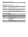
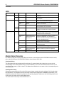
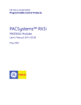
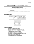
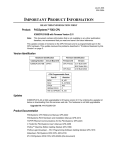
PACSystems* RX3i
IC695PBM300
PROFIBUS Master Module
GFK-2359D
June 2010
The PACSystems * RX3i PROFIBUS Master Module, IC695PBM300, allows the RX3i
CPU to send and receive data on a PROFIBUS-DP network.
The IC695PBM300 module provides the following PROFIBUS communications
features:
PROF I B US OK
NETWORK
MOD STATUS
Supports all standard data rates
Supports a maximum of 3,584 bytes of input data and 3,584 bytes of output data
Supports a maximum of 125 PROFIBUS-DP slaves
PBM300
PROFIBUS MASTER
Supports a maximum of 244 bytes of input data and 244 bytes of output data for
each slave
Supports Sync and Freeze modes
Supports DP-V1 Read, Write and Alarm messages
Has PROFIBUS-compliant module and network status LEDs
STATION ADDRESS
The PROFIBUS Master module requires an RX3i CPU with firmware version 2.9 or
later. This module must be located in an RX3i Universal Backplane.
The PROFIBUS module receives its firmware upgrades indirectly from the host
controller CPU using the WinLoader software utility. WinLoader is supplied with any
updates to the PROFIBUS module software.
Release Information
5-IGND
Version 1.04 of the IC695PBM300 RX3i PROFIBUS Master resolves the following
issues:
8-A
3-B
When multiple Lumberg devices (8in/4out) are connected to the bus and power is
removed from these devices, but the PBM300 remains powered, the inputs
assigned to the Lumberg devices will toggle between 1 and 0.
Configuring slaves with a large amount of parameter data returns the correct error
code when parameter data exceeds the available memory space.
The IC695PBM300 is field upgradable to firmware version 1.04 using the firmware
upgrade utility.
Upgrade Kit: 44A753033-G02
Release History
*
Catalog Number
Date
Firmware
Version
IC695PBM300-CC
June 2010
1.04
IC695PBM300-BC
May 2006
1.04
IC695PBM300-BB
Apr. 2005
1.02
IC695PBM300-BA
Feb. 2005
1.00
IC695PBM300-AA
Dec. 2004
1.00
Comments
Label change only. No change in functionality, performance or
compatibility.
indicates a trademark of GE Intelligent Platforms, Inc. and/or its affiliates. All other trademarks are the property
of their respective owners.
2
PROFIBUS Master Module, IC695PBM300
GFK-2359D
PBM300 Functional Compatibility
Subject
Description
Series 90™-30 PROFIBUS
Customers using existing Series 90-30 PROFIBUS products should review the
PACSystems RX3i PROFIBUS Modules User’s Manual, GFK-2301. Changes have been
made in items such as CommReq status words and data fields. This module will report
additional information in some instances, and less information in other instances. This
product also supports PROFIBUS DP-V1 functionality.
Programmer Version
Requirements
The IC695PBM300 can be configured and programmed with Machine Edition Logic
Developer PLC version 5.0 Build 3227 SP2 or later.
Total Configuration Size
The number and types of slave devices that can exchange data with the master are
constrained by various memory resources within the module. The amount of memory
available for the PROFIBUS configuration is affected by the number and types of slave
modules in the network configuration. The total slave configuration data size is limited to
approximately 9KB.
Data Sizes
The amount of data that can be configured on the IC695PBM300 PROFIBUS network
provides up to 3584 input bytes and 3584 output bytes.
DOIO Functionality
DOIO functionality is not supported in the embedded PROFIBUS interface at this time. The
DOIO function block returns an error if it is executed using the embedded PROFIBUS as a
target.
PLC C Toolkit Version
Requirements
Version 4.00 Build 50A1 or later of the PLC C Toolkit must be used for C programming.
Problems Resolved by this Revision
The following problems are resolved in version 1.04.
Subject
Description
Inputs to Lumberg devices
blink when devices are
powered down.
In previous versions, when multiple Lumberg devices (8in4out) are connected to the bus and
power is removed from these devices (but the PROFIBUS master remains powered), the
inputs assigned to the Lumberg devices will toggle between 1 and 0. This problem has been
corrected in version 1.04.
Incorrect error returned
when memory space
exceeded
Configuring slaves with large amount of parameter data returns the incorrect error code when
parameter data exceed the available memory space. This problem is resolved in version
1.04.
Problems Resolved in RX3i CPU (IC695CPU310)
The following problems were resolved in Release 3.00 of the RX3i CPU.
Subject
Description
PBM300 DPV1 Status data
When a slave module sends a DPV1 Alarm Request to the PBM300 master, the alarm
information is displayed in the DPV1 Status input area. The Sequence Number field in this
status area will only indicate the value 0 in release 2.9 RX3i CPU firmware, thus only slave
DPV1 Alarms with Sequence Number 0 can be properly indicated. This issue is corrected in
release 3.0 of the RX3i CPU firmware release.
Discrete memory types for
PBM300 COMMREQ
In a PBM300 COMMREQ request, the COMMREQ response reference memory area is
indicated in the request. Discrete reference memory types are now supported for the
response data area.
PROFIBUS Master Module, IC695PBM300
3
GFK-2359D
PBM300 Restrictions and Open Issues
Subject
Description
Get Master Status
CommReq returns “1 or
More Slaves Not in IO
Exchange Mode” on First
Scan
When a Get Master Status CommReq is called on the first scan of the PLC, the CommReq
may return a false positive saying that the PROFIBUS network has “1 or More Slaves Not in
IO Exchange Mode." The Get Master Status CommReq should not be called or relied upon
for any data during the first scan of the PLC.
Machine Edition Logic
Developer PLC displays
incorrect information for
Master Type and Device ID
The Network Settings window, which can be displayed while configuring a PBM300 in
Machine Edition, does not indicate correct information for Master Type and Device ID. This
information is only displayed to the user and does not affect any underlying configuration
information sent to the master module or its slaves. The Device ID (also known as
PROFIBUS Ident Number), if correctly displayed should be 0x0934.
Specifications: IC695PBM300
Environment
Storage temperature = -40°C to 85°C
Operating temperature = 0°C to 60°C
Backplane Compatibility
RX3i PCI
Backplane Current
Consumption
440mA @ 3.3VDC
Data rates
Supports all standard data rates (9.6 kBit/s, 19.2 kBit/s, 93.75 kBit/s, 187.5 kBit/s, 500 kBit/s,
1.5 MBit/s, 3 MBit/s, 6 MBit/s and 12 MBit/s)
Status Information Available
Slave Status Bit Array Table
Network Diagnostic Counters
DP Master Diagnostic Counters
Firmware Module Revision
Slave Diagnostic Address
Data Sizes
The amount of data that can be configured on the PBM300 PROFIBUS network provides up
to 3584 bytes input and 3584 bytes output.
For product standards and general specifications, refer to the PACSystems RX3i System Manual, GFK-2314.
4
PROFIBUS Master Module, IC695PBM300
GFK-2359D
LEDs
LED
PROFIBUS OK
NETWORK
MOD STATUS
Color
State
Frequency
Meaning
Green
Static On
NA
Module has power and backplane reset is
complete.
Off
NA
NA
Module does not have power or backplane reset is
not complete.
Yellow
Static On
n/a
Module is holding the PROFIBUS token and is
able to transmit PROFIBUS telegrams.
Flashing Noncyclic
Between 0.5 Hz and
100 Hz
Module is sharing the PROFIBUS token with other
master on the network.
Off
NA
Module is not configured or has not received the
token permission from the network.
Red
Static On
NA
Module has found a communication problem with
at least one network slave, usually connection
timeout.
Green
Flashing Cyclic
5 Hz
No error in configuration found; module is ready
for communication; it tries to open a connection to
a slave, but is not connected yet.
Flashing Noncyclic
3 times fast at 5 Hz,
8 times between 0.5
Hz and 1 Hz
Power Up: Configuration missing. For details on
hardware configuration, refer to Chapter 3.
Runtime: Firmware has found a critical problem,
such as a watchdog timeout.
Static On
NA
Module has established at least one connection to
another device on the network.
Flashing Cyclic
1 Hz
Module is in boot-loader mode and is waiting for
firmware download.
Yellow
Off
Flashing Cyclic
5Hz
Firmware download is in progress.
Flashing Noncyclic
3 times fast at 5 Hz,
8 times between 0.5
Hz and 1 Hz
Hardware or non-recoverable runtime error
detected, module may need to be replaced.
NA
NA
No power.
Module Status Information
For details on using the Communication Request function to communicate with the PROFIBUS master module,
refer to the PACSystems RX3i PROFIBUS Modules User’s Manual, GFK-2301.
Slave Status Bit Array
The Slave Status bit array contains a bit for each slave. If communication with a slave has no errors, the bit
corresponding to the slave (determined by its network address) is set. If the communication has errors or is not
occurring for any reason, the bit is cleared. The Master also maintains its own status in the bit corresponding to its
network address.
Slave Diagnostics ID Array
If diagnostics are pending, the first word of this two-word array contains the station address of the first slave that
has diagnostics. The diagnostics can be read using the Get Device Diagnostics COMMREQ (command 4). This
clears the word and the master then places the next pending diagnostic address into the Slave Diagnostics word.
If this word is zero there are no pending diagnostics.
The second word of this array is reserved and set to 0.
PROFIBUS Master Module, IC695PBM300
5
GFK-2359D
DPV1 Alarm Status Array
The 32-bit DPV1 Alarm Status array is used at the beginning of a scan to receive the station address of a slave
that has sent a DPV1 Alarm message. If another slave has sent a DPV1 alarm message, it is ignored until the first
one has been serviced, and will then appear in a subsequent scan. For details on the status format, refer to
“DPV1 Alarm Acknowledge COMMREQ” in GFK-2301.
Slave Configured Bits
This 128-bit array indicates which slaves on the PROFIBUS network are configured. Each slave has a
corresponding bit in this array. A slave's configuration status address equals Start Address + Station Address of
the slave. For example, if the configuration status bits are mapped to %I00001, the status for the slave at Station
Address 5 would be found at %I00001 + 5=%I00006.
Slave Diagnostic Bits
This 128-bit array indicates which slaves on the PROFIBUS network have diagnostic data available. The
diagnostics can be read using the Get Device Diagnostics COMMREQ (command 4).
Each slave has a corresponding bit in this array. A slave's diagnostic status address equals Start Address +
Station Address of the slave. For example, if the configuration status bits are mapped to %I00001, the status for
the slave at Station Address 5 would be found at %I00001 + 5=%I00006.
Connecting the Module to the PROFIBUS Network
The module contains a standard female DB9 connector, labeled “PROFIBUS,” that can be connected to a
PROFIBUS bus terminal that complies with EN 50170.
The PROFIBUS module has no built-in termination. If termination is required, you must use a bus terminal that
has built-in selectable termination.
PROFIBUS DB-9 connector recommendation: Siemens 6ES7-972-OBB50-OXAO (12MB)
Caution
Do not connect any devices to the +5V pin (pin 6). It is to be used for
termination purposes only. Doing so could damage equipment or cause
erratic behavior.
Installation in Hazardous Locations
1.
EQUIPMENT LABELED WITH REFERENCE TO CLASS I, GROUPS A, B, C & D, DIV. 2 HAZARDOUS
LOCATIONS IS SUITABLE FOR USE IN CLASS I, DIVISION 2, GROUPS A, B, C, D OR NONHAZARDOUS LOCATIONS ONLY.
2.
WARNING - EXPLOSION HAZARD - SUBSTITUTION OF COMPONENTS MAY IMPAIR SUITABILITY FOR
CLASS I, DIVISION 2.
3.
WARNING - EXPLOSION HAZARD - DO NOT DISCONNECT EQUIPMENT UNLESS POWER HAS BEEN
SWITCHED OFF OR THE AREA IS KNOWN TO BE NON-HAZARDOUS.