1
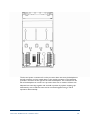
Demo Unit User Manual (AADvance Controller)
The processor base unit provides the electrical connections between the T9110
processor modules, and the rest of the controller modules and has the following
connections:
Command and response bus connections for up to 48 I/O modules
Inter-processor links
Two Ethernet 100 BaseT connectors per processor
Two serial data connections per processor
Dual +24v System power
Ground stud
Program enable key
The processor base unit holds the IP address of each processor module separately in a
BUSP. This means that you can remove a defective processor module and install a new
one without needing to set up the IP address of the new module.
T9300 I/O Base Unit (3 way)
The AADvance controller has T9300 I/O base units for the I/O modules. An I/O base
unit supports up to three I/O modules (of any type), and their associated termination
assemblies.
It contains a passive backplane that provides the electrical connections between the
I/O modules and the T9100 processor base unit; i.e. the command and response buses
and the system power.
1-8
Document: 553850 Issue 1.2: March 2011
The bus and power connections from the processor base unit enter the backplane at
the left connector and are routed direct to the module connectors. The backplane
provides a connector at the right for the next I/O backplane. The connection to the
left of the backplane can connect to a processor base unit or another I/O base unit.
Adjacent base units clip together and are held in position by a plastic retaining clip.
Alternatively rows of I/O base units can be connected together using a T9310
expansion cable assembly.
Document: 553850 Issue 1.2: March 2011
1-9