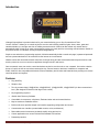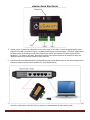
1
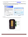
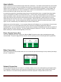
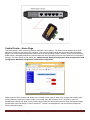
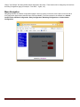
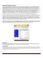
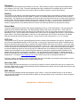
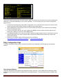
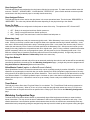
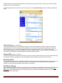
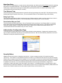
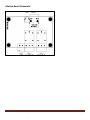
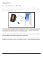
uSwitch™ Installation
and Operating Manual
uSwitch Installation and Operating Manual
Page 1
Table of Contents
Introduction.............................................................................................................................................................................. 3
Features .................................................................................................................................................................................. 3
Installation Guidelines (Read before Installing) ...................................................................................................................... 4
uSwitch Quick Start Guide ...................................................................................................................................................... 5
About uSwitch ......................................................................................................................................................................... 7
Power Supply Connection ....................................................................................................................................................... 7
Relay Connection .................................................................................................................................................................... 7
Network Connection ................................................................................................................................................................ 7
Control Center – Home Page .................................................................................................................................................. 8
Menu Navigation ..................................................................................................................................................................... 9
Control Center (Relay 1- Momentary Mode) ......................................................................................................................... 10
Control Center (Relay 1 Watchdog Mode, Startup Delay phase) ......................................................................................... 10
Control Center (Relay 1 Watchdog Mode, Ping Delay phase) ............................................................................................. 11
Control Center (Relay 1 Watchdog Mode, pinging phase) ................................................................................................... 12
Control Center (Relay 1 Watchdog Mode, ping retry phase) ................................................................................................ 13
Control Center (Relay 1 Watchdog Mode, auto reboot countdown phase) .......................................................................... 13
Network Configuration Page ................................................................................................................................................. 14
Relay Configuration Page ..................................................................................................................................................... 16
Watchdog Configuration Page .............................................................................................................................................. 17
Authorization Configuration Page ......................................................................................................................................... 19
Security Notes ....................................................................................................................................................................... 19
uSwitch Board Schematic ..................................................................................................................................................... 20
Access Control to Electronic Door Strike .............................................................................................................................. 21
Hard Wired Network Connection........................................................................................................................................... 22
Wireless Network Connection ............................................................................................................................................... 23
Troubleshooting: ................................................................................................................................................................... 23
Appendix A: Factory Default Settings .................................................................................................................................. 24
Network Configuration:.......................................................................................................................................................... 24
Relay Configuration:.............................................................................................................................................................. 24
Watchdog Configuration:....................................................................................................................................................... 24
Appendix B: Specifications................................................................................................................................................... 25
Product Safety: FCC Statement ............................................................................................................................................ 26
Warranty ................................................................................................................................................................................ 26
Trademark and Copyright Information .................................................................................................................................. 27
uSwitch Installation and Operating Manual
Page 2
Introduction
VideogeniX specializes in practical solutions for your network allowing you to Stay Connected and Take
Control. uSwitch™ allows you to control any device over the web including modems, lights, sirens, doors, gates and
cameras whether you are right next door or halfway across the world. uSwitch can also restart any network device
automatically when it locks up or stops communicating, saving you costly and time consuming manual reboots. uSwitch is
the perfect solution for industrial, security and personal applications.
Simple to use and with no programming required, uSwitch automatically builds a control web page, is password protected
and can operate stand alone or be controlled via the Internet or a local intranet.
uSwitch comes with removable terminal connectors for simple wiring and two electromechanical relays that can be used
as a dry contact or to turn on controls or appliances through its built in web server.
Once connected, users can monitor, control and reboot any device over the web or over a network, from under a desk to
the top of a pole, as well as at a remote construction site, summer homes or business. In addition to computers and
iPads, uSwitch is also compatible with Android, iPhone, Blackberry and all other web based devices providing true remote
control anywhere and anytime.
Features
•
Plug-and-Play
•
Simple to Use
•
Two dry contact relays (15A@120Vac, 10A@250VAC), (15A@120VDC, 10A@ 250VDC) for direct connection to
load. (Not designed for devices with large inrush current)
•
No programming required
•
uSwitch Auto Discovery Software
•
Controllable via computers, cell phones, iPads and other web and network devices
•
May be used as a standalone device
•
Built-in web server provides simple user interface supporting configuration and control.
•
Customizable user interface (customizable controls, colors, and buttons).
•
Removable terminal connectors (included) simplify wiring and service
•
Custom applications can control uSwitch with standard CGI interface.
•
Password protection
uSwitch Installation and Operating Manual
Page 3
•
Supports fixed IP or DHCP, and Dynamic IP with port forwarding
•
Selectable TCP ports for proxy server and NAT applications
•
10/100 Ethernet connectivity.
•
Built-in automatic watchdog mode on each relay; each relay has three independent, user assignable and pingable URL options (Only device in the market with patented Watchdog).
•
Watchdog mode timers and counters fully configurable
•
Momentary and pulse timers fully configurable.
•
Relay power on state user configurable (Closed, Open, Previous)
•
Extremely small footprint
•
Low power consumption
•
Manual relay switching mode
•
Enterprise grade software and remote monitoring packages offered.
•
User customizable relay state colors and state text
•
User customizable text fields for relay names
•
Relays can be controlled from other uSwitch devices over the Web
•
Universal Voltage input 12-24VDC
•
Great documentation and support
Installation Guidelines (Read before Installing)
Opening the uSwitch enclosure or tampering will void the warranty.
1. uSwitch is not weatherproof (do not install outdoors without proper environmental enclosure).
2. uSwitch must be installed by qualified personnel.
3. uSwitch is not designed to run in a radioactive environment
4. uSwitch must not be used for medical, lifesaving purposes, or for any purpose where its failure could cause
serious injury, loss of life, or create significant financial losses.
5. uSwitch must be correctly wired. Incorrect wiring could result in damage to uSwitch or the device to which it is
wired.
uSwitch Installation and Operating Manual
Page 4
uSwitch Quick Start Guide
1.
uSwitch can be connected to a DC power source in the range of 12-24Vdc. Connect an appropriate DC power
supply to the + and - Terminals in Figure 1 (regulated power supply is recommended). The power supply should
be rated to meet the operating current of the uSwitch (see uSwitch specifications for power requirements in
appendix C). As shown in the photo, the positive terminal is the terminal closest to the outside unit edge; the
negative terminal is the terminal closest to relay connectors.
2. Connect an Ethernet cable between the uSwitch Ethernet port and an Ethernet port on the network switch/router.
Connect a computer to the network switch/router. (See diagram below)
3. Set up a computer on the same network/subnet as the uSwitch. To do this, set the IP address of the computer to
192.168.1.x with subnet of 255.255.255.0 (x can be any unused address on that network 2-254).
uSwitch Installation and Operating Manual
Page 5
4. Connect to the uSwitch by entering the factory default IP address (http://192.168.1.199) into the address bar on
your computer’s browser.
5. If this is the first time you are logging on to the uSwitch from your computer, a password dialog box will appear
(see examples below). Enter “admin”, for both the User name and Password fields (all lower case). Once logged
on these can be changed in the section Authorization Configuration Page.
Windows Vista
Windows 8
6. Press “OK”.
7. Connect the relay contacts as desired (refer to the diagram below for relay connections).
uSwitch Installation and Operating Manual
Page 6
About uSwitch
uSwitch contains two electro-mechanical relays and a built in web server. The uSwitch’s web interface can be controlled
and/or monitored over any IP network including private networks, IP-based industrial control networks, and the Internet.
uSwitch can be controlled from a web browser or via a custom application third party application. Using standard CGI,
uSwitch can operate stand-alone or can be controlled from a remote or local web browser. It can be used to operate
access control devices, lights, pumps, valves, locks, motors, etc.
It can also be programmed to automatically restart electronic devices that have frozen, or stopped functioning properly
(even if communication to uSwitch or device has been lost). It can be used to remotely reboot servers, computers,
cellular and satellite modems, and other devices over the Internet - either LAN or WAN. uSwitch relays can be wired in
series with the power source of the device and switch the power on and off manually. Another option is to connect
uSwitch directly into a device’s reset circuit. In this configuration, uSwitch does not power down the device, but simply
causes the device to reset. All reboot methods have different requirements in physical connection and setup. A fourth
option is to wire a uSwitch relay to an isolated relay to control an isolated circuit.
uSwitch has a built-in Web Interface. You can access uSwitch by its IP address if you are connecting to it from the same
network or if you are on a remote WAN by the URL of the LAN and or the uSwitch’s assigned port (with port
forwarding/NAT). It can be accessed on networks with both static and dynamic IP addresses (in the case of a dynamic IP
address a dynamic IP client is required). The factory default settings for uSwitch are: 192.168.1.199 as its IP address, a
default network port of 80 and a default gateway is 192.168.1.1.
Power Supply Connection
Connect an appropriate DC power supply to the Vin+ and Gnd Terminals as shown below (regulated power supply
recommended). The power supply should be rated to meet the operating current of uSwitch (specified in Appendix B).
Relay Connection
When connecting to the relay contacts make sure not to exceed the specified load ratings for relay contacts (load ratings
per spec. in Appendix B).
Network Connection
Connect uSwitch Ethernet port to a 10 base-T or 100 base-T switch, router or cell modem/gateway (per diagram below).
For configuration, uSwitch can also connect directly to the Ethernet port on a computer using a crossover/null-modem
cable. Otherwise, for connection through standard communication equipment a straight cable should be used.
uSwitch Installation and Operating Manual
Page 7
Control Center – Home Page
This is the uSwitch’s main control and interface, called the “Control Center”. The Control Center appears when the IP
address of a uSwitch is first entered into a browser. This screen provides manual relay control and status information
based on the various supported operating modes and inputs (see operating modes in uSwitch Control Center Operating
Modes section). Navigating between the uSwitch features is done by clicking on the blue menu buttons on the left side of
the page. The menu options for the uSwitch are: uSwitch Control, Network Configuration, Relay Configuration, GPIO
Configuration, Watchdog Configuration, Authorization Configuration.
Selecting the red “Click to switch ON” button on the “Control Center” page for either relay, energizes the selected relay
forcing a normally closed (NC) contact to open or a normally open (NO) contact to close. The button’s color will
simultaneously change from green to red (unless custom colors have been selected from the Relay Configuration page)
and the button’s text will change to “Click to switch OFF” (unless “user assigned text” has been similarly changed on
Relay Configuration page).
uSwitch Installation and Operating Manual
Page 8
“Relay1” and “Relay2” are factory default names assigned to the relays. These names can be changed by the user from
the Relay Configuration page (for example, “Front Door”, “Lights”, etc.)
Menu Navigation
Navigating between the uSwitch configurations pages is done by clicking on the blue menu buttons on the left side of
every page (each page has the identical menu choices available). The menu options for the uSwitch are, uSwitch
Control Center, Network Configuration, Relay Configuration, Watchdog Configuration and Authorization
Configuration.
uSwitch Installation and Operating Manual
Page 9
uSwitch Control Center Operating Modes
Control Center (Relay 1- Momentary Mode)
The image below shows the Control Center with relay 1 configured as a 20 second momentary (or pulsed) relay (a relay is
configured into momentary mode from the Relay Configuration page). In this case each time the relay 1 button is clicked,
the relay changes its state, counts down to 0 (currently 18) and then changes back to its starting state. To change the
relays starting state, turn the momentary option off (on the Relay Configuration page), manually change the state of the
relay (on the Control Center page) to the desired starting state and put the relay back into momentary mode (on the Relay
Configuration page).
Control Center (Relay 1 Watchdog Mode, Startup Delay phase)
The image below shows the Control Center with relay 1 configured in Watchdog Mode (a relay is placed in watchdog
mode from the Relay Configuration page). In this case watchdog mode has begun its initial startup time countdown
specified in the startup delay before testing for connectivity, currently 291 seconds remain before testing begins. A
minimum recommended startup countdown time of five minutes (300 seconds) is recommended.
uSwitch Installation and Operating Manual
Page 10
Control Center (Relay 1 Watchdog Mode, Ping Delay phase)
The image below shows the Control page with relay 1 configured in Watchdog mode during the, “Ping Delay” phase. This
is the time delay between successive pings to the same URL. A recommended time of 90 seconds for the “ping delay” is
suggested.
uSwitch Installation and Operating Manual
Page 11
Control Center (Relay 1 Watchdog Mode, pinging phase)
The image below shows the Control Center with relay 1 configured in Watchdog Mode. In this instance the uSwitch is
attempting to ping the URL “google.com” assigned for relay 1 to determine if relay 1 needs to be cycled.
uSwitch Installation and Operating Manual
Page 12
Control Center (Relay 1 Watchdog Mode, ping retry phase)
The image below shows the Control Center with relay 1 configured in Watchdog Mode, the uSwitch is attempting to ping
one of the URL’s specified on the Watchdog Configuration Page after two consecutive failed ping attempts to that same
URL (note status field for Relay 1 shows this is the 3rd attempt, meaning first two attempts failed).
Control Center (Relay 1 Watchdog Mode, auto reboot countdown phase)
The image below shows the Control Center with relay 1 configured in Watchdog Mode. The uSwitch automatically is
cycling the relay after failing to get responses from the URLs specified in the Watchdog Configuration page for Relay 1.
The screen shot below shows the reboot countdown time remaining and will turn power back on to device when the count
reaches 0. The amount of time for the relay to be cycled is as specified in the Relay Cycle Time field on the Watchdog
Configuration page.
uSwitch Installation and Operating Manual
Page 13
Network Configuration Page
Network settings and control options are modified from the Network Configuration page. If multiple uSwitch devices are
used on the same network, connect only one at a time and configure the IP address of each unit before connecting the
next uSwitch to the network. This prevents having two network devices on the same network with identical network
addresses (creating an IP address conflict). It is a good idea to clear the Address Resolution Protocol Cache (ARP) each
time you swap uSwitch units on the same network. This is because each uSwitch has a factory default IP address
(192.168.1.199) and if the cache is not cleared an IP address conflict could occur if two IP addresses are associated with
two different hardware MAC addresses. To clear the ARP cache on a Windows PC type “arp –d inet addr” in a
DOS/Windows command prompt window (“arp -d –a” as super user on Apple OSX). Once you have changed network
settings on the uSwitch you must cycle power on the new uSwitch before the network settings will take effect.
You can use a proxy server to connect multiple devices to the Internet using a single static or dynamic IP resolved
address. This can be done using most consumer or industrial grade routers. If a proxy server environment is to be set up,
each uSwitch will not be accessible from the internet until the proxy server (router) is configured with the unique and
specific port number and IP address assigned to each uSwitch on its local area network (LAN). This is a form of Network
Address Translation (NAT) also called port forwarding or virtual port addressing. To determine how to set up the proxy
server for port forwarding (also called NAT) consult the proxy server’s manual.
(Note: When multiple uSwitch devices are installed on the same local area network, each must have its own unique IP
address. Every uSwitch comes with a factory default IP address of 192.168.1.199. If multiple uSwitch devices are used,
assign a unique IP address to each, such as: 192.168.1.195, 192.168.1.196, 192.168.1.197, etc.)
Host Name
This configurable field represents a user chosen name for your uSwitch. It will be used when reporting information from
this device and in any status logs. It is a virtual name for the current uSwitch device.
Enable DHCP
This checkbox should be selected when the user chooses to have a DHCP server automatically assign IPV4 addresses to
the uSwitch. DHCP is not recommended as router assigned addresses will change over time making it difficult to know
the address of any given uSwitch at any given time.
uSwitch Installation and Operating Manual
Page 14
IP Address
This specifies the IPV4 address of the uSwitch on the LAN. (Each uSwitch is factory configured with the default static
IPV4 address of 192.168.1.199). This static LAN address should be modified to be consistent with the LAN’s subnet.
When using multiple uSwitch devices on the same LAN each uSwitch must have a unique IPV4 address.
Gateway
This specifies the IP address of the gateway (typically router/cell modem) which is responsible for creating the LAN and
connecting to outside networks and or the WEB. If unknown, the Gateway address can be obtained from the network
administrator. The Gateway is the LAN address of the device that routes the internal LAN to an outside network (WAN) or
another subnet. The factory default gateway setting for the uSwitch is 192.168.1.1. This must be the assigned address of
the device that routes the network on which the uSwitch is connected for uSwitch features to function correctly. For
instance, pinging devices in Auto Reboot mode will not work if the Gateway address is not programmed correctly.
Subnet Mask
The subnet mask identifies a specific LAN’s private addressing scheme on a TCP IPV4 network. This can typically be
obtained from the network administrator. By default uSwitch subnet mask is set to 255.255.255.0. Each of the four,
three-digit fields in the subnet mask represents an IPV4 address field. Each of these fields represents a byte worth of
addressing (1-255). Any bit positions in the address with a value of zero are accessible on the subnet. Any bit positions
with a value of 1 are fixed (unchangeable) on the LAN. In the subnet mask, 255.255.255.0, the first three IP address
fields are fixed and the last IP field may vary from 1 to 255 (a value of 255 is equivalent to 11111111 in binary).
HTTP Port
This specifies the HTTP port (for typical WEB access) used for outside communications to the uSwitch. By default, this
port is set to 80 (standard access port for HTTP devices). A unique port is required for each uSwitch if outside network
access is desired through a single router or gateway and multiple uSwitch devices are on its network. In this case, each
uSwitch device would be assigned a different port (for example 41, 42, 43, etc). With unique ports assigned to a uSwitch,
a router will forward all communication for that device directly to it without the outside network having any knowledge of
the internal addressing scheme on the LAN (private IPV4 addresses are not accessible to the outside world/cloud). Each
uSwitch may be accessed from the cloud on its private network by entering the routable/resolvable IP address of the
gateway with the specific port assigned to the uSwitch. Any port (besides port 80) assigned to a uSwitch requires all
outside communications to that uSwitch to reference it via its gateway’s resolvable IP address or URL and that uSwitch’s
assigned port. For instance www.videogenix.com:42 (for a device on port 42) or www.MyHomeRouter:41.
This field is used by the uSwitch to resolve outside URLs that may be included in the automatic reboot options or device
firmware whose actual IP addresses are unknown inside the LAN.
Secondary DNS
This secondary DNS (Domain Name Server) is used by the uSwitch to resolve outside URLs that may be included in the
automatic reboot options or device firmware whose actual IP addresses are unknown from the private network just in case
the primary DNS is not available.
MAC Address
This is the physical address permanently assigned a given uSwitch. It cannot be modified however it can be used to
verify which LAN IP address is connected to which uSwitch by executing either an arp -a command, or when running the
uSwitch discovery utility.
MAC Address <40:D8:55:16:3C:99>
uSwitch Installation and Operating Manual
Page 15
To access a uSwitch remotely from an outside network, WAN or the internet you will need to set up port forwarding (also
called NAT or Virtual Port addressing) in your router or gateway. You can set this up from your router’s configuration
page as follows:
1. Find the Port Forwarding/Virtual Server/NAT configuration in your router and map a unique port number to each
uSwitch by specifying the uSwitch’s private IP address on the private network.
2. Use the identical port provided to the router for a given uSwitch and assign it to the uSwitch from the uSwitch’s
Network Configuration screen.
3. If you are on a static IP line you may use a 3rd Party free DDNS provider to register a Domain Name for your
Router (URL). Map your router to the free DDNS provider.
4. If the address assigned to your router by your ISP is dynamic (changes regularly) than you will need to set up the
dynamic DNS page of your router to map the URL to a Dynamic IP Name Server (consult your router’s user
configuration manual).
5. Browse to your USwitch using the following protocol from a browser;
http://myNetworksURL:myuSwitchPortNumber (i.e. http://myHomeRouter:8000)
Relay Configuration Page
The Relay Configuration allows a user to customize how each relay is displayed, controlled and any unique startup
features.
User Assigned Names
These two configurable fields represent user assigned names for each relay. Once modified all text identifying “Relay1”
or “Relay2” in the browser interface is modified to the new assigned names. The factory default names are Relay1 and
Relay2
uSwitch Installation and Operating Manual
Page 16
User Assigned Text
This field specifies the text assigned to the relay button reflecting its current state. The state names available under this
menu are “ON/OFF”, “OPEN/CLOSED”, “LOCK/UNLOCK”,”START/STOP”. (Note: uSwitch terminal connectors provide
connections to the relay’s normally open or normally closed connection).
User Assigned Colors
This field specifies the colors used on the relay button in its current operational state. The choices are “RED/GREEN” or
“GREEN/RED”. The colors may indicate different states depending on the physical wiring to the uSwitch
Power On State
This selection dropdown box configures the initial power on state of the relay. The options are OFF, ON and LAST.
1. OFF - Relay is de-energized each time uSwitch powers on.
2. ON - Relay is energized each time uSwitch powers on.
3. LAST - Relay is put in the state it was in when the uSwitch last had power on.
Momentary (sec)
This second timer field puts a relay into momentary (pulse) mode. When Momentary is set to zero, the relay is in latching
mode. Clicking on the relay’s control button changes its state to the opposite state leaving it latched indefinitely. A nonzero value in the Momentary field puts the relay in momentary/pulse mode. In this mode, each time the relay is clicked it
retains the new state only for the number of seconds specified in the Momentary field. After the second counter (on the
display for the relay) elapses the relay switches back to its original state. (Note, if wiring a uSwitch in parallel with another
physical momentary switch, such as a garage door opener, the relay must be put into momentary/pulse mode. If not
whenever uSwitch relay is closed the pre-existing switch will have its functionality blocked). A single relay cannot be
programmed to Ping Auto Reboot and Momentary Mode at the same time).
Ping Auto Reboot
If this box is checked the selected relay will act as an automatic watchdog reboot device and its state will be automatically
controlled as specified in the settings from the Watchdog Configuration page. (a single relay cannot be programmed to
Ping Auto Reboot and Momentary Mode at the same time).
Allow Master Control (applies to uSwitchPro and uSwitch)
When Allow Master Control is checked the selected relay can be controlled remotely by another uSwitchPro. If a remote
uSwitchPro is programmed to control this relay (on remote uSwitchPro’s GPIO Configuration page) the state of the relay
will synchronize to the GPIO (input) from the remote uSwitchPro. This is useful if a remote input is desired to drive a relay
on a different uSwitch. For instance a uSwitch input to lock down or open a door that is not physically connected to the
uSwitch with the input on it. uSwitchPro’s can be set up to remotely control a relay on a standard uSwitch or another
uSwitchPro.
Timed Reboot
This field only has an effect when “Ping Auto Reboot” is not checked. The “Timed Reboot” field can be programmed to
either OFF, 12 or 24 (hours). When in 12 hour or 24 hour mode the relay will switch states once every 12 or 24 hours.
The total duration of the pulse time will be as specified in the “Relay Cycle Time” field on the Watchdog Configuration
page.
Watchdog Configuration Page
The Auto Reboot Ping feature allows uSwitch to automatically detect failed equipment and reboot or restart it without
human intervention. You may set one to three IP addresses or URLs to be periodically contacted for each relay. If the
uSwitch determines a communication problem exists between these devices, the uSwitch can automatically reboot any
attached devices by temporarily pulsing the assigned relay that may have the locked up device’s power running through it.
uSwitch Installation and Operating Manual
Page 17
uSwitch has been successfully deployed with: IP cameras, kiosks, web signs, cellular routers, Servers, DSL and cable
modems, RTUs, control sensors, etc.
The following parameters are effective only when uSwitch is set to Auto Reboot Ping mode (in the Relay Configuration
page).
URLs to Ping (Relay 1 and Relay 2)
These three (3) fields contain the IP addresses of remote or local devices/URLs that uSwitch will ping in determining
operational failure. This may include the static IP address or remote IP of devices that will be tested (router, computer,
Kiosk, network camera, or a device on the opposite side of a communications link). This is useful to auto reboot
communications devices such as CSU/DSUs/RTUs, cameras, satellite modems, routers, reclosures, power meters etc. If
fewer than three URL fields are required fields can be blank and will be ignored.
Verify all URLs
(Relay 1 and Relay 2)
The Verify all URLs specifies whether response from pings to all URLs (specified in URLs to Ping) for an associated relay
are required or whether a response from any single URL is required to determine device failure or success.
Max Ping Failures
If no ping responses are returned for Max Ping Failures (consecutive) then the selected relay will be cycled (forcing a cold
reboot of the connected device). A ping failure occurs if any single device fails to respond when Verify all URLs is
checked, or when no devices respond if Verify all URLs is unchecked.
Max Reboot Attempts
After “Max Reboot Attempts” without device reconnection, the uSwitch exits “Auto Reboot” mode and enters “Device Fault
Mode”. (During “Device Fault mode” the uSwitch stops cycling the relay to the attached device for the specified Fault
Mode Time. Fault mode prevents continuous power cycling on a device after detecting that simple power cycling is not
curing the communication failure).
uSwitch Installation and Operating Manual
Page 18
Mode Start Delay
When uSwitch is first powered on, or after a device reboot attempt, the uSwitch will wait Start Delay time before restarting
ping tests to renew failure detection. This start delay gives a newly power cycled device time to fully boot up establish
connections to external devices and get into steady-state operating mode before the uSwitch starts testing it. (The
recommended minimum Start Delay is 5 minutes).
Time Between Pings
This is the frequency (in seconds) between consecutive device ping attempts to the same URL. This field prevents ping
flooding and allows for network down times. (The recommended minimum Time Between Pings is 90 seconds).
Relay Cycle Time
This is the time period that the uSwitch switches the relay off before switching it back on (giving a device time to have a
clean power shutdown and re-power). (The recommended minimum Relay Cycle Time is 5 seconds)
Period before Retry on Fault
This is the time that uSwitch will remain in “Device Fault Mode” before returning to “Auto Reboot Mode” to re-attempt
device startup after the specified Max Reboot Attempt consecutive failures have occurred. This feature prevents the
continuous cycling of power on a device that may not have a power cycle curable communication failure. (The
recommended minimum Period before Retry on Fault is 4 hours)
Authorization Configuration Page
The Authorization Configuration Page is used to change uSwitch access passwords. A password is required on initial
login to uSwitch. Passwords may be up to 23 characters and numbers. We recommend difficult passwords of at least 8
characters including both letters and numerals.
Security Notes
uSwitch is an extremely secure networking control device. It does not support terminal or file transfer programs
(TFTP/FTP). This means it is not possible for someone to ‘break in’ to it and access other devices on your local network.
uSwitch does not support remote firmware updates so it is not possible for someone to remotely install malicious software.
As with any device to be installed on a network, there are some security precautions that should be observed. If uSwitch
is installed on the Internet, it is recommended that passwords be secure (at least 8 characters in length with a
combination of upper case letters, lower case letters, and numbers). For additional security, a firewall may be used to
limit access only to selected IP addresses. Another option may be to set up a Virtual Private Network (VPN) between the
network where uSwitch resides and the client machine (web browser, second uSwitch, etc.).
uSwitch Installation and Operating Manual
Page 19
uSwitch Board Schematic
uSwitch Installation and Operating Manual
Page 20
Configurations
Access Control to Electronic Door Strike
The following is a configuration where uSwitch is used to provide access control. When connecting to door strikes a
reverse-bias diode is recommended. In this example, a reverse-bias diode is connected in parallel with the lock to protect
the relay contacts from the inductive kickback that can occur when the lock is switched. A variety of diodes is available
and can be ordered either online or directly from us. (For AC door access control no diode is necessary, for DC powered
devices a 60V p/p diode is recommended).
For loads greater than those rated for the uSwitch’s internal relays, or when connected to devices with high inrush or peak
current surge an external relay should be used with the uSwitch triggering the relay. The illustration below shows how a
high current motor or other high load device can be controlled using by wiring to an external relay. A variety of external
relays is available and can be ordered either online or directly from Videogenix.
When relays switch inductive loads such as motors, transformers, relays, etc., electricity will arc across the internal relay
contacts each time the contacts open. Over time this causes wear on the relay contacts which can shorten their life span.
When switching a high inductive load, it is recommended that simple relay contact protection devices be used. To be
economically feasible uSwitch cannot provide relay protection for all possible loads.
For applications with excessive loads, the following diagram shows a relay contact protection circuit for DC and for AC
applications. For component values required to provide sufficient contact protection for a specific application, consult the
application reference. Note: for DC circuits a diode is used and for AC circuits an RC circuit across the load can be used.
uSwitch Installation and Operating Manual
Page 21
Connection to an External Relay
Hard Wired Network Connection
Using standard Ethernet cabling, connect uSwitch’s Ethernet port to a 10 Base T or 10/100 Base T Ethernet connection
such as a network switch, router or cellular mode. To connect directly to a computer, use a “crossover”/”Null Modem”
cable. For connection to a router or switch, a standard “straight-through” cable is recommended.
Wired Network Connection
uSwitch Installation and Operating Manual
Page 22
Wireless Network Connection
To operate uSwitch in a wireless network environment, connect the uSwitch Ethernet port to a wireless repeater or bridge.
The wireless bridge in turn connects to the wireless network. The wireless Ethernet Bridge or router must be properly set
up for the wireless network first. This information is contained in the End User documentation for the wireless networking
device. A variety of wireless repeaters is available and can be ordered either online or directly from us.
Wireless Network Connection
Troubleshooting:
Before returning a device test the power input transformer to uSwitch. This can easily be done by swapping out with a
known working power transformer.
uSwitch Installation and Operating Manual
Page 23
Appendix A: Factory Default Settings
In the event that the IP address or passwords are forgotten and you cannot log in to uSwitch, you can reset uSwitch to its
factory default settings. With power press the reset button for about 5 seconds (you should feel or hear the reset pin
click). After approximately 5 seconds, release the reset button. Wait 30 seconds then cycle power on uSwitch. Now all
settings should be restored to factory default settings.
Network Configuration:
Host Name:
Relay 1 Name:
Relay 2 Name:
DHCP:
IP Address:
Subnet Mask
Gateway:
Primary DNS
Secondary DNS
HTTP Port:
MAC Address:
USWITCH_BOARD
Relay1
Relay2
Off
192.168.1.199
255.255.255.0
192.168.1.1
8.8.4.4
8.8.8.8
80
Predefined at Factory (non-configurable)
Relay Configuration:
User Assigned Name
User Assigned Text
User Assigned Colors
Power Up State:
Momentary(s):
Sync with Local GPIO
Allows Master Reboot
Timed Reboot:
Relay1/Relay2
On (Off)
Red/Green
Last (sets relay to return to previous state after each uSwitch power cycle)
0 (non-momentary)
unchecked
unchecked
Off
Watchdog Configuration:
URLs to Ping (all relays)
URL Primary:
URL Secondary:
URL Tertiary
Verify All URLs:
8.8.8.8
4.2.2.2
192.168.0.1
Unchecked
Auto Reboot Counters
Max Ping Failures:
Max Reboot Attempts
3
3
Auto Reboot Timers
Mode Start Delay:
Time Between Pings:
Relay Cycle Time:
Period Before Retry on Fault:
5 min, 0 seconds
1 min, 30 seconds
5 Seconds
4 hours, 0 minutes, 0 seconds
User Authorization Page
User Name:
Password:
“admin”
“admin”
uSwitch Installation and Operating Manual
Page 24
Appendix B: Specifications
AC
Relay Capacity: 7.5 A Max at 105-125 VAC, 5 A Max at 210-240 VAC
Power Requirements:
Model uSwitch
Voltage: 12VDC – 24VDC%
Model uSwitch
Standby Current
(Relays OFF) - 58mA
One Relay on - 92mA
Both Relays on - 126mA
Relay Ratings:
Rated Carrying Current: 15A @ 125VAC, 10A @ 250VAC, 15A @ 24VDC
Max Current: 15A
Max Voltage: 240VAC, 110 VDC
Relay Performance
Relay Control Options: ON/OFF, Pulsed, Automatic, Momentary
Contact Resistance <50m ohms (initial value)
Contact Material: Ag alloy
Max Switching Voltage: 240VAC, 110VDC
Max Switching Current 20A
Mechanical life (rated load) 10,000,000 ops.
Electrical life (rated load) 100,000 ops.
Networking:
Network: 10/100 Base-T, IPv4
Network Setup: static IP address assignment, DHCP, HTTP port selectable
Network Connector: 8-pin RJ-45 socket
Connectors:
Power/Input: 2-position, removable terminal strip, 3.81mm terminal spacing
Relays:
3-position (Normally Closed, Normally Open, Common) removable terminal, 3.81mm terminal spacing
Ethernet:
8-pin RJ-45 socket
LED Indicators: (on Ethernet jack)
-Network linked
-Network activity
Physical:
MTBF 360,000 hours
Temperature 0 – 50 degrees C (-30C , +80C)
Size: .4.2 in (106 mm) long, 2.15 in (55mm) wide, 1.0 in(25 mm) deep
Weight: 4.3 oz (122 grams)
Password Settings:
Password protection on setup page: Yes
uSwitch Installation and Operating Manual
Page 25
Product Safety: FCC Statement
This device complies with Part 15 of the FCC Rules. Operation is subject to the following two
Conditions:
• This device may not cause harmful interference.
• This device must accept any interference received, including interference that may cause undesired operation.
Warning:
This equipment has been tested and found to comply with the limits for a Class B digital device, pursuant to Part 15 of the
FCC Rules. These limits are designed to provide reasonable protection. This equipment generates uses and can radiate
radio frequency energy and, if not installed and used in accordance with the instructions, may cause interference to radio
communications. However, there is no guarantee that interference will not occur in a particular installation. If this
equipment does cause harmful interference to radio or television reception, which can be determined by turning the
equipment off and on, the user is encouraged to try to correct the interference by one or more of the following measures:
• Reorient or relocate the receiving antenna
• Increase separation between the equipment and receiver.
• Connect the equipment into an outlet on a circuit different from that to which the receiver is connected.
Consult the dealer or an experienced radio/TV technician for help.
Warranty
VideogeniX warrants this product, if used in accordance with all manufacturers’ specification, to be free from original
defects in material and workmanship for a period of One Year from the date of initial purchase. If the product should
prove defective within that period, Seller will repair or replace the product at its sole discretion.
This warranty is extended to the original purchaser of the equipment only. Call VideogeniX Technical service to receive a
Return Materials Authorization (RMA) Number prior to sending any equipment back for repair. Include all cables, power
supplies and proof of purchase with shipment. For warranty service or repair, return to VideogeniX at 1425 Beacon St,
Brookline, MA. Purchaser shall prepay all charges for shipping to VideogeniX. VideogeniX. will pay the shipping charges
to return the product to the purchaser as long as the product is shipped within the United States. If the product is shipped
outside of the United States, the purchaser shall pay all shipping charges, duties, and taxes.
THIS WARRANTY DOES NOT APPLY TO NORMAL WEAR OR TO DAMAGE RESULTING FROM ACCIDENT,
IMPROPER USE, MISUSE, UNAUTHORIZED REPAIR, TAMPERING, MODIFICATION, IMPROPER CONNECTION,
OPERATION OUTSIDE THE ENVIRONMENTAL OR ELECTRICAL SPECIFICATIONS, ABUSE OR NEGLECT.
SELLER MAKES NO EXPRESS WARRANTIES OTHER THAN THE WARRANTY EXPRESSLY SET FORTH HEREIN.
EXCEPT TO THE EXTENT PROHIBITED BY LAW, ALL IMPLIED WARRANTIES, INCLUDING ALL WARRANTIES OF
MERCHANT ABILITY OR FITNESS FOR ANY PURPOSE ARE LIMITED TO THE WARRANTY PERIOD SET FORTH
ABOVE; AND THIS WARRANTY EXPRESSLY EXCLUDES ALL INCIDENTAL AND CONSEQUENTIAL DAMAGES.
Limitation
Further, the warranty does not cover Acts of God, such as fire, flood, hurricanes, and tornadoes. This warranty does not
cover damage to property, equipment, direct, indirect, consequential, or incidental damage (including damage for loss of
business profit, business interruption, loss of data, and the like) arising out of the use or misuse of this product. UNDER
NO CIRCUMSTANCES WILL THE LIABILITY OF VIDEOGENIX TO THE PURCHASER OR ANY OTHER PARTY
EXCEED THE ORIGINAL PURCHASE PRICE OF THE PRODUCT, REGARDLESS OF THE FORM OF THE CLAIM. No
other warranty is expressed or implied. VideogeniX specifically disclaims the implied warranties or merchantability and
fitness for particular purpose. Some jurisdictions may not allow the exclusion of limitation of liability for consequential or
incidental damage.
Notice:
Changes or modification not expressly approved by the party responsible for compliance could void the user’s authority to
operate the equipment.
uSwitch Installation and Operating Manual
Page 26
Trademark and Copyright Information
This document is Copyrighted ©2015 by VideogeniX, Inc. All rights reserved. VideogeniX and uSwitch are Trademarks of
VideogeniX. All parts of this product and design including but not limited to firmware, hardware design, Schematics, PCB
layout, concept, graphics, user’s manual, etc., are property of VideogeniX, Inc. ©2015. uSwitch may not be opened,
disassembled, copied, or reverse engineered without explicit written agreements to do so.
No part of this manual may be reproduced or transmitted in any form or by any means, electronic or mechanical, including
photocopying, scanning, for any purpose other than the personal use by the purchaser of this product. VideogeiX Inc.,
assumes no responsibility for any mistakes or errors in this document.
VideogeniX, Inc. is not liable for any damages or losses including direct, indirect, special, incidental, or consequential
damages or losses arising from either the use of any information contained within this manual or the use of any products
or services referenced in this manual.
VideogeniX, Inc. reserves the right to change any product’s features, specifications, documentation, warranties, fee
schedules, and conditions at any time and without notice.
uSwitch Installation and Operating Manual
Page 27
VideogeniX
1423 Beacon Street
Brookline, MA 02446
Copyright © 2015 VideogeniX, Inc.
617-731-5550
www.videogenix.com