1
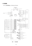
FR-UK Series UPS (10~160KVA)
User’s Manual
? Note?
Please carefully read the user’
s manual before operation for the sake of
understanding correct operation of the instrument. Please keep the manual
handy for future reference.
WARNING
The input and output of the instrument is with danger high
voltages which may endanger the safety of life. Please strictly
follow the operating description is not allowed to remove the
cover of the instrument.
1. Please keep the instrument connect the ground before connecting instrument.
2. The input & output voltage of the instrument is dangerous which will endanger the safety of life.
3. Please do not open the cover of the instrument by yourself in view of danger of shock.
4. Please turn off the mains input switch and the battery breaker for any urgency.
5. There are many kinds of power sources for the instrument, the line bank or the socket may still
have voltage if only the main power is disconnected.
6. Please remove the cable between the battery & instrument before repairing. It’
s necessary to
wait for another 5 minutes for discharging, because of the danger of shock.
7. The wires should be fastened to the terminals. It is prohibited to short the anode and cathode
of battery. It’
s prohibited to touch any two of wire connectors or bare end of connecting wires.
Otherwise, it may lead to damage of battery or personal injury.
8. Please keep the battery and battery group away from the fire and any instrument that may
cause spark to prevent the danger and damage.
9. Please do not open or shatter the battery, the overflow electrolyte is with causticity that may be
harmful to life.
10. Please contact the professional personnel of the local dealer or the special maintenance
station for any trouble-shooting. Random disposal of the trouble is not allowed.
11. This is an A-grade product with electromagnetic compatibility.
12. This equipment must be installed and serviced by qualified personnel.
13. Before you replace the battery of different brand and different type, make sure the charging
voltage is matching with UPS charging voltage due to the different required charging voltage of
different battery, If any doubt, please consult with the manufacturer. Any changes of the
system configuration, structure and composition will influence the performance of UPS, please
consult with the manufacturer in prior before doing any changes.
Contents
1.
System Overview .............................................................................................................1
1.1 Brief Introduction.............................................................................................................1
1.2 Configuration....................................................................................................................1
1.2.1 Basic Configuration ....................................................................................................... 1
1.2.2 Utility Mode ................................................................................................................... 2
1.2.3 Battery Mode................................................................................................................. 2
1.2.4 Bypass Mode................................................................................................................ 2
1.3 System Features and Advantages ...............................................................................3
1.4 Rectifier system...............................................................................................................5
1.5 Inverter system ................................................................................................................6
1.6 Static Switch System ......................................................................................................6
1.7 Maintenance Bypass Switch System...........................................................................6
1.8 the Shape and the Display Panel.................................................................................7
2.
Physical Specification ..................................................................................................17
3.
Installation for UPS .......................................................................................................19
3.1 Selection on location and environment......................................................................19
3.1.1 Location requirement .................................................................................................. 19
3.1.2 Environment Requirement........................................................................................... 20
3.1.3 Power Supply Requirement......................................................................................... 21
3.2 Unpacking .......................................................................................................................21
3.3 The Selection for UPS Input/Output Cable ...............................................................22
3.4 the Connection...............................................................................................................24
3.5 UPS Main Unit Installing ..............................................................................................24
3.6 The Installing of Hot standby System ........................................................................26
3.6.1 The Basic Principle ..................................................................................................... 26
3.6.2 Work Engineering........................................................................................................ 26
3.6.3 Connecting way .......................................................................................................... 27
3.7 Installing Check .............................................................................................................29
3.7.1 Check on Cabinet........................................................................................................ 29
3.7.2 Check on Electric Connection ..................................................................................... 29
3.8 Installation Steps of Three-Phase Series(for example 10~60KVA)...............30
4.
Daily Maintenance .........................................................................................................34
4.1 Before Turning on .........................................................................................................34
4.2 Bootstrap Procedure.....................................................................................................34
4.3 Shut Down......................................................................................................................35
4.4 Operation Procedure for Maintenance Switch: ........................................................35
5.
The Operation Procedure of the LCD Display .......................................................37
5.1 the Buttons .....................................................................................................................37
5.2 Startup/Shut-down Operation......................................................................................37
5.3 Displaying Contents and Related Operation(for example 80KVA) .......................38
6.
The Connection for Communication Port ...............................................................44
6.1 RS232 Communication ................................................................................................44
6.2 RS485 Communication ................................................................................................44
6.3 Dry connection communication...................................................................................44
7.
The selection and maintenance for options...........................................................45
7.1 the Application of Battery.............................................................................................45
7.1.1 Charging /Discharging for battery. ............................................................................... 45
7.1.2 the Selection of Battery............................................................................................... 45
7.1.3 the Notice Project for Battery Use , Maintaining........................................................... 45
7.2 SNMP Card and Software ...........................................................................................46
7.3 UPS Concentrated Monitor..........................................................................................46
8.
Maintenance....................................................................................................................47
8.1 Machinery management...............................................................................................47
8.2 Maintenance Instructions .............................................................................................47
8.2.1 Safety Precautions...................................................................................................... 47
8.2.2 Regular Preventive Maintenance................................................................................. 48
9.
Package, Transportation and storage......................................................................51
9.1 Package..........................................................................................................................51
9.2 Transportation................................................................................................................51
9.3 Storage ...........................................................................................................................51
FR-UK Series UPS ( 10~160KVA) User’
s Manual
1. System Overview
1.1 Brief Introduction
This series is true sine wave on-line UPS with high performance, adopting advanced
technique to protect PC, communication device, electric machine, medical equipment
etc. from disturbing or losing data from power failure. This series product can be use
to resolve all kinds of power problems such as power interruption, voltage fault,
electronic noise, peak, instantaneous voltage fall, lighting, instantaneous voltage
fluctua tion, frequency fluctuation etc.
1.2 Configuration
1.2.1 Basic Configuration
Maintenance Switch
Bypass
LOAD
AC SOURCE
Filter
AC/DC
DC/AC
Utility
Transformer
Battery
Group
Figure 1-1 UPS Basic Configuration
This UPS includes: Input Breaker, Input Filter & Protection Circuit, Rectifier, Inverter,
Static Switch, Bypass Breaker, Isolation Transformer, Output Filter & Battery group etc.
as showed in Figure 1-1. When the utility is normal, AC power goes through filter and
rectifier then change to DC power to inverter for charging the battery, which can be
supply pure power to load at no transfer time.
This system includes four operation modes: utility mode, battery mode, bypass mode
and maintenance bypass mode, showed as following:
-1-
FR-UK Series UPS ( 10~160KVA) User’
s Manual
1.2.2 Utility Mode
As showed in Figure 1-2, at the status of the utility normal, the rectifier changes the
AC power to DC power to inverter and charging the battery. Through the process of
AC power changed to DC power, the inverter can supply more reliability and pure
power to load, as the rectifier can dispel the problems of the portent, noise, unstable
frequency and so on.
Maintenance Switch
Bypass
LOAD
AC SOURCE
Filter
AC/DC
DC/AC
Utility
Transformer
Battery
Group
Figure 1-2 Utility Mode
1.2.3 Battery Mode
As showed in Figure 1-3, when the utility is abnormity, the battery connected to DC
BUS will supply power to inverter, to protecting load from AC power interrupting.
Maintenance Switch
Bypass
LOAD
AC SOURCE
Filter
AC/DC
DC/AC
Utility
Transformer
Battery
Group
Figure 1-3 Battery Mode
1.2.4 Bypass Mode
As showed in Figure 1-4, when the inverter is failure (such as over-temperature, short
current, output voltage abnormity, overload and so on), the inverter should shut off
automatically. If the utility is normal at this moment, the switch will switch to bypass
power to supply power to load.
-2-
FR-UK Series UPS ( 10~160KVA) User’
s Manual
Maintenance Switch
Bypass
LOAD
AC SOURCE
Filter
AC/DC
DC/AC
Utility
Transformer
Battery
Group
Figure 1-4 Bypass Mode
1.2.5 Maintenance Bypass Mode
As showed in Figure 1-5, when you are maintaining or changing the battery, and the
power must not be interrupted, you can shut off the inverter, and turn on the
maintenance breaker, then turn off the rectifier and bypass breaker. At this mode, AC
power goes through maintenance breaker to supply power to load. And at this time,
there may be no any electricity in the UPS inside except the output transformer, and
the maintenance personnel can work without any angst.
Maintenance Switch
Bypass
LOAD
AC SOURCE
Filter
AC/DC
DC/AC
Utility
Transformer
Battery
Group
Figure 1-5 Maintenance Bypass Mode
1.3 System Features and Advantages
C True double conversion on line UPS
Complete isolation at input/output by transformer, and adopting high efficiency IGBT
power module for a real settlement on lighting, voltage between neutral and ground ,
all kinds of pulse and disturbance in power network supply a safe operating
environment for equipment.
-3-
FR-UK Series UPS ( 10~160KVA) User’
s Manual
C Digital DSP Control Technology
The invert control, synchronous phase, input rectifying control, and logic control etc.
are all controlled by DSP, as the control is with high precision, high speed, and high
whole system performance.
C Full function LCD display interface
Large LCD display panel displays the operation status and parameters with rich
display content; and can record the history parameter for maintenance.
C Compatible the load with unbalance 3 phases
Adopting 3 absolutely independent full bridge inverter, the separate control circuit
design, so 3 phase output allow 100% unbalance load. There is not inter affect
between each phase, increasing the inverter reliability.
C Flexible network supervising
This series can realize the intellectual supervising UPS and PC by RS232, SNMP and
independent remote monitor. It is convenient for user power management including 1
to 1 single monitor and 1 to N muti-monitor.
C Manual bypass maintenance design
Design bypass maintenance channel to assure the maintenance on machine without
load power break.
C Reliable EMC features
Passed the authority institution and company test on EMC, including conducting
disturbance, radioactive disturbance, conducting anti-disturbance, radioactive
anti-disturbance, power fault, mass impulsion, static discharging, surge etc. The
predominant EMC features can be applied to high frequency communication,
-4-
FR-UK Series UPS ( 10~160KVA) User’
s Manual
broadcasting audio and video system.
C Wide voltage input range
Strong adaptability for power network can be applied to different voltage range.
C Owns DC startup function
Allow start up by battery without utility power to facility user operation.
C Intellectual battery charging and test
Patented intellectual battery management technique and professional managing
design on battery charging and discharging improve the battery reliability and validity.
The automatic test on battery also reaches above target.
C Redundant design for key circuit
System working power source adopt redundant backup design to improve the system
running reliability.
C Intellectual Fans control
Fans can adjust rotate speed in accordance with the loading status to prolong fans life
and lower noise.
1.4 Rectifier system
The main function of rectifier is to transform AC utility into DC power for inverter. Then
the inverter transforms the DC power into AC power for load, at the same time the
rectifier charges battery group on line.
-5-
FR-UK Series UPS ( 10~160KVA) User’
s Manual
1.5 Inverter system
Inverter: It consists of IGBT module, inductance, capacitor, filter board, control circuit
and protection circuit. It can transform DC power from DC BUS into AC power for load.
Adopting 3 phase inverter independent control technology, the machine compatible 3
phase 100%unbalance load through it takes more cost. The high capacity module with
high performance and well abstraction of heat decreases the fault rate for UPS
inverter.
1.6 Static Switch System
Static switch takes high reliability SCR module. It can switch the load power supply
from bypass to inverter or from inverter to bypass in a short time; It also can switch
invert output to bypass output at inverter fault or other fault instantly; The System
never allows bypass output but to shut down bypass input SCR to prevent the shatter
on user device from the wrong utility supply at abnormal bypass voltage, frequency
and wrong phase order.
1.7 Maintenance Bypass Switch System
For convenient maintaining, UPS set a internal maintenance bypass breaker. It will be
switch off normally, but will be opened only for hot maintenance to keep user load
running without break. To assure maintaining personnel safety, it is necessary to
switch off all UPS internal power during the maintaining. If the maintenance breaker is
opened at normal status, inerter will stop and load power will be switched into bypass
supplying.
-6-
FR-UK Series UPS ( 10~160KVA) User’
s Manual
1.8 the Shape and the Display Panel
500
ON
800
OFF
PHASE
RECTIFIER
INVERTER
BYPASS
BAT .
LOW
OVERLOAD
1180
FAULT
Figure 1-6 External dimension of 10~30KVA
500
O N
800
OFF
PHASE
RECTIFIER
INVERTER
BYPASS
BAT . LOW
OVERLOAD
1180
FAULT
Figure 1-7 External dimension of 40~60KVA
-7-
FR-UK Series UPS ( 10~160KVA) User’
s Manual
Figure 1-8 External dimension of 80~160KVA
-8-
FR-UK Series UPS ( 10~160KVA) User’
s Manual
!
2:1
!
WARNING
Don't operate it except
authorized!
Do operate the UPS
following the user's
manual!
WARNING
Don't operate it except
authorized!
Do operate the UPS
following the user's
manual!
Dismantle Cover Board
SIGNAL
RS232/485
BYPASS
PALL.1
Maintenance
Switch
PALL.2
UPS
RS232/RS485
Communication
Port
Signal
Communication
Port
Paralleled
Communication
Port
Bypass Air
Breaker
Utility Air
Breaker
Output Air
Breaker
OUTPUT
POWER
BYPASS
Battery Air
Breaker
BATTERY
Terminal
N
Grounding
AC INPUT
U
V
AC input
PE
W
BATTERY
+
-
}
Output
PE
W
}
AC OUTPUT
U
V
}
N
Grounding DC input
Figure 1-9 Terminal and breaker of three-phase series( 10~30KVA)
-9-
FR-UK Series UPS ( 10~160KVA) User’
s Manual
!
2:1
!
WARNING
Don't operate it except
authorized!
Do operate the UPS
following the user's
manual!
WARNING
Don't operate it except
authorized!
Do operate the UPS
following the user's
manual!
Dismantle Cover Board
SIGNAL
RS232/485
BYPASS
PALL.1
Maintenance
Switch
RS232/RS485
Communication
Port
Signal
Communication
Port
PALL.2
UPS
Paralleled
Communication
Port
Output Air
Breaker
Bypass Air
Breaker
Utility Air
Breaker
BYPASS
POWER
OUTPUT
BATTERY
Battery Air
Breaker
Terminal
N
Grounding
AC INPUT
U
V
AC input
PE
W
BATTERY
+
-
}
Output
PE
W
}
AC OUTPUT
U
V
}
N
Grounding DC input
Figure 1-10 Terminal and breaker of three-phase series( 40~60KVA)
- 10 -
FR-UK Series UPS ( 10~160KVA) User’
s Manual
PHASE
BYPASS
BATT.
LOAD
FAULT
ON
OUTPUT
OFF
POWER
BYPASS
BATTERY
Figure 1-11 the inside of the door of 60KVA products of this series
- 11 -
FR-UK Series UPS ( 10~160KVA) User’
s Manual
PHASE
BYPASS
BATT.
LOAD
FAULT
ON
OUTPUT
MAINTENANCE
OFF
POWER
BYPASS
BATTERY
Figure 1-12 the inside of the door of 80~160KVA products of this series
- 12 -
FR-UK Series UPS ( 10~160KVA) User’
s Manual
ON
OFF
PHASE
RECTIFIER
Figure 1-13
WELCOME TO USE UPS
MODEL :FR-UK3320
INPUT :398V/50Hz
OUTPUT:398V/50Hz
INVERTER
>>>>>>>>>>==========
FAULT
BYPASS
BAT. LOW
OVERLOAD
display panel structure of three-phase series( 10~60KVA) UPS
(2)
(1)
(3)
ON
OFF
PHASE
RECTIFIER
WELCOME TO USE UPS
MODEL :FR-UK3320
INPUT :398V/50Hz
OUTPUT:398V/50Hz
INVERTER
>>>>>>>>>>==========
FAULT
BYPASS
BAT . LOW
OVERLOAD
(15)
(4)
(5)
(6)
(7)
(8)
(9)
(10)
(11)
(12)
(13)
(14)
Figure 1-14
display panel interface of three-phase series( 10~60KVA) UPS
- 13 -
FR-UK Series UPS ( 10~160KVA) User’
s Manual
Explanation :
(1)、LCD display:Show the running parameter and status of UPS(as voltage、
current、load etc).
(2)、on button
(3)、off button
(4)
、Phase alarm light(red)
:The light will be on when the phase of rectifier input or
bypass input is error.
(5)、Work flo w light of rectifier(green):The light will be on when the rectifier is
normal.
(6)、Work flow light of inverter(green):The light will be on when the inverter is
normal.
(7)、Bypass alarm light(red):The light will be on when there is bypass output.
(8)、Battery low alarm light(red):The light will be on when the battery is low.
(9)、Overload alarm light(red):The light will be on when the output of UPS is
overload.
(10)、Fault alarm light(red):The light will be on when rectifier、inverter or bypass
is error.
(11)、Page up button:Use when lookup display contents of LCD.
(12)、Enter button:Use when lookup display contents of LCD.
(13)、Backup button:Lookup display contents of LCD.
(14)、Page down button:Use when lookup display contents of LCD.
(15)、Page left button:Use when lookup display contents of LCD and turn on LCD
screen light.
- 14 -
FR-UK Series UPS ( 10~160KVA) User’
s Manual
PHASE
BYPASS
A
BATT.
LOAD
FAULT
B
C
U
T
S
R
Q
P
O
N
M
L
D
ON
E
F
G
H
K
OFF
I
J
Figure 1-15 Display panel interface of three-phase series( 80~160KVA) UPS
A: LCD display: Displaying UPS operation status and parameters (i.e. voltage, current,
loading etc).
B: Utility input indicator (Green): Being on at normal utility.
C: Rectifier indicator (Green): Being on at rectifier normal status.
D: Page-up: For looking over LCD displaying contents.
E: Page-left: For looking over LCD displaying contents.
F: Page-down: For looking over LCD displaying contents.
G: On Button: For starting up the UPS with H button.
- 15 -
FR-UK Series UPS ( 10~160KVA) User’
s Manual
H: Enter: For starting up the UPS with G button, and shutting down with I button.
I: Off Button: For shutting down the UPS with H button.
J: Enter: For looking over LCD displaying contents.
K: Turn back: For looking over LCD displaying contents.
L: Battery indicator (Green): Being on at battery supplying status.
M: Inverter indicator (Green): Being on at inverter normal status .
N: Output indicator( Green) : Being on at output voltage normal status.
O: Bypass indicator( Green) : Being on at bypass supply status .
P: Bypass maintenance indicator( Green) : Being on at bypass maintaining status.
Q: Fault alarming indicator( Red) : Being on at rectifier, inverter, or bypass fault.
R: Over load alarming indicator (Red): Being on at UPS output over load.
S: Low battery alarming indicator( Red): Being on at low battery.
T: Bypass alarming indicator( Red) : Being on at bypass output.
U: Phase alarming indicator ( Red) : Being on at wrong phase on rectifier input or
bypass input.
- 16 -
FR-UK Series UPS ( 10~160KVA) User’
s Manual
2.
Physical Specification
Table 2-1 Physical Specification
Input
Model
Specification
FR-UK
3310
FR-UK
3320
FR-UK
3330
Commutation
Three phase commutation
Voltage (Vac)
398±25%
Frequency (Hz)
FR-UK
3350
FR-UK
3360
50
60
50±5%
Phase
3f 4W+GND
Battery voltage (VDC)
12V×29=348V
Rated power (KVA)
10
20
30
Phase
40
3f 4W
Voltage (Vac)
L-N:230
Frequency (Hz)
Output
FR-UK
3340
L-L:398
50±0.2%( battery mode)
Unbalance three phase voltage
=2%,compatible 100%unbalance
stabilization with full load
Wave form
Switch time (ms)
Sine wave, THD<3% at linear load
0
Efficiency
Overload capacity
=90%
125% of rated load last for 15 minutes, 150% of rated load last for 1
minute
Maintenance switch
Maintenance switch with no switch time
Start-up
LCD display
Provided with DC start up function
Input voltage/ Frequency, Output voltage, Battery voltage, Load, DC
current etc.
LED display
Operation status
Alarm function
Overload, AC input abnormal, Low battery, Failure
Others
Communication function
RS232/RS485, dry connection communication signal
Battery test function
Protect function
As showed in 5.3
Battery low voltage, Overload, Over-temperature, Output short circuit,
Output over/low voltage
EMC
GB/T 7260.3-2003
Noise(dB)
<65
Cooling
Fans
Operating Temperature( ℃)
0~40
Relative Humidity
Dimension (W×D×H)(mm)
Weight (Kg)
◆
0~95%,No condensation
500×800×1180
250
300
320
400
Specifications are subject to change without prior notice.
- 17 -
450
460
FR-UK Series UPS ( 10~160KVA) User’
s Manual
Table 2-2 Physical Specification
Model
Input
Specification
FR-UK3380
FR-UK33100
Commutation
Three phase commutation
Voltage (Vac)
398±25%
Frequency (Hz)
FR-UK33160
50±5%
Phase
3f 4W+GND
Battery voltage (VDC)
12V×29=348V
Rated power (KVA)
80
100
Phase
120
160
3f 4W
Voltage (Vac)
L-N:230
Frequency (Hz)
Output
FR-UK33120
L-L:398
50±0.2%( battery mode)
Unbalance three
=2%,compatible 100%unbalance
phase voltage
stabilization with full
load
Wave form
Switch time (ms)
Sine wave, THD<3% at linear load
0
Efficiency
Overload capacity
=90%
125% of rated load last for 15 minutes, 150% of rated load last for 1 minute
Maintenance switch
Maintenance switch with no switch time
Start-up
Provided with DC s tart up function
LCD display
Input voltage/ Frequency, Output voltage, Battery voltage, Load, DC current etc.
LED display
Operation status
Alarm function
Overload, AC input abnormal, Low battery, Failure
Communication
RS232/RS485, dry connection communication signal
function
Others
Battery test function
Protect function
As showed in 5.3
Battery low voltage, Overload, Over-temperature, Output short circuit, Output
over/low voltage
EMC
GB/T 7260.3-2003
Noise(dB)
<65
Cooling
Fans
Operating
0~40
Temperature( ℃)
Relative Humidity
Dimension
(W×D×H)(mm)
Weight (Kg)
◆
0~95%,No condensation
1200×800×1600
840
950
1180
Specifications are subject to change without prior notice.
- 18 -
1300
FR-UK Series UPS ( 10~160KVA) User’
s Manual
3. Installation for UPS
One of the main functions of UPS is to supply safe, pure and stable power to load,
preventing the power source from disturbing fluctuation or break. Normally the life of
UPS is around 5 to 10 years (excludes battery as the validity for battery effected by all
kinds of element such as battery type, using way, environment, humidity and installing
way etc.). It is very important to select a right installing area and environment for
extending UPS’s life .
3.1 Selection on location and environment
3.1.1 Location requirement
Location environment should meet the basic situation for equipment normal
running.
1) Suitable and effective fire protection equipment should be arranged in machinery
room;
2) Machinery room can supply enough AC input voltage and power capacity for
equipment normal running requirement. The utility supplying to UPS should be with
special breaker.
3) Prohibit any flammable and explosive material stocked in machinery room.
4) Finish the preparing of machinery room and ground wires before installation. The
voltage between neutral wire of utility and ground wire in machinery room should
be under 5V;
5) The construction work for machinery room should have finished. Ossified ground
and dry field without dust are necessary.
6) The position for UPS installation should be closed to AC power possibly
7) Ground can burden UPS weight, 4 pieces 90-degree stator can fix UPS. Fixing
UPS on ground with screws to prevent machine remove for earthquake; the feet
installing size is as showed in Figure 3-1 and Figure 3-2、Figure 3-3.
8) UPS machinery room should be locked and only appointed person can have the
key. The machinery room only allows operator or maintaining person enters.
Prohibit other person enter the machinery room.
- 19 -
FR-UK Series UPS ( 10~160KVA) User’
s Manual
M10 expansion bolt
Figure 3-1 Installation of 10-60KVA products of this series
M8 expansion bolt
Figure 3-2 Installation of 80~160KVA products of this series
9) UPS machinery room should be locked and only appointed person can have
the key. The machinery room only allows operator or maintaining person
enters. Prohibit other person enter the machinery room.
3.1.2 Environment Requirement
Environment temperature: 0℃~ +40℃;
Relative humidity: 0%RH~ 95%RH, no condensation;
Cooling: Fan;
Altitude: Meet international standard;
Uprightness: There shall be no shock and the inclination shall no be over 5º;
Pollution grade: Ⅱ;
UPS must be installed in an environment that has enough wind, cool, not high
- 20 -
FR-UK Series UPS ( 10~160KVA) User’
s Manual
humidity and clean air. Operation temperature for recommended is 20~25℃, and
humidity is about 50%.
The place for UPS should be with well ventilation, there should be some space (at
least 1 m) around UPS to facility opening front door and maintaining operation;
there should be some space above UPS (at least 1m) for the upper abstraction of
heat. Recommend there should be some space for the right and left of UPS to
facility UPS daily maintenance.
Prohibit any thing on UPS top to jam the ventilation. And prohibit put UPS in the
place with heat source, the machine with slag result or rusty material, gas source.
Attention:
Prohibit any flammable, explosive and aggressive gas or liquor in the room.
Prohibit operating the installation in the environment with metal electric
conducting dust.
Please do not deploy UPS under fire protection sprayer
3.1.3 Power Supply Requirement
1)
This series requires utility input to be 3 phase 5 lines 398VAC.The capacity of AC utility supply
should be larger than UPS maximum input power;
2) There should be special breaker left for UPS in distributing cabinet or screen in
machinery room to isolate from utility. And the cabinet and screen shall have
better manufactured by professional companies. Input, output breaker and power
distributor cabinet cables are commended in 3.3. The input neutral wire can
connect to UPS without breaker.
3.2 Unpacking
Take down all UPS package and select installing location carefully (as referred
above).
1)
Check following fitting/ options all configured:
Keys, user’s manual
2) Check the specification of UPS all right:
Check if UPS capacity; input voltage and frequency, output voltage and
frequency, phase; battery voltage meet the standard.
- 21 -
FR-UK Series UPS ( 10~160KVA) User’
s Manual
3.3 The Selection for UPS Input/Output Cable
Different capacities UPS need different grade cable. Unconformable cable or breaker
may lead to the fire risky. Please select the size of breaker and cables connecting with
UPS input, output and battery as following. The following only for reference:
1) the choice of breaker
INPUT
MAXIMUM
CURRENT
(A)
BREAKER
(A)
10
230/398V 3F
24
60
20
30
230/398V 3F
230/398V 3F
50
73
60
100
40
50
60
230/398V 3F
230/398V 3F
230/398V 3F
98
122
147
125
150
200
80
100
230/398V 3F
230/398V 3F
172
215
200
250
120
160
230/398V 3F
230/398V 3F
251
344
300
400
POWER
(KVA)
2) the choice of the input cable
MAXIMUM
CURRENT
THE LINE
CABLE
(A)
(mm2)
(mm2)
(mm2)
230/398V 3F
23
10
10
6
20
230/398V 3F
36
16
16
6
30
230/398V 3F
54
16
16
6
40
230/398V 3F
72
25
25
10
50
230/398V 3F
90
35
35
10
60
230/398V 3F
108
35
50
16
80
230/398V 3F
144
50
70
16
100
230/398V 3F
180
70
95
25
120
230/398V 3F
210
95
95
25
160
230/398V 3F
288
95
95
25
POWER
(KVA)
INPUT
10
- 22 -
THE NEUTRAL THE GROUND
CABLE
CABLE
FR-UK Series UPS ( 10~160KVA) User’
s Manual
3) the choice of the output cable
CURRENT
THE LINE
CABLE
THE NEUTRAL
CABLE
THE GROUND
CABLE
(A)
(mm2)
(mm2)
(mm2)
230/398V 3F
15
6
10
6
20
230/398V 3F
29
10
10
6
30
230/398V 3F
46
16
16
6
40
230/398V 3F
58
25
25
10
50
230/398V 3F
72
35
35
10
60
230/398V 3F
91
35
50
10
80
230/398V 3F
116
50
70
16
100
230/398V 3F
133
70
95
16
120
230/398V 3F
160
95
95
25
160
230/398V 3F
232
95
95
25
POWER
(KVA)
OUTPUT
10
4) the DC cable(at the status of 300-410VDC battery voltage)
POWER
(KVA)
MAXIMUM
CURRENT
(A)
CABLE
(mm2)
10
30
16
20
60
25
30
90
35
40
120
50
50
150
50
60
180
70
80
240
70
100
310
95
120
360
95
160
480
95
- 23 -
FR-UK Series UPS ( 10~160KVA) User’
s Manual
3.4 the Connection
N
PE
AC OUTPUT
U
V
W
N
AC INPUT
U
V
PE
BATTERY
+
W
The Neutral wire
of output(N)
The live wire
of output(U)
The live wire
of output(V)
DC input DC input +
Grounding
The live wire
of input(W)
The live wire
of input(V)
The live wire
of input(U)
The Neutral wire
of input(N)
The live wire
of output(W)
Grounding
Figure 3-3 the terminal of 10~60KVA products of this series
OUTPUT N
LA
LB
OUTPUT INPUT LC
N
LA
LB
INPUT
LC
GND
+
-
BATTERY
Figure 3-4 the terminal of 80~160KVA products of this series
3.5 UPS Main Unit Installing
Normal machine system complete machine connecting as showed in Figure 3-5:
- 24 -
FR-UK Series UPS ( 10~160KVA) User’
s Manual
(OUTPUT)
N
AC OUTPUT
U
V
(INPUT)
PE
W
PE
AC INPUT
U
V
N
(BATTERY)
BATTERY
+
W
-
Connect
to battery
cabinet
LOAD
Connect to
main supply
Figure 3-5 the Connection for Single Unit (10~60KVA)
GND
OUTPUT
N
LA
LB
OUTPUT
INPUT
LC
N
LA
LB
INPUT
BATTERY
LC
GND
+
-
BATTERY
to Battery
Cabinet
to
Load
to Utility
Figure 3-6 the Connection for Single Unit (80~160KVA)
Note: the 3 phase line wire as LA, LB, LC showed in figure above, are
corresponding to A phase, B phase, C phase, or R phase, S phase, T phase.
1) Dismantle the breaker cover board in the front of the machine .
2) As showed, connect UPS input, output and battery cables well; pay attention on
the polarity of battery, avoiding wrong polarity connecting.
3) Pay atte ntion on right utility input phase order, or machine cannot start up normally
and the indicator on panel will light on. If the connection is in wrong phase order,
please reconnect in right phase order.
4) Only after assure connection without wrong, startup can be done .
- 25 -
FR-UK Series UPS ( 10~160KVA) User’
s Manual
3.6 The Installing of Hot standby System
3.6.1 The Basic Principle
Change the master machine bypass input connection with utility to with slave machine
UPS output. It is hot backup in series.
Li
Utility
Ni
Figure 3-7
Output
Bypass
input
Bypass
input
Standby
UPS
Main
UPS
Main input
Main input
Lo
Load
No
Principle Diagram of Hot Standby System
At master machine fault, master machine will switch to bypass automatically. At this
moment, slave machine output burden load, and load is still in UPS inverting
protection. So equipment runs well as usual. If master machine stays in bypass and
the slave machine stay in fault, the utility will burden load.
3.6.2 Work Engineering
While working properly, main UPS supplies power to th load and standby UPS idly
runs hot standby system. As show in figure 3-8, thick lines refer to the power passage
of hot standby system
Note: 1. the two units of UPS by hot standby connection mode shall not share
one battery pack, instead, they shall have separate battery packs
2. The AC input(L A,LB,LC,N when three phase) of main UPS, the bypass
input of standby UPS (L,N) and the AC input (L A,LB,LC,N when three
phase) of standby UPS should be from the same utility (L A,L B,LC,N
when three phase), at the same time, the order of phase must be
consistent. When it is three phase the bypass input (L,N) should be
connected to utility(L2,N).
- 26 -
FR-UK Series UPS ( 10~160KVA) User’
s Manual
Figure 3-8 Power Flow Chart of UPS Hot Standby in Normal Condition
In case of main UPS failure, the main UPS is switched to bypass status and standby
UPS supplies power to the load. As show in figure 3-9, the thick lines refer to the
power passage of hot standby system in case of main UPS failure.
Figure 3-9 Power Flow Chart of Hot Standby System in case of Main UPS Failure
3.6.3 Connecting way
3.6.3.1 Connecting Steps
1) Dismantle the breaker cover board in the front of the machine .
2) Dismantle the short wire connecting between bypass input breaker and utility input
breaker of main unit, and dismantle the neutral of input. Connect the 3-phase line
- 27 -
FR-UK Series UPS ( 10~160KVA) User’
s Manual
wires of standby unit to the bypass input breaker in order; the output neutral of
standby unit to the input neutral of main unit.
3) Connect the utility input of main unit to the utility input of standby unit.
Attention: Utility input phase order should be right, or machine cannot start up
normally and the phase order indicator on panel will light on. The wrong phase
order connection should be corrected.
4) Other connection is the same as the connection of single unit, as showed in figure
3-10、figure 3-11.
5) Only after assure the right connection, startup can be done.
3.6.3.2 Connecting Way
The connection of the hot standby system is as showed in figure 3-10、figure 3-11:
Main Machine
U
N
U
V
OUTPUT
LOAD
W
N
U
V
INPUT
W
PE
Slave Machine
Bypass breaker of
main machine
V
W
+
-
BATTERY
N
U
V
OUTPUT
W
N
U
V
INPUT
W
PE
Connect to battery cabinet
of Main UPS
+
-
BATTERY
Connect to battery
cabinet of Slave
UPS
Connect to
Mains supply Power
Figure 3-10 Connection of the Hot Standby System(10~60KVA)
- 28 -
FR-UK Series UPS ( 10~160KVA) User’
s Manual
GND
OUTPUT
INPUT
BATTERY
LA
N
LA
LB
OUTPUT
LC
N
LA
LB
INPUT
LB
GND
OUTPUT
N
LA
LB
OUTPUT
to Battery
Cabinet of the
Main Unit
to Load
INPUT
BATTERY
LC
+
-
BATTERY
LC
GND
the Breaker for
Maintenance of the
Main Unit
LC
N
LA
LB
INPUT
+
-
BATTERY
LC
to Utility
GND
to the Battery
Cabinet of the
Standby Unit
Figure 3-11 Connection of the Hot Standby System(80~160KVA)
Note: the 3 phase line wire as LA, LB, LC showed in figure above, are
corresponding to A phase, B phase, C phase, or R phase, S phase, T phase.
3.7 Installing Check
3.7.1 Check on Cabinet
Complete the assembly on cabinet then check the following item for cabinet installing:
1) Steady and elegant;
2) Uprightness angle less than 5°;
3) Cabinet panel should be on the same horizontal without roughness;
4) Check the tightness of all screws to find whether be lack of washer, spring washer,
or fixing in reverse.
5) Check any redundant material left on cabinet. If so, please clean them.
6) Check any scratch, damage or paint-off on cabinet.
7) Check the clean of cabinet, clean dust and dirt.
3.7.2 Check on Electric Connection
After the electric connection, please check the electric connection as following items:
1) Input and power distribution examination: whether AC cable meet standard, the
loose of the internal cable in cabinet, full safety mark for AC distributing cell;
2) The examination on connection, series no, line order, polarity for output and
battery, stability of cable connection. Recheck the battery connecting polarity and
- 29 -
FR-UK Series UPS ( 10~160KVA) User’
s Manual
order.
3) Check the harness to be elegant, the cable banding to meet work art regulation.
4) Make sure the installation, harness whether to be facility the system upgrade,
extending and maintenance.
3.8 Installation Steps of Three-Phase Series(for example 10~
60KVA)
Remove the UPS from bracket to ground for installation. The following is the
installation instruction of Three-Phase Series(10~60KVA).
The external structure of three-phase series(10~60KVA)is as followed after
unpacking:
1.
Figure 3-12 Installation Step 1
2.
Loose the 4 carrying bolts M16×65 front and back of mainframe and the 6 hex bolts
M12×40 between horses and mainframe6,make the wheels of mainframe contact
with bracket.
- 30 -
FR-UK Series UPS ( 10~160KVA) User’
s Manual
M12×40 hex bolts
M16×65 hex bolts
Figure 3-13 Installation Step 2
3. Unlock the loose ground horse and binding hex bolts M12×40 locked on
mainframe,then unlock the binding hex bolts M12×80 fixed ground horse and
bracket,and remove ground horse.
M12×80 hex bolts
M12×40 hex bolts
Ground horse
Figure 3-14 Installation Step 3
- 31 -
FR-UK Series UPS ( 10~160KVA) User’
s Manual
4. Mainframe is pushed from bracket to ground through inclined bracket.
Figure 3-15 Installation Step 4
5. Choose and layout installation site,drive 4 expansion bolt M10 into ground. Require
space:506mm×525mm,the exposed height of expansion bolt should be controlled
within 50mm.
M10 expansion bolt
Figure 3-16 Installation Step 5
6. Mount “T”type ground horse,cover gasketF10、spring gasketF10 and nut M10,
lock tight.
- 32 -
FR-UK Series UPS ( 10~160KVA) User’
s Manual
Gasket F10
Spring gasket F10
Nut M10
Ground horse
Figure 3-17 Installation Step 6
7. Mainframe is pushed between two-ground horses,re-heighten 4 loose carrying
bolts M16×65,lock tight between mainframe and horses with 6 hex bolts M12×40.
Figure 3-18 Installation Step 7
- 33 -
FR-UK Series UPS ( 10~160KVA) User’
s Manual
4. Daily Maintenance
4.1 Before Turning on
Make sure all cables are in right connection and following items all right before
startup.
1) If the input voltage is in the rated input voltage range.
2) If input frequency is in the rated input frequency range.
3) If all loads connected to output terminal is switch off.
4) If all breakers and battery is switch off.
Please operate the UPS following the procedure referred follow.
4.2 Bootstrap Procedure
The bootstrap should follow the steps as:
1) Turn on bypass power breaker(BYPASS):
Power board begins to work, LCD on the panel initiate displaying. Then low
battery indicator will light on and buzzer will beep continuously.
2) Turn on rectifier breaker(POWER):
Supposing the right input power initiate rectifier automatically, the rectifier
indicator (AC/DC) on panel will light on. DC voltage will be established
completely after 20s time prolong, and Battery low indicator and buzzer alarming
will terminate.
3) Turn on battery breaker(BATTERY):
Turn on battery breaker, rectifier start to charge battery.
4) Press the inverter button on panel:
This series UPS start up or shut down operation adapts “double buttons combination
operation”to prevent the wrong operating.
At startup, just press
(for 10~60KVA) and
(for 80~160KVA) on the
panel more than 1 second , DC/AC indicator on will light on, invert output indicator will
light on. The equipment will come into normal invert output after 30 seconds. The
first-time starting of this series does not allow to output bypass supply, so it is normal
for first-time starting without bypass output voltage.
5) Turn on load:
Usually one should wait till the UPS is running smoothly before tur ning on the loaded
equipment, first turning on the higher power equipment, then the lower power
- 34 -
FR-UK Series UPS ( 10~160KVA) User’
s Manual
equipment.
4.3 Shut Down
Shut down the UPS following the operation as:
1) Turn off the inverter:
Press the buttons
(for 10~60KVA) and
(for 80~160KVA) on
panel at the same time to turn off inverter. At this moment the static breaker will
transfer the power supply for load automatically from inverter to bypass to prevent
output voltage break.
2) Turn off battery breaker(BATTERY):
If want to tur n off all UPS power, please continue to switch off battery breaker,
so rectifier only stock power in DC BUS.
3) Turn off rectifier input breaker (POWER):
Turn off rectifier breaker, the rectifier can not establish DC power from AC utility
to DC BUS,DC BUS will discharge power slowly, it will take DC BUS about 2
minutes later.
4) Turn off bypass input breaker(BYPASS):
Before switch off bypass input breaker,you have to assure output load nonuse,
or there will be no power output from output terminal to terminate user
equipment power at breaking bypass input breaker.
5) The shut down procedure will be finished after the LCD display and LED
indicators light off.
4.4 Operation Procedure for Maintenance Switch:
Press the buttons on panel
(for 10~60KVA) and
(for 80~160KVA)
at the same time to turn off inverter.
1) Turn off rectifier breaker (POWER) and battery breaker (BATTERY) after the
bypass indicator on panel lights on.
- 35 -
FR-UK Series UPS ( 10~160KVA) User’
s Manual
2) Position maintenance switch/ maintenance breaker to “BYPASS”/”ON”position,
turn off bypass power breaker (BYPASS) after bypass maintenance indicator
(BYPASS) on panel lights on. Open the panel to switch main board SW1-3 shift
switch to ON (or take out the connection for main control board CN14). After all
indicators on panel light off, switch main board SW1-3 shift switch to OFF (or
resume the connection for main board CN14); then it can be maintained.
3) After the maintenance finished, turn on bypass power breaker (BYPASS). Switch
maintenance switch to “UPS”/ “ON”position after the bypass indicator on panel
(BYPASS) lights on; bypass power output for UPS is initiating.
4) Then begin to do the operation as the 4 th daily operating procedure.
- 36 -
FR-UK Series UPS ( 10~160KVA) User’
s Manual
5. The Operation Procedure of the LCD Display
The LCD display can display all running status and parameters of UPS. User can
preset some UPS parameters and control UPS by operating interface. Full LCD
screen can display 5 lines of characters. More characters can be displayed by turning
up/down pages rolling. Elegant and simple operation buttons facility user operating.
5.1 the Buttons
There are 5 buttons for this series whose function is as showed following :
This button means “upward roll / parameter setting +”used for
upward rolling at multi-lines of characters displaying / adding
parameter value at Parameter setting.
This button means “downward roll / parameter setting— ”used for
downward rolling at multi-lines of characters displaying / decreasing
parameter value at Parameter setting.
This button means “parameter setting”used for selecting switch
when many options in the same display page.
This button means “enter”used for confirming the selected option
with mark“>”or set parameter confirm.
This button means “turn back to upper page”used for turning back
to upper menu or direct come back without parameter input.
5.2 Startup/Shut-down Operation
This Series UPS On/Off keys for 10~60KVA.:
Power on: Push
key about 1S
Power off: Push
key about 1S.
.
This series UPS start up or shut down operation adapts “double buttons combination
operation”to prevent the wrong operating for 80~160KVA.
- 37 -
FR-UK Series UPS ( 10~160KVA) User’
s Manual
They position on the panel as:
Startup ---- press
for more than 1 second.
Shut down ---- press
for more than 1 second.
5.3 Displaying Contents and Related Operation(for example 80KVA)
1) Shut off UPS bypass breaker.
WELCOME TO USE UPS Model : FR-UK3380 Input : 398V/50Hz Output : 398V/50Hz SYSTEM CHECKING,PLEASE WAIT... >>>>>>>>>>>>>>>>>>============== It will return to normal page after 10 seconds. It also can be realized by pressing
button to return normal page directly.
2) The output parameter will be displayed in normal page for this series. It means
that LCD display will switch into output parameter displaying under power on
without button input or no button input after 1 minute.
UPS 80KVA Output R S T Vl-n: 230V 230V 230V Load: 0% 0% 0% UPS Status: Normal 29-03-2006 08:00:00 In this display page, user can turn into function menu by pressing the
button. Other buttons are negative.
3) Single menu page:
This page designed for the displaying all menu options of UPS, “>”mark means the
present selected option.
- 38 -
FR-UK Series UPS ( 10~160KVA) User’
s Manual
UPS 80KVA Rectifier data Bypass data Output data Battery data Working status Buzzer control ▼ There are other menu options as following:
BATTERY TEST
LANGUAGE
DATE&TIME SETTING
MANUFACTURER INFO
HISTORICAL EVENT
Press
to position mark “>”at selected option in menu.
The mark at right up and right down means there are still some contents in screen can
be displayed by up or down rolling page.
Press
button into the option with“>”mark.
Press
button back to normal output parameter normal page.
4) Rectifier parameter page:
This page displays 3 phase input voltage, frequency of UPS rectifier and rectifier DC
output voltage.
UPS 80KVA Rectifier data R S T Vl-n: 230V 230V 230V Frequency : 50.0Hz Rectifier Output: 390V Press
button back to upper menu index, other buttons are negative.
5) Bypass parameter page:
This page display UPS bypass 3 phase voltage and frequency.
- 39 -
FR-UK Series UPS ( 10~160KVA) User’
s Manual
UPS 80KVA Bypass data R S T Vl-n: 230V 230V 230V Frequency: 50.0Hz Press
button back to upper menu index, other buttons are negative.
6) Output parameter page:
This page displays UPS three phases output voltage and load percentage for each
phase.
UPS 80KVA Output data R S T Vl-n: 230V 230V 230V LOAD: 20% 20% 20% Frequency: 50Hz Press
button back to upper menu index. Other buttons are negative.
7) Battery parameter page:
This page contains UPS battery voltage and charging (discharging) current. It will
display charging current at UPS rectifier normal status; display discharging current at
UPS inverting status.
UPS 80KVA Battery data Battery voltage : 384V Charge current: 5A Press
button back to upper menu index, other buttons are negative.
8) Running status page:
This page contains all UPS work status.
- 40 -
FR-UK Series UPS ( 10~160KVA) User’
s Manual
UPS 80KVA Working status
Phase
: Normal
Bypass Status : Normal
Rectifier Status : Normal
Battery Status : Normal
Inverter Status: Normal
▼
There are other two lines marked at right down of screen.
OUTPUT: NORMAL
LOAD STATUS:
NORMAL
TEMPERATURE:
Press
Press
26( C)
buttons to do rolling browse.
button back to upper menu index. Other buttons are negative.
9) Buzzer mute control page:
This series UPS supply UPS mute control. User can shut down buzzer intermission
beeping alarm when UPS stay in inverting without input utility. Buzzer will initiate
alarming automatically and be out of control from the shield at UPS abnormal status.
UPS 80KVA Buzzer control Current Status : On Buzzer On Buzzer Off Press
Press
Press
buttons to select the options for On/Off.
button to confirm the selected status.
button back to upper menu index. Other buttons are negative.
10) Battery test control page:
This series UPS supply battery test function, the principle is to discharge UPS battery
in a short time to test battery validity by lowering DC output voltage under long time
- 41 -
FR-UK Series UPS ( 10~160KVA) User’
s Manual
utility input status.
UPS 80KVA Battery Test Current Status : Close Abort Test General Test Deep Test Press
button to confirm the selected status.
Press
button to back to upper menu index. Other buttons are negative.
11) UPS internal time adjusting:
This series UPS with internal timer chip can displays present time. User can adjust
time by this page.
UPS 80KVA Time Setting Date: 2006 - 03 - 29 Time: 08 : 00 : 00 Press
button to move the mark among the position of year, month, date,
hour, minute, second.
Press
button to add or reduce time parameter.
Press
button to confirm the adjusted time meter and input UPS internal
timer chip.
Press
button to back to upper menu index.
12) Manufacturer:
This page display UPS manufacturer information, mode name, version and equipment
I D address No.
- 42 -
FR-UK Series UPS ( 10~160KVA) User’
s Manual
I D address NO supply address coding information to communication data port at UPS
taking RS485 multi-machines supervising. It can be set with a series codes in UPS.
So we recommend not to change this meter normally.
UPS 80KVA Manufacturer info Manufacturer: UPS Model : FR-UK33×0 Hardware : Version 2.0 Control Soft: Version 2.0 UPS ID : 01 Press
button back to upper menu index. Other buttons are negative.
13) History record page:
This page supplies some important history parameter, the time for it and related
display of UPS. They are the basic reference data for analysis on local network and
abnormal situation.
UPS 80KVA Historical Event AC Fail Count:0 Latest Poweroff: 2005-01-01 18:00 Current Poweron: 2005-01-02 18:00 Press
buttons to do rolling browse
Press
Press
button back to upper menu index. Other buttons are negative.
+
buttons more than 10 seconds to clean the history record
in UPS memory to facility the fault analysis for maintenance . So it is recommended
not to clean history data frequently.
- 43 -
FR-UK Series UPS ( 10~160KVA) User’
s Manual
6. The Connection for Communication Port
6.1 RS232 Communication
There is a RS232 communication port on panel display control board. It is optional for
UPS supervising software, SNMP card, supporting close communication for UPS
( generally no more than 10M) ; Realizing the remote control on UPS input voltage,
frequency, and output voltage, frequency, loading etc parameters. The remote on/off
machine is allowed.
6.2 RS485 Communication
There is a RS485 communication port on panel display control board, it can support
remote communication. Realizing the remote control on UPS input voltage, frequency,
output voltage, frequency, loading etc parameters. The remote on/off machine is
allowed.
6.3 Dry connection communication
There are two dry connection communication ports on the panel display control board.
They are for low battery and utility fault ; they are close for low battery , utility fault.
- 44 -
FR-UK Series UPS ( 10~160KVA) User’
s Manual
7. The selection and maintenance for options
7.1 the Application of Battery
7.1.1 Charging /Discharging for battery.
Battery bank is an important apparatus to assure the uninterrupted power supply for
UPS. Battery bank connects with the battery branch circuit of UPS system. Power
system will do float charging or balance charging on battery bank at utility normal
status; the battery supply user equipment by inverting at utility fault.
7.1.2 the Selection of Battery
1) The selection of battery bank capacity. It depends on two factors of the needed
current for load equipment in power system and the respected battery discharging
time. Supposing discharging current of the battery bank in power system is 80A,
the respected battery bank power supply time at AC break is 10h. So the system
require battery capacity= battery discharging current× The power supplying time at
AC break=800Ah, there is an added redundancy on the theory battery capacity .
That is the practical capacity of battery. The principle of battery selection should
be a certain higher capacity than theory capacity. The redundant value should be
in 20% of capacity of load.
2) Prohibit different capacity batteries be used in series and different voltage battery
be used in parallel mode.
Please do not connect different capacity battery bank in parallel mode(
the different
battery internal resistance will affect charging current procedure to lead different
capacity battery without full charging. That will result in two different battery bank: one
gets over charge , another one gets low charging;
And there will be battery bank
mutual discharge at discharging procedure) .
7.1.3 the Notice Project for Battery Use , Maintaining
1) Muti-banks of battery in parallel mode, the total capacity of battery bank equals to
the sum of all batteries capacity.
- 45 -
FR-UK Series UPS ( 10~160KVA) User’
s Manual
2) The using environment temperature is in 0℃~40℃,the validity of battery and
battery temperature are in inverse proportion, so there should arrange abstraction
of heat on the design for high temperature battery application to prevent the sharp
increasing of battery temperature. (
When battery bank under increasing
temperature, the polarity board will be corrupted badly by vitriol. That will shorten
validity of battery.)If it is possible, please fix air conditioning in machinery room to
prolong battery validity.
3) After completion of power system fixing, charge the first used battery or longtime
unused battery before their application;Battery will loss the capacity in stock
slowly for longtime self discharging. Without full charging, the battery can not
reach accordant performance.
Check all parts of battery and fasten status connection once to prevent accident after
a certain period. Tightening work is also necessary.
7.2 SNMP Card and Software
SNMP card will be fixed in UPS internal SNMP card slot or outlay to realizing network
remote management on UPS. Hot change design realizes fast and facility direct
change and maintenance. User can supervise UPS by IE etc browser UPS. Operating
illustration follow the user manual of net adapter.
7.3 UPS Concentrated Monitor
Background monitoring software-concentrating monitor can realize the background
supervising over UPS and remote On/Off machine. Operation illustration follow
concentrating monitor user manual.
- 46 -
FR-UK Series UPS ( 10~160KVA) User’
s Manual
8. Maintenance
8.1 Machinery management
The management of machinery room includes environment and safety management,
equipment management.
1) Basic target for environment safety management: Make sure environment
temperature, related humidity, brilliance, Static disturbing, noise, Strong EMC
disturbing to meet standard requirement to assure the stability , reliability , security
of power equipment. All for the normal power supplying for load equipment.
2) Basic demand on equipment management: ensure the machinery performance o f
equipment well, the electric performance of equipment meet the standard,
reliability and stability of equipment, and intactness of equipment related technical
reference and original record.
8.2 Maintenance Instructions
Correct maintenance, including preventive and remedy maintenance, is key to optimal
operation of UPS and will prolong the equipment’s life span. Preventive maintenance
includes some frequently executed procedures which are for the prevention of system
faults and maximization of system efficiency; remedy maintenance includes
trouble-shooting of the system for effective maintenance.
8.2.1 Safety Precautions
In order to carry out system maintenance safely and successfully, the relevant safety
precautions must be carried out, essential tools and testing equipment shall be used
and qualified maintenance staff shall participate. The following safe operation
procedures shall be observed at any time:
1.
Bear in mind that there is dangerous voltage in UPS even if it is not running.
2.
Make sure that the operation and maintenance staff of UPS is familiar with the equipment
and this manual.
3.
Do not wear gold or silver ornaments like rings and watches, etc during operation of UPS.
- 47 -
FR-UK Series UPS ( 10~160KVA) User’
s Manual
4.
Do not take for granted the safe operation procedures. If you have any questions, please
consult those who are familiar with the equipment.
5.
Look out for the dangerous voltage in UPS. Before maintenance and adjustment, use a
voltage meter to ensure that the power supply is switched off and it is safe for operation.
8.2.2 Regular Preventive Maintenance
The following are the steps of preventive maintenance which, after execution, will
increase the efficiency and reliability of UPS system.
1.
Maintain a clean environment to avoid dust or chemical pollution to the UPS.
2.
Wiring
Check once half a year if the input and output terminals have good contact.
3.
Check regularly the operation of draught fans to prevent choking of draught. They shall be
replaced in case of damage.
4.
Check regularly battery voltage and UPS working status.
Following are simple settlement on fault. The fault should be under the control from
products agent, eligible and professional engineer or technician of factory. Normally
please avoid taking apart at will to prevent the risky of electric shock.
Abnormal
phenomena
Fault diagnosing and checking appoints
Rectifier utility input breaker close, the
(1)AC/Dc indicator
off, FAULT
indicator on.
(2)Panel phase
order light on,
buzzer
alarming.
front panel INPUT indicator, AC/Dc
light off, FAULT light on.
Settlement
Open rectifier utility
input breaker.
The rectifier input voltage abnormal,
Connecting the normal
AC/DC light off, FAULT light on.
voltage for rectifier.
Fault phase for AC input, LCD display
the wrong message, the front panel
phase light on( PHASE) . Buzzer
alarming.
- 48 -
Change the phase order
of rectifier utility input
lines, normally
exchange two phases
of LA? LB? LC phase.
FR-UK Series UPS ( 10~160KVA) User’
s Manual
(3)Inverter output
does not
work, buzzer
alarm.
(4)UPS paralyzing
and supplying 0
output at utility
fault.
Rectifier does not start up. Buzzer
long alarms and low battery light
on.
After the completion of
the rectifier slow
startup, the buzzer
alarming will be
terminated.
Shows output over load. The front
Reduce UPS power
panel OVERLOAD light on.
load.
Battery breaker close.
All UPS breakers stay in close.
(5) LCD or LED off
(6) Fan stop
rotating
UPS front panel.
Abnormal LB phase output voltage,
Charged by professional
fans fault
maintaining technician.
Over temperature of inverter heat
Remove short circuit
point, shut down UPS
inverter, restart inverter.
sink.
Reduce load, or balance
the loads;
The fuse on inverter fused, or IGBT
module abnormal
Change fuse or IGBT
module
Input utility fault, battery in low battery
protection for discharging.
(9) UPS can not
switch inverting
supply to bypass
supply at off
machine.
Open one breaker on
Charged by professional
maintaini ng technician.
( including load short circuit).
(8) Panel
OVERLOAD light
on
breaker
Power board fault
Short circuit at output terminal
(7)Panel FAULT
light on, buzzer
long alarming
Switch on battery
Restart at utility resume.
UPS output overload.
Reduce load.
Make sure whether bypass power
Check bypass power
input voltage and frequency normal.
voltage, frequency.
Fault on bypass/invert SCR driving
Charged by professional
board
maintaining technician.
- 49 -
FR-UK Series UPS ( 10~160KVA) User’
s Manual
(10) UPS can not
switch from
bypass power
supplying to
invert power
supplying at
bootstrap.
(11)Abnormal
communication.
Inverter fault.
Charged by professional
maintaining technician.
Fault on bypass/invert SCR driving
Charged by professional
board.
maintaining technician.
Wrong connection of communication
Reconnect with right
cable
port.
Communication Software not installed
unsuccessfully.
Install software correctly
Wrong setting for PC communication
Correct communication
interface.
port set.
Excludes above problem, still have no
normal communication.
- 50 -
Charged by professional
maintaining technician.
FR-UK Series UPS ( 10~160KVA) User’
s Manual
9. Package, Transportation and storage
9.1 Package
The main unit of this UPS is firstly packaged in carton, and then in wooden case for
more protective. There are some signs on the carton, such as model, volume, date
etc.
9.2 Transportation
It should strictly conform to the care signs during transportation, and place the UPS
according to the care signs, to avoid the shake to the UPS. It can’t put the equipment
on the open vehicle and cabin, and should be put together with flammable articles. It is
prohibited to put the equipment in the open air in the midway, and should avoid the
drench of the rain, snow or other wet goods, also machinery damage.
9.3 Storage
Place the equipment according to the care signs. It should part from ground for 20cm,
part from wall, hot source, cold source, windows or air entrance for 50cm.
Environment temperature for storage is 0~ 40℃, relative humidity is 20%~ 80%, the
stock should not have any baleful gas, flammable and corrosive chemistry, have not
strong shake, strike and magnetic field. The storage period in this condition is for six
months, over six months, the equipment should be checked, and charged the battery
every three months.
- 51 -