1
Three-Phase FR-UK Series UPS
(10-160 kVA)
User’s Manual
Three-Phase UPS FR-UK Series (10~160 kVA) User’s Manual
【Note】
】
Please carefully read the user’s manual before operation for the sake of
understanding correct operation of the equipment. Please keep the manual
handy for reference.
WARNING
The input and output of the instrument is with danger high
voltages which may endanger the safety of life. Please strictly
follow the operating description is not allowed to remove the
cover of the instrument.
1. Please connect protective earth before power supply cables.
2. The input & output voltage of the UPS is dangerous which will endanger the safety.
3. Dangerous voltages are present inside the unit. Please do not open the cover of the UPS.
4. Please turn off the mains input switch and the battery switch for any urgency.
5. There are many kinds of power sources in the equipment, the line bank or the socket may still
have dangerous voltage even if the main power is disconnected.
6. Please remove the cable between the battery & UPS before repairing. It’s necessary to wait for
another 5 minutes for discharging, because of the dangerous voltages.
7. The wires should be fastened to the terminals. It is prohibited to short the anode and cathode
of battery. It’s prohibited to touch any two of wire connectors or bare end of connecting wires.
Otherwise, it may lead to damage of battery or personal injury.
8. Please keep the battery away from the fire and all the equipment that may cause spark to
prevent the danger and damage.
9. Please do not open or shatter the battery, the overflow electrolyte is with causticity that may be
harmful to life.
10. Please contact the professional personnel of the local dealer or the special maintenance
station for any trouble-shooting. Random disposal of the trouble is not allowed.
11. This is an A-grade product with electromagnetic compatibility.
12. This equipment must be installed and serviced by qualified personnel.
13. Before you replace the battery of different brand and different type, make sure the charging
voltage is matching with UPS charging voltage due to the different required charging voltage of
different battery, If any doubt, please consult with the manufacturer. Any changes of the
system configuration, structure and composition will influence the performance of UPS, please
consult with the manufacturer in prior before doing any changes.
14. Before usage, confirm that the temperature of the instrument has dropped into the normal run
range. It is recommended still placement for 24 hours in the normal temperature range before
startup.
Product Standard:
:Q/ZZKJ001-2008
Three-Phase UPS FR-UK Series (10~160 kVA) User’s Manual
INDEX
1. Overview ........................................................................................................................................ 1
1.1 Brief Introduction ................................................................................................................... 1
1.2 System Features and Advantages ........................................................................................ 1
1.3 Configuration ......................................................................................................................... 3
1.3.1 Basic Configuration..................................................................................................... 3
1.3.2 Operation Modes ........................................................................................................ 3
1.3.2.1 Utility Mode .............................................................................................................. 3
1.3.2.2 Battery Mode............................................................................................................ 4
1.3.2.3 Bypass Mode ........................................................................................................... 4
1.3.2.4 Maintenance bypass mode...................................................................................... 5
1.4 Hot standby system............................................................................................................... 5
1.4.1 Basic Principle ............................................................................................................ 5
1.4.2 Working Engineering .................................................................................................. 5
1.5 Parallel System ..................................................................................................................... 7
1.5.1 Basic Principle ............................................................................................................ 7
1.5.2 Working Engineering .................................................................................................. 7
1.6 The Choices of Parallel System and Series System ............................................................ 9
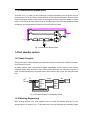
1.7 Principle Machine Structure .................................................................................................. 9
1.7.1 Display Structure and Display Interface of Three-Phase(10~30 kVA)UPS .......... 9
1.7.2 Display Structure and Display Interface of Three-Phase(40~160 kVA)UPS ...... 11
1.7.3 Outlook of three-phase UPS FR-UK series(10~30 kVA)..................................... 12
1.7.4 Outlook of three-phase UPS FR-UK series(40~60 kVA)..................................... 13
1.7.5 Outlook of three-phase UPS FR-UK series(80~160 kVA) .................................. 14
2. Physical Specification ............................................................................................................... 15
3. Installation for UPS .................................................................................................................... 19
3.1 Installation instruction.......................................................................................................... 19
3.2 Installation Steps ................................................................................................................. 19
3.3 Preparing for Installation ..................................................................................................... 20
3.3.1 Check the installation site ......................................................................................... 20
3.3.2 Unpacking and Inspection ........................................................................................ 24
3.4 Equipment Installation ......................................................................................................... 25
3.4.1 Installation Notes ...................................................................................................... 25
3.5 Check the main input .......................................................................................................... 25
3.6 Installation of UPS............................................................................................................... 25
3.6.1 Installation steps of three-phase UPS FR-UK Series (10~30 kVA) ........................ 25
3.6.2 Installation steps of three-phase UPS FR-UK Series (40~160 kVA) ...................... 27
3.6.3 The structure of base plate of three-phase UPS FR-UK Series (10~160 kVA) ....... 29
3.7 Battery Cabinet Installation ................................................................................................. 30
3.7.1 Important safety rules ............................................................................................... 30
3.7.2 Installation step ......................................................................................................... 30
3.8 (Parallel) System installation............................................................................................... 31
3.9 Electrical connection ........................................................................................................... 31
3.9.1 Wire modes of single UPS ........................................................................................ 31
Three-Phase UPS FR-UK Series (10~160 kVA) User’s Manual
3.9.2 Method of Connection for the two units of UPS by Hot Standby System. ............... 33
3.9.3 Connecting way of Parallel System .......................................................................... 37
3.10 System Inspection and testing .......................................................................................... 40
3.10.1 Check electrical connections .................................................................................. 40
3.10.2 UPS testing ............................................................................................................. 40
3.10.3 Connect with the load ............................................................................................. 40
4. Operation..................................................................................................................................... 41
4.1 Notes of using UPS ............................................................................................................. 41
4.2 UPS single unit operation process...................................................................................... 41
4.3 Operation instruction ........................................................................................................... 41
4.3.1 Inspection before power on ...................................................................................... 41
4.3.2 Single Unit Bootstrap procedure of Three-phase UPS (10~160 kVA) ..................... 42
4.3.3 Start the load............................................................................................................. 43
4.3.4 Turn Off UPS ............................................................................................................ 43
4.4 Operating procedure of Parallel System ............................................................................. 44
4.4.1 Parallel System Start-up ........................................................................................... 44
4.4.2 Parallel System Shut Down ...................................................................................... 45
4.4.3 Online shutdown Parallel System ............................................................................. 45
4.4.4 Online start-up Parallel System ................................................................................ 45
4.4.5 Redundancy and Expansion of Parallel System ...................................................... 45
4.5 Manual bypass Maintenance Operation Process ............................................................... 46
5 Maintenance Instructions ........................................................................................................... 47
5.1 Maintenance Guide ............................................................................................................. 47
5.1.1 Safety Precautions.................................................................................................... 47
5.1.2 Regular Maintenance................................................................................................ 47
5.2 Daily maintenance of battery .............................................................................................. 47
5.3 Attentions when replace batter............................................................................................ 48
5.4 Troubleshooting................................................................................................................... 48
5.4.1 FAQ ........................................................................................................................... 48
5.4.2 Troubleshooting for single system and parallel system ........................................... 49
6. Panel LCD Display Operation Procedure ................................................................................ 51
6.1 Push Key Function Illustration ............................................................................................ 51
6.2 On/Off Operation ................................................................................................................. 51
6.2.1 On/Off Operation of Three-phase (10~30 kVA) UPS ............................................... 51
6.2.2 On/Off Operation of Three-phase (40~160 kVA) UPS ............................................. 51
6.3 Display and Related Operation ........................................................................................... 52
7 Communication Interface Connection Way .............................................................................. 62
7.1 RS232 Communication ....................................................................................................... 62
7.2 RS485 Communication ....................................................................................................... 62
7.3 Dry Contact Communication ............................................................................................... 62
Appendix A ...................................................................................................................................... 64
Package, Transportation and Storage.......................................................................................... 64
A.1 Package .............................................................................................................................. 64
A.2 Transportation..................................................................................................................... 64
Three-Phase UPS FR-UK Series (10~160 kVA) User’s Manual
A.3 Storage ............................................................................................................................... 64
Appendix B ...................................................................................................................................... 65
Toxic and Hazardous Substances or Elements Table ................................................................ 65
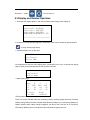
1. Overview
1.1 Brief Introduction
This series is true sine wave on-line UPS with high performance, adopting advanced technique to
protect PC, communication device, electric machine, medical equipment etc. from disturbing or
losing data from power failure. This series product can be use to resolve all kinds of power
problems such as power interruption, voltage fault, electronic noise, peak, instantaneous voltage
fall, lighting, instantaneous voltage fluctuation, frequency fluctuation etc.
1.2 System Features and Advantages
True double conversion on line UPS
Complete isolation at input/output by transformer, and adopting high efficiency IGBT power module
for a real settlement on lighting, voltage between neutral and ground, all kinds of pulse and
disturbance in power network supply a safe operating environment for equipment.
Digital DSP Control Technology and None-Principle-subordinate self-adaptive parallel
Technology
The invert control, synchronous phase, input rectifying control, and logic control etc. are all
controlled by DSP, as the control is with high precision, high speed, and high whole system
performance.
Digital no-principle-subordinate self-adaptive parallel technology makes it true that this product can
be paralleled multi-machine, realizes reliability redundancy of the UPS, ensures high requirements
of information equipments to power supply quality.
Full function LCD display interface
Large LCD display panel displays the operation status and parameters with rich display content;
and can record the history parameter for maintenance.
Compatible the load with unbalance 3 phases
Adopting 3 absolutely independent full bridge inverter, the separate control circuit design, so 3
phase output allow 100% unbalance load. There is not interaction between each phase, increasing
the inverter reliability.
Flexible network supervising
This series can realize the intellectual supervising UPS and PC by RS232, SNMP and
independent remote monitor. It is convenient for user power management including 1 to 1 single
monitor and 1 to N multi-monitor.
Manual bypass maintenance design
Design bypass maintenance channel to assure the maintenance on machine without load power
break.
Reliable EMC features
Passed the authority institution and company test on EMC, including conducting disturbance,
radioactive disturbance, conducting anti-disturbance, radioactive anti-disturbance, power fault,
mass impulsion, static discharging, surge etc. The predominant EMC features can be applied to
high frequency communication, broadcasting audio and video system.
Wide voltage input range
Strong adaptability for power network can be applied to different voltage range.
Owns DC startup function
Allow start up by battery without utility power to facility user operation.
Intellectual battery charging and test
Patented intellectual battery management technique and professional managing design on battery
charging and discharging improve the battery reliability and validity. The automatic test on battery
also reaches above target.
Redundancy design for key circle
The work power of system adopts standby redundancy design, which enhances the reliability of
system.
Intellectual Fans control
Fans can adjust rotate speed in accordance with the loading status to prolong fans life and lower
noise.
1.3 Configuration
1.3.1 Basic Configuration
Maintenance Switch
Bpyass Switch
LOAD
Output Switch
AC Source
Filter
AC/DC
DC/AC
Power Switch
Transformer
Battery
Switch
Battery
Group
Fig. 1-1 UPS Basic Configuration
This UPS includes: Input Breaker, Input Filter & Protection Circuit, Rectifier, Inverter, Static Switch,
Bypass Breaker, Isolation Transformer, Output Filter & Battery group etc. as shown in Fig. 1-1.
This UPS system is full digital DSP control online uninterrupted system. When the utility is normal,
AC power goes through filter and rectifier then change to DC power to inverter for charging the
battery, which can be supply pure power to load at no transfer time.
1.3.2 Operation Modes
This system includes four operation modes: utility mode, battery mode, bypass mode and
maintenance bypass mode, shown as following.
1.3.2.1 Utility Mode
As shown in Fig. 1-2, at the status of the utility normal, the rectifier changes the AC power to DC
power to inverter and charging the battery. Through the process of AC power changed to DC
power, the inverter can supply more reliability and pure power to load, as the rectifier can dispel
the problems of the portent, noise, unstable frequency and so on.
Maintenance Breaker
Bypass Breaker
Load
Output
Breaker
AC Source
Filter
AC/DC
DC/AC
Input Breaker
Transformer
Battery
switch
Battery
Group
Fig. 1-2 Utility Mode
1.3.2.2 Battery Mode
As shown in Fig. 1-3, when the utility is abnormity, the battery connected to DC BUS will supply
power to inverter, to protecting load from AC power interrupting.
Maintenance Breaker
Bypass Breaker
LOAD
Output Breaker
Filter
AC SOURCE
AC/DC
Input Breaker
DC/AC
Transformer
Battery Breaker
Battery
Group
Fig. 1-3 Battery Mode
1.3.2.3 Bypass Mode
As shown in Fig. 1-4, when the inverter is failure (such as over-temperature, short current, output
voltage abnormity, overload and so on), the inverter should shut off automatically. If the utility is
normal at this moment, the switch will switch to bypass power to supply power to load.
Maintenance Breaker
Bypass Breaker
Load
Output Breaker
AC Source
Filter
AC/DC
DC/AC
Input Breaker
Transformer
Battery Breaker
Battery
Group
Fig.1-4 Bypass Mode
1.3.2.4 Maintenance bypass mode
As shown in Fig. 1-5, when you are maintaining or changing the battery, and the power must not
be interrupted, you can shut off the inverter, and turn on the maintenance breaker, then turn off the
rectifier and bypass breaker. At this mode, AC power goes through maintenance breaker to supply
power to load. And at this time, there may be no any electricity in the UPS inside except the output
transformer, and the maintenance personnel can work without any angst.
Maintenance Breaker
Bypass Breaker
Load
Output Breaker
Filter
AC Source
AC/DC
DC/AC
Input Breaker
Transformer
Battery Breaker
Battery
Group
Fig. 1-5 Maintenance Bypass Mode
1.4 Hot standby system
1.4.1 Basic Principle
Change the master machine bypass input connection with utility to with slave machine UPS output.
It is hot backup in series.
At master machine fault, it will switch to bypass automatically. At this moment, slave machine
output will burden load, and load is still in UPS inverting protection. So equipment runs well as
usual. If master machine stays in bypass and the slave machine stay in fault, the utility will burden
load.
Li
AC
Source Ni
Bypass
input
Output
Bypass
input
Slave
Main
Main
input
Main
input
Lo
Load
No
Fig. 1-6 Principle Diagram of Hot Standby System
1.4.2 Working Engineering
While working properly, main UPS supplies power to th load and standby UPS idly runs hot
standby system. As shown in Fig. 1-7, thick lines refer to the power passage of hot standby system
Caution:
:
:
1. the two units of UPS by hot standby connection mode shall not share one battery pack,
instead, they shall have separate battery packs
2. The AC input(U,V,W,N when three-phase) of main UPS, the bypass input of standby
UPS (L,N) and the AC input (U,V,W,N when three-phase) of standby UPS should be from
the same utility (U,V,W,N when three-phase), at the same time, the order of phase must
be consistent. When it is three-phase the bypass input (L,N) should be connected to
utility(V,N).
Bypass Breaker
AC Source
Inverter
Rectifier
Slave(UPS2)
Battery
Bypass Breaker
AC Source
Rectifier
Host(UPS1)
Inverter
Load
Battery
Fig. 1-7 Power Flow Chart of UPS Hot Standby in Normal Condition
In case of main UPS failure, the main UPS is switched to bypass status and standby UPS supplies
power to the load. As showed in Fig. 1-8, the thick lines refer to the power passage of hot standby
system in case of main UPS failure.
Bypass Breaker
AC Source
Inverter
Rectifier
Slave(UPS2)
Battery
Bypass Breaker
AC Source
Rectifier
Host(UPS1)
Inverter
Load
Battery
Fig. 1-8 Power Flow Chart of Hot Standby System in case of UPS1 Failure
1.5 Parallel System
1.5.1 Basic Principle
The realization of parallel current sharing of AC power is primarily through rapidly adjusting the
waveform, amplitude and phase position of AC output of paralleled single machine, to make them
strictly consistent and achieve the purpose of current sharing. Because the interference of power
part of high power UPS itself may be larger, parallel system will need to have stronger
anti-interference feature, to guarantee the credible operation of the system.
1.5.2 Working Engineering
Input terminals of each UPS should be connected to the same mains supply, their phase must be
correspondence completely, and output terminals(U、V、W 、N) of UPS must be connected
paralleled with corresponding phase. So they make up a parallel standby system. When one of
UPS in the parallel system is fault, it will be pulled out the system automatically, and the other UPS
should support load.
Bypass Breaker
Inverter
Rectifier
Slave(UPS2)
Battery
AC Source
Load
Bypass Breaker
Inverter
Rectifier
Host(UPS1)
Battery
Fig. 1-9 Principle Diagram of Parallel System
The paralleled unit has independent bypass. 2 UPS could be paralleled directly without parallel
control cabinet and other common bypass input. It’s easy to install and maintain.
There is four kinds of working engineering
1. Working mode when main power is normal (real line is the energy flow of UPS), shown as
Fig.1-A.
Bypass Breaker
Rectifier
Inverter
Battery
Host(UPS2)
AC Source
Load
Bypass Breaker
Rectifier
Host(UPS1)
Inverter
Battery
Fig. 1-A Working mode on normal main power status
2. Working mode when main power is abnormal (real line is the energy flow of UPS), shown as
Fig.1-B.
Bypass Breaker
Rectifier
Inverter
Battery
Host(UPS2)
AC Source
Load
Bypass Breaker
Inverter
Rectifier
Host(UPS1)
Battery
Fig. 1-B Working mode on normal main power status
3. Working mode when system is overloaded (real line is the energy flow of UPS), shown as
Fig.1-C.
Bypass Breaker
Rectifier
Host(UPS2)
Inverter
Battery
AC Source
Load
Bypass Breaker
Inverter
Rectifier
Host(UPS1)
Battery
Fig. 1-C Working mode when system is overloaded
4. Working mode when one machine is abnormal (real line is the energy flow of UPS), shown as
Fig.1-D. Abnormal machine is without output, normal machine provides energy to loads.
Bypass Breaker
Rectifier
Inverter
Battery
Host(UPS2)
AC Source
Load
Bypass Breaker
Inverter
Rectifier
Host(UPS1)
Battery
Fig. 1-D Working mode when one machine is abnormal
1.6 The Choices of Parallel System and Series System
The required capacity of user is smaller, which is no need to expanded, but when improving
system credibility is required, series or parallel system could be chosen. When the required
capacity of user is larger, which needs to be expanded, choose parallel system commonly. The
parallel system could realize random N parallel expansion or N+1 redundant parallel, which
improves the credibility of system greatly. Paralleled unit could online input or exit randomly, to
realize the online hot maintenance of parallel system.
1.7 Principle Machine Structure
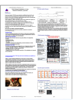
1.7.1 Display Structure and Display Interface of Three-Phase(
(10~30
kVA)
)UPS
ON
OFF
PHASE
WELCOME TO USE KELONG R UPS
RECTIFIER
INVERTER
MODEL :FR-UK3320
INPUT :380V/50Hz
OUTPUT:380V/50Hz
BYPASS
BAT.LOW
OVERLOAD
FAULT
XIAMEN KEHUA HENGSHENG CO., LTD
>>>>>>>>>>>>>>>>>=============
Fig.1-E Display panel structure of three-phase(10~30 kVA)UPS
(2)
(1)
(3)
ON
OFF
PHASE
RECTIFIER
WELCOME TO USE KELONG
R
UPS
INVERTER
BYPASS
MODEL :FR-UK3320
INPUT :380V/50Hz
OUTPUT:380V/50Hz
XIAMEN KEHUA HENGSHENG CO., LTD
>>>>>>>>>>>>>>=============
BAT.LOW
OVERLOAD
FAULT
(15)
(4)
(5)
(6)
(7)
(8)
(9)
(10)
(11)
(12)
(13)
(14)
(16)
Fig. 1-F Display panel interface of three-phase(20~60 KVA)UPS
Explanation :
(1)、LCD display:Show the running parameter and status of UPS(as voltage、current、load etc).
(2)、on button
(3)、off button
(4)、Phase alarm light(red)
:The light will be on when the phase of rectifier input or bypass input
is error.
(5)、Work flow light of rectifier(green)
:The light will be on when the rectifier is normal.
(6)、Work flow light of inverter(green)
:The light will be on when the inverter is normal.
(7)、Bypass alarm light(red)
:The light will be on when there is bypass output.
(8)、Battery low alarm light(red)
:The light will be on when the battery is low.
(9)、Overload alarm light(red)
:The light will be on when the output of UPS is overload.
(10)、Fault alarm light(red)
:The light will be on when rectifier、inverter or bypass is error.
(11)、Page up button:Use when lookup display contents of LCD.
(12)、Enter button:Use when lookup display contents of LCD.
(13)、Backup button:Lookup display contents of LCD.
(14)、Page down button:Use when lookup display contents of LCD.
(15)、Page left button:Use when lookup display contents of LCD and turn on LCD screen light.
(16) EPO Emergency Power Off button: Under emergency situation, press EPO button, it will be
shut down and without output.
1.7.2 Display Structure and Display Interface of Three-Phase(
(40~160
kVA)
)UPS
(9)
(6)
(10)
(11)
PHASE
BYPASS
BATT. LOW
ON
LOAD
FAULT
OFF
MAINTENANCE
INPUT2
INPUT1
BYPASS
AC/DC
DC/AC
OUTPUT
BATTERY
EPO
Fig. 1-G Display panel structure of three-phase(40~160 kVA)UPS
Explanation:
:
(1) LCD display:Show the running parameter and status of UPS(as voltage、current、load etc).
(2) Phase alarm light(red):The light will be on when the phase of rectifier input or bypass input is
on error.
(3) Bypass alarm light(green)
:The light will be on when it is on Bypass. For UPS it’s red, for IPS
it’s green.
(4) Battery low alarm light(red)
:The light will be on when the battery is low.
(5) Overload alarm light(red)
:The light will be on when the output of UPS is on overload.
(6) Fault alarm light(red)
:The light will be on when inverter is on error.
(7) Backup button:Used for lookup display contents of LCD.
(8) Page up button:Used for lookup display contents of LCD.
(9) Page down button:Used for lookup display contents of LCD.
(10) Page down button:Used for lookup display contents of LCD.
(11) Enter button:Used for lookup display contents of LCD.
(12) On button:Used with button 13 for start-up.
(13) Enter button:Used with button 12 for start-up; Used with button 14 for shutdown.
(14) OFF button:Used with button 13 for shutdown.
(15) Indication lamp of manual maintenance bypass workflow (green): Lights on when
maintenance bypass power supply.
(16) Indication lamp of bypass workflow (green): Lights on when bypass power supply.
(17) Utility input indication lamp (green): Lights on when there is utility input.
(18) Rectifier workflow indication lamp (green): Lights on when rectifier is working normally.
(19) Battery workflow indication lamp (green): Lights on when battery power supply.
(20) Inverter workflow indication lamp (green): Lights on when inverter is working normally.
(21) Output flow indication lamp (green): Lights on when there is output voltage.
(22) EPO Emergency Power Off button: Under emergency situation, press EPO button, it will be
shut down and without output.
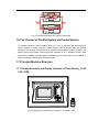
1.7.3 Outlook of three-phase UPS FR-UK series(
(10~30 kVA)
)
Fig. 1-H Outlook of three-phase UPS FR-UK series(10~30 kVA)
Fig. 1-I External view for FR-UK3310~FR-UK3330
1.7.4 Outlook of three-phase UPS FR-UK series(
(40~60 kVA)
)
PHASE
B YPASS
B ATT. LOW
ON
LOAD
FA ULT
OFF
MAINTENANCE
INPUT 2
INPUT 1
BYPASS
AC/DC
DC/ AC
OUTP UT
BATT ERY
EPO
Fig. 1-J The front and rear panel of FR-UK3340~FR-UK3360
1.7.5 Outlook of three-phase UPS FR-UK series(
(80~160 kVA)
)
Fig. 1-K The front and rear panel of FR-UK3380~FR-UK33160
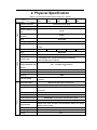
2. Physical Specification
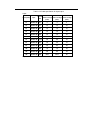
Table 2-1 Physical Specification FR-UK series (10~30kVA)
Model
Specification
FR-UK(/B)
FR-UK(/B)
FR-UK(/B)
FR-UK(/B)
FR-UK(/B)
3310
3315
3320
3325
3330
Rectifier constitution
three-phase-control rectify
380±
± 25%
Voltage (Vac)
Rectifier Frequency range
40~65
Input
(Hz)
SYNC Frequency Tracking
50±
± 5%
range (Hz)
3φ
φ4W+GND
Phase
Battery voltage (VDC)
12V×
×29=348V
Charging Current (A)
Self-adjusting according to capacity of battery, the max. charging current
is 40A
Rated power (kVA)
10
15
L-
-N:
:220
Voltage (Vac)
output
25
30
3φ
φ4W+GND
Phase
Frequency (Hz)
20
L-L:
:380
normal Main power:
:synchronous tracking automatically;
abnormal Main power:
:50±0.2%
Unbalance three-phase
≤2%,
,compatible 100%
%unbalance
voltage stabilization with
full load
Wave form
Sine wave, THD<3% at linear load
Switch time (ms)
0
≥90%
Efficiency
Overload capacity
125% of rated load last for 10 minutes, 150% of rated load last for
1 second
Maintenance switch
Maintenance switch with no switch time
Start-up
LCD display
Provided with DC start up function
Input voltage/ Frequency, Output voltage, Battery voltage, Load, DC
current etc.
LED display
Alarm function
Others
Communication function
Battery test function
Protect function
EMC
Work status of UPS and fault indication
AC input abnormal, Low battery, Overload, Failure
RS232/RS485, dry connection communication signal
Present(
(for details see battery test control in LCD display operation)
)
Output short circuit, Overload, Over-temperature, Battery low voltage,
Output over/low voltage
Meet GB/T 7260.3-2003
Noise(
( dB)
)
<65
Cooling
Fans
Operating
0~
~ 40
Temperature(℃)
0~
~95%,
, No condensation
Relative Humidity
Dimension (W×D×H)(mm)
500×
×800×
×1180
Weight (kg)
185
195
205
220
235
◆ Specifications are subject to change without prior notice.
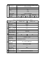
Table 2-2 Physical Specification FR-UK series (40~100kVA)
Model
Specification
FR-UK(/B)
3340
FR-UK(/B)
FR-UK(/B)
FR-UK(/B)
FR-UK(/B)
3350
3360
3380
33100
Rectifier constitution
three-phase-control rectify
380±
± 25%
Voltage (Vac)
Rectifier
Frequency
40~65
Input
range (Hz)
SYNC
Frequency
50±
± 5%
Tracking range (Hz)
3φ
φ4W+GND
Phase
Battery voltage (VDC)
12V×
×29=348V
Rectifier constitution
Self-adjusting according to capacity of battery, the max. charging current
is 40A
Rated power (KVA)
40
50
80
100
3φ
φ4W+GND
Phase
L-
-N:
:220
Voltage (Vac)
Frequency (Hz)
60
L-L:
:380
normal Main power:
:synchronous tracking automatically;
abnormal Main power:
:50±0.2%
unbalance three-phase
≤2%,
,compatible 100%
%unbalance
voltage stabilization
with full load
Wave form
Sine wave, THD<3% at linear load
Switch time (ms)
0
output
efficiency
Overload capacity
≥90%
125% of rated load last for 10 minutes, 150% of rated load last for
1 second
Maintenance switch
Maintenance switch with no switch time
Start-up
others
LCD display
provided with DC start up function
Input voltage/ Frequency, Output voltage, Battery voltage, Load,
DC current etc.
LED display
Work status of UPS and fault indication
Alarm function
AC input abnormal, Low battery, Overload, Failure
Communication
RS232/RS485, dry connection communication signal
function
Battery test function
Present(
(for details see battery test control in LCD display operation)
)
Output short circuit, Overload, Over-temperature, battery low voltage,
Protect function
Output over/low voltage
EMC
Meet GB/T 7260.3-2003
Noise(
( dB)
)
<65
Cooling
Fans
Operating Temperature
0~
~40
(℃)
0~
~ 95%,
,No condensation
Relative Humidity
Dimension
(W×D×H)(mm)
800×800×1600
Weight (kg)
430
1000×800×1800
450
470
680
705
Specifications are subject to change without prior notice
Table 2-3 Physical Specification FR-UK series (120~160kVA)
Model
FR-UK(/B)
Specification
33120
FR-UK(/B)
Commutation
Three-phase commutation
Voltage (Vac)
380±25%
Rectifier
Input
Frequency range
SYNC
40~65
(Hz)
Frequency
Tracking range
50±5%
(Hz)
Phase
3φ
φ4W+GND
Battery voltage (VDC)
12V×29=348V
Charging current (A)
33160
Self-adjusting according to capacity of battery, the max. charging current
is 40A
Rated power (KVA)
120
160
3φ
φ4W+GND
Phase
L-
-N:
:220
Voltage (Vac)
Frequency (Hz)
L-L:
:380
normal Main power:
:synchronous tracking automatically ;
abnormal Main power:
:50±0.2%
output
unbalance three-phase
voltage
≤2%,
,compatible 100%
%unbalance
stabilization
with full load
Under linear load: THD<
<3%
Parallel form
Unbalance degree of
0
load current in parallel
Wave distortion
Others
Switch time (ms)
Maintenance switch
Start-up
≥90%
125% of rated load last for 10 minutes, 150% of rated load last for 1
second
Maintenance switch with no switch time
provided with DC start up function
LCD display
Input voltage/ Frequency, Output voltage, Battery voltage, Load, DC
current etc.
LED display
Alarm function
Communication
function
Battery test function
Protect function
UPS‘ s operation activity status
Overload, AC input abnormal, Low battery, Failure
RS232/RS485, dry connection communication signal
Present(
(for details see battery test control in LCD display operation)
)
battery low voltage, Overload, Over-temperature, Output short circuit,
Output over/low voltage
EMC
Meet GB/T 7260.3-2003
Noise(
(dB)
)
<65
Cooling
Fans
Operating Temperature
0~
~40
(℃)
)
0~
~95%,
,No condensation
Environment Humidity
Dimension
1000×800×1800
(W×D×H)(mm)
Weight (kg)
745
◆ Specifications are subject to change without prior notice.
805
3. Installation for UPS
3.1 Installation instruction
1.Please check if the grid connections, including various contacts and socket are in good condition,
to avoid open circuit or short circuit.
2.For the single-phase three-wires input UPS, the grounding connection must be good, and the
voltage between neutral wire of utility and ground wire in machinery room should be under 5V;
if the AC input ground wire is floating, the voltage between input neutral wire and ground wire
may reach 100V; If the user has strict requirement for the voltage between neutral wire and
ground wire, please note that AC input ground should be good to avoid unnecessary losses.
3. When installing the UPS, do not reverse connecting the input and output neutral wire, live wire
and ground wire of UPS or wrong connecting, so as not to cause electrical short circuit; also
should check if the input mains voltage is normal.
4.When install the long backup time battery pack, be sure to connect them according to the
battery installation instructions, and connection wiring must be locked, the battery's positive and
negative short-circuit are prohibited, any contact with the battery connection wire terminal or
bare wire terminals is prohibited, or may result in battery damage or personal injury. When
connect the battery pack with UPS, check battery voltage is consistent with the provisions of
UPS.
5.UPS Installation Requirements:
◆Please put UPS on the flat ground (to avoid tilt, uneven ground)
◆Do not place objects on top of the UPS, personnel should not sit on top of UPS.
◆Avoid placing UPS in sunlight, rain or wet places.
◆Do not place the UPS in the place with corrosive gas.
3.2 Installation Steps
Three phase UPS FR-UK series(10~160 kVA)installation flow chart as Fig 3-1shown.
Prepare for
installation
inspecting
environment
Unpacking,
inspecting
equipment
installing UPS
installing Battery
cabinet
cable
connection
Check-up
installing options
and accessories
Fig 3-1System installation flow chart
Instruction:
:
To install and set the UPS by the manufacturer or manufacturer authorized personnel.
3.3 Preparing for Installation
3.3.1 Check the installation site
Caution:
:
:
Beforeg in s installing the UPS, on-site environment should be meet the basic conditions
of equipment operatin afety and good condition. If the on-site environment does not
meet the basic criteria, please transform the scene accordingly. Only meet the basic
condition, the UPS could be installed.
3.3.1.1 The basic requirements of the environment
Ambient temperature:0℃~+40℃;
Relative Humidity:0%RH~95%RH,No condensation;
Cooling: Air Cooled;
Altitude:Consistent with GB / T 7260.3-2003 requirements;
Vertical:No vibration and no more than the vertical gradient 5º;
Pollution Level:Class Ⅱ 。
UPS should be installed with sufficient ventilation, cooling, humidity not high and dust-free
environment. Recommended operating temperature is 20 ~ 25 ℃, humidity at 50%
Caution:
:
:
Install the UPS in a metal conductive dust working environment is prohibited.
3.3.1.2 The basic requirements for power supply
1. Grounding preparation. Ground terminal is ready, voltage between the neutral wire and ground
wire should not exceed 5 V.
2. AC input voltage and load capacity of main input line
Before UPS be installed, make sure that the AC input voltage and load capacity of main input
lines are meet the equipment requirements, and consider whether the carrying capacity will
decline caused by wire aging.
Three-phase UPS FR-UK series (10 ~ 160kVA) require AC input voltage range of 380 ± 25%
(Vac). The UPS system capacity should be greater than the maximum input power.
3. Configuration of the AC input breaker protection
Configure with a UPS capacity compatible breaker or distribution box before the installation of
UPS cable, so as to separate with UPS and main. Taking into account the impact of
instantaneous power current, the breaker should be 1.5 to 2 times current of the UPS input
maximum current, and the breaker with the air leakage protection is not allowed to prevent
breaker malfunction. Breaker selection please refer to Table 3.3 -1:
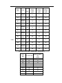
Table 3.3-1 Input\Output breaker capability:
Breaker capability
Power (kVA)
Input
Max. current (A)
10
220/380V 3Φ
24
32
15
220/380V 3Φ
35
50
20
220/380V 3Φ
47
50
25
220/380V 3Φ
59
63
30
220/380V 3Φ
70.5
100
40
220/380V 3Φ
94
100
50
220/380V 3Φ
117.5
125
60
220/380V 3Φ
141
160
80
220/380V 3Φ
188
200
100
220/380V 3Φ
235
250
120
220/380V 3Φ
281.8
300
160
220/380V 3Φ
375.8
400
(A)
Table 3.3-2 input/output breaker capability
Breaker capability
Power( kVA)
Output
Max. current (A)
10
220/380V 3Φ
16
32
15
220/380V 3Φ
23
32
20
220/380V 3Φ
30
50
25
220/380V 3Φ
38
63
30
220/380V 3Φ
45.5
63
40
220/380V 3Φ
60
100
50
220/380V 3Φ
75.8
100
60
220/380V 3Φ
91
125
80
220/380V 3Φ
121
160
100
220/380V 3Φ
151.5
200
120
220/380V 3Φ
182
250
160
220/380V 3Φ
242
300
(A)
4. Input and output cable selection
UPS AC input, output cable, battery cable wire cross-sectional area of the selection , please
refer to table 3.3-3.
Table 3.3-3 Cable specification for input/output
Input:
Power(kVA)
Input
Current
( A)
Live wire
Neutral wire
Ground wire
Section acreage Section acreage Section acreage
2
2
2
(mm )
(mm )
(mm )
10
220/380V 3Φ
23
6
6
4
15
220/380V 3Φ
35
10
10
10
20
220/380V 3Φ
46.5
10
10
10
25
220/380V 3Φ
59
16
16
10
30
220/380V 3Φ
70.5
16
16
10
40
220/380V 3Φ
93
25
25
10
50
220/380V 3Φ 117.5
25
25
10
60
220/380V 3Φ
141
35
35
16
80
220/380V 3Φ
144
50
50
25
100
220/380V 3Φ
180
70
70
35
120
220/380V 3Φ
210
95
95
35
160
220/380V 3Φ
288
50×2
50×2
50
Output:
Power
(kVA)
10
15
20
25
30
40
50
60
Cable
80
100
120
160
Curren
Output
3Φ
220/380V
3Φ
220/380V
3Φ
220/380V
3Φ
220/380V
3Φ
220/380V
3Φ
220/380V
3Φ
220/380V
3Φ
220/380V
3Φ
220/380V
3Φ
220/380V
3Φ
220/380V
3Φ
Neutral wire
Ground wire
Section
Section
Section
acreage
acreage
acreage
(mm2)
(mm2)
(mm2)
15
6
6
4
23
10
10
10
29
10
10
10
36
16
16
10
46
16
16
10
58
16
16
10
72
25
25
10
92
25
35
10
121
35
35
16
151
50
50
25
182
70
70
35
243
95
95
50
t
(A)
220/380V
Live wire
connected to battery (BAT. Voltage range:300-410 VDC):
Power
(kVA)
Section acreage of
Max. Current(A)
wire
(mm2)
10
26
6
15
38
10
20
51
16
25
64
20
30
77
25
40
102
25
50
128
35
60
153
35
80
240
70
100
310
95
120
360
95
160
480
50×2
Above sectional area of the cable connection is just for about 5 meters cable reference, if
the length is more than 20 meters, the wire cross-sectional area has to be increased
correspondingly.
5. Lightning facility
Frequent lightning area, the main input should be equipped with multi-degree lightning
protection systems to ensure safe operation of equipment. Outdoor installation should
increase the level of the lightning of AC input power.
3.3.2 Unpacking and Inspection
3.3.2.1 Transportation
1. Arrange the appropriate means of transport and lifting (eg forklifts) according to the product
packing dimension.
2. Due to the product’s size are large, please unpack at the chosen location. The installation
site should be near to the unpacking locations as near as possible.
3. Please pay attention to the turning corner, the slope of uphill and downhill during
transportation process to prevent the equipment from the collision.
3.3.2.2 Unpacking
1. When installing, please move the equipment to the installation site, then unpacking it.
2. After unpacking, please check the system components are correct and complete
according to the packing list.
Tips:
For your convenience in case of the transport and packaging in the future, please put the
packaging material in the box and preserve them properly. Note: If you find the
components does not match with the packing list of the contract, please record them
timely, and contact with Kehua local Branch or office or distributor immediately
3. After unpacking, check whether the equipment has mechanical damage caused by
transportation.
Tips:
:
If you find the UPS has serious damage in appearance, please check further, please
record them timely, and contact with Kehua local Branch or office or distributor
immediately.
3.4 Equipment Installation
3.4.1 Installation Notes
1. Do not place in areas with corrosive gases. Ensure that the equipment be placed in
well-ventilated location, to facilitate heat dissipation
2. The UPS should be placed in a horizontal place, avoid placing in the rugged, sloping areas.
Do not put objects on top of the cabinet.
3. Switch the breaker “OFF” before Wiring. Do not reversely connect the ground with the
neutral line, live line with the neutral line, in case of causing electrical short circuit. Note it
should be well grounded, neutral line and ground line voltage should be no higher than 5 V.
If the UPS system output are through the transfer appliances, please check the quality of
the transfer electrical appliances so as not to cause open or short circuit.
3.5 Check the main input
Please re-confirm if the network load capacity are able to meet the requirements of UPS,
whether mains power supply are complied with UPS nameplate’s voltage and frequency,
whether the aging of the wire caused carrying capacity decline. If any question, please contact
the local main supplier.
3.6 Installation of UPS
3.6.1 Installation steps of three-phase UPS FR-UK Series
(10~
~30 kVA)
Remove the UPS from pallets to ground for installation. Below is the installation introduction
for the three-phase UPS FR-UK Series(10~30 kVA)
1. The external structure of three-phase UPS FR-UK series (10~30 kVA) is as followed after
unpacking:
Fig. 3-2 10~
~30kVA UPS Installation steps 1
2. Select and plan installation site, drive 4 pieces of M10 expansion bolts into the ground.
Required distance:506mm×525mm,the height of exposed expansion bolts should be
constricted to within 50mm, details as shown below:
Fig. 3-3 10~
~30kVA UPS Installation steps 2
3. Take down the bolts which connect UPS and pallets and remove main unit from pallet to
ground which already has anchored by M10 expansion bolts, locking bolts, as below:
Fig. 3-4 10~
~30 kVA UPS Installation steps 3
4. Connect UPS Input & Output cable According to “3.9 Electrical connection” ;
5. Installing the bolt and seal plate of base into the foundation of mian unit, as shown below:
footborad for
installation
hole of
cable-out
installating
Adjustable
bolt in it
Fig. 3-5 10~
~30 kVA UPS Installation steps 5
3.6.2 Installation steps of three-phase UPS FR-UK Series
(40~
~160 kVA)
Remove the mian unit of UPS from brackets to ground for installation. The installation steps of
three-phase UPS FR-UK series (40~160kVA) are identical. Below take the installation of
FR-UK series (80~160kVA) as examples to explain:
1. The external structure of three-phase UPS FR-UK series (80~160 kVA) is as followed after
unpacking:
Fig. 3-6 80~
~160 kVA UPS Installation steps 1
2. Choose and layout installation site, drive 8 M10 expansion bolt into ground. Required
distance as shown below,the exposed height of expansion bolt should be controlled within
50mm. Details as below:
expansion bolts
Fig. 3-7 40~
~60 kVA UPS Installation steps 2- size chart for Expansion bolt
expansion bolts
Fig. 3-8 80~
~160 kVA UPS Installation steps 2- size chart for Expansion bolt
3. Take down bolt that connect mian unit and bracket,remove mian unit from bracket to
ground which have anchored by expansion bolt,locking bolts, as shown below:
Installed position
of expansion bolt
Cover board
Fig. 3-9 80~
~160 kVA UPS Installation steps 3
4. Connect Input & Output wire of UPSS based on “3.9 Electricity connection”.
5. Installing the bolt and seal plate of base to the foundation of main unit, as shown above.
3.6.3 The structure of base plate of three-phase UPS FR-UK
Series (10~160 kVA)
footboard
holes for taking
cable out or in
holes for
Adjustable bolts
Fig. 3-A the structure of base plate of three-phase UPS FR-UK Series (10~30 kVA)
back
front
Fig.3-B the structure of base plate of three-phase UPS FR-UK series (40~60 kVA)
back
front
Fig. 3-C the structure of base plate of three-phase UPS FR-UK series (80~160 kVA)
3.7 Battery Cabinet Installation
Caution:
:
:
UPS & Battery Cabinet should be purchased separately.
3.7.1 Important safety rules
Forced open or disassemble a battery is prohibited. Because of the internal electrolyte is
harmful to skin and eyes. When you replace the battery in order to avoid the risk of electric
shock and short circuit , please pay special attention to the following preventive measures:
1. Do not wear watches, rings or other metal jewelry;
2. Use tools with insulated handle;
3. Do not put tools or metal objects on top of the battery;
4. Do not let the fire near to the battery; no smoking.
3.7.2 Installation step
1. To ensure safe operation and avoid unnecessary damage to the equipment, the
assembly work of UPS with external battery has to be done by the personnel with technical
expertise according to following program operation:
1) Connect the external battery pack cable, but do not connect with UPS external battery
input terminal;
2) Connect the input power line with UPS, but make sure that the correctness of polarity
and voltage specifications meet the requirements of UPS.
2. When the AC input is normal and UPS without any load, turn on the UPS breaker and
measure input DC voltage.
3. After the charging voltage is normal in Step "2", turn off the UPS. And connect UPS with the
battery pack, check if the polarity of UPS and battery pack are correct.
4. After assembly, the UPS can be used after testing done
3.8 (Parallel) System installation
Install the system according to previous described methods, install the battery pack and UPS
host of the parallel system respectively; connect the AC output of the parallel unit to the
distribution box of parallel system.
Caution:
:
The AC input connection, phase sequence of the parallel system units should be strictly
consistent, to ensure that bypass parallel system have the same power phase.
Connect the parallel port of each unit by the shielded communication line, and fasten the
corresponding RS232 fastening screws.
3.9 Electrical connection
3.9.1 Wire modes of single UPS
Connect cable accompanied with UPS to relative terminal and ensure reliable connection.
Caution 1:
:
When wiring, make sure there should be linked firmly between input & output wires and
input & output terminal. Not allow to loose contact or connect inversely!
Caution2:
:
When applying single machine, no further wiring is needed for bypass live sire and
bypass Null wire.
N
N output
U output
V output
W output
Earthing
N input
AC OUTPUT
U
V
PE
W
N
AC INPUT
U
V
PE
W
BATTERY
+
BAT. BAT. +
Earthing
W input
V input
U input
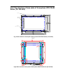
Fig. 3-D Terminal wiring chart of Three-phase UPS FR-UK series (10~30 kVA)
FUSE
BATTERY
-
+
AC OUTPUT
U V W
AC INPUT
U
PE
N
V W
Fig. 3-E Terminal wiring chart of Three-phase UPS FR-UK series (40~60 kVA)
ON
ON
ON
ON
OFF
OFF
OFF
OFF
Breaker
Output
Breaker
Maintenance Bypass
Breaker
Bypass
Breaker
AC input
ON
OFF
Breaker
Battery
FUSE
FUSE
N
Neural
U
V
W
Live wires
Ouput
U
V
W
Live wires
AC input
-
BAT."-"
+
GND
BAT."+"
Earthing
Fig. 3-F Terminal wiring chart Three-phase UPS FR-UK series (80~160 kVA)
Caution:
:
Three phase live wire using U、
、V、
、W as identification methods, corresponding to A phase,
B phase, C phase, or the R phase, S phase, T phase.
3.9.2 Method of Connection for the two units of UPS by Hot
Standby System.
3.9.2.1 Connection steps
1. Dismantle the breaker cover board in the front of the UPS (connection bar), visible the breaker
and connection terminal.
2. Connect output three-phase live wires of slave unit to the bypass input breaker in order, the
output neural of slave unit to the input neutral of main unit, see below detail specification.
Caution:
Utility input phase order should be right, or machine cannot start normally and the
wrong phase order connection should be corrected. Phase order indicator on panel will
light on.
3. Connect the utility input of main unit to the utility input of slave unit.
4. Other connection is the same as the connection of single unit.
5. Check all connection, make sure the connection is right, re-install and tighten the breaker cover
board of both main and slave unit.
3.9.2.2 Connecting way
1.Connecting ways of Three- phase FR-UK series (1~30 kVA) Serial Hot Standby System
Slave
RS232/485
电涌保护器
注意:维护时请拆下此盖板。
PALL.1
电涌保护器
注意:维护时请拆下此盖板。
Surge Protector
Attention:when maintain the surge protector,
please remove this cover-board.
Surge Protector
Attention:when maintain the surge protector,
please remove this cover-board.
SNMP
SNMP
市 电
POWER
维护旁路
MAINTENANCE
旁 路
BYPASS
PALL.2
PALL.2
输 出
OUTPUT
RS232/485
SIGNAL
PALL.1
SIGNAL
输 出
OUTPUT
电 池
BATTERY
市 电
POWER
维护旁路
MAINTENANCE
旁 路
BYPASS
电 池
BATTERY
Connect Main
uint's Bypass
and Three-phase
live wire of Slave's
ouput by short wire
Get rid of
short wire
N
AC OUTPUT
U
V
PE
W
N
AC INPUT
U
V
PE
W
BATTERY
+
-
N
AC OUTPUT
U
V
PE
W
N
AC INPUT
U
V
PE
W
BATTERY
+
-
电池正极 电池负极
Conect to Load
Conect to Host's
BAT. Cabinet
AC input
Conect to Slave's
BAT. Cabinet
Fig. 3-G Connecting ways of Three- phase FR-UK series (1~30KVA) Serial Hot Standby
System
Connection Description:
Dismantle the short wire connecting between bypass input breaker and utility input breaker of main
unit, and dismantle neutral of input. Connect the Three-phase live wires of standby unit to the
bypass input breaker in order; the output neutral of standby unit to input neutral of main unit.
2.Connecting ways of Three- phase FR-UK series (40~60 kVA) Serial Hot Standby System
Slave
Host
Dismantal short
cuprum board
FUSE
BATTERY
-
+
AC OUTPUT
U V W
AC INPUT
U
V W
N
PE
FUSE
BATTERY
-
+
AC OUTPUT
U V W
AC INPUT
U
V W
PE
N
Connect to Slave's BAT. cabint
Connect to
Host's BAT. cabint
Connect to Load
AC input
AC input
Fig. 3-H Connecting ways of Three- phase FR-UK series (40~60 kVA) Serial Hot Standby
System
Connection Description:
Dismantle the short cuprum board connecting between bypass input breaker and utility input
breaker of main unit, and dismantle neutral of input. Connect the Three-phase live wires of standby
unit to the bypass input breaker in order; the output neutral of standby unit to input neutral of main
unit.
3.Connecting ways of Three- phase FR-UK series (80~160 kVA) Serial Hot Standby System
Connnect to
Slave's Group
+
-
V
U
+
-
AC input
N Wire
Ground wire
BAT."-" BAT."+" GND
V W
Power
Output
Connect to Load
W
N
AC 220V/10A Max.
U
V
Breaker
ON
OFF
Breaker
AC output
Maintenance Bypass
OFF
ON
U
V W
Bypass
U
Connnect to
Host's Group
Earthing
N
PALL. 2
PALL. 1
Bypass
BAT.
Breaker
AC input
Breaker
AC input
W
V
U
AC Output
Maintenance Bypass
Bypass
AC input
W
FUSE
FUSE
BAT."-" BAT."+" GND
PALL. 1
FUSE
FUSE
BAT.
AC input
ON
OFF
Breaker
OFF
Breaker
ON
ON
OFF
Breaker
OFF
ON
Breaker
ON
OFF
Breaker
AC output
OFF
Breaker
ON
ON
OFF
OFF
ON
Ground wire
Earthing
PALL. 2
RS232/485
SIGNAL
SNMP
Slave
AC 220V/10A Max.
RS232/485
SIGNAL
SNMP
Host
Fig. 3-I Connecting ways of Three- phase FR-UK series (80~160 kVA) Serial Hot Standby
System
Connection introduction:
Three-phase live wire of main unit connect to bypass breaker of main unit in order:output netual
wire of salve unit connect to input netual wire of main unit.
If user need change the machine to Serial Hot Standby System, then it should be informed to the
UPS manufacturers in advance, so the manufactures can apply to provide the required copper bar
request for changing the main unit. Main unit change as follows: Dismantle maintenance bypass
breaker of main uint, short wire connecting copper bar of the bypass breaker and utility, dismantle
three bypass breaker connecting piece of main unit, install copper bar offered by UPS manufacture
in three input terminal of bypass breaker, then short connect live wire of maintenance bypass
breaker to bypass breaker in order, see the figure below.
Host
SNMP
AC 220V/10A Max.
SIGNAL
ON
OFF
Breaker
AC output
ON
ON
OFF
Breaker
Maintenance Bypass
ON
RS232/485
ON
OFF
Breaker
OFF
Breaker
OFF
Breaker
Bypass
AC input
Battery
FUSE
FUSE
PALL. 1
N
U
V
W
Live wire
AC output
U
(Back board)
V
W
U
Bypass input
V
AC input
W
-
PALL. 2
+
BAT."-" BAT."+" GND
Earthing
short copper barconnectig copper
bar
connect to
of Bypass breaker
Maintenance
Bypass
breaker and
Bypass breaker
Fig. 3-J Charging copper bar for al Hot Standby System
Caution:
Three-phase live wire as U, V, W shown in figure above, are corresponding to A phase,B
phase, C phase, or R phase, S phase, T phase.
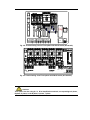
3.9.3 Connecting way of Parallel System
3.9.3.1 Connection steps
1、Uncover UPS breaker cover board of front panel, find the breaker and connection terminal.
2、Connect the wires of input, output and battery: pay attention on the battery polarity must be
connected correctly.
3、Output “N、U、V、W” of the UPS1, UPS2 should pigtail from the terminal of UPS1、UPS2
the user’s distribution cabinet, and short connect on distribution cabinet; UPS has output
breaker, so the user no need to set breaker on the distribution for output circuit of each UPS,
but there should be a main breaker at the output after two units of UPS installed in parallel.
4、Connect the parallel cables according to the following figure.
Caution::
:
A. If utility supply input phase sequence connects wrongly, the machine should not
start up normally, and the PHASE director will lights on. Adjusting the input phase
sequence if it connects wrongly.
B. Make sure the input and output phase sequence of two units connects correctly
before connect the two UPS to utility, please use multimeter to test Input Voltage
phase A, B phase voltage, C phase voltage of two UPS, and they should be less than
5V.
5. Using shielded communication cable connecting all parallel systems and ports, also fastening
the corresponded RS232 screws.
3.9.3.2 Connecting way
-
Input
Live wire
Input
Neutral
Live wire
Neutral
Ouput to Load
W
V
U
Breaker2
N
PE
W
AC OUTPUT
U
V
N
-
Breaker1
+
BATTERY
PE
W
N
AC OUTPUT
U
V
W
PE
N
AC INPUT
U
V
Connecting wire KH03 for
Parallel System
PALL.2
PALL.1
UPS1
Connect to Host
Breaker3
+
AC INPUT
U
V
UPS2
W
PE
PALL.1
PALL.2
BATTERY
1. Three-phase (10~30 kVA) series UPS Parallel System connection is shown as following:
Fig. 3-k Three-phase (10~30KVA) series UPS Parallel System connection
2. Three-phase (40~60KVA) series UPS Parallel System connection is shown as following:
W
Breaker2
W
N
U
-
Earthing
Ouput to Load
Breaker1
W
Output live
wire
U
V
AC Input
Input live
wire
W
Breaker3
-
+
PALL. 1
GND
Connect to UPS2
BAT. Group
BAT."-" BAT."+"
SIGNAL
Earthing
PALL. 2
RS232/485
PE
Breaker 1
Connect to UPS1
BAT. Group
BAT."-" BAT."+" GND
V
OFF
Breaker
Battery
FUSE
+
OFF
Breaker
AC input
FUSE
PA LL. 2
OFF
Breaker
Bypass
FUSE
PALL. 1
OFF
Breaker
Maintenance Bypass
FUSE
OFF
Breaker
AC output
SNMP
FUSE
Neutral
V
Input live
wire
U
OFF
Breaker
Battery
ON
N
V
OFF
Breaker
AC input
ON
V W
Output live
wire
U
OFF
Breaker
ON
AC INPUT
Bypass
ON
U
OFF
Breaker
ON
UPS2
U V W
Maintenance Bypass
ON
A C 220V/10A Max.
AC OUTPUT
OFF
Breaker
AC output
ON
RS232/485
+
ON
SIGNA L
-
ON
SNMP
BATTERY
ON
UPS1
PALL.1
N
AC 220V/10A Max.
UPS1
PALL.2
UPS2
PALL.1
BATTERY
+
AC OUTPUT
U V W
U
Ouput Live wire
Connect to Load
U
PALL.2
Connecting wire KH03 for Parallel System
FUSE
AC INPUT
V W
N
U V W
V W
PE
Breaker 2
Breaker 3
N
Input Live wire
Connect to Host
Output & Input
Neutral
Fig. 3-L Three-phase (40~60KVA) series UPS Parallel System connection
3. Three-phase (80~160KVA) series UPS Parallel System connection is shown as following:
Fig. 3-M Three-phase (80~160 kVA) series UPS Parallel System connection
3.10 System Inspection and testing
3.10.1 Check electrical connections
After completion of electrical connections, please check electrical connections required per
items listed in Table 4.10-1
Table 3.10-1 Check the list of electrical connections
No
Items to be checked
Result
1
Check if the color AC line cable is compliant with regulation
Y□
N□
2
Check if there is any loose wiring in the cabinet
Y□
N□
3
Check if the security labels of the AC power distribution
Y□
N□
units are complete
4
Check if the cable connections are secure
Y□
N□
5
Check if the battery cable’s polarity and sequence are
Y□
N□
correct
6
Check if the cable is correctly identified
Y□
N□
7
Check if the cabling is neat, whether the cable lashing is
Y□
N□
Y□
N□
compliant with process specification
8
Check if the installation and wiring is conducive to the
system’s transformation, expansion, maintenance in the
future.
3.10.2 UPS testing
Testing UPS:It can simulate the main power failure situation by disconnect bypass input
breaker or the main input breaker. When the main are off power, the main "LINE" LED will
go out, and the buzzer will sound once every 5 seconds.
3.10.3 Connect with the load
Only after UPS starts and enters into the stable work, then open the load device; first start
high-power devices, then start small power equipment. Some devices has large starting
current which may cause overload protection (or bypass operation), it is better to start such
equipment before the other devices.
4. Operation
4.1 Notes of using UPS
1. Please check if the load is appropriate before turn on the UPS. The load shall not exceed
the rated output power UPS systems, to avoid of UPS overload protection.
2. Do not use the breaker of UPS as the load breaker, to avoid of the frequent start of the UPS
3. Only after UPS starts and enters into the stable work, then open the load device; Some
device has large starting current which may cause overload protection, it is better to start
such equipment before the other devices. first start high-power devices, then start small
power equipment. If close the UPS, please be sure to close the load device before close
the UPS.
4. When the main is cut off, if the UPS’s power supply is from the generator, please start the
generator first. After the generator is stable, then it can connect with UPS, or it may cause
UPS or load damaged. Please turn off the main input breaker before close the generator.
4.2 UPS single unit operation process
Operation process as Fig.
Fig. 4-1. It needs inspection before power on when start the UPS
first time, refer to Section 4.3.1. When the inspection is approved, the UPS can be turned on.
If UPS would not be used for long-term, it is also needed to inspect before power on when
restart using.
Fig. 4-1 single unit operation process
4.3 Operation instruction
4.3.1 Inspection before power on
Before power on the UPS, please inspect according to follow requirements for testing.
The UPS can be started only after the inspection is passed.
1. Confirm the main breaker (POWER), the battery breaker (BATTERY), and power breaker
have been placed on the "OFF" state.
2. Inspect the load
(1) Confirm the load is non-inductive load. UPS is not recommended to connect with the
inductive load, such as motors, fans, air conditioners and other loads, such loads use
the grid power directly.
(2) Make sure that the load is turned off. Meanwhile, the load capacity shall not exceed the
UPS rated output capacity, otherwise it will cause the system overload protection.
Calculation of load capacity as follow:
FR-UK series UPS load capacity are designed according to 80% (nominal rated power) of the
resistive load, in general FR-UK with computer load can withstand the maximum load number
n estimated as following:
n
∑ pi ≤ p
i =1
P is UPS output capacity(VA),Pi is the No. 1 load VA
For example:One user has the following nominal power of the computer equipment
IBM PC:220V/1.5A (330VA)
LQ1600K printer:220V/1.0A (220VA)
14" color display monitor:70W
Total capacity=330(VA)+220(VA)+70/0.6(VA)=667(VA)。
Select 5KVA Nominal capacity UPS, it can withstand 7 to 8 sets of above equipments.
3. Confirm the UPS has no short circuit between the input live line and neutral line , no short
circuit between the live line and the ground line. Confirm no short circuit between the output
lines by the same method.
4. Detect the AC voltage with a multimeter at AC input terminals (INPUT) The required AC
input voltage range is 380 V± 25%, or it needs to start UPS without main input.
5. Detect the DC voltage with a multimeter at input terminals (BAT.) The required battery
voltage is 348 ~ 400V DC, to prevent the battery cable connection fault.
4.3.2 Single Unit Bootstrap procedure of Three-phase UPS (10~160
kVA)
The bootstrap should follow the steps as:
1. Turn on bypass power breaker (bypass):
Power board begins to work, LCD on the panel initiate displaying. Then low battery indicator
will light on.
2. Turn on rectifier breaker (power):
Supposing the right input power initiate rectifier automatically, the rectifier indicator (Rectifier)
on panel will light on. DC voltage will be established completely after 20s time prolong, and
Battery low indicator (BAT.LOW) will terminate.
3. Turn on battery breaker (battery):
Turn on battery breaker, rectifier start to charge battery.
4. Turn on the inverter system:
(1) FR-UK series (10~30KVA) inverter turn on steps:
At startup, just press “
”on the panel more than 1 second, DC/AC indicator on the
panel will light on. After 30s, close the output breaker, then the output indicator light on,
which mean the UPS inverter output normally.
5. Turn on the load:
When the inverter output is normal, then turn on the load. Please do remember toad the
alod according to this: high capacity load first, then lower capacity load.
4.3.3 Start the load
Observe the indicator on the panel to determine the operational status of UPS. When it i
ndicates the UPS is in inverter working mode or battery working mode, it can supply power to
the load.
After the UPS has running about 10 minutes without load, start the load. according the
sequence "high-power equipment → low power equipment" .
Caution:
:
Some devices has large starting current which may cause overload protection (or bypass
operation), it is better to start such equipment before the other devices.
4.3.4 Turn Off UPS
1.Turn off the inverter system:
(1) FR-UK sereis(10~30KVA)inverter off steps:
Push the “OFF” button till the interter close, then the static switch will automatically
transfer the inverter output to bypass output, to supply power to the load without
interrupted.
(2) FR-UK sereis(40~160KVA)inverter off steps::
Push the “
” on the panel at the same time , then the static switch will
automatically transfer the inverter output to bypass output, to supply power to the load
without interrupted.
2. Turn off battery breaker (battery)
If want to turn off all UPS power, please continue to switch off battery breaker, so rectifier
only stock power in DC BUS.
3. Turn off rectifier input breaker (power):
Turn off rectifier breaker, the rectifier can not establish DC power from AC utility to DC
BUS,DC BUS will discharge power slowly, it will take DC BUS about 2 minutes later.
4. Turn off bypass input breaker (bypass):
Before switch off bypass input breaker,you have to assure output load nonuse, or there will
be no power output from output terminal to terminate user equipment power at breaking
bypass input breaker.
The shutting down procedure will be finished after the LCD display or LED indicators light off.
4.4 Operating procedure of Parallel System
4.4.1 Parallel System Start-up
Please keep load off before Parallel System starting up almost, and make sure all of the breaker
off,
Startup steps as following:
1. Turn on the bypass breaker (BYPASS), the power board starts to working, the LCD display
panel starts to display, and the BAT.LOW indicator lights on and the buzzer beeps.
2. Turn on rectifier breaker(power)of UPS1 on:
If input phase sequence is correct, the rectifier initiates automatically, the rectifier indicator
(RECTIFIER) on panel will light on. DC voltage will be established completely after 20s delay,
and BAT.LOW indicator turns off and buzzer stops beeping.
3. Turn on the battery breaker (BATTERY) of UPS1:
Turn on battery breaker, and rectifier starts to charge battery.
4. Press “ON” button on the panel, switch UPS output breaker on, UPS will come into normal
invert output after 30 seconds. Use multimeter to check out if UPS output voltage and
frequency are normal. Output breaker of UPS1 must be switched off renewedly after normal
output! But keep UPS1 on.
5. Follow steps 1~4 above to finish the bootstrap of UPS2.Keep output breaker of UPS2
ducting until normal output of UPS2.
6. Using multimeter, measure voltage differences of double ends of breakers of output phase
A 、B、C separately (breaker of UPS1 is cut-off), and the voltage differences accord with the
respective differences of UPS1 and UPS2 before paralleled. If the voltage difference less
than 10V, the Phase Lock of the two UPS will work normally under the Power status.
7. Cut off the AC input breakers of the two UPS , measure voltage differences of the front lines
of the two UPS in the step 6 again .If voltage differences are still below 10V , the Phase Lock
is working normally under the battery status.
8. Switch output breaker of UPS1 on. Measure the three-phase voltage with multimeter and
output circumfluence (normal below 3A) with clip style measurer after paralleled.
Switch the AC input breakers on, the output voltage of paralleled should be normal and output
circumfluence should be below 3A.
9. If tested normally, switch load breakers of user’s distribution cabinet.
The Parallel System can make power supply for client’s loads. The electrify sequence
references require of single unit.
4.4.2 Parallel System Shut Down
System should not be turned On-Off frequently, or it is abnormal. and then shut down UPS
Parallel system according to following sequence:
1. Shut down all the output loads of the Parallel System firstly.
2. Shut down each UPS according to the shutdown sequence of single unit by pressing the
On-Off key in panel.
3. Turn off the output breaker of UPS1, and then turn off the output breaker of UPS2.(The step
shall be canceled on daily operation.)
4.4.3 Online shutdown Parallel System
When a parallel unit fails, this parallel unit will quit the parallel system automatically with voice
and light alarm. Now, just operate the process according to Picture 5.4-1 to make the failed unit
completely quit from parallel system, and realize online warm maintenance or replacement.
Picture 5.4-1 Online shutdown Parallel Unit
Caution:
:
When the parallel system is working normally, it is better not to quit its output from parallel
system without shutting down parallel unit, otherwise the power system will appear abnormal.
4.4.4 Online start-up Parallel System
When online launching one or more parallel unit is needed, just follow the operation steps on
Fig. 4-2, after the new unit is operating stably, it will enter parallel system automatically and
realize current sharing operation.
Fig. 4-2 online start-up Parallel System
4.4.5 Redundancy and Expansion of Parallel System
1. Redundant Function
When using 2+1 parallel redundant backup design, total output load should not be large than
2 times of single machine rated output. When 1 single machine fails, this single machine could
launch and quit freely without affecting the operation of parallel system, so it could improve
the reliability of power system. When the output exceeds above load, the overloaded single
machine (exceed N/ (N+1) times of single machine rated output) will alarm. For example, for
double machines backup power system, when the load of single machine exceeds 50%, it will
alarm the overloading.
2. Expansion Function
Theoretically, UPS parallel has no quantity limitation. However if the quantity is over many, the
reliability of the whole parallel system will decrease on the contrary, and can not reach the aim
of improving reliability. Therefore, we don’t suggest using parallel mode to extend gross output
power. In the application of UPS parallel system, double machines parallel is frequently used.
4.5 Manual bypass Maintenance Operation Process
Below operations are commonly handled by professionals. Manufactory will not promise to
bear the responsibility of any problems caused by executing these operations by untrained
and unauthorized personnel.
1. Three phases UPS FR-UK series 10-30kva Manual bypass maintenance operation step:
(1). Press OFF button on the panel to turn off the inverter.
(2). Wait till BYPASS light is on, shut down rectifier breaker (mains) and battery breaker
(battery).
(3) Remove the front cover closure panel to maintain a small switch, put the manual
maintenance switch "ON" position, close the bypass breaker (bypass), the output
breaker (output) after 1 second, after the power off 5 minutes, maintenance operation
can be processed.
Caution:
:
It’s forbidden to close output breaker (OUTPUT) when UPS maintenance.
3. After maintenance, open bypass power breaker (BYPASS), output breaker (OUTPUT).
When the power supply is working normally, till bypass light (BYPASS) on the panel is
on, place the manual maintenance switch on “UPS” position; here load gets power from
UPS bypass electricity.
4. Then executing startup and shut down operation according to Chapter 4.3 Operation
instruction.
5 Maintenance Instructions
5.1 Maintenance Guide
Correct maintenance is key to optimal operation of UPS and will prolong the equipment’s
life span
5.1.1 Safety Precautions
The following safe operation procedures shall be observed at any time:
1. Bear in mind that there is dangerous voltage in UPS even if it is not running. Before
maintenance and adjustment, use a multimeter to check if there is existed dangerous
voltage, to ensure that the power supply is switched off and it is safe for operation.
2. Do not wear gold or silver ornaments like rings and watches, etc during operation of UPS.
3. Do not take for granted the safe operation procedures. If you have any questions, please
consult those who are familiar with the equipment.
5.1.2 Regular Maintenance
In order to increase the efficiency and reliability of UPS system, please carry out the following
steps of preventive maintenance regularly.
1. Maintain a clean environment to avoid dust or chemical pollution to the UPS.
2. Wiring check once half a year if the input and output terminals have good contact.
3. Check regularly the operation of draught fans to prevent choking of draught. They shall be
replaced in case of damage.
4. Check regularly battery voltage and UPS working status.
5. Regularly check the working status of the system to ensure timely detection of failures.
5.2 Daily maintenance of battery
1. Battery Charging requirement
(1) When it is in first operation, please turn on the UPS to charge the batteries for 24 hours.
During the charging, the UPS could be still worked, but that battery discharge time would
be lower than standard value if there is a blackout.
(2) Usually, discharge and charge the batteries per 4~6 months. Discharge the batteries to
UPS shut down, then charge the batteries. The charging time should not less than 24
hours.
(3) In high temperature area, discharge and charge the batteries per 2 months. The
charging time should not less than 24 hours.
(4) If UPS is not work for long time, it should charge the batteries every 3 months. The
charging time should not less than 24 hours.
2. It can only wipe with cloth by moistening water when clean the battery case, prohibit the
use of substances other than oil or organic solvents (such as gasoline and thinner).
3. Battery should be stay away from fire and all electrical equipments which is easy to creat
sparks, to aviod an explosion.
4. During the use the battery pack with UPS, it should periodically check the charger whether
is OK, to avoid battery over charging for long time or in not fully charged state. To avoid
excessive battery discharge, it should immediately arrange a fully charging after discharge
(no later than 24 hours). Then it could be allowed to re-discharge. Strictly prohibited
discharging the batteries once again if the batteries are not fully charged, otherwise it will
reduce the battery capacity or even damage the battery.
5. When UPS stop working, please disconnect the battery breaker on the UPS, to avoid the
battery discharge for long time when utility is failure.
5.3 Attentions when replace battery
1. Do not put batteries into fire, to avoid an explosion.
2. Do not open or disassemble a battery, the inside battery electrolyte is harmful to skin and
eyes.
3. In accordance with the instructions on the battery to make the appropriate recovery.
4. For battery replacement, please consult a professional engineer.
5. Must use the batteries in same capacity, type, and battery manufacturer for replacement.
The batteries are in different capacities, types and battery manufacturers are strictly
prohibited to mix use.
6. Hazardous voltage may exist between battery terminals and ground. Before contact the
batteries please check whether there is an existence of dangerous high voltage, to avoid
any dangers to personal safety. Absolutely prohibiting contact the two terminals of battery or
their bare wire ends at same time.
5.4 Troubleshooting
5.4.1 FAQ
When start-up UPS, the UPS is abnormal, please take reference of next chart 5.4-1 to find the
solution. Meanwhile, please check the external environment, such as temperature, humidity
are not meet the requirement or overload.
The following are simple settlement on fault. If the solution is not clear or it is no enough to
solve the problems, please contact the distributor agent for detail.
Table 5.4-1 FAQ
Abnormal phenomena
Fault diagnosis and checking points
Rectifier AC input breaker is not open,
the front panel INPUT light and
RECTIFIER light does not light, FAULT
(1) RECTIFIER panel light
light is on.
does not light
Rectifier input voltage is not within the
normal range, front panel RECTIFIER
light does not light, FAULT light is on.
AC input phase is wrong, LCD will
(2) Phase sequence panel
display wrong message, front panel
lights, the buzzer beeps
phase sequence (PHASE) light is on, the
long time
buzzer beeps long time
Solution
Open rectifier AC input breaker
Input the voltage which is within
the rectifier normal working
Change the rectifier AC input
line phase sequence, usually
exchange any two of U, V, W will
be ok.
Rectifier has not started completely. the Please wait for the rectifier
(3) No output of Inverter, the buzzer beeps long time, the battery starting finished, the Buzzer
beeps lifted.
buzzer beeps long time, under-voltage light is on.
FAULT lights
Output load is overload. OVERLOAD
Reduce UPS load
lights.
(4) Main failure, UPS
crash without output.
(5) LCD&LED lights are not
light
(6) Fan stops rotating
Battery circuit is abnormal
UPS breakers are not open
Power board failure
Check if the battery circuit
switch is normal or if the battery
is damaged。
Open any breakers of UPS in the
front panel
It should be maintained by
professional service personnel.
Phase V output voltage is abnormal, fan It should be maintained by
failure.
professional service personnel.
Outputs are short circuit (short circuit Lift short-circuit point, close the
containing the load itself).
UPS inverter, restart the inverter.
(7) FAULT lights ,the buzzer Inverter heatsink over-temperature
beeps long time
The fuse on the inverter is broken, or
IGBT module is abnormal
Battery discharge occurs under-voltage
protection
Reduce the load, or load evenly
(8) OVERLOAD light is on
Reduce the load
UPS output overload
Replace the fuse or
modules.
Re-start automatically
main input
IGBT
when
(9) The power supply couldn’t If bypass power supply input voltage,
transfer from inverter to frequency is normal
bypass when UPS is Bypass / Inverter SCR driver board
shutdown
failure.
Check the bypass power supply
voltage and frequency
(10) The power supply
Inverter failure
couldn’t transfer from
bypass to inverter when Bypass / Inverter SCR driver board
UPS starts
failure.
Communication cable is inserted into the
wrong place
Communications software is not installed
successfully.
(11) Communication is
Abnormal
Computer communication windows are
set incorrectly
Above problems are ruled out, still can
not communicate properly.
It should be maintained by
professional service personnel.
It should be maintained by
professional service personnel.
It should be maintained by
professional service personnel.
Insert the communication cable
correctly
Install the software correctly
Set the communication port
correctly
It should be maintained by
professional service personnel.
5.4.2 Troubleshooting for single system and parallel system
1. Single system troubleshooting.
When the single unit fails, shut down the UPS power via “OFF” button on UPS panel. If it is
necessary to shut down the user loads, disconnected the UPS input / output breakers, to
ensure that UPS will not be damaged any more.
2. When the host unit fails, how to deal with series back up system? How to deal with it if the
redundant unit fails?
When the host unit fails, shut down the host UPS power via “OFF” button on UPS panel.
Meanwhile, disconnected the host UPS input / output utility and battery breakers, and
contact with engineer for maintenance.
When the redundancy unit fails, shut down the redundant UPS power via “OFF” button on
UPS panel. Meanwhile, disconnected the redundant UPS input / output utility and battery
breakers, and contact with engineer for maintenance.
3. How to deal with the failure from Parallel system?
When one unit from the parallel system fails, shut down this failed UPS power via “OFF”
button on UPS panel. Meanwhile, disconnected this failed UPS input / output utility and
battery breakers, and contact with engineer for maintenance.
6. Panel LCD Display Operation Procedure
6.1 Push Key Function Illustration
There are 5 kinds of functions keys, as following:
This key is “ display upward / parameter setting +”function repeat.
Add parameter at parameter setting.
Push this key mean“ display downward / parameter set.
For multi-lines character display, downward browsing.
At parameter setting, reduce parameter.
Push this key mean “Parameter item set”
For multi-item set in the same page, using this key can alter display.
Push this key to confirm the function.
To confirm the option with“>” mark or parameter set.
Push this key to back to previous page.
For back to upper level operation menu or parameter setting without input.
Push to Light the LCD.
6.2 On/Off Operation
6.2.1 On/Off Operation of Three-phase (10~30 kVA) UPS
On/Off keys of this Series UPS:
Power on ---- Press “
”key about 1s
Power off ---- Press “
”key about 1s
6.2.2 On/Off Operation of Three-phase (40~160 kVA) UPS
This series have “ double buttons combination operation” to prevent the wrong operating.
”
They lie on the panel as:“
Startup ---- press “
”for more than 1s.
”for more than 1s.
Shut down ---- press “
6.3 Display and Related Operation
1. Close the UPS bypass breaker, and connect mains power supply, panel display as:
Welcome to use KELONG
UPS
Machine model: FR-UK3320
Rating input : 380V/50Hz
Rating output: 380V/50Hz
XIAMEN KEHUA HENGSHENG CO.,LTD
>>>>>>>>>>>>>>>>>>==============
It will return to normal standard page after 10seconds. It also can be realized by pressing button
“
” to return normal page directly.
2. Password page to turn on the UPS:
KELONG UPS
Enter Password
Password:0000
Input password to enter the main display page, if password input is error, it will enter the display
page to show you that the password is wrong, shown as follow:
KELONG UPS
Wrong Password
Password:0000
3. Main display page:
KELONG UPS
Output
Vl-n:
I-n:
Load:
R
220V
0A
0%
UPS status:
01-01-2006
S
220V
0A
0%
T
220V
0A
0%
Normal
08:00:00
UPS operation statue as below:
Power off, Normal, Rectifier abnormal, protecting, battery checking, Bypas abnormal, Overload,
Battery testing, Battery Reversal, Parallel cable abnormal, Battery low, Load warning, Battery ok,
Battery capacity down, battery change suggestion, due time of trail, Due time of off, fan failure,
EPO startup, Battery return circuit abnormal and maintenance bypass start, etc..
Then, press X and X at the same time, LCD will display “Setting mode page”, and indicate user to
enter password. Press X or X can change value of cursor site, press to move cursor.
Then press the “
”“
” buttons at the same time, it will turn to the process setting page,
and shows “Please enter the password ”, then press bottons “
set the cursor position data according to moving the “
” or “
” , which could
” button.
4. Process password setting page
KELONG UPS
Settings
password: 000000
If the password is right, it will enter to the process setting page; if the password is wrong, it will
enter to the page which show to you the password is wrong, as follow:
KELONG UPS
Settings
Wrong password!
password: 000000
5. Process setting page:
►
KELONG UPS
settings
Parameters
Battery
Extra
adjust
Choose the cursorposition “►”show to the menue,press the”
(1) Parameter setting page
Choose the parameter page,as below:
Settings-UPS
Model selecting :◄ FR-UK33xx
HalfLoad warning: On
Output voltage:
220V
Output frequency: 50Hz
Bypass voltage:
+15%/-25%
Bypass frequency: +5%/-5%
Menu Options as follows:
”to referring page:
Model: FR-UK33xx(xx=10,15,20,30,40,50,60,80,100,120,160,200,250,300,
320,400)
Output Voltage Setting: 220V/230V/240V
Output frequency Setting: 50Hz/60Hz
Bypass voltage range: +15%/-25%、+20%/-25%
Bypass frequency range: +5%/-5%、+10%/-10%
Under this page, Push “
Push “
” key means the cursor downward, and vice versa. Push “
cursor upward. Push “
Push “
”key to select the Parameter item lying on where cursor “”point to.
” key means the
” key to save it after setting finished and return to the previous page.
” key to return directly to the previous page without saving the setting, the same
below.
(2) Battery page
By selecting the battery page, displays as below:
Settings-Battery
Elapsed capacity: ◄ 0Ah
Battery capacity: 0100Ah
Boost charge adjust: 0V
Float charge adjust: 0V
▼
Entering this page, Ah parameters can be set when the cursor “-” in the position as shown.
Push “
” key to exit this page without saving the setting, push “
” key to saving the
setting and the cursor will turn to “◄ ” and jump to the “Boost charge adjust” setting. At the
moment, push “
” key to set the parameter of “Boost charge adjust” and “Float charge
adjust”(-5V—+5V),The cursor “▼” means there is the next page expanded, including as below:
Battery sessions settings: 29 / 30pcs
Battery Replacement Reminder: On / Off
Please set the number of years: 3 years (1 to 10 years optional)
If the setting of “battery replacement reminder” is off, the option of “Please set the number of
years” is automatically hidden.
(3) Extra page
Settings-Extra
Clear history log:
ECO mode setting:
Maintenance mode:
S/N reentering:
◄
On
On
On
On
The above settings can select to be set “Off”.
When “Clear history log” is set “On”, it will return to some column of records. Push “
and “
”
” keys to delete the record. When the “Clear history log” is set “Off”, then the record
can not be deleted.
(4) Adjustment page
settings-adjustment
bypass adjust
Rectifier adjust
Battery adjust
Output adjust
Push “
◄
”key to move the cursor.
① Bypass adjust page:
bypass adjust
Volt-A adjust: 0◄
Volt-B adjust: 0
Volt-C adjust
0
Push “
” key to move the cursor and select the menu, push “
” key to operate the
adjustment.
② Rectifier adjust page:
Rectifier adjust
Volt-A adjust: 0◄
Volt-B adjust: 0
Volt-C adjust
0
Push “
” key to move the cursor and select the menu, push “
” key to operate the
adjustment.
③Battery adjust page:
Battery adjust
Bat-V adjust:
+16◄
Charge adjust:
0
Discharge adjust:-16
Push “
” key to move the cursor and select the menu, push “
adjustment.
Output adjust page:
” key to operate the
Output adjust
Volt-A adjust: 0◄
Volt-B adjust: 0
Volt-C adjust
0
Push “
” key to move the cursor and select the menu, push “
” key to operate the
adjustment.
The above adjustable range: {"-16"},{"-15"},{"-14"},{"-13"},{"-12"},{"-11"}, {"-10"},{"-9"},
{"-8"},{"-7"},{"-6"},{"-5"},{"-4"},{"-3"},{"-2"},{"-1"},{"0"}, {"+1"},{"+2"},{"+3"},{"+4"},
{"+5"},{"+6"},{"+7"},{"+8"},{"+9"},{"+10"}, {"+11"},{"+12"},{"+13"},{"+14"},{"+15"},{"+16"}.
Caution: -16 to +16 represents the adjustable level, not sure for the number of adjustable volume.
6. Function menu page:
Under the normal display page, push “
” key to display the function menu list of UPS. "►"
mark means the currently selected function.
KELONG UPS
Rectifier data
Bypass data
Output data
Battery data
Operating status
Buzzer control
▼
The menu also lists the following options: Battery management, Language setting, Time setting,
Manufacturer information, Historical event, Password management.
Push “
” key to move “►” mark to the selection in menu. “▲,▼” displayed on
” or “
right up or down of screen stands there is still some matter for up or down rolling.
Push “
” key into the menu with “►” mark.
Push “
” key to turn in output parameter normal display page.
(1) Rectifier data page:
This page displays UPS rectifier 3 phases input voltage, frequency and rectifier DC output
voltage.
Rectifier data
R
S
Voltage:220V
Frequency:
DC voltage:
T
220V 220V
50.0Hz
395V
Push “
” key to back upper menu. Other keys are negative.
(2) Bypass data page:
This page displays UPS bypass 3 phases voltage and frequency.
Bypass data
R
S
T
Voltage:220V
220V 220V
Frequency:
50.0Hz
Push “
” key to back upper menu. Other keys are negative.
(3) Output data page:
This page displays UPS 3 phases output voltage and LOAD percentage for each phase.
Output
R
S
T
Vl-n:
220V
220V
220V
I-n:
0A
0A
0A
Load:
20% 20% 20%
P(kW):
0.0
0.0
0.0
S(kVA): 0.0 0.0
0.0
PF:
0.00
0.00 0.00
Frequency: 0.0Hz
Push “
” key to back upper menu. Other keys are negative.
(4) Battery data page:
This page displays UPS battery voltage and charging/discharging current. When UPS in normal
status, displaying charging current; When UPS in inverting status, displaying discharging
current.(If Ah number of discharge is 0 in the program setting, “Discharge time ” and “Remaining
time” will not display)
KELONG UPS
Battery data
Battery voltage:
384V
Discharge current:
10A
Battery temperature: 30℃
Discharge time:
1H.30M
Remaining time:
1H.30M.
Push “
” key to back upper menu. Other keys are negative.
(5) Operating status page:
This page displays all UPS operating status.
KELONG UPS
Operating status
Phase input
:
Bypass status
:
Rectifier status:
Battery status :
Normal
Normal
Normal
Normal
▼
By the way, there are two lines in this page. Displayed by the mark at right down of screen.
INVERTER STATUS:
NORMAL
OUTPUT STATUS:
NORMAL
LOAD STATUS:
NORMAL
TEMPERATURE:
26℃
INVERTER TEMPERATURE: NORMAL
PARALLEL LINE STATUS:
NORMAL
BATTERY POLAR:
NORMAL
FUSE STATUS:
NORMAL
FAN STATUS:
NORMAL
Push “
” or “
” keys to browse by scroll.
Push “
” key to back upper menu. Other keys are negative.
(6) Buzzer control page
This Series offer UPS silence control ability. When UPS stay in no utility input status, user can
buzz off intermission beeping. But if abnormal status initiated, buzzer will start alarming
automatically without shield control.
KELONG UPS
Buzzer control
Buzzer:
On
◄
Push “
” key to control the buzzer on or off.
Push “
” key to back upper menu. Other keys are negative.
(7) Battery management page
This Series supply UPS battery test function, the principle is reducing the DC output voltage of
the rectifier, to make UPS battery a instant discharging, then to test battery validity under a long
term utility status.
KELONG UPS
Battery management
► Manual test
Auto boost
Expanding submenu as below:
Battery management-Manual test
Test:Off
► Abort
Standard
Deep
Battery management-Auto boost
Auto boost: ◄ On
Period: 02 Month
Time:
01 th,08:00
Entering this page, push “
” key to control “Auto boost” on or off.
When selecting the Auto boost “off”, push “
” key to confirm it and exit the page.
When selecting the Auto boost “on”, there are popups of “Period” and “Time” setting. At the
moment, push “
” key, the cursor“◄” change to “-” and the display jumps to “Time” setting,
then “Period” and “Time” can be set. Push “
” key to save it after setting finished.
(8) Language setting page
This page is for UPS display language switch setting in Chinese/English/Spanish.
KELONG UPS
Language
►Chinese
English
Espanol
Push “
” or “
” keys to control the mark selecting language in Chinese/English/ Spanish.
Push “
” key to confirm the selected status.
Push “
” key to back upper menu. Other keys are negative.
(9) Time setting page:
This Series UPS equipped with timer chip. It can show the present time. On this page, user can
adjust time through the UPS timer chip.
KELONG UPS
Time & Date
Date:2010 - 07 - 16
Time:08 : 00 : 00
-Day : Fri
Push “
” key to control the mark selecting in Year /Month/Day/Hour/Minute/Second.
Through button “
Through key “
” or “
” to increase or decrease both.
” to confirm the modified time parameter and write in the clock chip inside the
UPS. The cursor “-“ changes to “◄”, and jumps to the line of “Week”, press “
” to choose
the settings.
Through key “
”, return to the upper menu page.
(10) Manufacturer Information Page:
This page shows the manufacturer of UPS, model name, version no. and ID address no. of the
device.
There into, ID address no. is the address coding information of communication data frame when
UPS is using RS485 multi-machine network monitoring. It could be set through a group of dial
switches inside the UPS. Generally we do not propose to change the parameter randomly.
KELONG UPS
equipment info
UPS Model
Hardware
Software
UPS ID
Press “
:
:
:
:
FR-UK3320
Version 4.0
Version 4.0
◄ 01
”, to set UPS ID, through“
”, key, return to the upper menu page. Other
buttons are all invalid.
(11)History Log Page:
This page includes the records and displays of some important history parameters of UPS and
their occurrence time. It could provide data references to the later analysis of local grid conditions
and abnormal situation.
KELONG UPS
Event log
►Status
After pressing “
”, to choose “Status”, the page is below:
Event log-Status
► Event log
AC failure count:
Overdischarge count:
After pressing “
2
1
” to choose “History log”, the page is below:
log
1/ 100
23-11-09 08:00 Power on
23-11-09 12:00 Power off
23-11-09 18:00 AC failure
23-11-09 17:00 AC recovery
23-11-09 16:00 Bypass on
23-11-09 12:00 Bypass off
23-11-09 13:00 Standard test
▼
“History log” could also record below information:
UPS starting up, UPS shutdown, AC fail, AC recovery, bypass on, bypass off, AC voltage, AC
frequency, bypass voltage, bypass frequency, output voltage, output frequency, output load (the
percentage of overload records), battery test type (standard / depth test), the battery test duration
time, battery low voltage, input phase abnormality, inverter over-temperature, rectifier
over-temperature, fuse abnormality, parallel lines abnormality, fan working abnormal, rectifier
abnormality, inverter abnormality, EPO open, battery circuit abnormality, maintenance bypass
open, X-phase over-current, etc. If there is no record, it shows: no related record.
(12) Password Management Page:
KELONG UPS
Enter Password
Password:0000
The entering way of the password is the same as the project settings.
The page of entering wrong password:
KELONG UPS
Enter Password
Wrong password!
Password:0000
The page of entering correct password:
KELONG UPS
Password setting
Password: ► On
Time hinge:► OFF
Press “
” and “
” to choose the open or closed of boot password and time off. When
the boot password open, turn off and then turn on the electricity again, it will enter to “2. Boot
Password Page”. If there is no password or the password is wrong, it can’t be started through
panel power button. If the password is closed, it will directly enter “3. Main Display Page” from
boot page. Timing off will be activated when the boot password is open.
7 Communication Interface Connection Way
7.1 RS232 Communication
Open the front panel air switch cover, there is a RS232/RS485 communication interface on the
front panel. It could be connected with the optional KELONG UPS monitoring software, SNMP
card, which support short-distance communication to UPS (generally less than 10m); to realize
the remote monitoring of the parametric of UPS input voltage and frequency, output voltage and
frequency, load, and etc.
7.2 RS485 Communication
Open the front panel air switch cover, there is a RS232/RS485 communication interface on the
front panel, which supports long-distance communication. It realizes the remote monitoring of the
parametric of UPS input voltage and frequency, output voltage and frequency, load, and etc., and
realizes the remote operation of boot and shutdown.
7.3 Dry Contact Communication
Open the front panel air switch cover, there is a dry contact communication panel on the front
panel, shown as below:
The instruction of the external Interface signal of the dry contact communication panel:
1. CN10 (UPS FAULT SIGNAL):
When UPS inverter, rectifier or bypass system fails, COM and NO close, indicator light LED1 is
on;
When UPS is under normal working status, COM and NC close, indicator light LED1 light is off;
2. CN11 (BAT. LOW SIGNAL):
When battery under voltage alarms, COM and NO close, indicator light LED2 is on; on the
contrary, COM and NC close, indicator light LED2 is off.
3. CN12 (BYPASS MAINTENANCE SIGNAL):
When UPS is under bypass maintenance status, COM and NO close, indicator light LED3 is
on; on the contrary, COM and NC close, indicator light LED3 is off.
4. CN13 (INVERTER SIGNAL):
When UPS is under inverter working status, COM and NO close, indicator light LED4 is on;
when the inverter stops working, COM and NC close, indicator light LED4 is off.
5. CN14 (OVERLOAD SIGNAL):
When UPS is overload, COM and NO close, indicator light LED5 is on; when UPS resumes
normal working, COM and NC close, indicator light LED5 is off.
6. CN15 (LINE FAULT SIGNAL):
When mains is abnormal, COM and NO close, indicator light LED6 is on; when mains input is
back to normal, COM and NC close, indicator light LED6 is off.
7. CN16 (BYPASS SIGNAL):
When UPS is under bypass working status, COM and NO close, indicator light LED7 is on;
when UPS is under inverter working status, COM and NC close, indicator light LED7 is off.
8. CN17 (FAN FAULT SIGNAL):
When fan fails, COM and NO close, indicator light LED8 is on; when fan is working normally,
COM and NC close, indicator light LED8 is off.
9. CN18 (External Connection of Emergency Power Off Control Signal)
User could connect COM and NO, COM and NC signal interfaces based on needs. Factory
setting requests external EPO signal to connect between N0 and COM. If user needs to use
NC signal, CN20 short connector on the panel should be cancelled, and then connect the
external EPO signal between NC and COM.
10. CN19 (External Connection of Maintenance Bypass Control Signal)
User could connect COM and NO, COM and NC signal interfaces based on needs. Factory
setting requests external maintenance bypass signal to connect between N0 and COM. If user
needs to use NC signal, CN21 short connector on the panel should be cancelled, and then
connect the external maintenance bypass switch control signal between NC and COM.
11. CN7 (Battery Box Temperature Detection Signal Interface):
This interface is used to detect the battery temperature of battery cabinet.
12. CN7A (Air Switch Detection Signal of Battery Cabinet)
This interface is used to detect the air switch on/off signal of battery cabinet.
13. CN8 (Release Signal of Battery Air Switch Under Voltage)
With the use of this signal and battery circuit air switch, it could control battery air switch on/off.
14. CN9 (Battery Air Switch SHT Signal)
With the use of this signal and battery circuit air switch, it could control battery air switch on/off.
Appendix A
Package, Transportation and Storage
A.1 Package
UPS packed by carton. Packaging should pay attention to the direction of demands placed on
various parts. The side of boxes printed “avoid of wet , handle with care, this side up, stacking
layers limits and other warning patterns, also with UPS model and other information. Positive
Carton printed with Kehua logo.
A.2 Transportation
It should strictly conform to the care signs during transportation, and place the UPS according to
the care signs, to avoid the shake to the UPS. It can’t put the equipment on the open vehicle and
cabin, and should be put together with flammable articles. It is prohibited to put the equipment in
the open air in the midway, and should avoid the drench of the rain, snow or other wet goods,
also machinery damage.
A.3 Storage
Place the equipment according to the care signs. It should part from ground for 20cm, part from
wall, hot source, cold source, windows or air entrance for 50cm.
Environment temperature for storage is 0~40℃, relative humidity is 20%~80%, the stock should
not have any baleful gas, flammable and corrosive chemistry, have not strong shake, strike and
magnetic field. The storage period in this condition is for six months, over six months, the
equipment should be checked, and charged the battery every three months.
Appendix B
Toxic and Hazardous Substances or Elements Table
Toxic and hazardous substances or elements declaration
Material part name
Toxic and hazardous substances or elements
Pb
Hg
Cd
Cr6+
PBB
PBDE
Case, cabinet ( metal parts)
○
○
○
○
○
○
Line bar, connector, groove
×
○
○
○
×
×
Switch, relay
×
○
○
×
×
×
Cable, wire
×
○
○
○
○
○
Radiator
○
○
○
○
○
○
PCB board
×
○
○
○
○
○
Transformer
×
○
○
○
○
○
LCD
×
○
○
○
○
○
Label
○
○
○
○
○
○
Carton
○
○
○
○
○
○
Wooden case
○
○
○
○
○
○
Battery(when applicable)
×
○
○
○
○
○
Semi-conductor
×
○
○
○
○
○
Contactor(when applicable)
×
○
×
○
○
○
1. ○ & × meaning:
○:The hazardous substance in all homogeneous materials in the parts are within the limit
requirement according to standard SJ/T-11363-2006
×:The hazardous substance at least in some homogeneous material in the parts are within the
limit requirement according to standard SJ/T-11363-2006
2. Instruction for "×" technical reasons as follows:
① Pb-free solder joints is poor than with lead solder joint.
② According to the current battery technology, only the lead battery available (lead battery
plates), Compliance with EU battery directive.
③ Stock plastic material part of the element is not complied with RoHS, but we are updating
them.