1
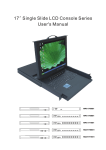
17’’ Dual Slide LCD Console Series
User's Manual
CL-KVM-MPC1700S2-EN
CL-KVM-MPC1700S2-GE
CL-KVM-MPC1700S2-SG
PROGRAM
PC1
PC2
PC3
PC4
PC5
PC6
PC7
PC8
POWER
CL-KVM-MUX1708S2-EN
CL-KVM-MUX1708S2-GE
CL-KVM-MUX1708S2-SG
1u Claxan KVM-Switch Rack
PACKING LIST
CONTENTS:
CL-KVM-MPC1700S2-EN
CL-KVM-MPC1700S2-GE
CL-KVM-MPC1700S2-SG
* 1u 17"Rack-mount Console
* 6ft KVM Cable/Optional
* Back rail for 17.72 " (450mm )~ 31.50 ” (800mm) mounting range
* Power cord
* Philips screws
: 1 pcs
: 1 pcs
: 2 pcs
: 1 pcs
: 8 pcs
Please check to ensure that the unit is not damaged. Report any damages
immediately to your dealer/shipper.
Please read the manual thoroughly and follow the installation and operation
procedures carefully to prevent any damages to the console unit, and/or any devices
connected to it.
I
1u Claxan KVM-Switch Rack
PACKING LIST
CONTENTS:
CL-KVM-MUX1708S2-EN
CL-KVM-MUX1708S2-GE
CL-KVM-MUX1708S2-SG
* 1u 17"Rack-mount Console
* 6ft KVM Cable/Optional
* Back rail for 17.72 " (450mm )~ 31.50 ” (800mm) mounting range
* Power cord
* Philips screws
: 1 pcs
: 8 pcs
: 2 pcs
: 1 pcs
: 8 pcs
Please check to ensure that the unit is not damaged. Report any damages
immediately to your dealer/shipper.
Please read the manual thoroughly and follow the installation and operation
procedures carefully to prevent any damages to the console unit, and/or any devices
connected to it.
II
1u Claxan KVM-Switch Rack
SAFETY INSTRUCTIONS
1.
Please read the manual before installing and operating the console unit.
2.
Please store the user manual in a safe and easily accessible place.
3.
Please power down and unplug the console before performing any cleaning.
4.
No liquid detergent can be applied directly. Use a moist cloth for this purpose.
5.
The unit must be kept in a cool and dry place.
6.
Do not keep the unit in an environment above 140 degree F.
7.
Dropping the unit will cause irreversible damage and/or cause injuries.
8.
Do not block any ventilation holes as the unit will overheat and malfunction.
9.
Make sure that the power rating of the outlet matches the unit's.
10. Plug the unit to a UPS or surge protector to avoid damage thru electrical surges.
11. If in any situation the unit is not used for a long period of time, it is advisable to
power Down and unplug the unit for safety purposes.
12. Place the power in a safe spot to prevent tripping or stepped on.
13. Do not open the unit for any reasons, unless it is done by a qualified technician.
14. Do not pour liquid onto the unit as this can cause a fire or electric shock.
15. All cautions and warnings on the unit must be noted and followed.
16. Before the unit can be use again following any damages to it, a qualified technician
Must test and certify the usability and safety of the unit first.
III
1u Claxan KVM-Switch Rack
INDEXES
PACKING LIST …….…………………………………………………….................…………......................I
SAFETY INSTRUCTIONS………………………………………………………………………..................III
INDEXES……………………………………………………………………………………………...................
SECTION 1 General Information… … … … … … … … … … … … … … … … … … … … … … … … . . . . . . . . . . . . . . . 1
1.1 Overview … … … … … … … … … … … … … … … … … … … … . . …………………................... 1
1.2 Product Specification ( 1PORT)………………………… … … … . . … … . . . . . . . . . . . . . . . . .... . . . 2
1.3 Product Specification (8PORT)………………………………………..…….........................3
SECTION 2 Panel Controls and OSD Functions………………………………………………....................4
2.1 Colour … … … … … … … … … … … … … … … … … … … … … … … … ……....................….....5
2.2 Picture ………………………………………………………………… … . … . . .......................7
2.3 Function ………………………………………………………………………..….....................9
2.4 OSD Menu ……………………………………………………………………………....…...........10
2.5 Misc ………………………………………………………………………...…. . . .....................12
2.6 Exit ……………………………………………………………………...….....................…….13
2.7 Power Indicator (LED light)………………………………………………………………..…..13
SECTION 3 KVM Control and OSD fuction……………………………………………….................. ......14
I FUNCTION …………………………………………………………………….......................... . 1 4
II OPERATION …………………………………………………………………….…......................1 4
1.Front Panel Push Buttons………………………………………………….….......................14
2.Hot-key Commands………………………..................................................................14
3.Using numerical key to select PC………………………..................................................15
4.Press <F1> key to activate the AUTO SCAN function…………………...........................15
5.<F2> key SELECT PC function……………………………............................................ 16
6.<F3> key SEARCH PC function…………………………………………............................17
7.<F4> key EDIT PC NAME function……………………………………..............................18
8.<F5> key MORE SYSTEM function…………………………………….............................20
9.<F6> key EDIT UNIT/PC PSW…………………………………….................................... 21
10.Enable Password………………………..................................................................... 22
11.<F7> enter OSD position adjustable function……………………………........................23
12.<F8> to enter the screen display HELP……………...................................................24
SECTION 4 INSTALLATION ……………………………………………………………….….................... 25
4.1 Preparation for installing the Console into the Cabinet…………………........................25
4.2 Hardware Kit Content ……………………………………………………………................ 25
4.3 Installation for the Console equipped into the Cabinet………………........................ 26
Ċ
1u Claxan KVM-Switch Rack
CHAPTER 1 GENERAL INFORMATION
1.1 Overview
This console is an ideal solution for all network administration environments with
multiple servers and platforms. The 17-inch TFT LCD color display and low-profile
industrial keyboard/touchpad provide the user-friendliest and most reliable
environment for all network administrators. All these functions are integrated into a
17-inch 1u space console. Its rugged construction design also provides space
saving and high reliability for all industrial network applications.
The drawer housing the monitor forms a tough and rugged enclosure that will
protect it from all hazards and also permits easy access to the monitor controls.
The high quality monitor provides flicker-free color images at the optimal
resolutions. It ensures crisp images with clear definitions. This monitor is an autoadjusting and ergonomically designed display.
We utilize the latest in active thin film transistor (TFT) technology for all our
monitors. This provides crisp images and wider viewing angles. Compared with the
conventional CRT, the LCD monitors are not affected by the magnetic fields
commonly found in most plant floor or communications centers. They are also
brighter, making them ideal for high ambient lighting conditions found in today's
factory environments. On-screen menus allow for display adjustments. The
monitor's P-N-P features support Windows 95/98, NT and XP, with the universal
power supply allows global acceptability.
The console's monitor are compatible to most analog RGB (Red, Green, Blue)
display standards, including PS/2, optional for Sun Micro System, Apple Macintosh
Centris, Quadra and Macintosh II Family signals. The monitor is capable of
displaying crisp, vibrant color graphics with VGA, SVGA, XGA ,SXGA, and most
Macintosh compatible color video cards.
1
1u Claxan KVM-Switch Rack
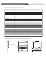
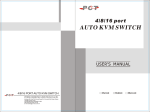
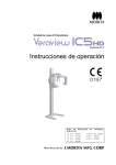
1.2 PRODUCT SPECIFICATIONS(1PORT)
CL-KVM-MPC1700S2-EN \CL-KVM-MPC1700S2-GE \ CL-KVM-MPC1700S2-SG
Function/Model
Ports
1
HD-15M x 1
PC side connector
Console side connector
NO
PC selection method
NO
1280 x 1024@ 60 Hz
Max.Resolution
0.264 (per one triad) x 0.264
Pixel Pitch (mm)
Pixel Position
R.G.B. Vertical Stripe
Display Mode
Normally White
300 (center, Typ) @ 7.5mA
Brightness (cd/m²)
Contrast Ratio
1000:1 (typ.)
Support Color
16.7M colors (RGB 6-bits + FRC data)
Energy Consumption (max.)
24W
Power Supply (External)
110-240V
Power Supply (Internal)
12V 3.8A
Operating temperature
0~45℃
Storage temperature
-20℃~60℃
Housing
Metal
N.W(Kg)/carton
14.2
G.W(Kg)/carton
19.5
Dimensions(mm)
24.41 " (620mm)(L)x17.58 "( 446.4 m m ) (W)x1.72 "( 43.5 m m)(H)
Standards
CL-KVM-MPC1700S2-EN
CE FCC. AC Adaptor: UL, TUV, CE
\CL-KVM-MPC1700S2-GE\CL-KVM-MPC1700S2-SG
136
23
POWER
14.57"(370mm)
24.41"(620mm)
1.72"(43.5mm)
19.02"(483mm)
18.35"(466mm)
1.26"(32.0mm)
24.41"(620mm)~39.17”(995mm)
PC
Num Caps Scroll
Lock Lock Lock
0.08"(2.0mm)
2
1u Claxan KVM-Switch Rack
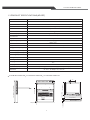
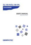
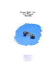
1.3 PRODUCT SPECIFICATIONS(8PORT)
CL-KVM-MUX1708S2-EN \ CL-KVM-MUX1708S2-GE \ CL-KVM-MUX1708S2-SG
Function/Model
Ports
8
HD-15M x 8
PC side connector
8P8C x 1; HD-15F x 1,USB A type x 2(K/B & mouse only)
Console side connector
PC selection method
Hotkey/OSD/Push button
Max.Resolution
1280 x 1024@ 60 Hz
0.264 (per one triad) x 0.264
Pixel Pitch (mm)
Pixel Position
R.G.B. Vertical Stripe
Display Mode
Normally White
300 (center, Typ) @ 7.5mA
Brightness (cd/m²)
Contrast Ratio
1000:1 (typ.)
Support Color
16.7M colors (RGB 6-bits + FRC data)
Energy Consumption (max.)
24W
Power Supply (External)
110-240V
Power Supply (Internal)
12V 3.8A
Operating temperature
0~45℃
Storage temperature
-20℃~60℃
Housing
Metal
N.W(Kg)/carton
14.2
G.W(Kg)/carton
19.5
Dimensions(mm)
24.41 " (620mm)(L)x17.58 "( 446.4 m m ) (W)x1.72 "( 43.5 m m)(H)
Standards
CE FCC. AC Adaptor: UL, TUV, CE
\
CL-KVM-MUX1708S2-EN CL-KVM-MUX1708S2-GE
\CL-KVM-MUX1708S2-SG
136
23
POWER
PC1
PC2
PC3
PC4
PC5
PC6
PC7
PC8
14.57"(370mm)
24.41"(620mm)
1.72"(43.5mm)
19.02"(483mm)
18.35"(466mm)
1.26"(32.0mm)
24.41"(620mm)~39.17”(995mm)
PROGRAM
Num Caps Scroll
Lock Lock Lock
0.08"(2.0mm)
3
1u Claxan KVM-Switch Rack
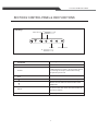
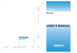
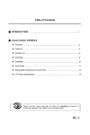
SECTION 2 CONTROL PANEL & OSD FUNCTIONS
Hotkey
Return last menu 50Brightness
50-
+
Contrast
+
Auto-adjustment
Controls
Description
Power
Power On/Off Button. LED will be lit when on.
Status
LED indicator for status. Green means power
on and signal reciept ; Red means standy,
suspend or power off.
Exit
Return last menu
Move cursor up to the function to be adjusted
Move cursor down to the function to be
adjusted
Menu
To access the main menu and also double as
the 'Enter' button
Auto
Auto-adjustment
4
1u Claxan KVM-Switch Rack
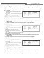
2.1 Color ( To adjust the factors such as contrast, brightness, gamma, colour
temp and color adjust)
2.1.1 Contrast
I. Press the 'Menu' button to activate the on50+
Color
Contrast
screen menu
Picture
Brightness
50+
0
1
2
3
Function
Gamma
II. Use the 'UP' & 'Down' buttons to scroll up or
9300
6500
5800
User
OSD Menu
Color Temp
down
Misc
Color Adjust
III. Scroll down to the selection 'Color'
Exit
Exit
IV. Press the 'Menu' button to confirm the
selection.
V. Use the 'UP' & 'Down' buttons to scroll up or down
VI. Scroll down to the selection 'Contrast'
VII. Press the 'Menu' button to confirm the selection and the number of scale on the right will turn
red from black.
VIII. Use the 'UP' & 'Down' buttons to change the number for contrast adjustment.
2.1.2 Brightness
I. Press the 'Menu' button to activate the on50+
Color
Contrast
Picture
Brightness
screen menu
50+
0
1
2
3
Function
Gamma
II. Use the 'UP' & 'Down' buttons to scroll up or
9300
6500
5800
User
OSD Menu
Color Temp
down
Misc
Color Adjust
III. Scroll down to the selection 'Color'
Exit
Exit
IV. Press the 'Menu' button to confirm the
selection.
V. Use the 'UP' & 'Down' buttons to scroll up or down
VI. Scroll down to the selection 'Brightness'
VII. Press the 'Menu' button to confirm the selection and the number of scale on the right will turn
red from black.
VIII. Use the 'UP' & 'Down' buttons to change the number for Brightness adjustment.
2.1.3 Gamma
I. Press the 'Menu' button to activate the on50+
Color
Contrast
screen menu
Picture
Brightness
50+
0
1
2
3
Function
Gamma
II. Use the 'UP' & 'Down' buttons to scroll up or
9300
6500
5800
User
OSD Menu
Color Temp
down
Misc
Color Adjust
III. Scroll down to the selection 'Color'
Exit
Exit
IV. Press the 'Menu' button to confirm the
selection.
V. Use the 'UP' & 'Down' buttons to scroll up or down
VI. Scroll down to the selection 'Gamma'
VII. Press the 'Menu' button to confirm the selection and the numbers from 0 to 3 on the right are
selectable.
VIII. Use the 'UP' & 'Down' buttons to scroll down to the wanted number( selection) and press
'Menu' button to confirm for Gamma adjustment.
5
1u Claxan KVM-Switch Rack
2.1.4 Color Temperature
I. Press the 'Menu' button to activate the on50+
Color
Contrast
screen menu
Picture
Brightness
50+
II. Use the 'UP' & 'Down' buttons to scroll up or
0
1
2
3
Function
Gamma
9300
6500
5800
User
down
OSD Menu
Color Temp
Misc
Color Adjust
III. Scroll down to the selection 'Color'
Exit
Exit
IV. Press the 'Menu' button to confirm the
selection.
V. Use the 'UP' & 'Down' buttons to scroll up or down
VI. Scroll down to the selection 'Color Temp'
VII. Press the 'Menu' button to confirm the selection and There are 4 options on the right, (9300,
6500, 5800 and User) .
VIII. Use the 'UP' & 'Down' buttons to scroll down to the wanted selection and press 'Menu' button
to confirm for Color Temperature adjustment.
2.1.5 Color adjustment
I. Press the 'Menu' button to activate the on50+
Colour
Contrast
screen menu
Picture
Brightness
50+
0
1
2
3
Function
Gamma
II. Use the 'UP' & 'Down' buttons to scroll up or
9300
6500
5800
User
OSD Menu
Color Temp
down
Misc
Color Adjust
III. Scroll down to the selection 'Color'
Exit
Exit
IV. Press the 'Menu' button to confirm the
selection.
V. Use the 'UP' & 'Down' buttons to scroll up or
50+
Color
Red
down
50+
Picture
Green
VI. Scroll down to the selection 'Color Adjust'
50+
Function
Blue
VII. Press the 'Menu' button to confirm the
OSD Menu
Exit
Misc
selection and the OSD will switch to another
Exit
display mode with 4 options on the right(
Red, Green, Blue colors with scale and
Exit.) .
VIII. Use the 'UP' & 'Down' buttons to scroll down to the wanted color and press the 'Menu' button
to confirm the selection and the number of scale on the right will turn red from black.
VIII. Use the 'UP' & 'Down' buttons to change the number for Color adjustment.
IX. To leave this selection (Color Adjust), use the 'UP' & 'Down' buttons to scroll up or down to
'Exit'
2.1.6 Exit from “ Color” selection
I. To leave this selection, use the 'UP' & 'Down'
buttons to scroll up or down to 'Exit'
II. Press the 'Menu' button to confirm the
selection and move back to the options on the
left.
6
Color
Contrast
50-
Picture
Brightness
50-
Function
Gamma
0
9300
OSD Menu
Color Temp
Misc
Color Adjust
Exit
Exit
+
+
1
2
6500
3
5800
User
1u Claxan KVM-Switch Rack
2.2 Picture ( To adjust the factors such as Horizontal position, Vertical position,
clock and sharpness)
2.2.1 Horizontal position
50+
Color
H.Position
I. Press the 'Menu' button to activate the on50+
Picture
V.Position
screen menu
Function
Phase
50+
II. Use the 'UP' & 'Down' buttons to scroll up or
OSD Menu
Clock
50+
Misc
Sharpness
1
2
3
4
5
down
Exit
Exit
III. Scroll down to the selection 'Picture'
IV. Press the 'Menu' button to confirm the
selection.
V. Use the 'UP' & 'Down' buttons to scroll up or down
VI. Scroll down to the selection 'H.Position'
VII. Press the 'Menu' button to confirm the selection and the number of scale on the right will turn
red from black.
VIII. Use the 'UP' & 'Down' buttons to change the number for Horizontal position adjustment.
2.2.2 Vertical position
I. Press the 'Menu' button to activate the on50+
Color
H.Position
screen menu
50+
Picture
V.Position
II. Use the 'UP' & 'Down' buttons to scroll up or
Function
Phase
50+
Clock
OSD Menu
50+
down
Sharpness
Misc
1
2
3
4
5
III. Scroll down to the selection 'Picture'
Exit
Exit
IV. Press the 'Menu' button to confirm the
selection.
V. Use the 'UP' & 'Down' buttons to scroll up or down
VI. Scroll down to the selection 'V.Position'
VII. Press the 'Menu' button to confirm the selection and the number of scale on the right will turn
red from black.
VIII. Use the 'UP' & 'Down' buttons to change the number for Vertical position adjustment.
2.2.3 Phase
I. Press the 'Menu' button to activate the on50+
H.Position
Color
screen menu
50+
V.Position
Picture
II. Use the 'UP' & 'Down' buttons to scroll up or
Phase
Function
50+
down
Clock
OSD Menu
50+
Sharpness
Misc
1
2
3
4
5
III. Scroll down to the selection 'Picture'
Exit
Exit
IV. Press the 'Menu' button to confirm the
selection.
V. Use the 'UP' & 'Down' buttons to scroll up or down
VI. Scroll down to the selection 'Phase'
VII. Press the 'Menu' button to confirm the selection and the number of scale on the right will turn
red from black.
VIII. Use the 'UP' & 'Down' buttons to change the number for Phase adjustment.
7
1u Claxan KVM-Switch Rack
2.2.4 Clock
I. Press the 'Menu' button to activate the on50+
Color
H.Position
screen menu
50+
Picture
V.Position
II. Use the 'UP' & 'Down' buttons to scroll up or
Function
Phase
50+
OSD Menu
Clock
50+
down
Misc
Sharpness
1
2
3
4
5
III. Scroll down to the selection 'Picture'
Exit
Exit
IV. Press the 'Menu' button to confirm the
selection.
V. Use the 'UP' & 'Down' buttons to scroll up or down
VI. Scroll down to the selection 'Clock'
VII. Press the 'Menu' button to confirm the selection and the number of scale on the right will turn
red from black.
VIII. Use the 'UP' & 'Down' buttons to change the number for Clock adjustment.
2.2.5 Sharpness
I. Press the 'Menu' button to activate the on50+
Color
H.Position
screen menu
50+
Picture
V.Position
Function
Phase
II. Use the 'UP' & 'Down' buttons to scroll up or
50+
Clock
OSD Menu
50+
down
Sharpness
Misc
1
2
3
4
5
III. Scroll down to the selection 'Picture'
Exit
Exit
IV. Press the 'Menu' button to confirm the
selection.
V. Use the 'UP' & 'Down' buttons to scroll up or down
VI. Scroll down to the selection 'Sharpness'
VII. Press the 'Menu' button to confirm the selection and the numbers from 1 to 5 on the right are
selectable.
VIII. Use the 'UP' & 'Down' buttons to scroll down to the wanted number( selection) and press
'Menu' button to confirm for Sharpness adjustment.
2.2.6 Exit from “ Picture” selection
I. To leave this selection, use the 'UP' & 'Down'
buttons to scroll up or down to 'Exit'
II. Press the 'Menu' button to confirm the
selection and move back to the options on the
left.
8
Color
H.Position
50-
+
Picture
V.Position
50-
+
Function
Phase
50-
+
OSD Menu
Clock
50-
Misc
Sharpness
1
Exit
Exit
+
2
3
4
5
1u Claxan KVM-Switch Rack
2.3 Function ( To adjust the factors like Auto colour & Auto adjustment)
2.3.1 Auto Color
I. Press the 'Menu' button to activate the onYES
NO
Color
Auto Color
screen menu
Auto Adjust
Picture
YES
NO
Function
Exit
II. Use the 'UP' & 'Down' buttons to scroll up or
OSD Menu
down
Misc
III. Scroll down to the selection 'Function'
Exit
IV. Press the 'Menu' button to confirm the
selection.
V. Use the 'UP' & 'Down' buttons to scroll up or down
VI. Scroll down to the selection 'Auto Color’
VII. Press the 'Menu' button to confirm the selection and There are 2 options on the right (YES and
NO).
VIII. Use the 'UP' & 'Down' buttons to the wanted selection and press 'Menu' button to confirm. “
NO” to turn off the auto color function and “ YES” to turn on the auto color function.
2.3.2 Auto Adjust
I. Press the 'Menu' button to activate the onYES
NO
Color
Auto Color
screen menu
Picture
Auto Adjust
YES
NO
II. Use the 'UP' & 'Down' buttons to scroll up or
Function
Exit
OSD Menu
down
Misc
III. Scroll down to the selection 'Function'
Exit
IV. Press the 'Menu' button to confirm the
selection.
V. Use the 'UP' & 'Down' buttons to scroll up or down
VI. Scroll down to the selection 'Auto Adjust’
VII. Press the 'Menu' button to confirm the selection and There are 2 options on the right (YES and
NO).
VIII. Use the 'UP' & 'Down' buttons to the wanted selection and press 'Menu' button to confirm. “
NO” to turn off the auto adjustment function and “ YES” to turn on the auto adjustment
function.
2.3.3 Exit from “ Function” selection
I. To leave this selection, use the 'UP' & 'Down'
buttons to scroll up or down to 'Exit'
II. Press the 'Menu' button to confirm the
selection and move back to the options on the
left.
Color
Auto Color
YES
NO
Picture
Auto Adjust
YES
NO
Function
Exit
OSD Menu
Misc
Exit
9
1u Claxan KVM-Switch Rack
2.4 OSD Menu ( To adjust the factors such as Language, OSD Height Position,
OSD Vertical Position, OSD Timer and OSD Translucent.)
2.4.1 Language
Color
Language
I. Press the 'Menu' button to activate the on50+
Picture
OSD
H.POS
screen menu
50+
Function
OSD V.POS
II. Use the 'UP' & 'Down' buttons to scroll up or
NO
OFF
OSD Menu
OSD Timer
down
Misc
Translucent
50+
III. Scroll down to the selection 'OSD Menu'
Exit
Exit
IV. Press the 'Menu' button to confirm the
selection.
Color
English
Italiano
V. Use the 'UP' & 'Down' buttons to scroll up or
繁 中文
Picture
Francais
,
down
简体中文
Function
Dautsch
VI. Scroll down to the selection 'Language'
日本语
OSD Menu
Espanol
~
VII. Press the 'Menu' button to confirm the
Misc
selection and the OSD will switch to another
Exit
display mode with 8 options of languages
on the right( Including English, Franch,
Deutsch, Spanish, Italian, Traditional Chinese, Simplified Chinese and Japanese) .
VIII. Use the 'UP' & 'Down' buttons to scroll down to the wanted language and press the 'Menu'
button to confirm the selection.
2.4.2 OSD Height Position
I. Press the 'Menu' button to activate the onColor
Language
screen menu
50+
Picture
OSD H.POS
II. Use the 'UP' & 'Down' buttons to scroll up or
50+
Function
OSD V.POS
down
NO
OFF
OSD Menu
OSD Timer
Misc
Translucent
50+
III. Scroll down to the selection 'OSD Menu'
Exit
Exit
IV. Press the 'Menu' button to confirm the
selection.
V. Use the 'UP' & 'Down' buttons to scroll up or down
VI. Scroll down to the selection 'OSD H.Pos'
VII. Press the 'Menu' button to confirm the selection and the number of scale on the right will turn
red from black.
VIII. Use the 'UP' & 'Down' buttons to change the number for OSD Height Position adjustment.
2.4.3 OSD Vertical Position
I. Press the 'Menu' button to activate the onColor
Language
screen menu
50+
Picture
OSD H.POS
II. Use the 'UP' & 'Down' buttons to scroll up or
50+
Function
OSD V.POS
down
NO
OFF
OSD Menu
OSD Timer
III. Scroll down to the selection 'OSD Menu'
Misc
Translucent
50+
Exit
Exit
IV. Press the 'Menu' button to confirm the
selection.
V. Use the 'UP' & 'Down' buttons to scroll up or down
VI. Scroll down to the selection 'OSD V.Pos'
VII. Press the 'Menu' button to confirm the selection and the number of scale on the right will turn
red from black.
VIII. Use the 'UP' & 'Down' buttons to change the number for OSD Vertical Position adjustment.
10
1u Claxan KVM-Switch Rack
2.4.4 OSD Timer
I. Press the 'Menu' button to activate the onColor
Language
screen menu
50+
Picture
OSD H.POS
II. Use the 'UP' & 'Down' buttons to scroll up or
50+
Function
OSD V.POS
NO
OFF
OSD
Menu
OSD
Timer
down
Translucent
Misc
50+
III. Scroll down to the selection 'OSD Menu'
Exit
Exit
IV. Press the 'Menu' button to confirm the
selection.
Color
Language
V. Use the 'UP' & 'Down' buttons to scroll up or
50+
Picture
OSD H.POS
down
50+
Function
OSD V.POS
VI. Scroll down to the selection 'OSD Timer'
50+
OSD Menu
OSD Timer
Misc
Translucent
50+
VII. Press the 'Menu' button to confirm the
Exit
Exit
selection and There are 2 options on the
right (ON & OFF). .
VIII. Use the 'UP' & 'Down' buttons to the wanted selection and press 'Menu' button to confirm. “
ON” to turn on the OSD Timer function and “ OFF” to turn off the OSD Timer function
VII. Turn on the OSD Timer function and a scale would show up. Use the 'UP' & 'Down' buttons to
change the number for OSD Timer adjustment. The unit is in second.
2.4.5 OSD Translucent
I. Press the 'Menu' button to activate the onColor
Language
screen menu
50+
Picture
OSD H.POS
II. Use the 'UP' & 'Down' buttons to scroll up or
50+
Function
OSD V.POS
NO
OFF
OSD Menu
OSD Timer
down
Misc
Translucent
50+
III. Scroll down to the selection 'OSD Menu'
Exit
Exit
IV. Press the 'Menu' button to confirm the
selection.
V. Use the 'UP' & 'Down' buttons to scroll up or down
VI. Scroll down to the selection 'Translucent'
VII. Press the 'Menu' button to confirm the selection and the number of scale on the right will turn
red from black.
VIII. Use the 'UP' & 'Down' buttons to change the number for OSD Translucent adjustment.
2.4.6 Exit from “ OSD Menu” selection
I. To leave this selection, use the 'UP' & 'Down'
buttons to scroll up or down to 'Exit'
II. Press the 'Menu' button to confirm the
selection and move back to the options on the
left.
11
Color
Language
Picture
OSD H.POS
50-
Function
OSD V.POS
50-
OSD Menu
OSD Timer
NO
Misc
Translucent
50-
Exit
Exit
+
+
OFF
+
1u Claxan KVM-Switch Rack
2.5 Misc ( To adjust the factors of Mode Select and reset function.)
2.5.1 Mode Select
I. Press the 'Menu' button to activate the onMode Select
Color
640×4 0 0
7 2 0×4 0 0
screen menu
Reset
Picture
YES
NO
II. Use the 'UP' & 'Down' buttons to scroll up or
Exit
Function
OSD Menu
down
Misc
III. Scroll down to the selection 'Misc'
Exit
IV. Press the 'Menu' button to confirm the
selection.
V. Use the 'UP' & 'Down' buttons to scroll up or down
VI. Scroll down to the selection 'Mode Select’
VII. Press the 'Menu' button to confirm the selection and The 2 options, 640x 400 and 720x400 are
selectable.
VIII. Use the 'UP' & 'Down' buttons to scroll down to the wanted selection and press 'Menu' button
to confirm for Mode Select adjustment.
2.5.2 Reset
I. Press the 'Menu' button to activate the onColor
Mode Select
640×400
720×400
screen menu
Picture
Reset
YES
NO
Function
Exit
II. Use the 'UP' & 'Down' buttons to scroll up or
OSD Menu
down
Misc
III. Scroll down to the selection 'Misc'
Exit
IV. Press the 'Menu' button to confirm the
selection.
V. Use the 'UP' & 'Down' buttons to scroll up or down
VI. Scroll down to the selection 'Reset'
VII. Press the 'Menu' button to confirm the selection and There are 2 options on the right (YES and
NO).
VIII. Use the 'UP' & 'Down' buttons to the wanted selection and press 'Menu' button to confirm. “
NO” is no any effects or changes on current operation. “ YES” to turn back to default setting.
2.5.3 Exit from “ Misc” selection
I. To leave this selection, use the 'UP' & 'Down'
buttons to scroll up or down to 'Exit'
II. Press the 'Menu' button to confirm the
selection and move back to the options on
the left.
Color
Mode Select
640×400
Picture
Reset
YES
Function
Exit
OSD Menu
Misc
Exit
12
NO
720×400
1u Claxan KVM-Switch Rack
2.6 Exit ( To exit ouit of the main Menu)
Color
Select the 'Exit' button and press ' Menu' to exit
the OSD Menu
Picture
Function
OSD Menu
Misc
Exit
2.7 Power Indicator( LED light )
I. Green
II. Red
III. Red
IV. Red
ON
Standby
Suspend
Off
13
1u Claxan KVM-Switch Rack
SECTION 3 KVM Control and OSD function
I.
FUNCTION
1. This operation manual is adapted to Auto Multi-PCs Controller which are available with OSD
(ON SCREEN DISPLAY) support. This series of model can be connected as a first level of a
MASTER unit in cascade configuration.
2. When multi models are cascaded, the one which has a mouse, a keyboard and a monitor
connected to its Console port directly and operated by a user called “MASTER”; other
cascaded models are called “SLAVE”. The console side of each SLAVE has to be connected
to the PC side of MASTER.
3. For these models with built-in OSD (ON SCREEN DISPLAY) control, user can easily be
aware of the system status and operations through on screen menu.
4. These series of models can set up individual PC name and search the PC by name.
5. Password setup and management are available. If the password is built, you must input the
correct password to access the target PC.
6. AUTO SCAN function is available, Scan time interval is adjustable.
II. OPERATION
1. Front Panel Push Buttons
A. Selecting the PC by pressing the front panel push button directly.
B. The Auto Scan button of SLAVE will be disable when in cascade configuration.
2. Hot-key Commands
A. HOT-KEY can be set as <SCROLL > key (original design) or <L-CTRL> (LEFT CTRL)
Key.
B. Press HOT-KEY twice (Within 3 seconds) (Remark: Press HOT-KEY only one time when
password is accepted), then into the HOT-KEY MAIN MENU mode.
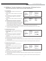
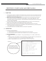
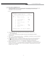
C. When on MAIN MENU screen, the OSD display is shown as Figure(1):
Figure(1)
The currently in Use PC
is connected to the Port 7
of SLAVE and this SLAVE
is cascaded to the MASTER
PC:3+7
MAIN MENU
───────────────────────
F1 AUTO. SCAN MODE
F2 SELECT PC
F3 SEARCH PC NAME
F4 EDIT PC NAME
F5 MORE SYSTEM
F6 EDIT UNIT/PC PSW.
F7 OSD POSITION
F8 HELP
PRESS ESC TO EXIT
14
1u Claxan KVM-Switch Rack
.
D. Line one shows PC:3+7 which indicates that the currently in use PC is connected to the
port 7 of SLAVE and this SLAVE is cascaded to the MASTER port 3.
E. Under this screen mode, user can press button<F1>, <F2>, <F3>, <F4>, <F5>, <F6> for
Activating its function and can also press number key (0-9) to select PC.
F. While activating the HOT-KEY commands, MOUSE will be disable temporarily,
KEYBOARD can only control the OSD screen but CANNOT control the selected PC
G. Press <ESC> to exit the MAIN MENU screen and return to the PC operation, the
MOUSE and KEYBOARD can then work normally.
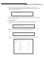
3. Using numerical key to select PC
A. Press the numerical key once and the screen sill show as Figure(2), then press 0-9 to
select PC.
B. The port number which is connected to the MASTER should be input first and following
press <+> and then press the port number of the SLAVE which is connected to the
Selected PC.
C. Hit <ENTER> to confirm. You can access the selected PC immediately if it is powered on.
D. If the selected PC has not been powered on, OSD shows “DISABLE”.
E. If selected wrong PC number, OSD displays “ERROR”.
Figure(2)
SELECT PC:?
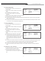
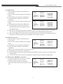
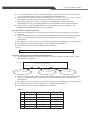
4.Press<F1>key to activate the AUTO SCAN function
A. In MAIN MENU,hitting<F1>key is to indicate to enter into AUTO SCAN function ,OSD
Will display as Figure(3).
Figure(3)
A U TO SCAN
PC: 3+9
12345678
P C o f M ASTR
PC of SLAVE
PC NAME
B. The port number which is connected to the MASTER should be input first and following
press <+> and then press the port number of the SLAVE which is connected to the
Selected PC.
C. Hit <ENTER> to confirm. You can access the selected PC immediately if it is powered on.
D. If the selected PC has not been powered on, OSD shows “DISABLE”.
E. If selected wrong PC number, OSD displays “ERROR”.
Table(1)
Sec.
5
10
15
20
25
30
NUM LOCK
OFF
ON
ON
OFF
OFF
ON
CAPS LOCK
OFF
OFF
OFF
ON
ON
ON
15
SCROLL LOCK
ON
OFF
ON
OFF
ON
OFF
1u Claxan KVM-Switch Rack
F. Under AUTO SCAN mode, hitting<→> key is to select the nest powered-on PC.
G. Under AUTO SCAN mode, hitting<←> key is to select the previous powered-on PC.
H. Exit Auto SCAN mode:
Press <ESC> key to exit the AUTO SCAN and return to the selected PC and also enter
into the MENU mode operation, and the MOUSE and KEYBOARD then work normally.
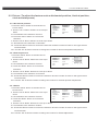
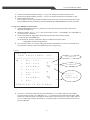
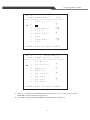
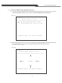
5. <F2> key SELECT PC function
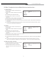
A. Under MAIN MENU mode, hit <F2>key to enter the select PC function, the screen
displays as Figure(4).
B. Under the mode, use <↓> or <↑> key to move the cursor ☞(CURSOR), use <ENTER> to
Confirm the PC selection.
C. Under OSD display: right side (STU) field shows the selected PC status:
+ :selected PC is POWER ON;
+ 8:selected PC is daisy-chained to 8 port model series which have
MASTER / SLAVE Configuration.
D. Line one shows PC: 3+7 which indicates that the selected PC is Port 7 of SLAVE and
This SLAVE is daisy-chained to MASTER port 3. (Figure(4))
Figure(4)
PC:3+7
PORT SELECT MENU
STU
───────────────────────
1
PC1-1111
2
PC2-2222
3
SLAVER-3
4
PC4-4
5
PC5-5555
6
PC6
7
SLAVER-7
8
PC8
+
+8
+
+8
PC POWER OFF
PC POWER ON
PC side is
connected
to
SLAVE of 8port
PRESS ESC TO MAIN MENU
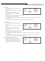
E. If cursor☞ selects the PC which is remarked with “⊕ò” means that the PC is daisyChained to the SLAVE. Hit <ENTER> or <→> to enter into the cascaded SLAVE. OSD
shows the selected daisy-chained PC information (see Figure(5)). On the right side of
Line 1 of Figure(5) shows “SLAVER:??” to identity the on screen information is from??
Port of SALVER.
16
1u Claxan KVM-Switch Rack
PC : 3 + 7
S L AVER: 3
P O R T S E L E C T M ENU
STU
─── ─ ─ ─ ─ ─ ─
─ ─ ─ ─ ─ ─────────
1
S3-PC111
2
S3-PC222
3
EMAIL-1
4
SMPT-3
5
S3-PC555
6
S3-PC6
7
S3-PC7
8
S3-PC8
+
+
Presents the OS D
screen informat i o n
is from SLAVE 3
+
+
PR E S S E S C T O M AIN MENU
F. Shown SLAVE PC information as Figure(5), press <←> to return to the MASTER PC
(Shown as Figure(4)).
G. Press <ESC> key to come back to MAIN MENU (Shown Figure(1)).
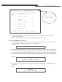
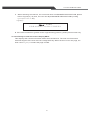
6. <F3> key SEARCH PC function
A. On MAIN MENU screen mode, press <F3> to enter into PC NAME input mode to search
For the target PC, OSD message shown as FIGURE(6).
FIGURE(6)
SEARCH
NAME : ?
B. Input at most 16 characters ( <A~Z>, numerical <0~9> and <-> etc) and press <ENTER>
as confirmation. For example: input <PC12345> and hit <ENTER> to start searching the
target PC <PC12345>. When targeted PC is found, it will switch to the PC autocratically.
C. If no PC NAME is matched, the OSD will display “ERROR” message (shown as Figure(7)).
FIGURE(7)
ERROR
SEARCH NAME : PC12345
D. If the searched PC is powered off, the OSD will display “DISABLE” message (shown as
Figure(8)).
Figure(8)
DISABLE
PC : 12 + 5 – PC12345
17
1u Claxan KVM-Switch Rack
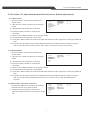
7. <F4> key EDIT PC NAME function
A.
Under MAIN MENU mode: hit <F4> key to enter the edit PC name operation (shown as
Figure(9)), on the Line 1 of Figure(9) show PC : 2 indicating the current screen
Information is from the second PC.
Figure(9)
PC:2
PORT NAME EDIT
STU
─ ─ ─ ─ ─ ─ ─ ─ ── ─ ─ ─ ─ ─ ─ ─ ─ ─ ─ ─ ─ ─
1
PC1-1111
2
P C2 - 2 2 2 2
3
S LA V E R - 3
4
P C4 - 4
5
P C5 - 5 5 5 5
6
P C6
7
S LA V E R - 7
8
P C8
+
+8
+
+8
P R E S S ES C T O M A I N M EN U
B. Under OSD mode: on the right side of (STU) field show the status of PC:
+ : PC is POWER ON;
+ 8: PC is daisy-chained to 8 port model series which have MASTER / SLAVE
Configuration.
C. use <↓> or <↑> key to move the cursor ☞(CURSOR), hit <ENTER> to enter the edit PC
name operation (shown as Figure(10)).
D. In Figure(10) the cursor☞ indicates to edit the name of PC2. the cursor becomes the
icon■ prompt to indicate the location you are editing. Input at most 16 characters
(<A~Z>, numerical <0~9> and <-> etc) and press <ENTER> as confirmation.
E. Edit SLAVE PC name: use <↓>, <↑>, <Page Up>, <Page Down> to select the PC of
SLAVE. Then press <→> to select the daisy-chained SLAVE PC, the OSD screen shows
as Figure (11): the right side of Line 1 shows “SLAVER:3” indicating the current screen
Display is from ?? SLAVE.
18
1u Claxan KVM-Switch Rack
PC:2
P O R T N A ME EDIT
STU
───────
─ ─ ──────────────
1
P C 1-1111
2
3
S L AVER-3
4
P C 4-4
5
P C 5-5555
6
PC6
7
S L AVER-7
8
PC8
+
+8
+
+8
P R E S S E S C TO MAIN MENU
Figure(10)
PC:2
SLAVER: 3
PORT NAME EDIT
STU
───────────────────────
1
S3-PC111
2
S3-PC222
3
EMAIL-1
4
SMPT-3
5
S3-PC555
6
S3-PC6
7
S3-PC7
8
S3-PC8
+
+
+
+
PRESS ESC TO MAIN MENU
Figure(11)
F. Figure (11) shows the selected SLAVE PC information; hit <←> key to return to the
MASTER PC mode (shown as Figure(9)).
G. Hit <ESC> to back to the MAIN MENU mode (shown as Figure (1)).
19
1u Claxan KVM-Switch Rack
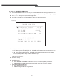
8. <F5> key MORE SYSTEM function
A. Under MAIN MENU mode: hit <F5> key to enter the MASTER PC setting operations. You
Can hit <↓> or <↑> or <←> or <→> key to setup these parameters.(shown as Figure (12))
B. Hit <↓> or <↑> key to move cursor and select item.
C. Hit <←> or <→> key to change the setting.
D. Hit <ESC> to go back to the MAIN MENU (Figure (1)) shown as follow:
Figure (12)
PC:3+7
MORE SYSTEM
───────────────────────
POWER ON SCAN
OFF
SCAN TIME
5 SEC
HOT-KEY
SCROLL
BUZZER
ON
BACKGROUND COLOR
ON
↓ ↑ FOR SELECT
? ? FOR SET
PRESS ESC TO MAIN MENU
E. POWER ON SCAN setup:
a. OFF after resetting the MASTER PC, POWER ON SCAN will search and switch to the
PC which is power on directly.
b. ON After resetting MASTER PC, POWER ON SCAN will activate the AUTO SCAN
Function, the operation step is same as above step 4.
F. SCAN TIME setup:
Same as {4-E}Table(1).
G. HOT-KEY setup:
Two choices - <SCROLL> and <L-CTRL>.
H. BUZZER setup:
a. OFF BUZZER is DISABLE while hitting HOT-KEY and front panel push button.
b. ON BUZZER is ENABLE while hitting HOT-KEY and front panel push button.
I. BACKGROUND COLOR setup:
a. OFF No background color
b. ON the background color is light -blue
20
1u Claxan KVM-Switch Rack
9. <F6> key EDIT UNIT/PC PSW
A. Password setting: MASTER Password and PC side Password.
a. MASTER Password:
Controlling and Editing the MASTER password. When user
enters the HOT-KEY mode, hit <F6> to edit password. OSD will ask for the correct
password of MASTER (shown as Figure(13)). After entering the correct password, user
Are allowed to use the device.
Figure(13)
UNIT PS W . : ?
b. PC Password:
Controlling the operation of PC side. User will be asked for the password, only when the
password id entered correctly will the user be allowed to use this PC. OSD screen shown
as Figure (16).
B. Under MAIN MENU mode: hit <F6> key for password editing and if the MASTER
password function has been already set, the OSD will ask for entering the password of
MASTER (as Figure(13)). Only when the password is entered correctly will the user be
Allowed to use this device, OSD Shown as Figure(14).
Figure(14)
PC:2
EDIT UNIT OR PORT
───────────────────────
1 EDIT UNIT PSW.
2
EDIT PC PORT PSW.
PRESS ESC TO MAIN MENU
C. Under MAIN MENU mode: hit <F6> key for password editing. If the password function of
MASTER is not set yet (UNIT PSW.) ,you can deit new password directly (OSD screen
shown as Figure(14)).
D. Enter Editing function shown as Figure(14)
a. Editing MASTER password (EDIT UNIT PSW.)
b. Editing PC password (EDIT PC PORT PSW.) including editing the PC password of
SLAVE.
21
1u Claxan KVM-Switch Rack
E. Select 1 means to EDIT UNIT PSW. : Editing MASTER password, OSD will show as
Figure(15), user should type 1-8 characters (valid characters are <A-Z>, <0-9> and <->)
as the new password of MASTER and then press <ENTER> as confirmation. User should
Keep the new password firmly in mind.
Figure(15)
NEW PSW.:?
F. Select 2 to EDIT PC PORT PSW. : OSD will show as Figure(15). User can use <↓> or <↑>
to move ☞(CURSOR) and press <ENTER> to select PC. The procedure of PC password
Edition is same as step 6.
10. Enable Password:
A. If selected PC has setup the password. OSD will ask for entering the password of the PC,
(Shown as Figure (16)). Correct password is required to use the selected PC.
Figure(16)
P C P A S SWORD:?
P C : 1 2 + 5 - PC12345
B. When user enter the wrong password, the OSD will show message “ ERROR” (Shown as
Figure(17)). User will be asked for re-entering the correct password.
Figure(17)
ERROR
PC:12+5 - PC12345
C. Under Figure (16) mode, user can hit HOT-KEY once to enter HOT-KEY MAIN MENU.
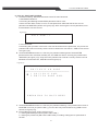
Figure(18)
PC:2
PORT PSW. EDIT
STU
───────────────────────
1
PSW1
+
+8
2
PSW2
3
PSW3
4
PSW-4
5
PSW-5555
6
PSW6
7
PSW7
8
PSW8
+
+8
PRESS ESC TO MAIN M E N U
22
1u Claxan KVM-Switch Rack
11. <F7> enter OSD position adjustable function
A. There are 2 kinds of OSD screen display adjustable, please refer to Figure(19). One is to
adjust MAIN OSD POSITION. The other is to adjust BANNER OSD POSITION.
Figure(19)
PC:2
OSD POSITION
───────────────────────
1 MAIN OSD POSITION
2 BANNER OSD POSITION
PRESS ESC TO MAIN MENU
B. After selecting the choice 1, the screen will enter into MAIN OSD POSITION, please refer
to Figure(20).By then, the user can adjust MAIN OSD POSITION by hitting
<↓>/<↑>/<←>/<→> key.
Figure(20)
PC:2
M A I N O SD P O S I T I O N
───────────────────────
UP
LEFT
TO MOVE
R IG H T
DOWN
P R E S S ES C T O M A I N M E N U
23
1u Claxan KVM-Switch Rack
C. When selecting the choice 2, the screen will enter into BANNER OSD POSITION, please
refer to Figure(21). By then, the user can adjust BANNER OSD POSITION by hitting
<↓>/<↑>/<←>/<→> key.
Figure(21)
:TO MOV E
P R E S S E SC TO MAIN MENU
D. If the user would like to go back to the original setting position, please press<Home> key
12. Hit <F8>key to enter the screen display HELP
This displays the contact information about the manufacturer. The user can find instant
technical support if the user met some usage difficulty. When the text is over one page, the
User can hit <↓>/<↑> to select the page needed.
24
1u Claxan KVM-Switch Rack
SECTION 4 INSTALLATION
4.1 Preparation for installing the Console into the Cabinet
I.
II.
III.
IV.
Make sure that all the accessories are present according to the list.
Make sure that the main console unit is not damaged.
Make sure that equipment is powered off.
For standard rack-mounts, the shorter brackets are required.
4.2 Hardware Kit Content
I.
Back rail for 17.72 " (450mm)~31.5 " (800mm) mounting range.
III.
Philips screws x 8(For mounting rail to Console unit)
25
1u Claxan KVM-Switch Rack
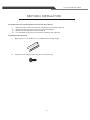
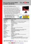
4.3 Installation for the Console equipped into the Cabinet
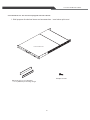
I. Well prepare the below items and accessories.(see below pictures)
LCD Consle unit
Philips screws
Back rail for 17.72 " (450mm )
~ 31.5 " (800mm) mounting range.
26
1u Claxan KVM-Switch Rack
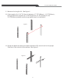
II. Measure the length of A . See figure 1.
III. If the length of A+ 0.14 " (3.5mm) is between 17.72 " (450mm )~ 31.5 " (800mm) ,
then get the short support ear. If the length of A+ 0.14 "( 3.5mm ) is over
31.5 "( 800mm ) , please use the long support rear for Installation.
Figure 1
A
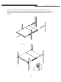
IV. Screw the back rail which would be fixed with LCD console unit to the proper
Position of the rackrail of the cabinet. See figure 2
Figure 2
27
1u Claxan KVM-Switch Rack
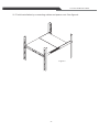
V. Install the LCD console by inserting the guide of the unit( both side of LCD
console unit) into the 2 back rails. And push the console to the end of back and
screw the front rail to the proper position of the rackrail of the cabinet. See
Figure 3
Figure 3
28
1u Claxan KVM-Switch Rack
VI. Finish installation by connecting cables and power cord. See figure 4.
Figure 4
29