1
A2320
Display Enhancer Board
User's Manual
Copyright © 1990 by Commodore Electronics Limited. All Rights Reserved. This document may not, in
whole or in part, be copied, photocopied, reproduced, translated, or reduced to any electronic medium or
machine readable form, without prior consent, in writing, from Commodore Electronics Limited.
With this document, Commodore makes no warranties or guarantees, either express or implied, with respect to
the products described, their functionality, compatibility, or availability. Further, Commodore assumes no
responsibility or liability for statements or representations made by itself or by third party vendors or in the
publications represented herein. IN NO EVENT WILL COMMODORE BE LlABLE FOR DIRECT,
INDIRECT, INCIDENTAL, OR CONSEQUENTIAL DAMAGES RESULTING FROM ANY CLAIM
ARlSING OUT OF THE REPRESENTATIONS MADE HEREIN, EVEN IF IT HAS BEEN ADVISED OF
THE POSSIBILITIES OF SUCH DAMAGES. SOME STATES DO NOT ALLOW THE EXCLUSION OR
LIMITATION OF SUCH WARRANTIES OR DAMAGES, SO THE ABOVE EXCLUSIONS OR
LIMITATIONS MAY NOT APPLY.
Information in this document is subject to change without notice and does not represent a commitment on the
part of Commodore. Commodore and the Commodore logo are registered trademarks of Commodore
Electronics Limited. Amiga is a registered trademark of Commodore-Amiga, Inc.
Diamond Scan and Multivision are trademarks of Mitsubishi Electronics and Taxan USA, respectively.
MultiSync is a registered trademark of NEC Technologies, Inc.
NOTICE: This device complies with Part 15 of the FCC Rules and Standard C108.8-M1983 of the Canadian
Standards Association Regulations. Operation is subject to the two conditions: (1) This device may not cause
harmful interference, and (2) this device must accept any interference received including interference that may
cause undesired operation. If you suspect this device is causing interference, you can test this device by
turning it off and on. If this device does cause interference, the user is encouraged to correct the interference
by one of the following means:
•
Reorient the receiving antenna or AC plug.
•
Change the relative positions of the computer with respect to the receiver.
•
Plug the computer into a different outlet so the computer and receiver are on different
branch circuits.
CAUTION: Only peripherals with shielded-ground cables (computer input-output devices, terminals, printers,
etc.) certified to comply with Class B limits can be attached to this device. Operation with non-certified
peripherals may result in communications interference. Changes or modifications to this device not expressly
approved by the party responsible for compliance could void the user's authority to operate this equipment.
Your house AC wall receptacle must be a three-pronged type (AC ground). If it is not, contact an electrician to
install the proper receptacle. If a multi-connector box is used to connect the computer and peripherals to AC,
the ground must be common to all units.
If necessary, the user should consult the dealer or an experienced radio-television technician for additional
suggestions. The user may find the following booklet prepared by the Federal Communications Commission
helpful: "How to Identify and Resolve Radio-TV Interference Problems." This booklet is available from the
U.S. Government Printing Office, Washington, D.C. 20402. Stock No. 004-000-00345-4.
If this product is being acquired for or on behalf of the United States of America, its agencies and/or
instrumentalities, it is provided with RESTRICTED RIGHTS, and all use, duplication, or disclosure with
respect to the included software and documentation is subject to the restrictions set forth in subdivision
(b) (3) (ii) of the Rights in Technical Data and Computer Software clause at 252.227-7013 of the DOD FAR.
Unless otherwise indicated, the manufacturer/integrator is Commodore Business Machines, Inc., 1200 Wilson
Drive, West Chester, PA 19380.
Table of Contents
1. Introduction
A2320 Display Enhancer Main Features
2. How to Install the A2320 Display
Enhacer Board
1
1
3
Removing the Amiga's Cover
3
Installing the A2320
4
Connecting the Multiscan Monitor
8
3. Adjusting the A2320's Fine Tuning
Control
Adjustment Procedure
9
9
Standard Chipset and AmigaDOS 1.3
10
ECS and AmigaDOS 2.0
10
4. Operation and Compatibility
13
ECS Compatibility
13
External Genlock Compatibility
14
Software Compatibility
15
Monitor Compatibility
15
Using the A2320 in NTSC and PAL Systems
15
5. Troubleshooting
17
General Troubleshooting
17
Coarse and Fine Tuning Adjustment
19
Appendix A: Theory of Operation
21
Background Information
21
A2320 Display Enhancer Basic Building Blocks
23
Appendix B: Technical Specifications
Video Connector Pinout
25
26
1.
Introduction
The A2320 Display Enhancer board for the Commodore Amiga 2000
family of personal computers provides an alternate video display output
that yields an image with no flicker or visible scan lines in interlaced or
non-interlaced Amiga graphics modes. The solid, flicker-free output of the
A2320 is ideal für Amiga applications requiring the crispest, most
professional high-resolution color display possible.
The A2320 board is intended to be compatible with existing software and
internal Amiga plug-in boards (except other boards that occupy the Video
slot), as well as the new ECS 'Productivity' and 'Superhires' modes
available under AmigaDOS™ 2.0. The board can also function with many
external genlocks, providing flicker-free reference display of Amiga
graphics during video work. And the A2320 Display Enhancer
significantly augments the graphics presentation potential of the Amiga
for business applications of the Amiga 2000.
A2320 Display Enhancer Main Features
• Employs de-interlacing in Amiga interlaced display modes to remove
flicker and visible scan lines with full overscan support for both
NTSC and PAL Amiga modes. This is achieved by a custom gate
array and 1-Mbit CMOS digital video field memories.
• Employs scan-doubling in Amiga non-interlaced display modes to
remove visible scan lines WITHOUT motion artifacts.
• Severe overscan support.
• Compatible with both NTSC and PAL Amiga video formats.
• Supports the new ECS display modes, such as Productivity mode,
under AmigaDOS 2.0. The A2320 Display Enhancer board
automatically detects Productivity mode and responds accordingly
(see Chapter 4.)
1
• A mode switch is provided to allow bypassing of the de-interlaced or
scan-doubled video for output of the original Amiga video to the
multiscan monitor. This is used to display the ECS Superhires mode
(1280 X 200/256 or 1280 X 400/512) on the monitor.
• A2320 output is not interfered with by many external genlocks
(NTSC or PAL), providing high-resolution, flicker-free display of
Amiga-only RGB graphics.
• Transparent to software.
• Video output is compatible with standard multiscan (multisync)
VGA monitors and provides a standard female DB 15 VGA-style
connector.
• An Amiga monitor (1084, 1084S, 1080, 2002) or external composite
encoder box (A520) can remain attached to the Amiga's 23-pin RGB
port, providing a standard video display.
• Fully supports the Amiga's 4096-color palette and HAM (hold-andmodify) modes.
• Plugs into the video slot of the Amiga and does not sacrifice any of
the Amiga bus slots.
2
2.
How to Install the A2320
Display Enhancer Board
WARNING: Unplug your Amiga before installing the A2320. Installing the
A2320 with the power connected could cause injury to the installer and
damage to the equipment.
Commodore will not be responsible for any damages caused by improper
installation of the A2320. Such improper installation will void the warranties
on both the A2320 and the Amiga. It is recommended that installation of
internal expansion boards be handled by an Authorized Commodore Service
Center.
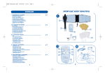
Before beginning, make sure that the following items have been received:
• A2320 Display Enhancer Board in anti-static bag
• plastic alignment tool
• Grounding clip (for countries that require it)
• A2320 Test/Demo disk
• A2320 User's Manual and Warranty card
If any of the above items are missing please contact the dealer from whom you
purchased the A2320 Display Enhancer Board.
NOTE:
Except where otherwise indicated, throughout this manual references to "left" and
"right" should be understood to be as you face the front of the machine.
Removing the Amiga's Cover Tools needed: Phillips-head screwdriver
To install the A2320, you must first make sure the Amiga is OFF. Disconnect the
mouse and keyboard from the front of the Amiga,
3
and remove the power cord and any peripherals attached to the back of the
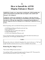
machine. On the lower left side of the Amiga, remove the two screws that hold the
metal cover to its base. Remove the corresponding screws on the right side of the
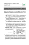
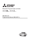
Amiga. Remove the Center screw from the rear of the Amiga. Be careful to
remove the correct screw as shown (see Fig. 1.)
Fig. 1: A2000 - Rear View
Turn the Amiga so that you are facing the front of the machine. Grasp the cover on
both sides, slide it toward you, and lift upward. If the cover gets stuck, do not force
it. Look under the top of the cover toward the middle and check to see if any wires
or cables are caught under the tab to which the middle screw had been attached. If
anything is caught, gently untangle it, and continue to slide the cover off.
Installing the A2320 Before installing the A2320, you must first determine whether your Amiga 2000
has a 2- or 4-layer motherboard. The A2320 can ONLY be used with the 2-layer
motherboard version of the Amiga 2000. This is determined by looking at the
front left-hand corner of the motherboard. You should find, on the left edge of the
motherboard, a label which says "AMIGA B2000 - CR" which indicates that your
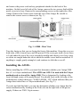
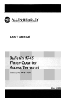
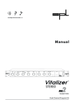
Amiga does indeed have a 2-layer motherboard. (See Fig. 2.)
If you do not find this label, you can also determine whether your Amiga has the
correct motherboard by looking at the Video slot on the right side of the power
supply. If there are TWO 36-pin connec-
4
Fig. 2: A2000 - Top View
tors on the motherboard then your Amiga has a 2-layer motherboard and you may
continue with the installation procedure. If there is only one 36-pin connector there
you should consult an authorized Commodore service center for a replacement of
your motherboard with the newer 2-layer version.
The A2320 is installed in the Video slot on the right side of the power supply.
Turn the Amiga so that you face the rear panel of the computer and locate the
Video slot cover plate which is just to the left of the power switch. Remove the
screws that hold the metal plate in place and lift it out. Save the screws; you'll need
them for installation of the A2320 board.
5
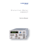
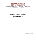
If a copper grounding clip, shaped like a "U", is included with your A2320, install it
as follows. Measure out from the front end of the power supply 1.5 inches along the
right side of the disk drive tray (as you face the front of the A2000) and slip the
grounding clip over the edge of the tray such that the fingers of the clip are toward
the right side of the A2000 and the open end of the clip is facing up (see Fig. 3).
Note that on the back of the A2320 board there is a cut-out in the insulation sheet
and a bare area on the board itself. For proper grounding, ensure that the grounding
clip is touching the bare area on the board.
Fig. 3: Copper Grounding Clip
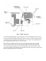
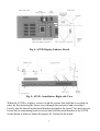
Remove the A2320 board (Fig. 4) from its protective anti-static bag and orient the
board so that the bracket and connectors are toward the rear of the machine with the
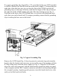
IC chips facing away from the power supply (see Fig. 5). Align the A2320 board
above the video slot connectors with the metal bracket against the inside rear panel
of the computer and the DB 15 monitor connector and mode switch poking through
the rear panel opening. Applying gentle pressure, insert the board into the two slots
until you feel the board seat firmly.
6
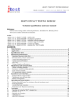
Fig. 4: A2320 Display Enhacer Board
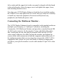
Fig. 5: A2320 - Installation, Right side View
When the A2320 is in place, secure it with the screws that held the cover plate in
place by first inserting the lower screw through the rear panel and screwing it
loosely into the thread on the metal bracket attached to the board. You may have to
loosen the two mounting bracket screws that hold the metal bracket to the A2320
circuit board in order to obtain the proper fit. Gently tilt the board
7
left or right until the upper hole in the rear panel is aligned with the thread
in the metal bracket. Insert the upper screw and tighten the upper, lower,
and mounting-bracket screws.
Now that your A2320 Display Enhancer board has been installed, replace
the A2000's cover and replace the five screws that you removed. Carefully
re-install any removed equipment, the mouse and keyboard, any
peripherals, and finally the power cord.
Connecting the Multiscan Monitor The A2320 Display Enhancer board is compatible with standard multiscan
(multiple sync-frequency or "multisync") monitors, including the
Commodore 1950 Multiscan Monitor, and provides a standard female DB
15 VGA-style connector for the monitor. Using a shielded cable with a
DB 15 male plug on one end, plug the monitor cable into the A2320's
video output connector, the other end into the monitor, and tighten the
screws on the cable connectors at both the computer and monitor ends. If
the multiscan monitor that you are using does not provide a DB 15 VGAcompatible cable, please see your local dealer to obtain an adapter that
will allow your specific monitor to work with standard 15-pin VGA video
boards.
8
3.
Adjusting the A2320's
Fine Tuning Control
The A2320 Display Enhancer has been factory-adjusted to work with both NTSC
and PAL-based Amiga A2000s (Note: NTSC is the video standard that is used
throughout most of North America, Latin America and Japan. PAL is the video
standard that is used throughout most of Europe). Therefore, the only adjustment
that is usually necessary for a newly-installed A2320 is done with the Fine Tuning
control screw ("PHASE ADJUST"). When you install the A2320 into any A2000
you may have to adjust this fine tuning control. There are actually two tuning
adjustment controls, Fine and Coarse. If for some reason the Fine tuning adjustment
fails to properly provide a stable video display, please see the 'Troubleshooting'
chapter later in this manual.
Adjustment Procedure To adjust the A2320's tuning controls, you must have already installed the A2320
board as described in the previous chapter and connected the multiscan monitor to
the A2320's video output. Insert the A2320 Test/Demo disk, included in the
shipping carton, into floppy drive DF0: and power on the monitor and then the
Amiga. From the front of the machine reach around to the back of the Amiga and
enable the de-interlacing/scan-doubling circuitry of the A2320 by flipping the
toggle switch leftward to the "Active Mode" position. The display may look unusual
and may have pixels "jittering," but it should be otherwise recognizable. Don't
worry - the fine tuning adjustment will stabilize the display. If the Amiga does not
boot up normally, please see the 'Troubleshooting' chapter.
After switching the A2320 into Active mode, locate the fine tuning control hole in
the metal bracket just above the mode switch (see Fig. 4). Position the monitor so
that while reaching around to the right rear of the Amiga with the plastic alignment
tool you will be able to see the screen. After allowing the A2320 board and the
Amiga to warm up for approximately five minutes, you are ready to begin the
adjustment. If you have an Amiga with the Enhanced Chip Set and AmigaDOS 2.0,
skip to the 'ECS and AmigaDOS 2.0' section further below.
9
Standard Chipset and AmigaDOS 1.3 or earlier First, double-click on the A2320 Test/Demo disk icon and then on the
'A2320_Test_1' icon. Now insert the alignment tool straight into the fine tuning
control hole and engage it in the screw slot, and slowly turn the fine tuning control
clockwise or counterclockwise until all parts of the display are stable and are not
jittering. This should occur in one to fifteen full turns of the fine tuning control
screw. If you think that you have gone too far, turn the fine tuning control in the
opposite direction. You may be able to hear a slight clicking sound as you turn the
fine tuning control. This just indicates that the screw has reached the end of its
travel, and you should turn the screw in the opposite direction.
When you have achieved the best image you can with the 'A2320_Test_1' pattern,
you should temporarily push its screen to the back so you can open the second test
screen. Click anywhere in the lower half of the image to bring up a title bar with
depth gadgets in the upper right corner of the screen. Click on the Back gadget to
bring up the Workbench screen and double-click on the 'A2320_Test_2' icon. Again
using the alignment tool, slowly turn the fine tuning control clockwise or
counterclockwise until all parts of the 'A2320_Test_2' display are stable and are not
jittering.
Click anywhere in the lower half of the image to produce the depth gadgets and
again click on the Back gadget, then the Workbench screen's Back gadget to reveal
the first pattern screen, and check to be sure that the 'A2320_Test_1' image is still
stable with your new fine tuning setting. Be sure to look closely at all the colors,
lines, and patterns for both images when adjusting the fine tuning control for a
sharp and stable display. When all test patterns appear satisfactory, adjustment is
complete, and you can click in the upper-left corner of each image to close the
screens and return to the Workbench screen.
ECS and AmigaDOS 2.0 If you have the ECS chip set and AmigaDOS 2.0, then you should perform the
following fine tuning adjustment procedure. Boot your machine with AmigaDOS
2.0 as you normally would from floppy or hard disk, depending on your system.
Open the Workbench™ 2.0 'Prefs' drawer, and double-click on the 'WBScreen'
icon. With the
10
mouse, select the 'Superhires' video mode and click on the 'Use' gadget.
Your Amiga will then switch to the 1280 X 200/256 display mode. You
should then flip the A2320 mode switch to the right (away from the fan) to
put the A2320 into Bypass mode. Double-click on the A2320 Test-Demo
disk icon and then on the 'A2320_Test_3' icon to bring up a special test
pattern window on the screen.
Now insert the alignment tool straight into the fine tuning control hole and
engage it in the screw slot, and slowly turn the fine tuning control
clockwise or counterclockwise until all parts of the display are stable and
are not jittering. This should occur in one to fifteen full turns of the fine
tuning control screw. If you think that you have gone too far, turn the fine
tuning control in the opposite direction. You may be able to hear a slight
clicking sound as you turn the fine tuning control. This just indicates that
the screw has reached the end of its travel, and you should turn the screw
in the opposite direction.
When you have achieved the best image you can with the 'A2320_Test_3'
pattern, double-click on the 'A2320_Test_1' icon. Flip the mode switch to
Active mode and again using the alignment tool, slowly turn the fine
tuning control clockwise or counterclockwise until all parts of the
'A2320_Test_1' pattern are stable and are not jittering. Click anywhere in
the lower half of the image to bring up a title bar with the depth gadget in
the upper right corner of the screen. Click on the gadget to bring up the
Workbench screen, double-click on the 'A2320_Test_2' icon, and repeat
the same adjustment procedure as with 'A2320_Test_1'. When it too is
stable, use the depth gadget to return to the 'A2320_Test_1' pattern and
check to make sure that it has not lost stability with the new fine tuning
setting. Then return to Bypass mode and recheck the 'A2320_Test_3'
pattern as well. Be sure to look closely at all the colors, lines, and patterns
of all three images when adjusting the fine tuning control for a sharp and
stable display. Once all test patterns appear satisfactory, adjustment is
complete and you can return the mode switch to the Active position. Click
in the upper-left corner of each test pattern to close the screens and return
to the Workbench screen.
You may now click on the icons of any of the included graphic demos
supplied on the A2320 Test/Demo disk and see how much better the
Amiga video display appears. If you switch the mode switch on the back
of the A2320 board from Active mode to the
11
right (Bypass mode), you can observe the normal non-enhanced Amiga video
display for comparison - you'll never want to go back. Enjoy!
NOTE: If after attempting to adjust the fine tuning control you are unable to obtain
a stable display, please refer to the 'Troubleshooting' chapter of this manual. Once
you have the A2320 operating, you may need to adjust your monitor's position and
size controls to center the screen on your monitor. If, over time, the display
develops pixel jitter, you may have to slightly adjust the fine tuning control to make
the display stable again.
12
4.
Operation and
Compatibility
The A2320 Display Enhancer board is capable of operation in all the graphics
modes available on the Amiga. In the non-interlaced Amiga modes (i.e. 320 X
200/256 and 640 X 200/256) the A2320 Display Enhancer will automatically
operate in Scan-double mode. This means that the A2320 is repeating every line to
increase the raster scan rate from 15.734 KHz NTSC (15.625 KHz PAL) to 31.46
KHz NTSC (31.25 KHz PAL). In this mode of operation, the A2320 removes
visible scan lines with full overscan and HAM support, making text and graphics
solid and professional. Another benefit of this mode of operation is that there are no
motion artifacts (i.e. shearing or ghosting effects with moving objects) which has
obvious value for animation and game software which features rapid object
animation.
In the interlaced Amiga modes (i.e. 320 X 400/512 and 640 X 400/512) the A2320
Display Enhancer will automatically operate in De-interlace mode. Here, the A2320
is storing the previous video field and combining it with the current incoming video
field. This removes flicker and visible scan lines, still with full overscan and HAM
support, again by doubling the raster scan rate. In this mode of operation you may
notice some motion artifacts (i.e., ghosting effects) with fast-moving animated
objects.
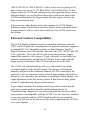
ECS Compatibility Another Amiga display mode, which uses the ECS (Enhanced Chip Set) supported
under AmigaDOS 2.0, is called 'Productivity' mode. This mode has a display of 640
X 480 with 4 colors out of a palette of 64, and a raster scan rate of 31.46 KHz. In
this display mode the A2320 Display Enhancer will automatically bypass the video
data to the multiscan monitor since the raster scan rate is already at 31.46 KHz and
has no flicker or visible scan lines.
Still another Amiga display mode which uses the ECS under Amiga-DOS 2.0 is
'Superhires' mode. This mode has a display of either
13
1280 X 200/256 or 1280 X 400/512, with 4 colors out of a palette of 64,
and a raster scan rate of 15.734 KHz NTSC (15.625 KHz PAL). In this
display mode the A2320 only samples every other pixel and may cause a
distorted display, so you should set the mode switch on the back of the
A2320 metal bracket to the Bypass mode (flip the toggle switch to the
right, away from the fan).
If there are any other display modes that confuse the A2320 Display
Enhancer, simply flip the mode switch to Bypass mode and whatever the
Amiga generates will be sent to the monitor as if the A2320 were not in
the system.
External Genlock Compatibility The A2320 Display Enhancer board is compatible with many external
NTSC and PAL genlocks, including the new genlock extensions supported
in AmigaDOS 2.0. Compatible genlocks include Mimetics' AmiGen,
Digital Creations' SuperGen and the Omicron Video 701 (NTSC) and 702
(PAL) genlocks. To use the A2320 with an external genlock, simply
connect the genlock to the Amiga's 23-pin video port, as detailed by the
genlock's manufacturer, and put the A2320 into Active mode (flip the
toggle switch on the back of the A2320 metal bracket to the left).
The A2320 will automatically provide you with a flicker-free highresolution display of the Amiga's output. The genlock will function
normally and provide the composite monitor or VCR connected to the
genlock's video out connector with overlaid Amiga graphics and video as
normal. If you experience any problems in obtaining a stable display, try a
slight adjustment of the fine tuning control. If this does not help, please
see the 'Troubleshooting' chapter in this manual.
If you cannot adjust the fine tuning control to produce a stable display
with your external genlock installed and the information in the
'Troubleshooting' chapter does not correct the problem, then most likely
your genlock is incompatible with the A2320. You can, however, continue
to use your genlock with the A2320 board installed as you normally
would; you will just not be able to use the video output from the A2320 to
view your displays.
14
Software Compatibility The A2320 Display Enhancer is compatible with, and transparent to,
Amiga software packages. The A2320 is also compatible with all Amiga
display modes, including hold-and-modify ("HAM") modes, Amiga
overscan modes, and the new ECS modes, and fully supports the Amiga's
4096-color palette.
Monitor Compatibility The A2320 Display Enhancer board's video output is compatible with
standard multiscan (multisync) monitors (not "VGA-ONLY" monitors)
and provides a standard DB15 VGA-style video output connector. A list of
multiscan monitors that are compatible includes: Commodore's 1950
Multiscan Stereo monitor, NEC MultiSync® and MultiSync® II,
Mitsubishi Diamond Scan™, Zenith ZCM 1490 (NTSC Amigas only),
Taxan Multivision™ 770 Plus, AOC Multisync CM-314, and others. You
may have to obtain an adapter cable from your local dealer that will allow
your specific multiscan monitor to work with the standard DB15 VGAstyle connector, or you may construct your own cable using the A2320
video pinouts as shown in Appendix B, matched to your specific monitor's
identical input signals as shown in the user's manual supplied with your
monitor.
Using the A2320 in NTSC and PAL Systems The A2320 Display Enhancer board has been factory-adjusted to work
with both NTSC and PAL Amiga systems and will automatically function
correctly in both environments, providing that you have followed the
adjustment procedure as described earlier. lf you experience any problems,
please see the following chapter, which will help you achieve the best
possible display.
15
5.
Troubleshooting
General Troubleshooting If your Amiga does not boot up normally with the A2320 Display Enhancer
installed, or if you are unable to produce a stable display, please do the
following:
1)
Make sure the monitor you are using is a multiscan VGA-compatible
monitor and that your monitor cable is correctly installed and has the
correct signal connections between your particular multiscan monitor
and the standard 15-pin VGA connector on the A2320. Also check to
be sure that your cables are screwed tightly into their connectors at
both ends and that your monitor is set for the correct operational mode
(i.e. analog RGB, etc.)
2)
Make sure that all external peripherals are properly connected to the
Amiga and that their cables are screwed tightly into their connectors.
3)
Make sure that the mode switch on the back of the A2320's metal
bracket is in the correct position for the fine tuning control adjustment.
The mode switch should be flipped to the left (toward the fan). This is
the Active mode.
4)
Recheck your fine tuning control adjustment as described in Chapter 3.
You may need to make sure that you have turned the fine tuning
control completely through its range of fifteen full turns and slowly
back again in order to correctly fine tune the A2320.
5)
If the previous checks have not isolated the problem then make certain
that the A2320 is installed correctly in the Amiga's video slot with the
mounting screws securely attached to the back cover of the machine.
You may need to remove the cover of the Amiga and re-install the
A2320 board in the video slot and ensure that no internal cables have
been dislodged and no other components or wires are contacting
17
the A2320 board itself. At this time, carefully make sure that the
IC chips are firmly seated in their sockets on the A2320 board
itself. Then re-install the A2320 board and confirm that it is
properly seated.
6)
If, after you have attempted to check for correct A2320 board
installation and fine tuning control adjustment, you are still having
problems, then your A2320 board may need to have its Coarse
tuning control adjusted. Please see the section on 'Coarse and Fine
Tuning Control Adjustment' later in this chapter. You may also
need to perform the check in step 7.
If you are having problems obtaining a stable display when you
have an external genlock connected to your Amiga, please try
readjusting the fine tuning control and see if that fixes the
problem. If the A2320 board was operating correctly before you
connected your genlock to the system and adjusting the fine tuning
control doesn't correct the problem, then turn off and unplug the
Amiga, and proceed with the following check.
7)
To insure that your computer was set properly at the factory,
remove the Amiga's cover, as shown in the chapter on installing
the A2320, and check to see that the shorting block on jumper
J300 on the motherboard is on the default setting. This jumper is
located under the power supply (noted in Fig. 2) but you may be
able to see the jumper by looking back from the right front corner
of the Amiga. The shorting block should be connecting the
leftmost and center pins of the 3-pin jumper. This jumper
determines the time base used for the 50/60 Hz CIA timer chip. In
normal (factory default) position, the 50/60 Hz TICK clock, based
on AC line frequency, is used as a time base. In the alternate
position, the vertical sync pulse from the video section is used.
The A2320 may not operate correctly if the vertical sync pulse is
used as the CIA time base, with the jumper in the right-hand
position.
18
Coarse and Fine Tuning Control Adjustment If fine tuning efforts have not succeeded in stabilizing the display then you
should perform the adjustment procedure described below.
WARNING!!!
The following procedure involves working within the case of the
Amiga with the cover removed and the unit POWERED ON. High
voltages are present inside the case. Severe injury to operator and
damage to equipment could result from carelessness or ignorance
in attempting to perform the adjustment.
Turn OFF the Amiga and the monitor and remove the cover of the A2000
as described in the Installation chapter. Reconnect the mouse, keyboard,
and multiscan monitor to the Amiga. Turn the machine so that the A2320
board can be seen in the A2000 video slot and locate the blue trimmer
capacitor VC101 on the upper right section of the A2320 circuit board (see
Fig. 4.) With the multiscan monitor still connected to the A2320 board and
the A2320 Test/Demo disk in DF0:, power on both the Amiga and the
monitor. (To minimize the likelihood of shock, be VERY careful not to
touch or let anything touch the power supply or any components in
the open Amiga case unless otherwise instructed.)
Below the trimmer capacitor VC101, locate the jumper block CN3. Move
the black shorting block from the 'CLOSELOOP' position to the
'OPENLOOP' position. Insert the plastic alignment tool into the
adjustment hole as before. Turn the fine tuning control clockwise twenty
full turns, then counterclockwise seven full turns. This centers the tuning
control adjustment to mid-range.
Now from the right side of the machine, turn the monitor so that the screen
can be seen, and put the A2320 into Active mode using the mode switch
(flip it to the left, toward the fan). Insert the plastic alignment tool into the
top of the blue trimmer capacitor VC101 (twirl it a bit to engage the
trimmer slot if necessary) and slowly turn the tool, observing the effects
on the monitor. (Don't be afraid of turning too far; the trimmer just "wraps
around" each full turn.)
19
Turn the trimmer slowly until the screen stabilizes, keeping in mind that this is a coarse adjustment. When the display
is as stable as possible, remove the alignment tool from the trimmer. Move the shorting block on the CN3 jumper back
to the 'CLOSELOOP' position and insert the plastic alignment tool into the fine tuning control hole in the metal
bracket.
Now return to Chapter 3 and repeat the fine tuning procedure described there.
Finally, turn OFF both the Amiga and the monitor and remove the power cord. Re-install the
A2000's cover and replace the five screws that were removed. Carefully re-install any removed equipment, peripherals,
and finally the power cord. This completes the alignment of the A2320 Display Enhancer board for your Amiga setup.
NOTE: If you are still unable to properly adjust the A2320 and obtain a stable display with your specific
Amiga/monitor setup, please contact your local Authorized Commodore service center.
20
Appendix A:
Theory of Operation
Background Information In the world of Amiga video there are two primary modes of operation, interlaced
and non-interlaced. The Amiga sends out video information in 'fields' of horizontal
scan lines to make up a display on the monitor. In the interlaced mode, there are two
fields, called even and odd, which when taken together make up a complete video
frame. These fields are displaced from each other on the screen so that their
respective scan lines are interleaved. In other words, the lines of the even field
alternate vertically with the lines of the odd field. From top to bottom on the screen
there is one line of the even field, then one line of the odd field, another line of the
even field, etc., hence the term "interlace."
The video frame rate is 30 frames per second, so each field (half a frame) takes
1/60th of a second to be drawn on the screen - the standard Amiga hardware is not
capable of sending out video data any faster than this. In the time that it takes for
the electron beam to draw the second of the current interlaced frame's two separate
fields, the first field has faded in brightness, since the glow of the phosphor dots the
beam scans starts to dim as soon as the beam passes to the next pixel. When the
refresh rate (how many times per second each field is redrawn) is too low - 30 Hz or
less - for the human eye to see as a single image, the perceived result is the
annoying flicker of interlace mode. Non-interlace screens are essentially the SAME
field scanned TWICE each frame, or sixty times per second, which is rapid enough
to avoid the flicker.
With that background information we can now explain how the A2320 Display
Enhancer board removes the flicker from the Amiga's interlaced display modes, and
visible scan lines in non-interlaced display modes.
The A2320 Display Enhancer board is capable of operation in all Amiga graphics
modes, to which it automatically adapts. In the non-interlaced graphics modes (i.e.
320 X 200/256 and 640 X 200/256) the A2320 Display Enhancer will automatically
operate in Scan-
21
double mode. This means that the A2320 is repeating every line, at twice standard
video rate, to increase the raster scan rate from 15.734 KHz NTSC (15.625 KHz
PAL) to 31.46 KHz NTSC (31.25 KHz PAL). In this mode of operation, the A2320
removes visible scan lines from all images, fully supporting overscan and HAM
displays, yielding a crisp and solid display. Another benefit of this mode of
operation is that there are no motion artifacts, (i.e. shearing or ghosting effects)
which has obvious value for animation and game software which has rapidlymoving objects.
In the interlaced Amiga modes (i.e. 320 X 400/512 and 640 X 400/ 512) the A2320
Display Enhancer automatically switches into De-interlace mode. This means that
the A2320 is storing the previous video field and combining it with the current
incoming video field at twice the video rate, to remove visible scanlines without
adding flicker, while fully supporting overscan and HAM display modes. In this
mode of operation you may notice some motion artifacts (i.e. a ghosting effect) with
rapidly animated objects.
The A2320 has also been designed to be compatible with the new graphics modes
available with the Enhanced Chip Set (ECS) under AmigaDOS 2.0.
The ECS 'Productivity Mode' has display of 640 X 480 pixels with 4 colors out of a
palette of 64. In this display mode the A2320 will automatically bypass the video
data to the multiscan monitor since the raster scan rate is already at 31.46 KHz and
has no flicker or visible scan lines.
The ECS 'Superhires Mode' has a display of either 1280 X 200/256 or 1280 X
400/512 pixels with 4 colors out of a palette of 64, and a raster scan rate of 15.734
KHz NTSC (15.625 KHz PAL). In this display mode the A2320 only samples every
other pixel and may cause a distorted display, so the board must be put into Bypass
mode by setting the mode switch to the right.
22
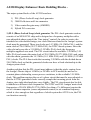
A2320 Display Enhancer Basic Building Blocks The major system blocks of the A2320 board are:
1)
2)
3)
4)
PLL (Phase Locked Loop) clock generator
384K Field store and Line memories
Video controller gate array (AMBER)
Hybrid D/A converter
1) PLL (Phase Locked Loop) clock generator The PLL clock generator section
consists of an NE564 PLL chip and is designed as a frequency multiplier with a
user-adjustable phase control (the "fine tuning" control). In order to create a deinterlaced or scan-doubled image, two clocks that are related to the Amiga's system
clock must be generated. These two clocks are 14.3 MHz (14.1 MHz PAL), and the
main clock of 28.63 MHz (28.375 MHz PAL) for NTSC-based systems. Since the
video slot only provides a 3.58 MHz (3.55 MHz PAL) clock, the frequency
multiplier approach was used. The PLL circuit takes the available 3.58 MHz (3.55
MHz PAL) and creates the main clock of 28.63 MHz (28.375 MHz PAL) and, using
a divider chain, generates the 14.3 MHz (14.1 MHz PAL) and 3.58 MHz (3.55 MHz
PAL) clocks. The PLL then tracks the incoming 3.58 MHz with the divided-down
28.63 MHz clock so that the generated clocks now have a fixed relationship to the
Amiga system clock.
Another problem that the PLL circuit must address is that the pixels coming from
the Amiga's Denise chip at 14 MHz (or 28 MHz in ECS modes) do not have a
constant phase relationship, across process variations, to the available 3.58 MHz
clock. This problem requires the use of a phase circuit that must be user-adjusted so
that the A2320's generated clocks correctly sample the incoming pixels from the
Amiga, since individual machines vary slightly. The PLL circuit must also be able
to handle two different clock frequencies. The NTSC and PAL Amigas' main clock
frequencies of 28.636 MHz/28.37516 MHz (less than a 1% difference) require the
use of a trimmer capacitor (coarse adjustment control) to set a median frequency
which is close enough so that regardless of which system the A2320 is in, the PLL
can function correctly.
23
2) 384K Field Store and Line memories
The A2320 uses three 1-MBit CMOS Frame memories to store a field of 12-bit-wide
pixels. The frame memories allow simultaneous read/write action in such a manner
that as one new 12-bit-wide pixel is being written, the previous field's 12-bit-wide
pixel, at the same line/field location, is being read. The AMBER gate array controls
the reading and writing of the frame memories so that this action happens properly.
The other major element of the A2320 memory section is the line memories. The
line memories are used to double the pixel rate of the incoming video data, as well as
for the field-delayed data from the frame memories. The output of each pair of line
memories (two for the current line data and two for the field-delayed data) is sent to
the gate array controller für multiplexing and reclocking of the video data.
3) Video controller gate array (AMBER)
The heart of the A2320 Display Enhancer system is the AMBER gate array chip.
This chip provides synchronization and control signals for the correct operation of
the frame memories and line memories, as well as the proper horizontal and vertical
sync signals that control the multiscan monitor. The AMBER chip also controls the
pixel data path so that the correct line (i.e. current or delayed) is sent to the D/A
converter, depending on the operational mode (i.e. De-interlace or Scan-double
mode). The AMBER chip must also detect whether the A2320 is operating in a PAL
or NTSC Amiga system and whether or not there is an extemal genlock in the
system, to adjust the A2320 control functions accordingly.
4) Hybrid D/A converter
The de-interlaced/scan-doubled 12-bit-wide digital RGB data coming from the
AMBER gate array must be converted to analog RGB for the multiscan monitor to
display the image. A custom hybrid digital-to-analog converter using a simple, lasertrimmed weighted resistor network is employed for this conversion process. This
D/A converter is capable of directly driving a 75-ohm load.
24
Appendix B:
Technical Specifications
1)
Horizontal Frequency:
NTSC-31.468 Khz unbypassed, 15.734 Khz bypassed
PAL-31.25 Khz unbypassed, 15.625 Khz bypassed
2)
Vertical Frequency:
NTSC-60 Hz
PAL-50 Hz
3)
Video Signal outputs: Analog, 0.7 Vp-p/75 ohm, positive polarity.
4)
Video Sync Signals: Separate, TTL level, negative polarity.
5)
Pixel output:
NTSC-35nS wide, 910 pixels/line output with 802 active
PAL-35nS wide, 908 pixels/line output with 802 active
6)
Horizontal Sync Pulse:
NTSC-2.4µS wide, active low, TTL level
PAL-2.4µS wide, active low, TTL level
7)
Vertical Sync Pulse:
NTSC-190µS wide, active low, TTL level
PAL-160µS wide, active low, TTL level
8)
Overscan support:
NTSC-768 X 489 worst case
PAL-768 X 576 worst case
Note: Certain software packages may use overscan this severe, however
the operating system nominally does not perform to this level.
9)
Connector: DB15 female VGA-style connector and pinout.
10) Monitors supported: Most multiscan VGA monitors such as
Commodore 1950, NEC MultiSync® and MultiSync® II, Mitsubishi
Diamond Scan™, Zenith ZCM 1490 (NTSC Amigas only), Taxan
Multivision™ 770 Plus, AOC Multisync CM-314, and others.
25
11)
FCC Approval: FCC Class B approved.
12)
Power Consumption: +5VDC ±5%, 3 Watts.
13)
Video Bandwidth: 30 MHz @ -3dB.
A2320 DB15 Video pinout:
Output Connector: DB 15 female VGA-style connector.
Pin 1: Analog Red
Pin 2: Analog Green
Pin 3: Analog Blue
Pin 4-8: Ground
Pin 9: No Connect
Pin 10-12: Ground
Pin 13: N-Hsync
Pin 14: N-Vsync
Pin 15: No Connect
26
363320-01
Printed in Hong Kong
Commodore Business Machines, Inc.
1200 Wilson Drive • West Chester, PA 19380
6/90
Amiga Hardware World
Everything about Amiga hardware...
~
http://amiga.resource.cx