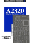
1
UC-1000 Universal Laser Controller Operation Manual 6500 Harbour Heights Parkway Mukilteo, WA 98275 USA 1-800-SYNRAD1 Tel: (425) 349-3500 Fax: (425) 485-4882 Web Site: http://www.synrad.com E-mail: [email protected] Revised April 1998 Contents Safety Precautions 1 Introduction 2 Function and Application 2 UC-1000 Models 2 Getting Started Connecting the UC-1000 3 3 4 Operating Modes 5 Start Up Operation 6 Front Panel Controls / Indicators 6 Rear Panel Connectors 7 Control Signals 8 Gate Function and Setup 11 Clock Frequency Setup 14 Troubleshooting 16 Technical Reference 18 UC-1000 Specifications 18 UC-1000 Operating Modes 18 Appendix A 48-CL Closed Loop Stabilization Kit A-1 Contents UC-1000 Operation Manual Safety Precautions Please read these instructions carefully before using your laser. To prevent injury to personnel or damage to your laser, follow all safety precautions, handling and setup instructions as described here and in the laser operation and service manual. Safe operating practices should be exercised at all times when actively lasing. To prevent exposure to direct or scattered laser radiation, follow all safety precautions as specified here or in the laser operation and service manual. Improper handling or operation may result in exposure to hazardous invisible laser radiation, damage to, or malfunction of the laser. Severe burns will result from exposure to the laser beam. Always wear safety glasses with side shields to reduce the risk of damage to the eyes when operating the laser. 1 Safety Precautions UC-1000 Operation Manual Introduction Function and Application The UC-1000 is a stand-alone controller designed to interface between your application and SYNRADs 48, 57, 60 and Evolution Series CO2 lasers. It provides for manual, remote, or closed loop power control of your laser. UC-1000 Models The UC-1000 controller is available in two basic configurations: UC-1000 The UC-1000 is SYNRADs standard laser controller. Use this version if your application does not require the use of an external gating signal to switch the laser on and off. UC-1000X The UC-1000X (Mod-X) controller is identical to the standard unit with the exception that it requires a logic high signal at the Gate input connector to enable laser output. Use this version if you are applying an external gating signal to control the laser. The only difference between standard and Mod-X controllers is the functioning of the gate input. On the standard UC-1000, the gate input is set to internal pull-up (normally on) mode. A logic high input signal or an open (or disconnected) Gate input connector will cause the laser to turn on. To gate the laser off, a logic low input or short circuit must be applied to the Gate input connector. Mod-X controllers have the gate input set to internal pull-down (normally off) mode. This prevents the laser from being enabled unless a logic high (+3.5 V to 5 VDC) signal is applied to the Gate input connector. The pull-down (normally off) mode ensures the laser is always off in the event the Gate signal is open or disconnected, short circuited to ground, or an asserted logic low or tri-state (electrically floating) condition exists. If your application changes, you can reconfigure from one version to the other simply by changing a switch setting inside the controller. See page 11, Gate Function and Setup, for a detailed explanation of gate function logic and switch setup. Introduction: Function and Application UC-1000 Operation Manual 2 Getting Started Connecting the UC-1000 Power Connection All UC-1000 models are shipped with a 115 VAC wall plug transformer / rectifier delivering 24 VDC. For line voltages other than 115 VAC, compatible transformers can be purchased locally. If using the wall plug power supply, insert its female barrel plug into the UC-1000s Pwr 24 VDC input jack to provide power to the unit. Refer to page 7, Figure 2. On Series 48 lasers, version G or newer, you can power the UC-1000 by connecting the supplied power cable between the Pwr 24 VDC input jack and the lasers side-mounted UC-1000 power connection. Power to the UC-1000 can also be provided from any 2432 VDC source capable of supplying 200 milliamperes (mA) of current. If you intend to supply power from an alternate supply ensure the connector polarity is correct: tip polarity is positive (+), ring polarity is negative (). Control Connection Series 48-1, 48-2 Lasers 1. 2. Attach one end of the supplied control cable to the UC-1000s rear panel Output BNC connector. Refer to page 7, Figure 2. Attach the other end of the control cable to the CTRL connector mounted on the rear of the laser. Series 48-5 Lasers 1. 2. Attach the long leg of the supplied Y control cable to the UC-1000s rear panel Output BNC connector. Refer to page 7, Figure 2. Attach the short legs of the Y connector to the CTRL 1 and CTRL 2 connectors located on the rear of the laser. Series 57-1/60-1 and Evolution 100/125 Lasers 1. 2. 3 Attach one end of the supplied control cable to the UC-1000s rear panel Output BNC connector. Refer to page 7, Figure 2. Attach the other end of the control cable to the CTRL IN connector (CONTROL IN connector on Evolution Series) located on the front or rear panel of the RF Power Supply. Getting Started: Connecting the UC-1000 UC-1000 Operation Manual Series 57-2/60-2 and Evolution 200/240 Lasers 1. 2. 3. 4. 5. Attach the supplied BNC Tee connector to the CTRL IN connector (CONTROL IN connector on Evolution Series) on the front or rear panel of the first RF Power Supply. Attach one end of the supplied control cable to the UC-1000s rear panel Output BNC connector. Refer to page 7, Figure 2. Attach the other end of the control cable to the BNC Tee connector on the first RF Power Supply. Attach one end of the second control cable to the CTRL IN connector (CONTROL IN connector on Evolution Series) on the front or rear panel of the second RF Power Supply. Attach the other end of the second control cable to the BNC Tee connector mounted on the first RF Power Supply unit. New cables up to 25 feet long can be user-fabricated, but must be shielded. We recommend using RG-174 miniature coaxial cable. In addition to the Output BNC connection, the UC-1000 also provides a subminiature phone Output jack for use with older laser models. Start Up Ensure that UC-1000 Mode switch settings and any external control connections have been properly made. Turn on the UC-1000 by putting the front panel Power switch in the On position. The UC-1000s red Power On Indicator will illuminate indicating that power is applied to the controller. Controller output is suppressed for a period of 150500 milliseconds (ms) after power-up. Operating Modes Six operating modes are supported by the UC-1000. These modes include Standby, Manual, remote, and closed loop laser power control. In all modes a tickle signal is applied to the laser to ionize the gas without causing laser emission. By maintaining a pre-ionized state, the laser responds predictably and almost instantaneously to command signals even when there has been considerable laser off time between pulses. See page 18, Technical Reference, for operating mode specifications. Standby (STBY) This mode is used when initially starting, or to temporarily pause, laser operation. Only the 1 microsecond (µs) output tickle pulse is generated. Manual (MAN) In this mode, laser power can be varied manually by means of the Power Adj knob on the front panel. This allows you to manually vary the lasers output power from zero to maximum by varying the UC-1000s PWM duty cycle output from tickle to 95%. An external gating signal is the only active input in this mode. Getting Started: Connecting the UC-1000 UC-1000 Operation Manual 4 Remote Voltage Control (ANV) In this mode, an analog 010 VDC signal applied to the ANV/C input connector remotely controls laser power. PWM duty cycle output is approximately proportional to voltage applied. The front panel Power Adj knob is disabled when the Mode switch is set to ANV. Remote Current Control (ANC) In this mode, an analog current applied to the ANV/C input connector remotely controls laser power. Power output is zero at 4 mA and reaches maximum at 20 mA. PWM duty cycle output is approximately proportional to current applied. The 420 mA current loop is the standard industrial control interface for loop supervision. The front panel Power Adj knob is disabled when the Mode switch is set to ANC. Closed Loop Operation (CLL, CLH) Closed Loop Low gain or Closed Loop High gain operation is available with Series 48-1 or 48-2 lasers only. To provide closed loop power regulation a SYNRAD 48-CL Closed Loop Stabilization Kit is required and must be factory installed. In Closed Loop mode, the UC-1000 Power Adj knob sets the control (regulation) point while the sensor feedback loop regulates the selected power level to within ±2% stability. A gating signal can still be used to control laser on/off time. See page A-1, Appendix A, for further information. Note: The ANV/C input is disabled when the UC-1000 is operated in either Closed Loop mode. 5 Getting Started: Operating Modes UC-1000 Operation Manual Operation Front Panel Controls and Indicators UC-1000 front panel controls and indicators are described in this section. Each callout item in Figure 1 below refers to a numbered description in the accompanying text. 1 2 3 CLH ANC ANV CLL ON MAN 4 50% (MAN) POWER ADJ ON POWER STBY MIN MAX OFF UC-1000 Figure 1 Front Panel Controls / Indicators 1 Power Switch used to turn DC power to the UC-1000 controller circuitry on or off. 2 Power On Indicator illuminates to indicate that power is applied to UC-1000 controller circuitry when the Power switch is On. 3 Mode Switch allows you to select one of six modes of operation. Choices include Standby, two closed loop modes (low or high gain), two remote modes (analog current or voltage), and Manual. See page 5, Operating Modes, for detailed descriptions. 4 Power Adjustment Knob allows you to manually vary the PWM duty cycle from tickle to 95%, corresponding to a laser output power level from zero to maximum. Note: The manual Power Adj control is disabled when either remote voltage control (ANV) or remote current control (ANC) is selected. Operation: Front Panel Controls / Indicators UC-1000 Operation Manual 6 Rear Panel Connectors UC-1000 rear panel input and output connectors are described in this section. Each callout item in Figure 2 below refers to a numbered description in the accompanying text. 1 2 3 4 CL ADAPTOR PWR 24 VDC Figure 2 7 6 5 MADE IN USA ANV/C CL T.P. OUTPUT GATE Rear Panel Connectors 1 Pwr 24 VDC Input power (2432 VDC @ 200 mA) is connected to this jack. 2 CL Adaptor Mini-DIN input connection for the laser-mounted power sensor assembly when operation in the Closed Loop mode is desired. Closed loop operation provides power stability within ±2%. 3 CL T.P. BNC output test point connection to monitor the closed loop power sensor feedback voltage. 4 ANV/C Analog voltage or analog current BNC input connection for remote voltage (010 VDC) or remote current (420 mA) control using standard industrial control interfaces. 5 Output BNC output connector for connecting the control cable to the laser. A subminiature phono jack is also available for connecting the UC-1000 to older model lasers. 6 Gate BNC or subminiature phono input connectors available for an externally applied pulse train input. A gating signal allows you to rapidly control on/off switching of the laser at rates up to several kilohertz (kHz). The gating signal, when used, is generated by the equipment controlling your application such as a computer or programmable logic controller (PLC). Operation: Rear Panel Connectors UC-1000 Operation Manual Control Signals Pulse Width Modulation (PWM) The UC-1000 controls laser power by Pulse Width Modulation (PWM). At the standard 5 kHz frequency, a pulse varying in width between 0 µs, corresponding to zero power level, and 190 µs, maximum power level, controls laser output power. The front panel Power Adj knob or an ANV/C input sets PWM percentage or duty cycle. Your choice of control frequency depends on your application, in most cases the standard 5 kHz control frequency is appropriate. Output Signal The Output signal from the UC-1000 controls the lasers RF Driver(s), which regulate laser output power. By controlling the PWM Output signal, you can direct the laser to perform a variety of marking or cutting operations. PWM duty cycle controls the lasers power level. The standard PWM frequency is 5 kHz, which has a period of 200 µs. The duty cycle of a PWM waveform is the percentage of the period that the output signal is high. If the amplitude of the 5 kHz signal is high for 100 µs and low for 100 µs, it has a 50% duty cycle. If the signals amplitude is high for 190 µs and low for 10 µs it has a 95% duty cycle (maximum output power). Refer to Figure 3 below. In Manual and Closed Loop modes, PWM output is controlled using the UC-1000 front panel Power Adj knob. In ANV or ANC modes, a remote analog signal controls PWM duty cycle. 200µS 200µS 190µS 100µS 5kHz Control Signal with 50% Duty Cycle Figure 3 5kHz Control Signal with 95% Duty Cycle PWM Output Signal Note: The UC-1000 can be modified to achieve 100% duty cycle operation if required by your application. In general, increasing PWM above 95% provides little or no increase in laser output power. Consult SYNRAD for details and requirements. Although the operating standard frequency is 5 kHz, frequencies of 3 and 7.5 kHz are also available within the UC-1000 and can be set by the user. Consult SYNRAD for further technical information before changing frequencies since inadvertent laser operation may result. Operation: Control Signals UC-1000 Operation Manual 8 Tickle Pulse SYNRAD lasers require a tickle pulse, a 5 kHz PWM signal with a 1 µs pulse width, normally delivered by the UC-1000. The internally generated tickle signal is sent to the Output connector whenever power is applied to the UC-1000. The tickle pulse pre-ionizes the gas into a plasma state so that it is just below the lase threshold. Increasing pulse width beyond 1 µs will add enough energy to the plasma to cause laser emission. By applying a tickle pulse, the laser will respond predictably to your control signal even when there is considerable off time between applied pulses. For tickle pulse parameters, refer to Figure 4 below. 200µS 1µS 5 VDC 0 VDC Figure 4 Tickle Pulse Signal If an on/off control signal is sent to a laser without tickle, response time from the leading edge of the signal pulse until laser emission varies. This delay occurs because of the unpredictable amount of time required in creating a plasma state in the tube from a cold start. Plasma breakdown depends heavily on the amount of time that the laser has been off (without a control signal) before the next electronic on pulse is applied. This inconsistent response time can cause problems in precision applications where random delays in firing are unacceptable. The tickle pulse maintains the laser in a ready state for consistent and rapid response to PWM commands. Gate Signal An external gating signal applied to the Gate input connector may be used to command the UC-1000 to cycle the laser on and off. The gating signal, when used, is generated by the equipment controlling your application. Typically a computer or PLC would send signals through a digital I/O card to the UC-1000s Gate input connector. Gate control is useful for turning the laser off while steering mirrors or the workpiece are being repositioned for the next operation. The gating amplitude can be either of two states. A logic low state of 0 V to +0.5 VDC commands the laser off. A logic high state of +3.5 V to 5 VDC commands the laser on. Internal UC-1000 circuitry logically ANDs the Gate signal with the PWM signal. While the Gate signal is high, the PWM pulses are sent to the Output connector. The PWM signal controls laser power output and the Gate signal provides laser on/off timing control. 9 Operation: Control Signals UC-1000 Operation Manual Low Frequency Pulsing In applications where a Gate signal is used at frequencies below 500 Hz, the standard UC1000 controller allows the laser to produce a naturally-occurring spike or overshoot of laser power on the leading edge of each gating pulse. Consult SYNRAD if this is unacceptable for your application. External PWM Control The UC-1000 offers external PWM control utilizing standard industrial control loop supervision interfaces. A computer or PLC can generate 010 VDC voltage or 420 mA current signals providing remote PWM control of the UC-1000 via the ANV/C input connector. The UC-1000s front panel Power Adj knob is disabled when the Mode switch is set to ANV or ANC. In remote voltage mode, ANV, a digital-to-analog converter (D/A or DAC) card capable of generating 0 V to 10 VDC is required. In remote current mode, ANC, the D/A card must be capable of generating 4 mA to 20 mA. It is also possible to drive the ANV/C input from purely analog sources such as a remote potentiometer or an adjustable power supply. Specialized control software will be required for the majority of applications utilizing ANV/ANC remote control. Function Generators An external function generator may be used in place of the UC-1000 controller to generate the required pulses. Please consult SYNRAD for additional technical information regarding the requirements associated with using function generators in conjunction with SYNRAD lasers. Operation: Control Signals UC-1000 Operation Manual 10 Gate Function and Setup The Gate function can be used in all five active modes to gate, or switch, the laser. Connecting an external pulse train to the Gate input connector causes the UC-1000 to rapidly turn the laser on and off (laser enabled when input is logic high). The on laser power level is set by the UC-1000s front panel controls or remote inputs. During the off power level, a tickle signal is provided to the laser, maintaining plasma ionization. UC-1000 controllers manufactured after March 1998 are equipped with an internal switch (S1) on the Upgrade Module circuit board that allows you to select either a normally on or normally off mode for the gate input logic. Note: If Gate function logic is changed, ensure that the appropriate Warning or Notice sticker is applied to the UC-1000. See Figure 5 below. WARNING GATE INPUT IS SET FOR INTERNAL PULL-UP (NORMALLY ON) MODE. BEAM IS ON WHEN DISCONNECTED. SEE MANUAL FOR OTHER OPTIONS. NOTICE GATE INPUT IS SET FOR INTERNAL PULL-DOWN (NORMALLY OFF) MODE. BEAM IS OFF UNLESS +5V APPLIED. SEE MANUAL FOR OTHER OPTIONS. Figure 5 Gate Function Warning / Notice Stickers Users not planning to use a Gate signal should use the standard controller model or set switch S1 to select the internal pull-up (normally on) gate input mode. The UC-1000 will then operate without a +5 VDC signal being applied to the Gate input connector. Users intending to utilize an input Gate signal should use the Mod-X version controller or set switch S1 to select the internal pulldown (normally off) gate input mode. This ensures the laser is always off in the event the Gate signal is open or disconnected, short circuited to ground, or an asserted logic low or tri-state (electrically floating) condition exists. 11 Operation: Gate Function and Setup UC-1000 Operation Manual To change Gate function logic: 1. Disconnect power from the UC-1000 and remove all external connections. 2. Use a # 1 Phillips head screwdriver to remove the 2 screws located under the case and pull off the top cover. 3. Refer to Figure 6 below and locate super-miniature switch S1 on the upper left-hand corner of the UC-1000 Upgrade Module installed in sockets U2, U3, and U4. If your application requires a Gate signal proceed to Step 4. Go to Step 5 if your application does not require a Gate signal. DN UP Switch S1 shown in the pull-up or normally on position (fully clockwise). Gate input not being used. S1 DN S1 UP Switch S1 shown in the pulldown or normally off position (fully counterclockwise). Gate input in use. Caution: Do Not Adjust Trimpots. Adjustment May Cause Inadvertent Laser Output. Figure 6 4. Detail of Switch S1 For applications requiring a Gate signal, select the pull-down (normally off) gate input mode. The laser is enabled only when a logic high (+3.55 VDC) signal is applied to the Gate input connector. Rotate S1 counterclockwise using a jewelers screwdriver or small tuning wand. Since S1 does not click into position, be sure it is fully rotated in the counterclockwise direction without using excessive torque. Proceed to Step 6. Operation: Gate Function and Setup UC-1000 Operation Manual 12 13 5. If your application does not require a signal at the Gate input connector, select the pull-up (normally on) Gate input mode. The laser is enabled without a gating signal present. Rotate S1 clockwise using a jewelers screwdriver or small tuning wand. Since S1 does not click into position, be sure it is fully rotated in the clockwise direction without using excessive torque. 6. Replace and secure the UC-1000 top cover then reconnect all external connections. 7. Apply power to the unit and verify proper operation. Operation: Gate Function and Setup UC-1000 Operation Manual Clock Frequency Setup A 5 kHz frequency is used in most applications, however the standard 5 kHz clock rate can be changed to 3 kHz or 7.5 kHz. The unit is factory pre-set for 5 kHz. To change the nominal clock frequency: 1. Consult SYNRAD for technical information and requirements before changing clock frequencies to prevent inadvertent laser emission. 2. Disconnect power from the UC-1000 and remove all external connections. 3. Use a # 1 Phillips head screwdriver to remove the 2 screws located under the case and pull off the top cover. 4. Refer to Figure 7 below and locate the two miniature DIP switches on the circuit board. ON 1 2 Note: DIP Switches are shown in the standard 5 kHz setting. ON 1 2 Caution: Do Not Adjust Trimpots. Adjustment May Cause Inadvertent Laser Output. Figure 7 Detail of DIP Switches Operation: Clock Frequency Setup UC-1000 Operation Manual 14 5. Refer to Table 1 below. For 3 kHz operation: set switch 1 on both DIP switches to the on position. Set switch 2 on both DIP switches to the off position. For 7.5 kHz operation: set switch 1 and switch 2 on both DIP switches to the on position. For standard 5 kHz operation: set switch 1 on both DIP switches to the off position. Set switch 2 on both DIP switches to the on position. 6. Replace and secure the UC-1000 top cover then reconnect all external connections. 7. Apply power to the unit and verify proper operation. WARNING Consult SYNRAD for Further Technical Information Before Changing Frequencies. Inadvertent Laser Operation May Result. Clock Frequency DIP Switch Settings Upper DIP Switch SW2 SW1 Table 1 15 Lower DIP Switch SW1 SW2 3 kHz ON OFF ON OFF 5 kHz OFF ON OFF ON 7.5 kHz ON ON ON ON DIP Switch Settings Operation: Clock Frequency Setup UC-1000 Operation Manual Troubleshooting Perform the following steps to verify proper operation of the UC-1000 controller if you are experiencing trouble. Check Input Power 1. Ensure the front panel Power toggle switch is set to On. The UC-1000s red LED power On indicator should be lit when the Power switch is On. 2. Ensure the female power plug is firmly connected to the UC-1000s Pwr 24 VDC jack. 3. Unplug the female power plug and use a DC voltmeter to measure voltage at the plug tip. You should read a voltage in the range of 2432 VDC between the inner tip of the plug and its outer ring. Check Cable Connections 1. Verify that any UC-1000 input and output signal cables are properly connected for your application and those external signal sources are functioning properly. Check The UC-1000 Mode Switch Setting 1. Verify the UC-1000s Mode switch is set properly for your current application. Verify The UC-1000s Output Signal Note: The following troubleshooting steps assume gate input logic is set to the internal pull-up (normally on) mode. If your UC-1000 is set to the internal pull-down (normally off) mode, Mod-X version, you will need to apply a logic high (+3.55 VDC) signal to the Gate input connector in order for the UC-1000 to pass a PWM signal to the Output connector. 1. Disconnect all external signal cables. See note above. 2. If an oscilloscope is available, switch the UC-1000 to the Standby (STBY) mode and connect the oscilloscope to the Output connector. The UC-1000 should be generating a 1 µs wide tickle pulse at approximately 5 kHz with an amplitude of approximately 4.8 volts. 3. Set the UC-1000 to the Manual (MAN) mode and the Power Adj knob to minimum. Connect an oscilloscope, or a DC voltmeter (analog or digital), to the Output connector. At minimum power the oscilloscope should show the 1 µs tickle pulse. A DC voltmeter should read approximately 0 volts. Slowly increase the Power Adj knob to maximum power. The oscilloscope should display a signal (approximately 4.8 volt amplitude) increasing from a 1 µs wide tickle pulse to a 95% duty cycle square wave. A DC voltmeter should display a voltage rising linearly Troubleshooting UC-1000 Operation Manual 16 from 0 V to approximately 4.8 VDC as the Power Adj knob is increased from minimum to maximum power. Refer to page 8, Figure 3, for an illustration of UC1000 PWM output signals on an oscilloscope. If Your Application Uses A Remote Voltage (ANV) Signal Verify the UC-1000s Output signal. Note: The following troubleshooting steps assume gate input logic is set to the internal pull-up (normally on) mode. If your UC-1000 is set to the internal pull-down (normally off) mode, Mod-X version, you will need to apply a logic high (+3.55 VDC) signal to the Gate input connector in order for the UC-1000 to pass a PWM signal to the Output connector. 1. Switch the UC-1000 to the ANV mode and connect your control voltage signal to the rear ANV/C input connector. Connect an oscilloscope, or a DC voltmeter (analog or digital), to the Output connector. Set your ANV controller to generate a signal ramping from 010 VDC at a low frequency. The UC-1000s Output signal displayed on the oscilloscope should increase from a 1 µs wide tickle pulse to a 95% duty cycle square wave. A DC voltmeter should display an output voltage rising linearly from 0 V to approximately 4.8 VDC as the ANV input signal increases from 0 to 10 volts. If Your Application Uses A Remote Current (ANC) Signal Verify the UC-1000s Output signal Note: The following troubleshooting steps assume gate input logic is set to the internal pull-up (normally on) mode. If your UC-1000 is set to the internal pull-down (normally off) mode, Mod-X version, you will need to apply a logic high (+3.55 VDC) signal to the Gate input connector in order for the UC-1000 to pass a PWM signal to the Output connector. 1. Switch the UC-1000 to the ANC mode and connect your control current signal to the rear ANV/C input connector. Connect an oscilloscope, or a DC voltmeter (analog or digital), to the Output connector. Set your ANC controller to generate a signal ramping from 420 mA at a low frequency. The UC-1000s Output signal displayed on the oscilloscope should increase from a 1 µs wide tickle pulse to a 95% duty cycle square wave. A DC voltmeter should display an output voltage rising linearly from 0 V to approximately 4.8 VDC as the ANC input signal increases from 4 to 20 milliamperes. NOTICE Attempting repair of a UC-1000 Universal Laser Controller without the express authorization of SYNRAD, Inc. will void the product warranty. If troubleshooting or service assistance is required, please contact the SYNRAD Service Department. The UC-1000 electrical schematic included in this manual is provided solely for use as a reference when discussing technical issues with our Service Department. 17 Troubleshooting UC-1000 Operation Manual Technical Reference UC-1000 Specifications Power Input PWM Output Gate Input Gate Input Mode Clock Frequency 2432 VDC, 200 mA maximum from wall plug power supply or Series 48 (G version or newer) laser 05 VDC, 100 mA, 50 ohm, CMOS Driver TTL, 0 V to +0.5 VDC logic low (laser off), +3.5 V to 5 VDC logic high (laser on) User selectable by setting switch S1 on the Upgrade Module PCB. See page 11, Gate Function and Setup, for instructions on selecting normally on or normally off modes. Accurate to ±10%. User selectable via DIP switches on PCB. Nominal clock rate for standard operation is 5 kHz. See page 14, Clock Frequency Setup, for detailed instructions on selecting 3 kHz and 7.5 kHz frequencies. UC-1000 Operating Modes ANC Remote Analog Current 420 mA current, ±5% Zero power output @ 4 mA, maximum power output @ 20 mA Maximum safe input current: +100 mA Input resistance: 220 ohms to ground ANV Remote Analog Voltage 010 VDC, ±5% Zero power output @ 0 V, maximum power output @ 10 VDC Maximum safe input voltage: +15 VDC Input resistance: 10 k ohms to ground CLL Closed Loop Low Gain Sensor input: 313 VDC CLH Closed Loop High Gain Sensor input: 1.54 VDC Manual Mode MAN Gate input enabled only. Laser power control is accomplished using the Power Adj control knob. Output signal: tickle (zero power) to 95% duty cycle (maximum power) Standby Mode STBY Output signal: tickle signal only, 1 µs pulse @ the PWM clock frequency Remote Modes Closed Loop Modes Technical Reference: UC-1000 Specifications UC-1000 Operation Manual 18 Appendix A 48-CL Closed Loop Stabilization Kit Introduction The 48-CL Closed Loop Stabilization Kit is available for Series 48-1 and 48-2 lasers only and must be factory installed by SYNRAD. The 48-CL kit provides an effective, reliable method of stabilizing laser power output by optically sampling the beam and providing feedback to adjust the PWM duty cycle of the UC-1000s Output control signal. On Series 48 lasers, the beam passes through an optical sampler (replacing the standard front plate) before it exits the housing. Optical beam transmission is 92% since the sampler diverts approximately 8% of the output beam to a diffuser and thermopile detector. The thermopile detector signal is amplified to a signal level of 112 VDC and sent to the UC-1000 where a 5 kHz variable duty cycle signal is generated to maintain constant average laser output power. Safety Precautions Please read these instructions carefully before using your laser with a Closed Loop Stabilization Kit. To prevent injury to personnel or damage to your laser or CL Kit, follow all safety precautions, handling and setup instructions as described here and in the laser operation and service manual. Safe operating practices should be exercised at all times when actively lasing. To prevent exposure to direct or scattered laser radiation, follow all safety precautions as specified here or in the laser operation and service manual. Improper handling or operation may result in exposure to hazardous invisible laser radiation, damage to, or malfunction of the laser. Severe burns will result from exposure to the laser beam. Always wear safety glasses with side shields to reduce the risk of damage to the eyes when operating the laser. Getting Started Connecting the CL Kit Refer to page A-2, Figure 8 for a typical laser / 48-CL system setup diagram. A-1 1. Disconnect power from your laser and the UC-1000 controller. 2. Connect the CL interconnect cable between the laser-mounted 48-CL assembly and the UC-1000 CL Adaptor mini-DIN input connectors. 3. Set the UC-1000 Mode switch to the appropriate Closed Loop mode (CLL or CLH). Refer to page A-2, Closed Loop Mode Selection, for more information. Appendix A: Introduction 48-CL Closed Loop Stabilization Kit 4. Apply power and verify proper system operation. 48CL Model 48-1, 48-2 Laser 30 VDC Laser Power Supply Beam Blocker Beam UC-1000 CL Adaptor Output Gate NOTE: Set UC-1000 to Closed Loop Mode CLL or CLH TTL Source Figure 8 Typical Series 48 / 48-CL Setup Closed Loop Operation In CLL or CLH mode, the UC-1000 Power Adj knob should be set to provide laser power output in a range between 1085% of full power. The window on either side of that range allows the controller to maintain full dynamic range and regulation. Note that in both Closed Loop modes the 50% power mark on the Power Adj knob is no longer accurate since laser output becomes a linear function of the knob setting. Note: Remote PWM control through the ANV/C input is disabled when the UC-1000 is operated in either Closed Loop mode. Within the dynamic response time of the system, the UC-1000 controller can be gated from an external, low frequency signal source through the Gate input connector. Servo settling time to 90% of final value is approximately 2 ms. Output power regulation is typically ±2%, even when the beam line hops between 10.53 and 10.67 micrometers (µm). Closed Loop Mode Selection To select the proper UC-1000 CLL/CLH mode switch setting for your application: 1. Determine the output power level and duty cycle of your application. Appendix A: Getting Started 48-CL Closed Loop Stabilization Kit A-2 2. Select CLL (Closed Loop Low gain) to provide the maximum range of power regulation if your Series 48 laser application operates at duty cycles above 50%. 3. Select CLH (Closed Loop High gain) to provide maximum power regulation if your Series 48 laser operates at duty cycles below 50%. If you are still unsure of the proper mode, perform the following test: A-3 1. Connect a DC voltmeter to the UC-1000 CL T.P. output BNC test point connector and monitor the closed loop test point output voltage while the laser is operating. 2. Select CLL (Closed Loop Low gain) to provide the maximum range of power regulation if the CL T.P. voltage measures between 312 VDC. 3. Select CLH (Closed Loop High gain) to provide maximum power regulation if the CL T.P. voltage measures between 1.54 VDC. Appendix A: Closed Loop Mode Selection 48-CL Closed Loop Stabilization Kit Technical Reference 48-CL Specifications Optical Transmission Power Input (Optical) Power Input (Electrical) Power Stability (Five minutes after cold start) Control Range Control Frequency Servo Settling Time 92%, ±1% 150 Watts (w) maximum Provided by UC-1000 (15 VDC @ 100 mA) ±2% 2 Watts to maximum power 5 kHz 2 ms (typical) Appendix A: Technical Reference 48-CL Closed Loop Stabilization Kit A-4