1
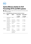
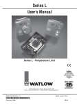
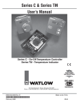
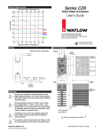
TLM-8
User’s Guide
Watlow Controls
1241 Bundy Blvd., Winona, MN 55987
Customer Service
Phone: 1-800-414-4299
Fax: 1-800-445-8992
Technical Support
Phone: (507) 494-5656
Fax: (507) 452-4507
Features and Description
The TLM-8 is a multi-zone temperature limit switch.
For thermal system safety, the TLM-8 can satisfy the
requirement for independent temperature monitoring.
The TLM-8’s alarm outputs interface with visual and
audible alarm devices, or they can initiate safe shutdown of equipment.
E-mail: [email protected]
Relays that open on alarm are consistent with fail safe
designs and practices. Alarms are acknowledged with
an optically isolated, digital input. Another isolated
digital input is used for testing, by simulating alarms
on all channels.
4FOTPS*OQVUT
The TLM-8 has the following features:
• Multi-channel temperature monitoring
• Latching alarms
• Isolated sensor inputs
• Support for various thermocouples, RTDs, and
thermostats
• Diagnostic test mode
• Open-sensor fail-safe
• Compact and easy to install
• LED indicator lights
Up to eight temperature zones may be monitored. If
any temperature exceeds a trip point, the TLM-8 generates an alarm output. The alarm output may be used
for safety shutdown or annunciation. Alarm outputs
remain active until two conditions are met in sequence:
the temperature drops below the trip point and alarms
are acknowledged. Built-in indicator lights show power
and alarm states.
The TLM-8 accepts up to eight thermocouple, RTD or
thermostatic switch temperature sensors. There are
two global alarm relay outputs. The TLM-8 is also
available with eight channel-alarm relays in addition
to the two global relay outputs. If all temperatures are
below the trip point, the TLM-8’s relay outputs are
closed. When alarms activate, the relay contacts open.
0QUJPOBM/0
$IBOOFM3FMBZ0VUQVUT
545"$,*OQVUT
5-.
5IFSNBM-JNJU.POJUPS
)FBUFS1PXFS
*OUFSMPDLT"MBSN
"OVODJBUJPO
1-$FUD
/0(MPCBM3FMBZ0VUQVUT
1PXFS
TLM-8 System Diagram
Warranty
The TLM-8 is manufactured by ISO 9001-registered
processes and is backed by a three-year warranty to
the first purchaser for use, providing that the units
have not been misapplied. Since Watlow has no control
over their use, and sometimes misuse, we cannot guarantee against failure. Watlow’s obligations hereunder,
at Watlow’s option, are limited to replacement, repair,
or refund of purchase price, and parts which upon
examination prove to be defective within the warranty
period specified. This warranty does not apply to damage resulting from transportation, alteration, misuse or
abuse. The purchaser must use Watlow parts to maintain all listed ratings.
Part No. 0600-2150-2000 Rev. D
Revised: October 2007
© 2004, 2007 Watlow Electric and Manufacturing Company. All
rights reserved.
WATLOW TLM-8 User’s Guide
1
Mounting the TLM-8
Wiring Recommendations
The TLM-8 mounts directly to a panel or on a DIN rail
depending on the mounting style ordered.
DIN Rail Mounting
The TLM-8 simply snaps onto a standard 35 mm DIN
rail. Place the hook side of the mounting mechanisms
over one of the DIN rail edges and snap the assembly
over the other edge.
DIN Rail Removal
Remove the TLM-8 from the DIN rail by placing a flat
blade screw driver through the slot in the end plate,
hook the blade into the snap latch and pry the snap
latch away from the DIN rail edge. Repeat for the other
side.
TB5 Sensor Inputs
Terminals
Sensor
Input
+
-
1
1
2
2
3
4
3
5
6
4
7
8
TB6 Power and Digital
Inputs
Terminals
Function
5
9
10
+
-
6
11
12
Test
1
2
7
13
14
Acknowledge
3
4
8
15
16
Power
5
6
Positive Terminals
Negative Terminals
92 mm (3.61 in)
Channel 1
Channel 2
.
.
.
.
Channel 7
Channel 8
TST- ACK- V-
TST
ACK
Power
2
8
J5 1
SENSOR
3
48 mm
(1.87 in)
4
Sensor
Inputs
5
6
7
+
20 mm
(0.75 in)
End View
J6
Isolated
DC Power
supply
_
236 mm (9.30 in)
Test and
Acknowledge Circuits
Input Wiring
DC Power Supply
The TLM-8 accepts 12 to 24VÎ (dc) power input from a
class 2 power supply.
Side View
NNJO
NN
JO
Test Input
NN
JO
NN
JO
The test input, TST, is a level-triggered digital input. It
is activated after the input signal is applied for at least
1 second (filter). The input signal may be generated by
a contact closure or controller output. The input accepts
a 5 to 30VÎ (dc) signal. The circuit contains a resistor
and optical isolator.
NN
JO
6TFS4VQQMJFE
$POUBDU
Mounting Hole Dimensions
Panel Mounting
%$
1PXFS
4VQQMZ
@
The four mounting holes will accommodate up to 3.8
mm (#6) screws or bolts.
5-.*OUFSOBM$JSDVJU
545
545m
Test Input
2
WATLOW TLM-8 User’s Guide
Acknowledge Input
The acknowledge input, ACK is an edge-triggered digital input. The input accepts a 5 to 30VÎ (dc) signal.
The circuit contains a resistor and optical isolator. If
you are using a push button to generate the input signal, momentary contacts are recommended because the
input is edge-triggered.
User Supplied
Contact
TLM-8 Internal Circuit
ACK+
+
DC
Power
Supply
You must connect the thermocouple to the input terminal
blocks correctly. If the inputs are reversed, the sensor
may be unable to generate an alarm. This could result
in a fire or other accident leading to loss of property or
lives.
ÓCAUTION:
To protect the alarm relay contacts when connected to an
inductive load, use catch diodes for dc loads and snubbers on ac or dc loads. For dc applications select a diode
with a reverse breakdown voltage 10 times the applied
voltage and forward load current.
ACK–
_
ÓWARNING:
Acknowledge Input
Load
NOG1 NOG2
J2
OUTPUTS
Be sure to use the type of sensor that matches your
TLM-8; the input type is noted on the label.
CH1CH2CH3 CH4CH5CH6CH7 CH8
J1
Thermocouple and RTD Inputs
Back EMF Clamp
Load
Back EMF Clamp
Thermostatic Switch Inputs
When using thermostatic switch (thermostat) inputs,
TLM-8 trip points can be set externally. The TLM-8
should be configured for thermostatic switches. Use
normally-closed thermostats that open at or above the
trip point.
Unused Inputs
If a sensor input is not used, short the positive and
negative input terminals.
TB1 Channel Relay Outputs
Relay Output
Terminals
1
1, 2
2
3, 4
3
5, 6
4
7, 8
5
9, 10
Wiring Recommendations for relay outputs
ÓCAUTION:
To minimize the power dissipated by the internal circuits
and ensure temperature accuracy, apply voltage to the
ACK and TST inputs only when intending to test the TLM-8
or acknowledge alarms. At other times the applied signal
should be 0VÎ (dc).
NOTE: To avoid interference with sensor readings, separate sensor and power wiring.
NOTE: This device is designed for indoor use only.
TB2 Global Relay Outputs
6
11, 12
Global Alarm
Output
7
13, 14
1
1, 2
8
15, 16
2
3, 4
Terminals
NOTE: Use only copper conductors for power and signals
other than thermocouples.
NOTE: Previous versions of the TLM-8 recommended
earth grounding the unit’s case, but the current version
does not require the case to be earth grounded.
NOTE: Alarm outputs and indicators are latched until the
condition is corrected and the alarm is acknowledged, as
long as the TLM-8 remains powered. If power is cycled to
the unit, it will evaluate the limits again.
WATLOW TLM-8 User’s Guide
3
Using the TLM-8
Sensor Types
J5 1
SENSOR
Channel 1
Channel 2
.
.
.
.
.
Channel 7
Channel 8
Power
2
Sensor types for the TLM-8 are factory configured; the
type of sensor for your TLM-8 is marked on the label.
Indicator
Lights
3
4
5
Trip Points
6
7
8
J6
TST- ACK- V-
Your TLM-8 has been factory configured with trip
points per your specification. Accuracy of a trip point
is ± 5% for TLM-8s with model numbers starting with
“TLME.” For example, 5% of a 200°C trip point is 10°.
So a 200°C trip point would trigger between 190 and
210°C.
Reading Trip Points
The trip points for TLM-8s with model numbers starting with “TLME” are encoded in the part number. To
determine trip points from a part number, see the section, TLM-8 Part Numbers. The trip points for TLM-8s
with model numbers starting with “TLMC” are listed
on the label.
Alarms and Acknowledgment
When the TLM-8 is powered and there is no alarm,
the alarm relay contacts are held closed. When a channel’s temperature exceeds the trip point or the sensor
fails, that channel’s indicator light is illuminated and
the global alarm relay contacts open.
When the TLM-8 is configured with the eight, optional
channel alarm relays and a channel’s temperature
exceeds its trip point, both the global alarm relay and
the corresponding channel alarm relay open.
All alarms are acknowledged with the ACK input. An
external device provides the logic signal to the ACK
input. The ACK input activates on the trailing edge of
the input signal. The input must be high for at least
20 milliseconds; when the input signal transitions to
low, alarms are acknowledged. Allow up to 3.5 seconds
after acknowledging the alarms for the relays to close.
Acknowledging alarms before the temperature drops
below the trip point or before a failed sensor is
repaired will have no effect. Wait until the temperature drops below the trip point before acknowledging
alarms. When the alarms are successfully acknowledged, the alarm indicator lights turn off and the
alarm relay contacts close.
Reading the Indicator Lights
Alarm Status Indicator Lights
Testing the Outputs
The TLM-8 TST digital input allows users to simulate
excessive temperature on all channels. An external
device — switch or controller — provides the logic signal to the test, TST, input. All channels go into alarm
which can be easily verified by the channel indicator
lights. Use the following procedure to test the TLM-8:
1. Activate the TST input for at least 1 second. All
alarms and indicator lights should activate.
2. Deactivate the TST input.
3. Activate the ACK input for at least 20 milliseconds.
4. Deactivate the ACK input. All alarms should deactivate within 3.5 seconds.
Changing Trip Points
To change a trip point on the TLM-8, obtain an RMA
number from your supplier and return the TLM-8 for
adjustment.
Maintenance
Over-temperature conditions may not occur regularly.
To test the TLM-8’s outputs, use the procedure in the
section “Testing the Outputs” to force the TLM-8 to
simulate alarm conditions on all channels.
To test trip point values and other system components,
use a thermocouple calibrator or other appropriate
means to simulate a sensor input above the trip point.
The alarm status of each channel is indicated by the
red indicator lights adjacent to the sensor input terminal block. A channel indicator light turns on when
the associated channel goes into alarm. If the TLM-8
is configured with channel relays, this indicator light
reflects the status of the associated channel relay. The
indicator light will remain on until the acknowledge
input, ACK, is activated after the temperature drops
below the trip point.
The green power light indicates the TLM-8 has power.
4
WATLOW TLM-8 User’s Guide
Application Example
Declaration of Conformity
In the following example, a TLM-8 monitors temperatures and provides independent safety shutdown, alarm
annunciation and acknowledgment. A multi-loop controller, CLS200 or MLS300, is used for primary control.
The TLM-8 has its own set of thermocouples to monitor
temperatures independent of the controller. If a temperature exceeds a trip point configured in the TLM8, then power to the heater is turned off by a TLM-8
controlled relay, and the System OK indicator light is
turned off. After the temperature drops and the cause
of the alarm has been corrected, an operator acknowledges the alarm. The primary controller resumes control of the loop(s).
Solid-state
Relay
AC
relay contacts
(normally open)
heater
CLS/MLS Multi-Loop
Temperature Controller
DC Power
Supply
ACK
Watlow Winona, Inc.
1241 Bundy Blvd.
Winona, MN 55987 USA
Declares that the following product:
Designation:
Series TLM-8
Model Numbers:
Classification:
TLM (C, E or P)(0 – 6)(0 or 1)(0 – 9)(additional letters or numbers indicating setpoint temperatures.
Temperature control, Installation Category II, Pollution degree 2
Rated Voltage and Power:
Control 12 to 24 VÎ (dc) 400 mA maximum
Note: Use of external CE approved ELV (UL Class 2) power supply required.*
Meets the essential requirements of the following European Union Directives by using the relevant standards show below to indicate
compliance.
2004/108/EC Electromagnetic Compatibility Directive
EN 61326
1997
A1:1998
A2:2002
A3:2004
Electrical equipment for measurement, control and laboratory use – EMC
requirements (Industrial Immunity, Class B Emissions).
EN 61000-4-2
1995
A2, 2001
Electrostatic Discharge Immunity
EN 61000-4-3
EN 61000-4-4
EN 61000-4-5*
2002
2004
1995
A2, 2001
Radiated Field Immunity
Electrical Fast-Transient / Burst Immunity
Surge Immunity
EN
EN
EN
EN
1996
2004
2001
1995
61000-4-6
61000-4-11*
61000-3-2*
61000-3-3*
A3, 2005
ED.2.
A2:2002
Conducted Immunity
Voltage Dips, Short Interruptions and Voltage Variations Immunity
Harmonic Current Emissions
Voltage Fluctuations and Flicker
73/23/EEC Low-Voltage Directive
EN 61010-1
2001
Safety Requirements of electrical equipment for measurement, control and laboratory use.
Part 1: General requirements
2002/96/EC WEEE Directive
thermocouples
TST
Series TLM-8
TLM-8 Thermal
Limit Monitor
System OK
indicator light
Equipment Requires Recycling
Raymond D. Feller III
Winona, Minnesota, USA
Name of Authorized Representative
Place of Issue
General Manager
August 2007
Title of Authorized Representative
Date of Issue
relay
coil
Signature of Authorized Representative
-
+
DC Power
Supply
Example Schematic
Declaration of Conformity
NOTE: Relay contacts are illustrated in the unpowered or
alarmed state.
WATLOW TLM-8 User’s Guide
5
TST Input
Specifications
Analog Inputs
Sensor input channels: 8
Sensor Types and Trip Point Ranges:
• 2-Wire 100 Ω Platinum RTD DIN curve (385): -100 to
850°C (-148 to 1,562°F)
• E Thermocouple: 100 to 801°C (212 to 1,474°F)
• K Thermocouple: 100 to 1,205°C (212 to 2,201°F)
• S Thermocouple: 500 to 1,711°C (932 to 3,112°F)
• J Thermocouple: 100 to 754°C (212 to 1,389°F)
• R Thermocouple: 500 to 1,720°C (932 to 3,128°F)
• T Thermocouple: 100 to 384°C (212 to 723°F)
• Thermostatic switch
At actual temperatures of -100°C (-148°F) or less, nuisance
alarms may occur.
Accuracy for trip points above 100°C (212°F):
• For part numbers starting with “TLME,” ± 5% of trip
point.
• For part numbers starting with “TLMC,” see below.
Sensor (s)
Trip Point Accuracy
Ambient: 15 to 35ºC
(59 to 95ºF)
Trip Point Accuracy
Ambient: 0 to 60ºC
(32 to 140ºF)
J, K, E, T, RTD
±0.5% of trip point and
±2ºC (3.2ºF)
±0.5% of trip point and
±4ºC (7.2ºF)
S, R
±0.5% of trip point and
±3ºC (5.4ºF)
±0.5% of trip point and
±5ºC (9ºF)
Repeatability: better than 5°C (9°F) or accuracy for trip
point, whichever is less.
Input filter: 1 second (minimum time the over-temperature
condition exists before the output responds)
Isolation:
• Common Mode: ± 10VÅ (ac) or VÎ (dc)
(Input to analog common)
• Input-to-Input: ± 10VÅ (ac) or VÎ (dc)
• Input-to-Frame Ground: ± 500VÅ (ac) or VÎ (dc)
ACK Input
Function: alarm acknowledge
Type: digital input
Activation: edge triggered (on to off transition)
Filter: 20 milliseconds
Maximum time to reset relays: 3.5 seconds
Maximum time signal should be held high: 5 seconds
Isolation: optical
Voltage and current: 5 to 30VÎ (dc); 2 mA @ 5VÎ (dc); 19
mA @ 30VÎ (dc)
Impedance: 1.5 kΩ
6
Function: test
Type: digital input
Activation: level triggered (signal high)
Filter: must be active for 1 second for valid simulation
Maximum time signal should be held high: 5 seconds
Isolation: optical
Voltage and current: 5 to 30VÎ (dc); 2 mA @ 5VÎ (dc); 19
mA @ 30VÎ (dc)
Impedance: 1.5 kΩ
Electromechanical Alarm Relays
Contact arrangement: open in power-off condition
Contact action: latch open in alarm condition
Maximum contact rating: 1 A @ 30VÎ (dc)
Indicator Lights
Alarm status: 8 red
Power: 1 green
Dimensions
Length: 236 mm (9.30 in.)
Width: 92 mm (3.61 in.)
Depth: 48 mm (1.87 in.)
DIN rail mount: add 20 mm (0.75 in.) to depth
Power Requirements
Nominal voltage: 12 to 24VÎ (dc)
Absolute voltage: 10 to 27VÎ (dc)
Power: 3.2 watts
Requires: Class 2 power supply
Terminal Blocks
Type: Removable
Torque: 0.33 to 0.35 Nm (2.9 to 3.1 in-lbs.)
Wire Gauge: 26 to 18 AWG
Environmental
Operating ambient temperature: 0 to 60°C (32 to 140°F)
Storage ambient temperature: -20 to 100°C (-4 to 212°F)
Relative humidity: 0 to 95%, non condensing
Agency Approvals / Compliance
UL, cUL Listed (File No. E185611)
• Process Control Equipment UL 61010
• Process Control Equipment C22.2 #61010-1
FM
• Temperature Limit Switches – Non Indicating Class 3545
• Temperature Supervisory Switch Class 3545
CE
• Low Voltage Directive (LVD) 73/23/EEC
• Electromagnetic Compatibility Directive (EMC) 2004/108/
EC
WATLOW TLM-8 User’s Guide
TLM-8 Part Numbers
Use the tables to determine the characteristics of your
TLM-8 based on its part number.
Custom TLM-8 Part Number
Standard TLM-8 Part Number
T L M C – __ __ __ 0 - 0 _ _ _
T L M E __ __ __ __ __ __ __ __ __ __ __
Sensor Type
0
RTD or Thermostat
1
Type E Thermocouple
2
Type J Thermocouple
3
Type K Thermocouple
4
Type R Thermocouple
5
Type S Thermocouple
6
Type T Thermocouple
Sensor Type
0
RTD or Thermostat
1
Type E Thermocouple
2
Type J Thermocouple
3
Type K Thermocouple
4
Type R Thermocouple
5
Type S Thermocouple
6
Type T Thermocouple
Alarm Relays
0
Global relays only
1
Global and 8-channel alarm relays
Alarm Relays
0
Global relays only
1
Global and 8-channel alarm relays
Mounting
0
Panel
1
DIN Rail
Mounting
0
Panel
1
DIN Rail
Trip Point (Channels 1 through 8)
Custom Code
(See Trip Point table below.)
3-digit code assigned by factory (See label on unit for trip-point values.)
Trip Points
RTD
E Thermocouple
J Thermocouple
K Thermocouple
R Thermocouple
S Thermocouple
T Thermocouple
Trip
Trip
Trip
Trip
Trip
Trip
Trip
Temperature
Temperature
Temperature
Temperature
Temperature
Temperature
Temperature
Point
Point
Point
Point
Point
Point
Point
Unused Input
A
Unused Input
A
Unused Input
A
Unused Input
A
Unused Input
A
Unused Input
A
Unused Input
A
103°C (217°F)
B
101°C (214°F)
B
100°C (212°F)
B
100°C (212°F)
B
501°C (934°F)
B
506°C (943°F)
B
100°C (212°F)
B
121°C (250°F)
C
202°C (396°F)
C
152°C (307°F)
C
150°C (302°F)
C
602°C (1,116°F)
C
601°C (1,114°F)
C
202°C (396°F)
C
D
E
151°C (304°F)
D
302°C (576°F)
D
202°C (396°F)
D
200°C (392°F)
D
708°C (1,306°F)
D
700°C (1,292°F)
D
291°C (556°F)
215°C (419°F)
E
403°C (756°F)
E
251°C (484°F)
E
252°C (486°F)
E
800°C (1,472°F)
E
810°C (1,490°F)
E
384°C (723°F)
F
902°C (1,656°F)
F
324°C (615°F)
F
502°C (936°F)
F
302°C (576°F)
F
303°C (577°F)
F
903°C (1,657°F)
404°C (759°F)
G
600°C (1,112°F)
G
350°C (662°F)
G
353°C (667°F)
G
999°C (1,830°F)
G
1,005°C (1,841°F)
G
478°C (892°F)
H
702°C (1,296°F)
H
402°C (756°F)
H
401°C (754°F)
H
1,100°C (2,012°F)
H
1,110°C (2,030°F)
H
584°C (1,083°F)
I
801°C (1,474°F)
I
450°C (842°F)
I
455°C (851°F)
I
1,206°C (2,203°F)
I
1,210°C (2,210°F)
I
J
1,306°C (2,383°F)
J
1,313°C (2,395°F)
J
K
1,404°C (2,559°F)
K
708°C (1,306°F)
J
502°C (936°F)
J
504°C (939°F)
824°C (1,515°F)
K
554°C (1,027°F)
K
556°C (1,033°F)
K
1,410°C (2,570°F)
Thermostat
K
600°C (1,112°F)
L
603°C (1,117°F)
L
1,497°C (2,727°F)
L
1,500°C (2,732°F)
L
653°C (1,207°F)
M
651°C (1,204°F)
M
1,593°C (2,899°F)
M
1,600°C (2,912°F)
M
704°C (1,299°F)
N
701°C (1,294°F)
N
1,720°C (3,128°F)
N
1,711°C (3,112°F)
N
754°C (1,389°F)
O
753°C (1,387°F)
O
WATLOW TLM-8 User’s Guide
807°C (1,485°F)
P
851°C (1,564°F)
Q
907°C (1,665°F)
R
952°C (1,746°F)
S
998°C (1,828°F)
T
1,057°C (1,935°F)
U
1,101°C (2,014°F)
V
1,157°C (2,115°F
W
1,205°C (2,201°F)
X
7
How to Reach Us
Corporate Headquarters
Europe
Watlow Electric Manufacturing Company
12001 Lackland Road
St. Louis, MO 63146
Sales: 1-800-WATLOW2
Manufacturing Support: 1-800-4WATLOW
Email: [email protected]
Website: www.watlow.com
From outside the USA and Canada:
Tel: +1 (314) 878-4600
Fax: +1 (314) 878-6814
Watlow France SARL
Immeuble Somag
16, Rue Ampère
95307 Cergy-Pontoise CEDEX
France
Tel: + 33 (0)1 30 73 24 25
Fax: + 33 (0)1 30 73 28 75
Email: [email protected]
Website: www.watlow.fr
Latin America
Watlow de México S.A. de C.V.
Av. Fundición No. 5
Col. Parques Industriales
Querétaro, Qro. CP-76130
Mexico
Tel: +52 442 217-6235
Fax: +52 442 217-6403
Watlow GmbH
Postfach 11 65, Lauchwasenstr. 1
D-76709 Kronau
Germany
Tel: +49 (0) 7253 9400-0
Fax: +49 (0) 7253 9400-900
Email: [email protected]
Website: www.watlow.de
Watlow Italy S.r.l.
Viale Italia 52/54
20094 Corsico MI
Italy
Tel: +39 024588841
Fax: +39 0245869954
Email: [email protected]
Website: www.watlow.it
Watlow Ibérica, S.L.U.
CME - Avda. de la Vía Láctea, s/n. Oficina 24
28830 - San Fernando de Henares Madrid
Spain
Tel: +34.91.675.1292
Fax: +34.91.648.7380
Email: [email protected]
Website: www.watlow.es
Watlow
Storgatan 24
302 43 Halmstad
Sweden
Tel: + 46 (0)35 27 11 66
Fax: +46 (0)35 27 11 67
Email: [email protected]
Website: www.watlow.se
Watlow UK Ltd.
Linby Industrial Estate
Linby, Nottingham, NG15 8AA
United Kingdom
Telephone: (0) 115 964 0777
Fax: (0) 115 964 0071
Email: [email protected]
Website: www.watlow.co.uk
From outside The United Kingdom:
Tel: +44 115 964 0777
Fax: +44 115 964 0071
Asia and Pacific
Watlow Singapore Pte Ltd.
16 Ayer Rajah Crescent,
#06-03/04,
Singapore 139965
Tel: +65 6773 9488
Email: [email protected]
Fax: +65 6778 0323
Website:www.watlow.com.sg
Watlow Korea Co., Ltd.
#1406, E&C Dream Tower, 46, Yangpyeongdong-3ga
Yeongdeungpo-gu, Seoul 150-103
Republic of Korea
Tel: +82 (2) 2628-5770
Fax: +82 (2) 2628-5771
Website: www.watlow.co.kr
Watlow Australia Pty., Ltd.
4/57 Sharps Road
Tullamarine, VIC 3043
Australia
Tel: +61 3 9335 6449
Fax: +61 3 9330 3566
Website: www.watlow.com
Watlow Malaysia Sdn Bhd
No. 14-3 Jalan 2/114
Kuchai Business Centre
Jalan Kuchai Lama
58200 Kuala Lumpur
Malaysia
Tel: +60 3 7980 7741
Fax: +60 3 7980 7739
瓦特隆电子科技(上海)有限公司
(销售办事处)
上海市浦东新区张江工业园区碧波路115号572弄22棟 *
邮编: 201203
传真: 86 21 5080-0906
电话: 86 21 5080-0902
电子邮箱: [email protected] Website: www.watlow.cn
瓦特龍電機股份有限公司
80143 高雄市前金區七賢二路189號 10樓之一
傳真: 07-2885568
電話: 07-2885168
Watlow Electric Manufacturing (Shanghai) Company
115-22#, 572nd Lane, Bibo Road, Zhangjiang High-Tech Park,
Shanghai, PRC 201203
People’s Republic of China
Tel: +86 21 5080-0902
Fax: +86 21 5080-0906
Email: [email protected]
Website: www.watlow.cn
ワトロー・ジャパン株式会社
〒101-0047 東京都千代田区内神田1-14-4
四国ビル別館9階
Tel: 03-3518-6630
Email: [email protected]
Fax: 03-3518-6632
Website: www.watlow.co.jp
Watlow Japan Ltd.
1-14-4 Uchikanda, Chiyoda-Ku
Tokyo 101-0047
Japan
Tel: +81-3-3518-6630
Fax: +81-3-3518-6632
Email: [email protected]
Website: www.watlow.co.jp
Revised: September 20, 2007
Watlow Electric Taiwan Corporation
10F-1 No.189 Chi-Shen 2nd Road Kaohsiung 80143
Taiwan
Tel: +886-7-2885168
Fax: +886-7-2885568
Your Authorized Watlow Distributor