1
Specifications
Input
Parameter
Voltage
Input type
Crest factor 3
Floating input
Resistive potential division method
1.5/3/6/10/15/30/60/100/150/300/600/1000V
Crest factor 6
750m/1.5/3/5/7.5/15/30/50/75/150/300/500V
Direct input:5m/10m/25m/50m/100m/250m/500m/1/2.5A Direct input:0.5/1/2.5/5/10/25A
External input:25m/50m/125m/250m/500m/1.25/2.5/5V
External input:25m/50m/125m/250m/500m/1.25/2.5/5V
Instrument loss
(input resistance)
Approximately 2MΩ
Direct input: Approximately 100mΩ +
Approximately 0.07µH
External input: Approximately 100kΩ
Instantaneous maximum
allowed input (1 cycle, 20ms
duration)
Peak voltage of 4 kV or rms of 1.5 kV
(whichever is lower)
Peak current of 30 A or rms of 15 A (whichever is lower) Peak current of 450 A or rms of 300 A (whichever is lower)
External input: Peak not to exceed 10 times
External input: Peak not to exceed 10 times
range-value
range-value
Continuous maximum allowed
input
Peak voltage of 1.5 kV or rms of 1 kV
(whichever is lower)
Peak current of 10 A or rms of 7 A (whichever is lower)
External input: Peak not to exceed 5 times
range-value
Continuous maximum common
mode voltage (50/60Hz)
600 Vrms CATII
Influence from common mode
voltage
With voltage input terminals shorted and current input terminals open (50/60 Hz): ±0.01% of rng or less (±(0.01 × 15/(rated value of rng))% of
rng or less for 10-V rng or less).
Reference value up to 100 kHz: ±(0.1 × f% of rng) or less, (±(0.1 × f × 15/(rated value of rng))% of rng or less for 10-V range or less), but no less
than 0.01% Or, two times these values for crest factor 6. ; frequency unit: kHz
Input terminal type
Plug-in terminal (safety terminal)
A/D converter
Voltage/current input simultaneous conversion, 16-bit resolution, conversion speed (sampling period) of approximately 5 µsec
Switching range-value
Auto-range function
Range-value can be set independently for each element, through manual setting, automatic setting, or online setting
Increasing range-value: Range-value is increased when rms exceeds 110% of rated value or peak value exceeds approximately 330% (or 660%
for crest factor 6) of rated value.
Decreasing range-value: Range-value is decreased when peak is 300% (or 600% or less for crest factor 6) or less of lower range-value while rms
is 30% or less of rated value.
Rated value
(range-value)
Current (5A input element)
Current (50A input element)
Shunt input method
Direct input:10m/20m/50m/100m/200m/500m/1/2/5A Direct input:1/2/5/10/20/50A
External input:50m/100m/250m/500m/1/2.5/5/10V
External input:50m/100m/250m/500m/1/2.5/5/10V
Direct input: Approximately 2mΩ +
Approximately 0.07µH
External input: Approximately 100kΩ
Peak current of 150 A or rms of 50 A (whichever is lower)
External input: Peak not to exceed 5 times
range-value
Direct input: Large binding post
External input: BNC connector (insulation type)
Measurement Functions
Method
Digital multiplication method
Temperature: 23 ± 3˚C
Crest factor 3: Up to 300 (in the valid input range). 3 (when inputting rated values of the measuring range). However, 2 for the 1000 V range.
Crest factor 6: Up to 600 (in the valid input range). 6 (when inputting rated values of the measuring range). However, 4 for the 500V range.
Accuracy
Frequency
Voltage/Current Accuracy: ± (reading error + measurement range error) Power Accuracy: ± (reading error + measurement range error)
Conditions
DC
0.1% of rdg + 0.2% of rng
0.1% of rdg + 0.2% of rng
Temperature: 23 ±3°C
0.5 Hz ≤ f < 10 Hz
0.1% of rdg + 0.2% of rng
0.2% of rdg + 0.3% of rng
Humidity: 30 to 75%RH
10
Hz
≤
f
<
45
Hz
0.1%
of
rdg
+
0.1%
of
rng
0.1% of rdg + 0.2% of rng
Input waveform: Sine
45 Hz ≤ f ≤ 66 Hz
0.1% of rdg + 0.05% of rng
0.1% of rdg + 0.05% of rng
wave
Common mode
66 Hz < f 1 kHz
0.2% of rdg + 0.1% of rng
0.1% of rdg + 0.1% of rng (Voltage, 5A input element current
voltage: 0 V
direct input and external input)
Line filter: OFF
0.2% of rdg + 0.1% of rng (50A input element current direct input)
Power factor: cosø = 1 1 kHz < f ≤ 50 kHz
0.3% of rdg + 0.2% of rng (Voltage, 5A input element current
0.3% of rdg + 0.1% of rng (Voltage, 5A input element current
After warm up time has
direct input)
direct input)
passed
(0.02 × f + 0.3)% of rdg + 0.2% of rng (External input)
(0.015 × f + 0.3)% of rdg + 0.1% of rng (External input)
Wired condition after
(0.1 × f + 0.2)% of rdg + 0.1% of rng (50A input element current direct input) (0.1×f+0.2)% of rdg + 0.2% of rng (50A input element current direct input)
zero level
50 kHz < f ≤ 100 kHz
0.6% of rdg + 0.2% of rng (Voltage, 5A input element current
0.7% of rdg + 0.3% of rng (5A input element current direct
compensation or range
direct input)
input)
value change
(0.009 × f + 0.6)% of rdg + 0.2% of rng (External input)
(0.009 × f + 0.9)% of rdg + 0.3% of rng (External input)
3-month after calibration
(0.1 × f +0.2)% of rdg + 0.2% of rng (50A input element current direct input) (0.3×f-9.5)% of rdg + 0.3% of rng (50A input element current direct input)
Unit for f in accuracy
100 kHz< f ≤ 500 kHz
0.006*f% of rdg + 0.5% of rng (Voltage, 5A input element current 0.008*f% of rdg + 1% of rng (5A input element current direct
calculation
direct input)
input)
formula is kHz
(0.06 × f - 4)% of rdg + 1% of rng (External input)
(0.03 × f-1.5)% of rdg + 0.5% of rng (External input)
500 kHz< f ≤ 1 MHz
(0.048 × f - 20) of rdg + 2% of rng
(0.022 × f-8) of rng + 1% of rng (Voltage, 5A input element
(5A input element current direct input)
current direct input)
Power factor influence
When cos ø = 0, 45 Hz to 66 Hz: 0.15% of apparent power reading is added to the above power accuracy. For other frequencies: Reference value
Ø is phase angle
For 5 A input element current direct input, add (0.15 + 0.05 × f)% of apparent power reading to the above accuracy.
between voltage and
For 50 A input element current direct input, add (0.15 + 0.3 × f)% of apparent power reading to the above accuracy.
current
For external input, add (0.15 + 0.1 × f)% of apparent power reading to the above accuracy.
When 0 < cos ø < 1, add (tan ø × (influence of power factor = 0)) of power reading.
Effective input range
Voltage, current: Rms and AC: 1% to 110% of rated range-value, DC: 0% to ±110% of rated range-value, Mean: 10% to 110% of rated range-value
Power: DC measurement: 0% to ±110% of rated range-value, AC measurement: Up to ±110% of power range-value, with voltage and current within 1% to
110% of rated range-value (Sync source signal level must be 10% or more (20% or more for crest factor 6) of rated range value)
Effective input is in the range up to 1000V at Voltage , 5A at 5A input element, 50A at 50A input element and 10V at External input.
Accuracy of crest factor 6 Add the accuracy of measurement range error ( three months accuracy of crest factor 3 after calibration) × 1 to the accuracy three months after
calibration.
One-year accuracy
Add the accuracy of reading error ( three months after calibration) × 0.5 to the accuracy three months after calibration.
Line filter function
Measurement can be made with a line filter inserted in the input circuit. Cutoff frequency (fc): 500 Hz or 5.5 kHz
Line filter on accuracy
Cut-off frequency of 500 Hz: Voltage, current: Add 0.2% of rdg in range of 45 to 66 Hz. Under 45 Hz, add 0.5% of rdg.
Power: Add 0.3% of rdg in range of 45 to 66 Hz. Under 45 Hz, add 1% of rdg.
Cutoff frequency of 5.5 kHz: Voltage, current: Add 0.2% of rdg under 66 Hz. At 66 Hz to 500 Hz, add 0.5% of rdg.
Power: Add 0.3% of rdg under 66 Hz. At 66 Hz to 500 Hz, add 1% of rdg.
Temperature coefficient ±0.03% of rdg/˚C at 5 to 20˚C and 26 to 40˚C
Conditions for detecting Lead and lag are detected correctly when the voltage and current signals are both sine waves, the lead and lag amplitude is greater than or equal to
lead and lag
50% (or 100% for crest factor 6) of the measurement range, the frequency is between 20 Hz to 10 kHz, and the phase angle is ±(5 to 175°). *1
Measurement lower limit Data update rate
50 msec
100 msec
200 msec
500 msec
1 sec
2 sec
5 sec
frequency
Measurement lower limit frequency
45 Hz
25 Hz
15 Hz
5 Hz
2.5 Hz
1.5 Hz
0.5 Hz
Current and power DC accuracy (5 A input element) -----Add 20 µA to current and 20 µA × (voltage reading) to power
Current and power DC accuracy (50 A input element) -----Add 1 mA to current and 1 mA × (voltage reading) to power
External input -----Add (0.05/scaling value) A to current and (0.05/scaling value) A × (voltage reading) to power
Zero level correction or as a zero level correction in current and power DC accuracy relating to temperature changes following range-value changes, add 10 µA /°C to current and add (10 µA × voltage reading) /°C to
power for the 5 A input element. For the 50 A input element, add 1 mA /°C to current and add (1 mA × voltage reading) /°C to power. For external input, add (0.05/scaling value) A/°C to current and add {(0.05/scaling
value) A × (voltage reading)} /°C to power.
Current rms, mean, AC-----Accuracy figures are specified with line filter turned ON for 2 mA or less on a 5 A input element, for 200 mA or less on a 50 A input element, for 10/(scaling value ) A or less on a external input.
Add (0.006 × I2)% at 5 A input element.
Add (0.00006 × I2)% at 50 A input element.
Add 0.1% of range if the display updating period is 50 msec.
All accuracy of 0.5 Hz to 10 Hz: Reference values
Voltage ----- Reference values in cases where f(Hz) × voltage(V) > 2.2 × 10 7 at 100 kHz or higher.
Current ----- Reference values for 20 AAC or higher (except for range of 50 Hz to 400 Hz) or higher
For currents less than 5 mA with frequencies above 1 kHz, the current accuracy and the power accuracy figures are the reference values.
Add 20% of rng to the accuracy above for the accuracy of the waveform display data, voltage peak (Upk), and current peak (Ipk) in the range up to 1 MHz. (Reference Value)
Effective input range of Upk and Ipk is within 300% (within ±600% for crest factor 6) in the range. However, within ±200% for the 1000 V range of crest factor 3 (within ±400% in the 500 V range of crest factor 6).
rdg: reading, rng: range
Maximum measurement value must be within maximum allowed input.
*1: Frequency is between 20 Hz to 1 kHz for 50 A input element.
1/4
Specifications
±(0.05% of reading + 1 digit)
Note: Within accuracy-assured range ±(0.05% of rdg
+ 1 digit) for the measurement function parameters.
Input signal level is greater than or equal to 0.6 V
(voltage input), 25 mV (external input), 5 mA (5-A
input element), or 150 mA (50-A input element) and
the signal is greater than or equal to 30% (from 0.5
Hz to less than 440 Hz, with zero crossing filter ON),
10% (from 440 Hz to 500 kHz), or 30% (from more
than 500 kHz to 1 MHz) of the measurement range.
However, input signal level is 2 times for crest factor 6.
OFF, 500 Hz
Accuracy
Calculation Functions
Three-phase, Three-phase,
Single-phase, three-wire
Three-phase,
three-wire
three-wire
four-wire
(2 voltage, 2 current) (3 voltage, 3 current)
Voltage ΣU
(U1+U2)/2
(U1+U2+U3)/3
Current ΣI
(I1+I2)/2
(I1+I2+I3)/3
Active power ΣP
Normal measurement Qi=
Reactive
power Q, ΣQ Harmonic measurement Qi
Apparent
power S, ΣS
Normal measurement
Harmonic measurement
Power factor Power factor
λ, Σλ
λ, Σλ
Phase angle Phase angle
φ, Σφ
φ, Σφ
Calculation precision
(of calculated values relative
to measured values)
(S2-P2)
Si=Ui × Ii
S1+S2
Si=
(ΣP2+ΣQ2)
(Pi2+Qi2)
3
2
λi=Pi/Si
ΣP/ΣS
φi=cos-1(Pi/Si)
φi=cos-1(ΣP/ΣS)
P1+P2
P1+P2+P3
Q1+Q2
Q1+Q2+Q3
(S1+S2)
3
3
(S1+S2+S3) (S1+S2+S3)
Apparent power (S) and reactive power (Q): ±0.001% of power range-value
Power factor (λ): ±0.0001
Phase angle (φ): ±0.005° relative to calculation from power factor
Note 1: Apparent power (S), reactive power (Q), power factor (λ), and phase angle (φ) for this equipment are calculated from active
power. (However, reactive power during harmonic measurement is the sum of every order.) Therefore, in the case of distorted-wave
input, these values may be different from those of other instruments based on different measurement principles.
Note 2: Since the phase is determined using the equation ø≥=W/VA, there is no rule for accuracy.
Note 3:The value of var in the É∞var calculation is calculated with a preceding minus sign (-) when the current input leads the voltage
input, and a plus sign when it lags the voltage input, so the value of É∞var may be negative.
Other parameters (during normal measurement)
Upk, Ipk (peak value), CF (crest factor), FF (form factor), |Z| (impedance), Rs and Rp (resistance), Xs and Xp (reactance), η and 1/η
(efficiency), Pc (Corrected Power), F1 to F4 (user-defined functions), delta calculations (three-phase three-wire_3V3A conversion, Y-∆
conversion, ∆-Y conversion)
Wiring settings: Settings can be divided into three groups (A, SB, and C).
Each group is selected from the following: 1P2W (single-phase two-wire, one element used), 1P3W (single-phase three-wire, two elements used), 3P3W (three-phase three-wire, two elements used), 3V3A (three-phase three-wire, three elements used), 3P4W (threephase four-wire, three elements used).
Display Functions
Display
Pixels in full screen:
Display type
Numerical values:
Waveforms:
Vector:
Bar:
Trend:
Data updating rate:
Display update rate
Max. Display
Min. Display
Response type:
Display scaling function:
6.4-inch color TFT LCD
640 × 480 (The LCD unit may contain defects of
approximately 0.02% in the pixels of the full screen)
Normal measurement: 4/8/16/42/78/ALL
Harmonic measurement:4/8/16/Single List/Dual
List
Single/Dual/Triad/Quad
Phase diagram for first-order components in harmonic measurement
Bar graph up to upper limit of analyzed orders in
harmonic measurement
Trend display of measured/calculated values
Selected from 50msec/100msec/200msec/
500msec/1sec/2sec/5sec. (waveform OFF)
However, Maximum data update is approximately
620ms when waveform data acquisition is ON.
Same as the data update rate. However, When
waveform data acquisition is OFF
Numeric display (16 or less value)
Maximum 100msec
The others display setting Maximum 200msec
Note: Data can be stored in the internal memory
every data update late
140% of the voltage and current range rating
Urms, Uac, Irms, and Iac are up to 0.3% relative to
the measuring range (or up to 0.6% for a crest factor of 6). Umn and Imn are up to 1% (or 2% for a
crest factor of 6). Below that, zero suppress. Current integration value q also depends on the current value.
Up to data updating rate × 2 (with waveform acquisition off)
PT ratio, CT ratio, and power scaling factor can be
scaled.
Averaging functions
Normal measurement
Methods: Exponential average or simple moving
average.
Exponential average:
Attenuation constant of 2, 4, 8, 16, 32, or 64
Moving average:
Number of averages (N) set to 8, 16, 32, 64, 128,
or 256
Harmonic measurement When using an exponential average, the attenuation constant is 5.625 if the frequency of the PLL
synchronization source is 55 Hz or greater but less
than 75 Hz; otherwise, the attenuation constant is
4.6875. (When data length = 8192)
Display resolution
U,I,P: During rated range-value input, the decimal
place and the counting unit are set so that the display does not exceed a count value of 60,000. ΣU,
ΣI, ΣP: The decimal place and the counting unit are
the same as for the maximum range-value of the calculated element.
Key lock function is available (version 3.21 and later)
Frequency Measurement Functions
Measurement input
Measurement method:
Frequency range
Select three of the following: U1,I1, U2,I2, U3,I3,
U4,I4, U5,I5, U6,I6
Reciprocal method
Data updating rate
Frequency range
50 msec
45 Hz f 1 MHz
100 msec
25 Hz f 1 MHz
200 msec
15 Hz f 500 kHz
500 msec
5 Hz f 200 kHz
1 sec
2.5 Hz f 100 kHz
2 sec
1.5 Hz f 50 kHz
5 sec
0.5 Hz f 20 kHz
However, measurement range is up to 100 kHz for
50A input element, up to 500 kHz for external input.
Zero cross filter
Integration Functions
The integrating functions do not work during waveform acquisition or in harmonic analysis mode ON.
Measured parameters:
Power (Wp), positive-only power (+Wp), negativeonly power (-Wp), current (q), positive-only current
(+q), negative-only current (-q) (For current integration, select only one of the following for each
element: rms, mean, DC, AC.), time (Time)
Mode
Standard integration mode (timer mode)
Continuous integration mode (repeat mode)
Manual integration mode
Individual element integration Integration can be started/stopped element by element using GP-IB or serial (RS-232) communications.
Timer
Integration can be stopped automatically according to a timer setting.
Setting range: 0000h00min00sec to
10000h00min00sec
Count overflow
If the integration value exceeds ± 999999
MWh(MAh), the elapsed time is saved and the operation is stopped.
Accuracy
±(unit accuracy + 0.05% of rdg)
Timer accuracy
±0.02%
Harmonic Measurement Functions
Measurements
Select one of the following: ΣA, ΣB, ΣC
Method
PLL synchronization or external sampling clock
Measurement frequency range PLL synchronization: Synchronization source fundamental frequency of 10 Hz to 1 kHz
External sampling clock: Fundamental wave of 0.5
Hz to 100 Hz (Input 2048 times the fundamental
frequency. The waveform is a square wave with a
duty cycle of 50% at the TTL level.)
Analyzed parameters
For each order: U, I, P, S, Q, λ, φ(U-I), φU, φI (phase
difference of harmonic component relative to fundamental wave), |Z|, Rs, Rp, Xs, Xp
Total: U, I, P, S, Q, λ, φ
Σ calculation of fundamental wave and total: U, I, P,
S, Q, and λ
For each order: Harmonic content of U, I, and P
THD of U, I, and P
UTHF (voltage telephone harmonic factor), ITHF
(current telephone harmonic factor), UTIF (voltage
telephone influence factor), ITIF (current telephone
influence factor), HVF (harmonic voltage factor),
HIF (harmonic current factor)
FFT data length
8192, 4096, or 2048
FFT processed word length 32 bits
Window function
Rectangular
Anti-aliasing filter
Set by line filter (fc = 5.5 kHz)
PLL synchronization
Fundamental
frequency (Hz)
Sampling
frequency
10 f< 20
20 f< 40
40 f< 75
75 f< 150
150 f< 440
440 f 1000
f
f
f
f
f
f
External sampling clock
Fundamental
frequency (Hz)
×
×
×
×
×
×
2048
1024
512
256
128
64
Window width relative to FFT data length
Maximum
(number of fundamental wave cycles)analyzed orders
8192
4096
2048
4
2
1
8
4
2
16
8
4
32
16
8
64
32
16
128
64
32
100
100
100
100
50
25
Window width relative to FFT data length
Maximum
(number of fundamental wave cycles)analyzed orders
8192
4096
2048
0.5 f 100
f × 2048
4
2
1
100
However, it is 1 f 100 when the FFT data length is 8192
Accuracy:±(reading error + measurement range error) (Line filter 5.5 kHz ON)
Voltage/Current
Power
0.5 Hz f < 10 Hz
0.4% of rdg + 0.2% of rng
0.7% of rdg + 0.3% of rng
10 Hz f < 45 Hz
0.4% of rdg + 0.1% of rng
0.6% of rdg + 0.2% of rng
45 Hz f 66 Hz
0.3% of rdg + 0.05% of rng
0.4% of rdg + 0.05% of rng
66 Hz < f 1 kHz
1% of rdg + 0.1% of rng
1.5% of rdg + 0.1% of rng
1 kHz < f 2.5 kHz
2% of rdg + 0.1% of rng
---------
Line filter OFF
Sampling
frequency
However, the amplitude level of the PLL source is 30%
of range or more (or 60% for a crest factor of 6).
Two times range error for crest factor 6.
During nth-order component input, add {(n/(m+1))/
50}% of the nth-order reading to (n-m)th order and
(n+m)th order.
For normal measurement accuracy, during nth-order
component input, add {(n/(m+1))/50}% of the nth-order reading to (n-m)th order and (n+m)th order.
Add (n/500)% of the nth-order reading to the nth-order component.
2/4
Waveform Display Functions
Data memory size
Vertical axis zoom
Waveform display format
Data interpolation
Cursor measurement
Motor Evaluation Functions (optional) (/MTR)
1 kW (Peak to peak compressed data)
0.1-100 times
1, 2, 3, or 4 split display
Dot or linear interpolation
When you place the cursor on the waveform, the
value of that point is displayed.
Triggers
Mode
Type
Source
Slope
Position
Sample rate
Time/Div
Auto/Normal
Edge
U1, I1, U2, I2, U3, I3, U4, I4, U5, I5, U6, I6, external
Rising/falling/both
0% (fixed)
Approximately 200 kHz
0.5 msec to 500 msec (not to exceed 1/10 of display updating period)
The frequency that allows displaying of waveforms is up to approximately 10 kHz.
Trend Display
Measurement item
Maximum 16 items
Horizontal axis
Normal (waveform OFF) 3/6/10/30sec/1/3/6/10/30min/1/3/6/12/24hour/div
Normal (waveform ON) 1 to 500 P/div (P/div is the number of data points
per grid section)
Harmonic measurement 1 to 500 Points/div (P/div is the number of data
points per grid section)
Scale
Auto/Manual
Internal Memory
Internal memory size
Store interval
Approximately 11 MB
Maximum 50msec (waveform OFF) to 99 hour 59
minutes 59 seconds.
* Store interval is maximum approximately 620ms
when waveform data acquisition is ON.
Guideline for Storage Time (Waveform Display OFF, Integration Function OFF)
channel number
3ch
3ch
6ch
6ch
items (each channel)
3
10
10
20
store interval
50ms
1 second
50ms
1 second
Measurable time
2 hours 50 minutes
22 hours
35 minutes
6 hours
The motor evaluation functions do not work in harmonic measurement mode.
Calculated parameters
Torque, rpms, mechanical power, synchronization
speed, slip, motor efficiency, total efficiency
Measured parameters
Analog input for calculating torque and rpms
Input resistance
Approximately 1MΩ
Accuracy
±(0.1% of rdg + 0.2% of rng)
Input range-values
1/2/5/10/20 V
Up to ±110% of range-value
Effective input range
Temperature coefficient ±0.03% of rng/°C
Pulse input for rpm calculation
Input resistance
Approximately 1MΩ
Accuracy
±0.05% of rdg + 1 mHz + 1 digit
Input range
±5 Vpk
Effective amplitude
1 Vp-p or higher
Input waveform
50% duty ratio rectangular wave
Frequency measurement range 2 Hz to 200 kHz
Built-in Printer (optional) (/B5)
Printing method
Dot density
Paper width
Effective recording width
Recorded information
Thermal line-dot
8 dots/mm
80 mm
72 mm
Screenshots, list of measured values, harmonic bar
graph printouts, settings
Ethernet (optional) (/C10)
Transmission method
Supported services
Ethernet (10BASE-T)
FTP server, FTP client, LPR (network printing),
SMTP (automatic mail transfer), DHCP, DNS
Electrical and mechanical specifications
As per IEEE802.3
Connector
RJ-45 connector
Other
Cannot be used for DIAdem and other protocols.
Built-in Hard Disk (optional) (/C10)
Capacity
SCSI ID
10 GB (2 GB×5) IBM format
4 (fixed)
External I/O
Note: Depending on the user-defined math, integration, and other settings, the actual measurement time may be shorter than stated above.
EXT CLK
D/A Output (optional) (/DA)
D/A conversion resolution
Response time
Output Voltage
Update interval
Number of outputs
Accuracy
Maximum output current
Temperature coefficient
Output format
Frequency
12 bits
At maximum, two times the display update rate.
±5VF.S for each rated value
Same as the data update rate on the main unit
30 parameters (each channel can be set separately)
±(display accuracy +0.2% of F.S.)(F.S. = 5 V)
±0.1 mA
±0.05% of F.S./°C
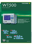
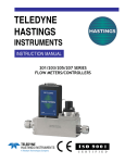
D/A output
Approximately
7.5 V
5.0V
2.5V
0.5V
0.5Hz
10Hz
100kHz
1kHz
1MHz
1Hz
100Hz
10kHz
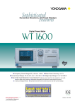
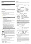
Integrated values
D/A output
Approximately
7.0 V
Display
value
140% of rated input
5.0V
Rated input
Integration
time
0
t0
t0 values
In standard integration/continuous integration modes: Timer set time
In manual integration mode: Integration D/A output set time
(Sync source during normal measurement, PLL
source or external sampling clock during harmonic
analysis)
Connector
BNC
Input voltage
TTL level
EXT MEAS.START
( ex t e r n a l m e a s u r e m e n t s t a r t I / O ) , E X T
MEAS.STOP (external measurement stop I/O)
Connector
BNC
Synchronized measurement Connect the EXT MEAS.START terminal of the
master unit with the EXT MEAS.START terminal
of the slave unit, and connect the EXT MEAS.STOP
ter minal of the master unit with the EXT
MEAS.STOP terminal of the slave unit.
Internal floppy drive
Size
3.5-inch
Format
1.44 MB
Communication functions
GP-IB or serial (RS-232) provided as a standard function.
GP-IB interface
Electrical and mechanical specifications
As per IEEE St’d 488-1978
Functional specifications
SH1, AH1, T6, L4, SR1, RL1, PR0, DC1, DT0, C0
Protocol: As per IEEE St’d 488.2 1992
Serial (RS-232) interface
Connector
D-Sub 9-pin
Specification
EIA-574 (specifications for 9-pin interface in EIA232 (RS-232) standard)
Transfer rate
1200, 2400, 4800, 9600, 19200 bps
VGA video output
Connector type
D-Sub 15-pin (VGA VIDEO OUT)
Output format
VGA-compatible
SCSI interface (optional)
Specification
SCSI(Small Computer System Interface)
ANSI X3.131-1986
Connector
D-sub half-pitch 50-pin (pin type)
Connector pin assignments Unbalanced (single-end), internal terminator
Other parameters
Display value
140%
100%
0%
-100%
-140%
Output
Approximately 7.0 V
5.0 V
0V
-5.0 V
Approximately -7.0 V
D/A output
Approximately 7.5 V
Approximately 7.0 V
5.0V
-140 -100
Note that PF and deg are not
output beyond the range of
±5.0 V. If an error occurs,
approximately ±7.5 V are
output.
0° to 360° are output at 0 to
5.0 V; LAG180° to LEAD180°
are output at -5.0 V to 5.0 V.
0
100 140 Display
value (%)
-5.0V
Approximately -7.0 V
Approximately -7.5 V
3/4
쐽Rack Mount
General Specifications
Complying standard EN61010-1
Overvoltage category (Installation category) II*2
Pollution degree 2 *3
Emission *1
Complying standard
EN61326 Class A
EN61000-3-2
EN61000-3-3
AS/NZS 2064 Class A
1
Complying standard
EN61326 Annex A*4
Immunity *
Warmup time
Approximately 1 hour
Operating temperature and humidity ranges
5 to 40°C, 20 to 80%RH when not using the printer,
5 to 40°C, 35 to 80%RH when using the printer.(no
condensation)
Storage temperature
-25 to 60°C (no condensation)
Operating elevation
2000 meters or less
Insulating resistance
50 MΩ or higher at 500 VDC
Between casing and power plug
Between voltage input terminals (ganged) and casing
Between current input terminals (ganged) and casing
Between voltage input terminals (ganged) and current input terminals (ganged)
Between input terminals of each element.
Between torque/speed input terminals (ganged) and casing
Between torque input terminals (ganged) and speed
input terminals (ganged)
Between input terminals of each element.
Withstand voltage
1500 VAC for one minute at 50/60 Hz
Between casing and power plug
3700 VAC for one minute at 50/60 Hz
Between voltage input terminals (ganged) and casing
Between current input terminals (ganged) and casing
Between voltage input terminals (ganged) and current input terminals (ganged)
Between input terminals of each element.
Rated supply voltage
100 to 120 VAC, 200 to 240 VAC (switches automatically)
Allowed supply voltage fluctuation range
90 to 132 VAC, 180 to 264 VAC
Rated supply frequency
50/60 Hz
Allowed supply frequency fluctuation range
48 to 63 Hz
Consumed power
Maximum 150 VA (when using internal printer)
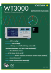
External dimensions
Approximately 426 mm (W) × 177 mm (H) × 400 mm
(D) (excluding protrusions)
Weight
Approximately 15 kg (main unit with 6 input elements
and options installed)
*1 Emission, immunity and safety standards apply to products having the CE Mark. For all other products, please
contact your nearest YOKOGAWA representative as listed on the back cover of this manual.
*2 Overvoltage Categories define transient overvoltage levels, including impulse withstand voltage levels. Overvoltage Category II: Applies to equipment supplied with electricity from fixed installations like a distribution
board.
*3 Pollution Degree: Applies to closed atmospheres (with no , or only dry, non-conductive pollution). Pollution
Degree 2: Applies to normal indoor atmospheres (with only non-conductive pollution).
*4 Annex A (normative): Immunity test requirements for equipment intended for use in industrial locations.
Model and Suffix Codes
The numbers in the "Descrip-tion"
column have the following meanings.
50: 50 A input element
5: 5 A input element
Blank: No element
Elements are inserted in the or-der
shown starting on the left side on the
back.
Communication
functions
Power cord
Option
specifications
쐽Clamp on Probe
Specification
20 Hz to 20 kHz, 600Apk ( 400 Arms)
30 Hz to 5 kHz, 1400Apk (1000Arms)
Model
96001*
751552
Order Q’ty
1
1
* For detailed information, see Power Meter Accessory Catalog Bulletin 7515-52E
* 96001 is a Yokogawa M&C product.
쐽Accessory (sold separately)
Product
Test read set
Small alligator-clip
Large alligator-clip
Safety terminal adapter
Safety terminal adapter
Conversion adapter
Model
/parts number
758917
758922
758929
758923
758931
7515121
Conversion adapter
Conversion adapter
Fork terminal adapter
External sensor cable
printer roll paper
758924
3669221
7589211
B9284LK
B9316FX
Description
Order Q’ty
A set of 0.8m long, red and black test leads
Rated at 300V and used in a pair
Rated at 1000V and used in a pair
(spring-hold type) Two adapters to a set.
(screw-fastened type) Two adapters to a set.
1.5 mm hex Wrench is attached
Safety-terminal-binding-post adapter
BNC-banana-jack(female) adapter
BNC-banana-jack(male) adapter
Banana-fork adapter
Current sensor input connector. Length 0.5m
Thermal paper, 10 meters (1roll)
1
1
1
1
1
1
1
1
1
1
1
Due to the nature of this product, it is possible to touch its metal parts. Therefore, there is a risk of electric shock, so
the product must be used with caution.
1: Use these products with low-voltage circuits (42V or less).
쐽Application Software
Product
WTViewer
Model
760122
Description
Data acquisition software
Order Q’ty
1
쐽Current Sensor Unit and Current Transducer
Model Code
751521
751523
Supply voltage
Suffix Code
-10
-20
-30
-1
-3
-7
Power cord
-D
-F
-R
-J
-H
Description
Single phase
3 phase U, V
3 phase U, W
3 phase U, V, W
100V AC (50/60Hz)
115V AC (50/60Hz)
230V AC (50/60Hz)
UL/CSA standard
VDE standard
SAA standard
BS standard
GB Standard
Accuracy assurance and calibration are possible when the Current Sensor Unit (Model 751521, 751523) is combined
with WT series instruments or the PZ4000.
Model Code
751574
Description
Max. 600 Apeak DC-CT
Assured accuracy and calibration are not possible when the Current Transducer (Model 751574) is combined with WT series instruments or the PZ4000. Also
please be aware that measurement errors can occur depending on the conductor and wiring.
Suffix codes
-01
-02
-03
-04
-05
-06
-10
-11
-12
-13
-14
-15
-20
-21
-22
-23
-24
-30
-31
-32
-33
-40
-41
-42
-50
-51
-60
-C1
-C2
-D
-F
-R
-Q
-H
/B5
/C7
/C10
/DA
/MTR
Description
WT1600 digital power meter main unit
Element Number
1
2
3
4
5
50
50
50
50
50
50
50
50
50
50
50
50
50
50
50
50
50
50
50
50
5
5
50
5
50
50
5
50
50
50
5
50
50
50
50
5
50
50
50
50
5
5
5
5
50
5
5
50
50
5
5
50
50
50
5
5
50
50
50
5
5
5
5
5
5
50
5
5
5
50
50
5
5
5
50
50
5
5
5
5
5
5
5
5
50
5
5
5
5
50
5
5
5
5
5
5
5
5
5
5
5
5
5
5
5
GP-IB
Serial (RS-232)
UL/CSA Standard
VDE Standard
SAA Standard
BS Standard
GB Standard
Internal printer
SCSI interface
Ethernet, HDD, SCSI
30-channel DA output
Motor evaluation function
6
50
Accessories for 751574
Product
Output connector
Burden resistor
Pare No.
B8200JQ
B8200JR
Speciffications
D-Sub 9 pin, with screws
10 Ω 4 pcs.
Minimum Purchase Quantity
1
1
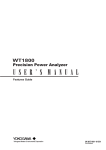
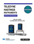
Exterior (WT1600)
Unit: mm
50
50
50
50
13
426
23
13
377
28
17
50
5
177
Element types and quantities
Order Q’ty
1
1
20
Model
760101
Description
For EIA
For JIS
Model
751535-E4
751535-J4
Product
Rack mounting kit
Rack mounting kit
Safety standard*1
The TCP/IP software used in this product and the documentation for that TCP/IP software are based in part on BSD Networking Software, Release 1 licensed from The Regents of the University of California.
* The WT1600 unit cannot be purchased without any elements. Select an element type (5 A or 50 A) and quantity.
Note: In order to add elements and options after the WT1600 has been delivered, the WT1600 must be
modified at the factory. Be aware of this in making your product selections. For further details, see
Yokogawa's home page or contact our sales office.
4/4
쐽Standard accessories
Power cord, Spare power fuse, Rubber feet, current input protective cover, User's manual, communication
interface user's manual, printer roll paper(provided only with /B5), 36-pin connector (provided only with /DA)
The B9284LK external sensor cable (blue) and the safety terminal adapter are sold separately.
OKOGAWA ELECTRIC CORPORATION
Test and Measurement Business Div./Phone: (81)-55-243-0313, Fax: (81)-55-243-0396
E-mail: [email protected]
YOKOGAWA CORPORATION OF AMERICA Phone: (1)-770-253-7000, Fax: (1)-770-251-2088
YOKOGAWA EUROPE B.V.
Phone: (31)-33-4641806, Fax: (31)-33-4641807
YOKOGAWA ENGINEERING ASIA PTE. LTD Phone: (65)-62419933, Fax: (65)-62412606
Subject to change without notice.
[Ed : 04/b] Copyright ©2001
Printed in Japan, 404(KP)
MS-13E