1
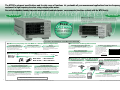
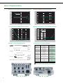
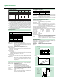
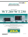
ENERGY SAVING TOOLS
Digital Sampling Power Meters
with Superior Cost Performance
Digital Power Meters
WT210/WT230
● Basic power accuracy: 0.1% ● DC measurement, 0.5 Hz to 100 kHz power frequency range
● Compact design (half-rack size)
● 5 mA range for very low current measurements (model WT210 only)
● Line filter function ● High-speed data update (as fast as 10 readings per second)
● Harmonic measurement function available
● User calibration capability
www.yokogawa.com/tm/
... and subscribe to “Newswave,”
our free e-mail newsletter
Bulletin 7604-00E
The WT230’s advanced specifications and its wide range of functions let you handle all your measurement applications from low-frequency
equipment to high frequency inverters using a single power meter.
One unit also handles standby low-power measurements and rated-power measurements (functions available with the WT210 only).
WT230
WT210
● Wide range of 5 mA to 20 A
The built-in 5 mA range lets you measure currents as low as 25 µA. This makes it possible to measure very
low currents on such things as intermittent control equipment. The wide current range (5 mA to 20 A) means a
single power meter can be used for applications such as Energy Star® measuremnts, to measure everything
from standby-power to rated-power.
Fr ee NEW
Soft ware
WTViewer for the WT210/WT230
Easily Acquire and Manage Power
Measurement Data from Your PC
See 8 pages or
Bulletin 7604- 32E for details.
Functions and Features of the WT210 and WT230
NEW
Low-frequency Equipment
Low-frequency measurements starting at 0.5 Hz
NEW
Low-frequency measurements starting at 0.5
Hz can be used with evaluations of
cycloconverter and when a motor are started.
Commercial Power Supplies
0.1%
Power accuracy is even better than in former WT
series.
NEW
● Powerful Tools for Energy Measurement
Inverters
Extended Energy Measurement Applications
100 kHz power frequency range
Maximum integration time: 10,000 hours 3
Now you can obtain more precise
measurements on high-frequency equipment
such as inverters.
Average active power display3
Time can be set between 1 second and 10,000 hours (416 days) in 1second increments.
Battery equipment applications
Integrating power measurement by polarity
● Accuracy Is Assured between 1% and 130%
1: Maximum display is 140% of the rated input.
2: Conditions apply to accuracy from 110% to 130%.
1% input
130% input
12
Intermittent Control Equipment Applications
Power and current values can be integrated separately for positive and
negative polarities. Integrated values are shown with the decimal point
moving according to the integrated value.
The power of intermittent control
equipment changes significantly
over time. The average active power
in intermittent operations can be
displayed, which is highly effective
for consumed-power
measurements.
Average active power (W) =
Instantaneous power Average power
Power
● A Wide Frequency Range Lets You Work on a Variety of Different Applications
Integrated power (Wh)
Integrated elapsed time (Hours)
Time
26A
960 01
751552
With 960 01 ➞ Max. 400 Arms
With 751552 ➞ Max. 1000 Arms
● Capture a Variety of Signal Types
Surge current and maximum load state
MAX hold function for voltage, current, and power 3
This function lets you keep, on the display, voltage and current peak
values, voltage and current rms values, and maximum values for active
power, apparent power, and reactive power.
Constantly changing signals
NEW Quick response with display updating as fast as every 0.1 second
With measurement intervals as short as 0.1 second, you can capture
transient phenomena with a fine level of detail. You can also reduce the
time per measurement for increased through put in production testing.
● Applications for a Variety of Add-on Options
Large-current Measurement Using Current Clamps
Online Power Meter Control and Recording
Power Supply Harmonic Measurements
External input for current sensor 4
GP-IB/serial (RS-232-C) interface
Calculate voltage, current, reactive power,
content ratio, and phase angle relative to
fundamental frequency for up to 50 orders. This
option is well-suited to power supply environment
evaluations. Measurement time is approximately
90% shorter than in former models.
Select either 50/100/200 mV or 2.5/5/10 V.
This option lets you control the power
A current clamp lets you measure currents
meter through a PC, or save data to a
without needing to disconnect the power supply
PC.
circuit wiring.
GP-IB/serial interface (RS-232-C)
4: Please select /EX1 (2.5/
Clamp
5/10 V) option when you
probe
External
use 960 01.
input
D/A output
Half-wave Rectification, Intermittent Control, Distortion Waves
Measurement of DC components
In addition to using DC inputs, you can obtain precise measurements of
signals containing DC components, such as intermittent signals and halfwave rectification signals.
NEW
Comparator output
Noisy Signals
Line filter function (fc = 500 Hz)
This function lets you measure fundamental wave rms values for inverter
output voltages.
Instead of taking notes, you can use the internal memory to store and recall
settings and field measurement data.
Recording to a Recorder
GO/NO-GO Evaluations on Testing Lines
D/A output
4-channel comparator function
This option lets you output a variety of measurement
data, such as voltage, current, and power measurements,
with ±5 V rating, for recording on a recorder. The recorder
can then be used to check changes in data over time.
A 4-channel relay contact output (normal-open and normal-close pair) lets
you do GO/NO-GO evaluations on production and testing lines.
Recorder
2
3
Information on the features and functions of Yokogawa's WT210, WT230, accessories, and related products is also available at our web site. http://www.yokogawa.com/tm/
3: Popular functions on the WT200 were incorporated into WT210 and WT230.
Basic Characteristics
Example of Frequency-power Accuracy Characteristics
Example of WT210 Current Accuracy
10
Indicated value tolerance (% of reading)
10
Tolerance (% of range)
WT230 15 V/1 A range
Spec and reference values
5
0
-5
-10
0.1
1
10
100
1000
10000
100000
8
6
4
2
0
-2
-4
-6
100 mA range: 60 Hz input
-8
-10
0.1
1
Current Input Surge Withstanding Ability
5
300
WT230 150 V range
WT230 500 mA range
Spec and reference values
4
5 mA-20 mA range
0.5 A-20 A range
250
Tolerance (% of range)
Surge current value (Arms)
100
Example of Influence of Common Mode Voltage
350
200
150
100
3
2
1
0
50
0
0.01
10
Input level relative to set range (% of range)
Frequency (Hz)
0.1
1
10
100
-1
0.1
1
Input current time width (seconds)
Example of D/A Output Response
100
1000
10000
100000
Frequency (Hz)
Comparison with Former Models
Voltage input terminal
External input terminal
Voltage and current
basic accuracy
WT200/WT130
Binding post
Plug-in terminal (safety terminal)
WT210/WT230
Plug-in terminal (safety terminal)
BNC
0.25% of rng
0.2% of rng
Power basic accuracy
0.3% of rng (WT200)
0.35% of rng (WT130)
Frequency range
Assured accuracy range
Display updating interval
V, A, W display digits
DC, 10 Hz to 20 kHz
10% to 130% of range rating
0.25 second (fixed)
4 digits (WT130)
5 digits (WT200)
DC, 0.5 Hz to 100 kHz
1% to 130% of range rating
0.1/0.25/0.5/1/2/5 seconds
Line filter function
Frequency filter function
Key lock
No
Yes (fc = 300 Hz)
No
Yes (fc = 500 Hz)
Yes (fc = 500 Hz)
Yes
Approximately 3 seconds
0.25/0.5/1/2/5 seconds
Harmonic measurement display
updating interval
Remote signals when
comparator is installed
display update time
10
Online data format
Waveform data communications output
0.2% of rng
5 digits
All six signals listed to the left are added.
EXT HOLD and EXT TRIG are added. EXT START,
EXT STOP, EXT RESET, and INTEG BUSY are not added.
Pin assign is changed.
ASCII
No
ASCII, binary
Yes (need /HRM)
Addressable mode B for
GP-IB communications
Yes
No
Display digits (factory default)
Online output data digits (factory default)
4 digits
4 digits
5 digits
5 digits
Functions Included with the WT200 (but Not Included with the WT130) and Included with the WT210/WT230
• MAX hold function • Moving decimal point display based on integrated power value
• 10,000-hour maximum integration time • Integration with few data omissions • Average active power display
WT 230
4
WT 210
Specifications
The latest product information is available at our web site http://www.yokogawa.com/tm/. Review the specifications to determine which model is right for you.
Input Specifications
Parameter
Current
Voltage
Floating input
Input type
Resistance voltage divider
Rated values (ranges)
Measuring instrument loss
(input resistance)
Maximum instantaneous allowed input
(1 cycle, 20 ms duration)
Maximum instantaneous allowed input
(1 second duration)
Maximum continuous allowed input
Maximum continuous common mode voltage
(with 50/60 Hz input)
CMRR
600 Vrms across input terminal and case
Shunt input system
5/10/20/50/100/200 mA (WT210 only)1
; 0.5/1/2/5/10/20 A (WT210/WT230)
External input (optional): 2.5/5/10 V or 50/100/200 mV
Direct input:
Approximately 500 mΩ + approximately 0.1 µH (5-200 mA; WT210)
Input resistance: Approximately 2 MΩ
Approximately 6 mΩ + 10 mΩ (max)2 + approximately 0.1 µH (0.5-20 A; WT210)
Input capacitance: Approximately 13 pF
Approximately 6 mΩ approximately 0.1 µH (0.5-20 A; WT230)
External input:
Approximately 100 kΩ (2.5/5/10 V), approximately 20 kΩ (50/100/200 mV)
Peak voltage of 2.8 kV or rms value of 2.0 kV (whichever is less) 0.5-20 A (WT210/WT230): Peak current of 450 A or rms value of 300 A (whichever is less)
5-200 mA (WT210): Peak current of 150 A or rms value of 100 A (whichever is less)
External input: Peak value of 10 times range or less
Peak voltage of 2.0 kV or rms value of 1.5 kV (whichever is less) 0.5-20 A (WT210/WT230): Peak current of 150 A or rms value of 40 A (whichever is less)
5-200 mA (WT210): Peak current of 30 A or rms value of 20 A (whichever is less)
External input: Peak value of 10 times range or less
Peak voltage of 1.5 kV or rms value of 1.0 kV (whichever is less) 0.5-20 A (WT210/WT230): Peak current of 100 A or rms value of 30 A (whichever is less)
5-200 mA (WT210): Peak current of 30 A or rms value of 20 A (whichever is less)
External input: Peak value of 5 times range or less
600 Vrms (with output connector protective cover), CAT II / 400 Vrms (without output connector protective cover) CAT II
Direct input:
15/30/60/150/300/600 V
50/60 Hz, -80 dB or higher (±0.01% of range or less) with voltage input terminals shorted and current input terminals open and external input terminals shorted
Reference value (up to 100 kHz): ±((Maximum range rating)/(Range rating) × 0.001 × f% of rng) or less (voltage range and 0.5-20 A current range and external
input range3)
±((Maximum range rating)/(Range rating) × 0.0002 × f% of rng) or less (WT210; 5-200 mA range)
Note: 0.01% or higher. f is in kHz. 3 Decuple the above-formula about the external input range.
Input terminal type
Plug-in terminal (safety terminal)
A/D converter
Simultaneous conversion of voltage and current inputs
Resolution: 16 bits
Maximum conversion speed: Approximately 20 µs (approximately 51 kHz)
Direct input: Large binding post
External input: BNC connector (insulation type)
Range switching
Ranges can be set manually, automatically, or through online controls.
Auto-range function
Range raising: When a measurement exceeds 130% of the rating, or when the peak value exceeds approximately 300% of the rating
Range lowering: When a measurement falls to 30% or less of the rating, and the peak value falls to approximately 300% or less of the rating for the low range
Measurement mode switching
Any of the following, selected manually or through online controls: RMS (true rms value measurements for both voltage and current), V MEAN (calibration of
average-value-rectified rms value for voltage; true rms value measurement for current), DC (simple averages for both voltage and current)
Note: Current direct input and external sensor input cannot both be used at the same time. When you operate current input terminals and external input terminals, please be careful.
Since these terminals are electrically connected inside the instrument.
1, Connect wires that match the size of the measurement current.
2, Factory setting
Measurement Functions
Parameter
Voltage/current
Active power
Digital sampling; sum of averages method
System
DC, and 0.5 Hz to 100 kHz
Frequency range
3 (with rated input) 300 (with minimum effective input)
Crest factor
DC:
±(0.2% or rdg + 0.2% of rng)*
DC:
±(0.3% or rdg + 0.2% of rng)*
0.5 Hz ≤ f < 45 Hz:
±(0.1% of rdg + 0.2% of rng)
0.5 Hz ≤ f < 45 Hz:
±(0.3% of rdg + 0.2% of rng)
Temperature: 23±5°C
45 Hz ≤ f ≤ 66 Hz:
±(0.1% of rdg + 0.1% of rng)
45 Hz ≤ f ≤ 66 Hz:
±(0.1% of rdg + 0.1% of rng)
Humidity: 30-75% RH
66 Hz < f ≤ 1 kHz:
±(0.1% of rdg + 0.2% of rng)
66 Hz < f ≤ 1 kHz:
±(0.2% of rdg + 0.2% of rng)
Input waveform: Sinewave
1 kHz < f ≤ 10 kHz:
±((0.07 × f)% of rdg + 0.3% of rng)
1 kHz < f ≤ 10 kHz:
±(0.1% of rdg + 0.3% of rng)
10 kHz < f ≤ 100 kHz:
±((0.5% of rdg + 0.5% of rng)
10 kHz < f ≤ 100 kHz:
±(0.5% of rdg + 0.5% of rng)
Accuracy (three months after calibration)
(Conditions)
±((0.067 × (f-1))% of rdg)
Power factor: cosϕ = 1
In-phase voltage: 0 V DC
±((0.09 × (f-10))% of rdg)
±((0.04 × (f-10))% of rdg)
Frequency filter: ON at 200 Hz or less
Scaling: OFF
Display digits: 5 digits
After CAL is executed
Note: In the accuracy calculation formula, f is in kHz.
* Add ±10 µA to the current DC accuracy.
* Add ±10 µA × voltage reading to the power DC accuracy.
For cosϕ = 0
Power factor effect
45 Hz ≤ f ≤ 66 Hz: ±0.2% of VA (VA is a reading value of apparent power)
Reference data (up to 100 kHz): ±((0.2 + 0.2 × f)% of VA)
Indicated value tolerance for 0 < cosϕ < 1
Add (tanϕ × (effect when cosϕ = 0)% of power reading to the above power accuracy.
Note: In the accuracy calculation formula, f is in kHz.
Note: ϕ is the phase angle between voltage and current.
Effective input range
1-130% of voltage/current range rating (for accuracy at 110-130%, add the reading tolerance × 0.5 to the above accuracy)
Accuracy (12 months after calibration)
Add the accuracy's reading tolerance (three months after calibration) × 0.5 to the accuracy three months after calibration.
Line filter function
A low-pass filter can be inserted in the input circuit for measurement. The cutoff frequency (fc) is 500 Hz.
Accuracy with line filter on
Voltage and current: Add 0.2% of rdg at 45-66 Hz. Add 0.5% of rdg below 45 Hz.
Temperature coefficient
±0.03% of range/°C at 5-18°C and 28-40°C.
Power: Add 0.3% of rdg at 45-66 Hz. Add 1% of rdg below 45 Hz.
Display updating intervals
0.1/0.25/0.5/1/2/5 seconds
Lead/lag detecting
Lead/lag is detected correctly when phase difference equal to or greater than ±5° with both voltage and current inputs as sine waves equal to or greater than
50% of rated range-value, and the frequency is between 20 Hz to 2 kHz.
Measurement lower limit frequency
Data updating rate
0.1 second
0.25 second
0.5 second
1 second
2 seconds
5 seconds
Measurement lower limit frequency
25 Hz
10 Hz
5 Hz
2.5 Hz
1.5 Hz
0.5 Hz
rng: Range rdg: Reading
Frequency Measurements
Communication Functions (Optional for the WT210)
Measurement inputs: V1, V2, V3, A1, A2, or A3 (select one)
Measurement system: Reciprocal system
Measurement frequency ranges
100 ms: 25 Hz ≤ f ≤ 100 kHz
250 ms: 10 Hz ≤ f ≤ 100 kHz
500 ms: 5 Hz ≤ f ≤ 100 kHz
1 sec: 2.5 Hz ≤ f ≤ 100 kHz
2.5 sec: 1.5 Hz ≤ f ≤ 50 kHz
5 sec: 0.5 Hz ≤ f ≤ 20 kHz
Accuracy:
±(0.06% of rdg)
Conditions:
Input equal to at least 30% of voltage/current rated range.
Frequency filter function ON at 200 Hz and below.
Frequency filter cutoff frequency: 500 Hz
GP-IB or serial interface (RS-232-C) (select one)
GP-IB
Electrical and mechanical specifications:
Conform to IEEE Standard 488-1978 (JIS C1901-1987).
Functional specifications:
SH1, AH1, T5, L4, SR1, RL1, PR0, DC1, DT1, C0
Protocol:
Conforms to IEEE Standard 488.2-1992.
Code used:
ISO (ASCII) code
Addresses:
0-30 talker/listener addresses can be set.
Serial interface (RS-232-C)
Transmission mode: Asynchronous
Baud rates:
1200, 2400, 4800, 9600 bps
5
Specifications
Calculation Functions
Internal Memory Functions
Single- Three-phase 3-wire Three-phase 3-wire
phase 3- (2 voltages,
(3 voltages,
wire
2 currents)
3 currents)
Voltage ∑V
(V1 + V3)/2
(V1 + V2 + V3)/3
Current ∑A
(A1 + A3)/2
(A1 + A2 + A3)/3
Active power ∑W
Reactive
power
var, ∑var
Apparent
power
VA, ∑VA
Power
factor PF,
∑PF
Phase
angle deg,
∑deg
W1 + W3
Threephase 4wire
W1 + W2 + W3
vari = (VA2 - W2) var1 + var3
var1 + var2 + var3
VAi = Vi × Ai
VA1 + VA3
Pfi = Wi/VAi
∑W/∑VA
degi =
cos-1 (Wi/VAi)
cos-1 (∑W/∑VA)
3
2
(VA1 + VA3)
3
3
(VA1 + VA2 + VA3) VA1 + VA2 + VA3
Notes
1. This equipment's apparent power (VA), reactive power (var), power factor (PF),
and phase angle (deg) are calculated from voltage, current, and active power.
(Therefore, if the input contains a distorted wave, the values may not match those
of other measuring instruments based on different measurement principles.)
2. If either voltage or current falls to 0.5% of the range rating or less, then the apparent
power (VA) and reactive power (var) are displayed as zero, and errors are displayed
for power factor (PF) and phase angle (deg).
3. The sign of the var of each phase is displayed with +(positive). In the ∑var
calculation, the var value for each phase is calculated with a negative sign if the
current input leads the voltage input, and with a positive sign if the current input
lags the voltage input. Then the value of ∑ var may be displayed with –(negative).
4. Apparent power (VA) and reactive power (var) cannot be calculated and displayed
at the harmonics measurement mode.
Display Functions
Display unit:
Display areas:
7-segment LED (light-emitting diode)
3
Display area
Displayed information
A
V, A, W, VA, var (for each element), integration elapsed time
B
V, A, W, PF, deg (for each element, percentage (content percentage, THD)
C
V, A, W, V/AHz, Vpk, Apk, ±Wh, ±Ah (for each element), MATH
Measurement parameters Maximum display
V, A, W, VA, var
Display resolution
99999
0.001%
PF
±1.0000
0.01%
deg
±180.0
0.1*
±Wh, ±Ah
999999
0.0001%
VHz, AHz
99999
Input frequency/20,000
Display digits: 4 or 5 digits (selectable by user).
Factory default setting is 5 digits.
Units:
m, k, M, V, A, W, VA, var, Hz, h±, deg, %
Display updating intervals: 0.1/0.25/0.5/1/2/5 seconds
Response time:
Maximum 2 times the display updating interval (time required
for display value to enter accuracy range of final value with line
filter off, when range rating abruptly changes from 0% to 100%,
and from 100% to 0%)
Maximum display:
140% of voltage/current range rating
Minimum display:
About Vrms, Arms, and Ah, 0.5% of range rating.
Less than 0.5% is zero suppression.
Display scaling function
Effective digits: Selected automatically according to the digits in the voltage and
current ranges.
Setting range:
0.001 to 9999
Averaging function
There are two averaging methods (selectable by user):
Exponential average
Moving average
In cases where response can be set and exponential average is used, the attenuation
constant can be selected. In cases where a moving average is used, the number of
averages N can be selected from 8, 16, 32, and 64.
Auto-range monitor
An LED turns on when the input value is outside the range set for the auto-range.
MAX hold function
This function can be used to hold V, A, W, VA, var, Vpk, and Apk at maximum values.
MATH functions
System:
When a function key on DISPLAY C is pressed to select the
MATH functions, it is possible to perform efficiency (WT230 only)
and input crest factor measurements, as well as arithmetic
calculations on DISPLAY A and B measurements. In addition, it
is possible to display average active power for time-converted
integrated power.
Measurement data
Stored data
Normal measurement Harmonic measurement
WT210 (760401)
Data for 600 samples
Data for 30 samples
WT230 (760502)
Data for 300 samples
Data for 30 samples
WT230 (760503)
Data for 200 samples
Data for 30 samples
Store interval:
Display updating interval and 1 second to 99 hours, 59 minutes,
and 59 seconds
Recall interval: Display updating interval and 1 second to 99 hours, 59 minutes,
and 59 seconds
(Both can be set in 1-second increments.)
Panel setting information: Four different patterns of panel setting information can be written/
read.
Harmonic Measurement Function (optional)
System:
PLL synchronization
Measurement frequency range:
Fundamental frequency in range of 40-440 Hz
Maximum display:
99999
Display digits:
4 or 5 digits (selectable by user).
Factory default setting is 5 digits.
Measurement parameters: V, A, W, deg (WT210), V1, V2, V3, A1, A2, A3, W1, W2,
W3, deg1, deg2, deg3 (WT230), individual harmonic levels, rms
voltage, rms current, active power, fundamental frequency PF,
harmonic distortion rate, individual harmonic content
Measurement element: These parameters can only be measured simultaneously for
a single specified input element.
Sampling speed, window width, and analysis orders
The values for these parameters vary according to the input fundamental frequency
as shown below.
Fundamental frequency
Sampling speed
Window width
Analysis orders
40 ≤ f < 70 Hz
f × 512 Hz
2 periods of f
50
70 ≤ f < 130 Hz
f × 256 Hz
4 periods of f
50
130 ≤ f < 250 Hz
f × 128 Hz
8 periods of f
50
250 ≤ f ≤ 440 Hz
f × 64 Hz
16 periods of f
30
FFT data length:
1024
FFT processed word length: 32 bits
Window function:
Rectangular
Display updating interval:
0.25/0.5/1/2/5 seconds Updating is slower during online output
according to the communication speed and the number of
parameters transferred.
Accuracy:
Add ±0.2% of range to normal measurement accuracy.
Note: For nth-order component input, add ((nth order reading)
× (10/(m+1))%) to the n+mth order and n-mth order.
D/A Output (optional)
Output voltage:
±5 V FS (maximum approximately ±7.5 V) for each rated value
Number of outputs: 12 parameters with /DA12 option; 4 parameters with /DA4 option
Output data selection: Can be set separately for each channel.
Accuracy:
±(equipment accuracy + 0.2% of FS)
D/A converter:
12-bit resolution
Response time:
Maximum 2 times the display updating interval
Updating interval:
Same as the equipment's display updating interval
Temperature coefficient: ±0.05%˚C of FS
Output type
Frequency
D/A output
7.5V
5.0V
2.5V
0.5V
0 0.5Hz 1Hz
10Hz
100Hz
1kHz
10kHz 100kHz Display value
Integration
D/A output
7.0V
For input equal to 140% of rating
5.0V
Integration Functions
Display resolution:
Maximum display:
Modes:
Timer:
Count over flow:
Accuracy:
Timer accuracy:
Remote control:
The minimum display resolution changes together with the
integrated value.
-99999 to 999999 MWh/MAh
Standard integration mode (timer mode), continuous integration
mode (repeat mode), manual integration mode
Automatic integration start/stop based on timer setting.
Setting range: 000 h:00 min:00 sec to 10000 h:00 min:00 sec
(If the time is set to zero, manual mode is automatically set.)
When the integrated value exceeds 999999 MWh/MAh or falls
to at least -99999 MWh/MAh, the elapsed time is saved and the
operation is stopped.
±(display accuracy + 0.1% of rdg)
±0.02%
Starting, stopping, and resetting can be controlled through
external contact signals. This function is only available when
option /DA4, /DA12 or /CMP is installed.
For rated input
0
t0
t0: Rated setting time
Other parameters
D/A output
Display
140%
100%
0%
-100%
-140%
Output
7.0V
5.0V
0V
-5.0V
-7.0V
Note: For PF and
deg, there is no
output between ±5
and ±7 V. When an
error occurs,
approximately 7.5 V
are output.
7.5V
7.0V
5.0V
-140% -100%
Display value
0V
100% 140%
-5.0V
-7.0V
-7.5V
6
Integration time
■ Model Numbers and Suffix Codes
External Input (Optional)
Select either /EX1 or /EX2 for the voltage output-type current sensor.
/EX1:
2.5/5/10 V
/EX2:
50/100/200 mV
Specifications:
See the section on input specifications.
Suffix code
Model number
Description
760401
WT210 single-input element model
Power cord -D
Comparator Output (Optional)
Output method:
Normal-open and normal-close relay contact output (pair)
Number of output parameters and settings:
Four parameters; can be set separately on each output channel.
Contact capacitance: 24 V/0.5 A
D/A output (4-channel): See section on D/A output (optional)
UL/CSA standard
-F
VDE standard
-R
AS standard
-Q
BS standard
Options
External Control Signal (with D/A or /CMP Option Only)
External control signals:EXT-HOLD, EXT-TRIG, EXT-START, EXT-STOP, EXT-RESET,
INTEG-BUSY
Input:
TTL level negative pulse
Select one
/C1
GP-IB communication interface
/C2
Serial (RS-232-C) communication interface
Select one
/EX1
External input 2.5/5/10 V
/EX2
External input 50/100/200 mV
/HRM
Harmonic measurement function
/DA4
Select one
4-channel DA output
/CMP
Comparator and D/A, 4 channels each
Note: The WT210 communication interface cannot be changed or modified after delivery.
General Specifications
Warmup time:
Approximately 30 minutes
Operating temperature and humidity ranges: 5-40˚C, 20-80% RH (no condensation)
Storage temperature: -25-60˚C (no condensation)
Maximum operating elevation: 2000 meters
Insulating resistance: 50 MΩ or higher at 500 V DC across all of the following areas:
Voltage input terminals (ganged) and case
Current input terminals (ganged) and case
Voltage input terminals (ganged) and current input terminals
(ganged)
Voltage input terminals (ganged) of each element
Current input terminals (ganged) of each element
Voltage input terminals (ganged) and power plug
Current input terminals (ganged) and power plug
Case and power plug
Insulating withstand voltage:
3700 V for one minute at 50/60 Hz across all of the following
areas:
Voltage input terminals (ganged) and case
Current input terminals (ganged) and case
Voltage input terminals (ganged) and current input terminals
(ganged)
Voltage input terminals (ganged) of each element
Current input terminals (ganged) of each element
Voltage input terminals (ganged) and power plug
Current input terminals (ganged) and power plug
1500 V for one minute at 50/60 Hz across case and power plug
Power supply:
Free power supply (100-240 V), 50/60 Hz frequency
Consumed power: Max 35 VA for WT210, max 55 VA for WT230
External dimensions for WT210:
Approximately 213 × 88 × 379 mm (WHD) (excluding projections)
External dimensions for WT230:
Approximately 213 × 132 × 379 mm (WHD) (excluding
projections)
Weight:
Approximately 3 kg for WT210, approximately 5 kg for WT230
Safety standard
Complying standard EN61010-1
Overvoltage category (Installation category) II
Pollution degree 2
Emission
Complying standard EN61326 Class A
EN61000-3-2
EN61000-3-3
AS/NZS 2064 Class A
Immunity
Complying standard EN61326 Annex A
■ Exterior View
Unit : mm
73
359
356
23
19
179
88
250
213
Suffix code
Model number
Description
760502
WT230 2-input element model
760503
WT230 3-input element model
Interface -C1
Power cord
Select one
GP-IB communication interface
-C2
Serial (RS-232-C) communication interface
-D
UL/CSA standard
-F
VDE standard
-R
AS standard
-Q
Options
BS standard
/EX1
External input 2.5/5/10 V
/EX2
External input 50/100/200 mV
/HRM
Select one
Harmonic measurement function
/DA12
12-channel DA output
/CMP
Comparator and D/A, 4 channels each
Select one
■ Standard Accessories
Power cord, Power fuse, Current input protective cover, Rubber feet for the hind feet,
24-pin connector (provided only on options/DA4, /DA12, and /CMP), User’s manual
■ Wiring Types and Model Numbers
Model
760401
760502
760503
Single-phase 2-wire
✓
✓
✓
Single-phase 3-wire
–
✓
✓
Three-phase 3-wire (2 voltages, 2 currents)
–
✓
✓
Three-phase 3-wire (3 voltages, 3 currents)
–
–
✓
Three-phase 4-wire
–
–
✓
Wiring
■ Rack mounts
Product
Model or part number
Rack mounting kit
751533-E2
For WT210 EIA standalone installation
1
Rack mounting kit
751533-J2
For WT210 JIS standalone installation
1
Rack mounting kit
751534-E2
For WT210 EIA connected installation
1
Rack mounting kit
751534-J2
For WT210 JIS connected installation
1
Rack mounting kit
751533-E3
For WT230 EIA standalone installation
1
Rack mounting kit
751533-J3
For WT230 JIS standalone installation
1
Rack mounting kit
751534-E3
For WT230 EIA connected installation
1
Rack mounting kit
751534-J3
For WT230 JIS connected installation
1
Specification
Order quantity
Ask Yokogawa for information on rack mounts in which WT210 and WT230 are combined.
WT210
23
213
327
34
28.5
■ Accessories (sold separately)
132
Model number
21
13
Description
B9317WD
1.5 mm hex wrench
For fastening cable on 758931
B9284LK
External sensor cable
For external input; 50 cm
WT230
7
Related Products
758917
758922
758929
758923
758931
B9284LK
Measurement leads
Small alligator adapters
Large alligator adapters
Safety terminal adapter set
Safety terminal adapter set
External sensor cable
Two leads in a set. Use 758917 in
combination with 758922 or 758929.
Total length: 75 cm
Rating: 1000 V, 32 A
For connection to measurement leads
(758917). Two in a set.
Rating: 300 V
For connection to measurement leads
(758917). Two in a set.
Rating: 1000 V
(spring-hold type) Two adapters in a
set.
Screw-fastened adapters. Two
adapters in a set. 1.5 mm Allen
wrench included for tightening.
For the external input of the WT210
and WT 230.
Length: 50 cm
■ For current measurements with wires connected
■ For high-current measurements up to 1000 Arms
■ For high precision (0.05% + 40 µA)
960 01 Clamp on Probe
751552 Clamp on Probe
751574 Current Transducer
758917
366921
Conversion adapter1
Measurement leads
758924
758921
Fork Terminal Adapter
Conversion adapter
● Measurement frequency range: 20 Hz to 20 kHz
● Basic accuracy: 1.0% of reading + 0.2 mA (40 Hz to 1 kHz)
● Maximum allowed input: AC 400 Arms
● Output: 10 mV/A
● Measurement frequency range: 30 Hz to 5 kHz
● Basic accuracy: 0.3% of reading
● Maximum allowed input: AC 1000 Arms, max 1400 Apk (AC)
● Current output type: 1 mA/A
● Wide dynamic range: 0-600 A (DC)/600 A peak (AC)
● Wide measurement frequency range: DC and up to 100 kHz (-3 dB)
● High-precision fundamental accuracy: ±(0.05% of reading + 40 µA)
● ±15 V DC power supply, connector, and load resistor required.
A separately sold adapter (366921 or 758924) is required for connection
to WT210/WT230. This is a Yokogawa M&C Product. For detailed
information, see http://www.yokogawa.com/MCC/clamp.htm#96001
1 Use with low-voltage circuits (42 V or less).
A separately sold fork terminal adapter set (758921), measurement
leads (758917), etc. are required for connection to WT210/WT230. For
detailed information, see Power Meter Accessory Catalog Bulletin 751552E.
For detailed information, see Power Meter Accessory Catalog Bulletin
7515-52E.
Due to the nature of this product, it is possible to touch its metal parts. Therefore, there is a risk of electric shock, so the product must be used with caution.
Free Application Software
WTViewer for the WT210 and WT230
DAQLOGGER & GateWT
GateWT is a software package that can collect data measured by digital power meter WT
series including WT210 and WT230 through a GP-IB or serial (RS-232) Communication
interface. See Bulletin 04L00L00-00E for details.
LabVIEW* Driver Software (Free)
Download this software program from our web
site.
Easily Acquire and Manage Power Measurement Data form Your PC
WTViewer for the WT210/WT230 is a software application that allows you to load numeric
and waveform data measured with the WT210 or WT 230 Digital Power Meter to a PC via
GP-IB or serial (RS-232-C) communications.
Visit our web site to register your product and download this software
program.
http://www.yokogawa.com/tm/WT210/
* LabVIEW is a registered trademark of National
Instruments Corporation.
See our web site or the software catalog (Bulletin 7604-32E) for detailed specifications.
Information on the features and functions of Yokogawa’s WT series & PZ, accessories, and related products is also available at our homepage. http://www.yokogawa.com/tm/
Protecting the global environment
Yokogawa's products are developed and produced in facilities that have received
ISO14001 approval.
CAUTION
YOKOGAWA ELECTRIC CORPORATION
Test and Measurement Business Div./Phone: (81)-55-243-0313, Fax: (81)-55-243-0396
E-mail: [email protected]
YOKOGAWA CORPORATION OF AMERICA Phone: (1)-770-253-7000, Fax: (1)-770-251-2088
YOKOGAWA EUROPE B.V.
Phone: (31)-33-4641806, Fax: (31)-33-4641807
YOKOGAWA ENGINEERING ASIA PTE. LTD Phone: (65)-62419933, Fax: (65)-62412606
Read the user's manual carefully for correct and safe use of the
instrument.
Subject to change without notice.
[Ed : 02/b] Copyright ©2002
Printed in Japan, 307(YG)
MS-12E