1
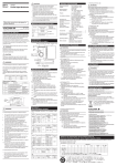
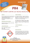
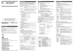
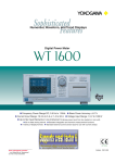
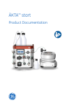
1. Description
This device is a current output type current sensor with a 1500:1(for CT1000) 1000:1(for CT200)
or 600:1(for CT60) current transformation ratio that performs transformation on the primary current.
After familiarizing yourself with the performance and functions of this device, you will be able to use
it in conjunction with measuring instruments from YOKOGAWA.
CT1000,CT200,CT60
AC/DC Current Sensor
User's
Manual
2. Configuration
The current sensor consists of the following parts.
Standard parts
1. Current sensor
2. User’s manual
Thank you for purchasing the AC/DC Current Sensor (Model CT1000,CT200,CT60). To ensure correct
use, please read this manual thoroughly before beginning operation.
After reading this manual, keep it in a safe place.
Accessories sold separately
Output connector
Load resistors
B8200JQ
B8200JR
3. Part Names
Attachment screw holes
(two M6)
Top
2nd Edition: January 2012 (YMI)
All Rights Reserved, Copyright © 2010, Yokogawa Meters & Instruments Corporation
Printed in Japan
Attachment screw holes
(four M5)
IM CT1000-01EN
2nd Edition
Secondary connector
Front
9
Safety Precautions
Pin assignment
5
Primary conductor
feed-through hole
Make sure to observe the following safety precautions when handling the current sensor. YOKOGAWA
assumes no liability for the customer’s failure to comply with these safety precautions. Before you
use the current sensor, read the measuring instrument’s manual to fully acquaint yourself with its
specifications and handling.
The following symbols are used on this instrument.
Warning: handle with care. Refer to the user’s manual or service manual. This symbol
appears on dangerous locations on the instrument which require special instructions for
proper handling or use. The same symbol appears in the corresponding place in the manual
to identify those instructions.
Risk of electric shock
1
6
Signal
Output return
[Do not connect]
[Do not connect]
0 V Power Supply Input
–15 V Power Supply Input
Secondary Signal Output
[Do not connect]
[Do not connect]
+15 V Power Supply Input
CT1000
Attachment screw holes
(two M5)
Attachment screw holes
(two M5)
Top
Attachment screw holes
(four M4)
Secondary connector
Make sure to observe the following safety precautions to prevent electric shock, personal
injury, or damage to the instrument.
1
Front
Conductor guide
CT200
(This directive is only valid in the EU.)
This product complies with the WEEE Directive (2002/96/EC) marking requirement.
This marking indicates that you must not discard this electrical/electronic product in
domestic household waste.
Product Category
With reference to the equipment types in the WEEE directive Annex 1, this product is
classified as a “Monitoring and Control instrumentation” product.
Do not dispose in domestic household waste. When disposing products in the EU,
contact your local Yokogawa Europe B. V. office.
4. Operating Procedure
CAUTION
Ensure that the current flowing to the conductor of the object to be measured is within the
measuring range. If the current exceeds the measuring range, the device may overheat and
get damaged.
1. Connect the secondary connector on the device to the current input terminal on the measuring
instrument, and connect to 0 V (common) and ±15 V on the power supply.
2. Set up the measuring instrument and power supply to match the specifications of the current
transducer. Carefully read the user’s manuals for your measuring instrument and power supply
to perform the correct procedure for making the connections.
Secondary connector
of the current sensor
6
이 기기는가정용 (B 급 ) 전자파 적합 기기입니다
The product is for home use (Class B) and meets the electromagnetic compatibility requirements.
KCC-REM-IMY-EEN314
Current Sensor
Yokogawa Meters & Instruments Corporation
Yokogawa Meters & Instruments Corporation
Denmark
Measuring instrument
Rb
Rb: Load resistor*
Current input
terminal
1
Power supply
4
5
9
0 V(common)
–15 V
+15 V
* Make sure that the total load resistance
including measuring instrument's internal
resistance and external load resistance (Rb)
is within the specification.
Figure 2. Connection Example
3. Insert the primary conductor into the primary conductor feed-through hole on the device.
Make sure that the direction of current flow matches the arrow on the device. Figure 3 is for the
examples in use with CT200 and CT60. The same idea is applied to CT1000 as well.
Correct
Conductor
Incorrect
Direction of current
Using an magnetic
-shielded conductor
Using two parallel
conductors
Primary current
Current flows in
both directions
Figure 3. Insertion of a Conductor
4. Check that power is being supplied to the device, and then apply the primary current.
5. Read the measured values. The following calculation is used to determine the current flowing
through the primary conductor.
Example: When the output current from the device's secondary connector (pin 6) is 100 mA.
CT1000: 100 mA x 1500 = 150 A.
CT200: 100 mA x 1000 = 100 A.
CT60: 100 mA x 600 = 60 A.
Note
•
•
Compliance with the Radio Waves Act (Republic of Korea)
This product complies with the Radio Waves Act (Republic of Korea).
Note the following when using the product in Republic of Korea.
CT60
Figure 1. Names of Parts and Pin Assignments
Calls attention to information that is important for proper operation of the instrument.
Directive 2002/96/EC
Pin assignment
Primary conductor feed-through hole
The following symbols are used in this manual.
Improper handling or use can lead to injury to the user or damage to the instrument.
This symbol appears on the instrument to indicate that the user must refer to the user’
s manual for special instructions. The same symbol appears in the corresponding
place in the user’s manual to identify those instructions. In the manual, the symbol is
used in conjunction with the word “WARNING” or “CAUTION.”
WARNING Calls attention to actions or conditions that could cause serious or fatal injury to the
user, and precautions that can be taken to prevent such occurrences.
CAUTION Calls attention to actions or conditions that could cause light injury to the user or
damage to the instrument or the user’s data, and precautions that can be taken to
prevent such occurrences.
5
6 9
WARNING
• Beware of electric shock.
• Do not perform measurement if the case is damaged.
• Do not operate the device with wet hands, in a rainy or humid environment, or if any
water droplets are visible on it.
• Condensation may appear if sudden changes in temperature occur. If this happens, let
the device acclimatize to the new temperatures for at least one hour, then refrain from
using the device until confirming that there is no condensation.
• Do not disassemble the device.
The device should be disassembled by qualified personnel only.
• Use the correct power supply.
Ensure that the source voltage matches the voltage of the power supply before turning
the power ON.
• Do not use uninsulated measurement conductors or cables.
Use conductors or cables with reinforced insulation.
• Make sure that the surface temperature of measurement conductors is within the
device's operating temperature range.
• Although it is well-insulated, do not touch the device or secondary output cable
while voltage is being applied to the primary conductor.
• Connect the secondary signal output before supplying power to the device.
• Do not disconnect the secondary output while power is being supplied to the device
to prevent electric shock or damage to the instrument.
• Do not apply primary current before supplying power to the device to prevent
electric shock or damage to the instrument.
• Do not input excessive current as malfunction or damage may result.
• Do not allow vibrations to disturb the device after it has been set in place as damage
may result.
Registration No:
Equipment Name:
Trade Name:
Manufacturer:
Country of Origin:
Pin No.
1
2
3
4
5
6
7
8
9
Conductor guide
Hot surface
Note
Signal allocation of secondary
connector
•
If the NORMAL OPERATION LED is off even when power is being supplied to the device, the
protection function may be activated. Immediately stop the primary current.
Only pass conductors through the primary conductor feed-through hole if the current that you
want to measure is flowing through the conductors and their current directions are the same.
Correct measurements cannot be taken if you pass conductors with magnetic shielding or
conductors whose current directions are opposite of each other through the feed-through hole.
Make sure the primary wiring and secondary wiring do not interfere with each other. The
secondary wiring may be affected by the primary wiring because it uses a very small current.
Make the secondary wiring as short as possible and maintain its distance from the primary
wiring, without allowing them to be parallel to each other. We recommend AWG24 or higher for
the secondary wiring material. Twisted-pair may be better than shielded cable for measurement
applications such as inverters.
IM CT1000-01EN 1/2
Maximum Allowable
Input Current [Arms]
10000
100000
100000
Figure 4. Derating of Primary Current by Frequency
CT1000
Unit: mm
2-Ф6.5 hole
109
104
90
4-Ф5.5 hole
Ф30
54
128
CT200, CT60
2-Ф5.5 hole
Ф30 Max
80
93
76
77.3
Ф26 Min
Unless otherwise specified, tolerances are ±3%
(however, tolerances are ± 0.3 mm when below 10 mm).
Figure 5. External Dimensions
6. Servicing
7. Warranty
If you experience a breakdown in the device due to faulty manufacturing or accidents during shipping,
contact your nearest YOKOGAWA dealer.
100
8. 产品中有毒有害物质或元素的名称及含量
This section is valid in China only.
10
部件名称
1
1
10
100
1000
Frequency [Hz]
10000
100000
100000
CT200
1000
Maximum Allowable
Input Current [Arms]
1000
Frequency [Hz]
If you encounter any problems during use, or if the device does not appear to be operating normally,
contact your nearest YOKOGAWA dealer.
CT1000
1000
100
9
Accuracy warranty period
Effect of Position of Conductor
Measurement Band
(-3dB)
Temperature Coefficient
In the 10 to 18°C, 28 to 50°C ranges: 0.01%/°C
Max. Allowable Continuous Input 1000 Apeak
200 Apeak
60 Apeak
Derating of Max. Allowable Input For the maximum allowable continuous current with respect to
frequency, see figure 4.
Instantaneous Max. Allowable
4500 Apeak
1000 Apeak
300 Apeak
Input
(0.1 sec. or less, reference value)
Maximum Rated Voltage
1000 Vrms CAT III
Load Resistance
2.5 to 5 Ω
0 to 30 Ω
0 to 20 Ω
Operating
Temperature
10 to 50°C
environment Humidity
20 to 80%RH (no condensation)
Altitude
2000 m or less
Storage
Temperature
-20 to 60°C
environment Humidity
20 to 80% RH (No condensation)
Altitude
3000 m or less
External Dimensions
Approx. 128(W) x
Approx. 93(W) x 77(H) x 38(D) mm
106(H) x 60(D) mm
(excluding the connector and conductor guide)
Diameter of Primary Current Hole φ30 mm
φ26 mm
Secondary Connector
D-Sub 9 pin
Weight
Approx. 0.8 kg.
Approx. 0.3 kg.
Power Supply Voltage
±(15 V ± 5%)
Maximum Rated Power
30 VA
11 VA
7 VA
Consumption
Current Consumption (at Power Approx. (150 mA +
Approx. (80 mA + output current)
Supply Voltage)
output current)
Recommended fastening torque
•Flat mounting
M5×4 steel screws
M4×4 steel screws
3.7 Nm
2.8 Nm
•Straight mounting
M6×2 steel screws
M5×2 steel screws
4.4 Nm
3.7 Nm
Safety standard
Compliant standards
EN61010-1
Emissions
Compliant standards
E
N61326-1 ClassB, EN55011 ClassB, Group1
C-tick EN55011 ClassB, Group1
Immunity
Compliant standards
EN61326-1 Table 2 (for industrial locations)
Accessories
User’s manual: 1 pc.
Opt. Accessories (Sold
•D-Sub 9 pin connector (plug, part number B8200JQ): 1 pc.
Separately)
•Load resistor (four 10-Ω resistors, part number B8200JR, accuracy
of resistance value ±0.1%, temp. coefficient 25 ppm/°C): 1 group.
Example: To apply a 2.5 Ω load resistance, connect the four 10 Ω
resistors in parallel.
10
38.8
Current Transformation Ratio
Direction of Current
Accuracy
1
30
Output Current
1
60
Current Rating
Model
CT1000
CT200
CT60
DC: 0 to 1000 A
DC: 0 to 200 A
DC: 0 to 60 A
AC: 1000 Apeak
AC: 200 Apeak
AC: 60 Apeak
Primary rated current Primary rated current Primary rated current
at 1000 A is 666.6 mA. at 200 A is 200.0 mA. at 60 A is 100.0 mA.
1500:1
1000:1
600:1
Per the arrow printed on the main unit.
DC: ±(0.05% of reading+30 μA)
50/60 Hz: ±(0.05% of reading+30 μA) sine wave
Standard Conditions
23±5°C
Common mode voltage:0 V
Conductor: φ25 mm; length,300 mm or more; straight
12 months
Add ±(0.01% of reading)
DC to 300 kHz
DC to 500 kHz
DC to 800 kHz
85
Item
20.3
5. Specifications
10
67
•
106
•
CT60
100
38
The device outputs current. Connect the device to a measuring instrument with current input.
To connect the device to a measuring instrument with voltage input, use an appropriate shunt
resistor to connect the device to the voltage input terminals.
Configure your setup so that the load resistance of the measuring instrument connected to the
secondary signal output is within the specification range.
Correct measurements may not be possible in places where there is an extremely strong
external magnetic field besides the magnetic fields produced by the primary current of the
object to be measured or where there is a strong electric field.
Maximum Allowable
Input Current [Arms]
•
100
有毒有害物质或元素 铅
汞
镉
六价铬 多溴联苯 多溴二苯醚
(Pb) (Hg) (Cd)(Cr(VI))(PBB) (PBDE)
框架(塑料) ○
○
○
○
○
○
○
○
○
○
○
框架(金属) ○
线路板
○
○
○
○
○
○
ASSY
○:表示该有毒有害物质在该部件所有均质材料中的含量均在 SJ/T
11363-2006 标准规定的限量要求以下。
×:表示该有毒有害物质至少在该部件的某一均质材料中的含量超
出 SJ/T 11363-2006 标准规定的限量要求。
9. 环保使用期限
10
This section is valid in China only.
表示该有毒有害物质在该产品中的含量均在 SJ/T 11363-2006 标准规定的限量要
求以下。
1
1
10
IM CT1000-01EN 2/2
100
1000
Frequency [Hz]
10000
100000
100000