1
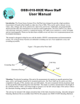
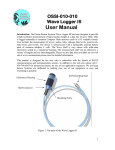
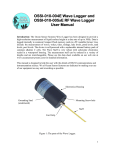
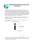
OSSI-010-022 Wave Gauge Blue User Manual Introduction: The Ocean Sensor Systems Wave Gauge Blue has been designed to provide a high-resolution measurement of liquid surface height at a data rate of up to 32Hz. Uses include the measurement of waves, wakes, tides, sinkage, lake levels, pond levels, tank levels and pool levels. The instrument is capable of collecting and storing data for more than a year on standard compact flash cards. It can collect data continuously or in a burst sampling mode; sampling for short periods and then going into low power sleep mode. The instrument is self-powered using 12 or 28 Alkaline C cells. The Wave Gauge Blue is very robust with solid-state electronics sealed in a waterproof housing. The type of pressure transducer used is an Absolute Transducer with the output zeroed at one atmospheric pressure. The gauge pressure is the total pressure, minus atmospheric pressure. So at sea level it reads zero. The instrument can be ordered in a variety of pressure ranges. Please see the data sheet available on our web site at www.oceansensorsystems.com for detailed information. This manual is designed to help the user with the details of serial communications and instrumentation science. We at Ocean Sensor Systems are dedicated to making your use of our equipment as easy and rewarding as possible. Mounting: The physical mounting of the unit at the measurement site requires no special protection. It must be mounted securely and below the lowest, expected water surface level. The Wave Gauge Blue may be used in any fluid compatible with Buna-n o-rings, Silicone o-ring grease, stainless steel, and ABS plastic. The output is a measurement of the pressure at the location of the sensor orifice, (a ½ inch dia. hole), located on one end of the Wave Gauge Blue. In mounting, do not cover over the orifice opening. The ABS housing must be mounted securely and must never be submerged more than 1.5 x the maximum rated pressure range. 0 to 1 Bar will have a maximum depth of 16 meters 0 to 3 Bars will have a maximum depth of 46 meters 0 to 10 Bars will have a maximum depth of 151 meters 1 Mounting can be to a vertical mooring cable, a bottom mounted base or a submerged piling. Mounting is accomplished by clamping to the ABS housing. Power Requirements: The Wave Gauge Blue comes supplied with a battery pack of 12 alkaline C cells connected in series. This provides a nominal 18 volt to the Wave Gauge Blue. The Interface Software provides a means to estimate the battery. Replacement alkaline battery packs are available from Ocean Sensor Systems. Alternately 12 individual, new, alkaline C cells may be configured as shown below and the power connector transferred from the old battery pack to the new pack. An optional extended case (Identified with the letter E at the end of the Wave Gauge Blue part number) is supplied with a battery pack of 28 alkaline C cells. There are two groups of 14 cells connected in series. Replacement alkaline battery packs are available from Ocean Sensor Systems. Alternately 28 individual, new, alkaline C cells may be configured as shown below and the power connector transferred from the old battery pack to the new pack. 2 Control Panel: The Wave Gauge is opened by unscrewing the top of the black plastic housing from the base in a counter clockwise direction. When opening the unit, be careful not to let the battery drop by holding the Wave Gauge in an upright position or on its side lying on a table. Inside the unit is a control panel. The control panel has a slot for the Compact flash card, a button to allow removal of the compact flash card, an LED indicator light, a battery connector and a connector for the Programming RS232 adapter cable. The Wave Gauge Blue is used by inserting a compact flash card (64MB to 64GB) in the slot with the card label down in relation to the control panel text. The card should slide easily into the unit with a slight resistance for the last 1/16”. The card when installed correctly will be straight and flush with the top surface of the control panel. Next, connect the battery with the unit by putting the unit connector and batter connector together. The connectors should be secured within the track on the side of the battery pack. If the status is OK the LED indicator light will flash on for 3 seconds. If the LED light blinks rapidly at about 3 times a second, the unit cannot identify the compact flash card. This is due to one of the following: The wrong type or size of compact flash card is inserted The compact flash card is not formatted The card was not installed correctly If the problem persists please contact Ocean Sensor Systems. 3 With a compact flash card inserted and the battery connected, the Wave Gauge will begin to collect and store data when the clock seconds reaches zero. Be sure the battery is inserted snug against the control panel before closing the housings together. After data collecting is completed follow these steps to disconnect the battery and/or retrieve the flash card correctly. Lift the battery and push the Close File Button on the Control Panel. The indicator light will then blink slowly at about 1Hz to indicate that all open files have been properly closed and it is safe to remove either the compact flash card or the battery connector. Failure to push the button will cause the data to be lost. Serial Communications: The Ocean Sensor Systems Wave Gauge Blue is an intelligent device and allows for data exchange and reconfiguration through serial communications to a computer. The communication may be made by either a Wireless Bluetooth or RS232 COM port. The Serial Port Adapter, supplied with the Wave Gauge Blue, connects to a DB9 connector on the computers. If your computer does not have a DB9 serial port connector you will need to use a USB to Serial adapter or the included wireless Bluetooth adapter. Once the Wave Gauge Blue is connected to the computer, it may be powered up by connecting the battery to the unit. Ocean Sensor Systems has a Graphical User Interface available to download free of charge from www.oceansensorsystems.com. The New Interface Software works on Windows based computers and allows configuration, and display of data. Details for the use of this program are given below. Alternately, a program like a HyperTerminal may be used set to 115.2Kbaud, Data Bits 8, Parity None, Stop Bits 1 and Flow Control None. See the Wave Gauge Blue specification for detailed information. 4 Software Interface: The Wave Gauge interface software is available from Ocean Sensor Systems and contains all of the features necessary to, configure, monitor and display raw and processed wave data or even upload small test files. It will run on most Windows based machines. The free Interface Program is available to downloaded and install on a PC from the Ocean Sensor Systems web site. There are several methods that the PC can link to the Wave Gauge Blue. An internal RS232 Port is provided which can be connected to the PC using the Serial interface cable. The port is located on the control panel and is labeled COM1 RS232. A wireless Bluetooth connection may also be used to connect the Interface Software to the Wave Gauge Blue. 1234 is the pairing code when the unit was shipped from Ocean Sensor Systems, Inc. (See appendix A). A third method is via an optional Shore Connector which can be included in the Wave Gauge Blue at time of purchase. 5 After the serial port is connected and the Wave Gauge Blue is power up, run the Interface software. Use the Serial Com Port Pull Down Menu to select the correct com port. After selecting the correct serial com port a connection to the Wave Gauge Blue will be attempted automatically. If successful the status indicator will display Connected with green letters and all of the Wave Gauge Blue’s configuration settings will be displayed. To change the Wave Gauge Blue’s configuration simply change a value on the display. The Wave Gauge Blue will be automatically updated to the new value. Just left click the mouse over any object for help! Operation: After unpacking the unit, check to see that there is a battery pack with a connector, a DB9 serial communication cable, a Wave Gauge Blue, a compact flash card and Bluetooth Adaptor. The Wave Gauge Blue will accept compact flash card sizes from 64MB to 64GB. The top of the Wave Gauge Blue housing (the part with the label) unscrews from the bottom. Do not screw them together too tightly or it will become difficult to reopen! If the flash card is not yet installed, insert the flash card with the label upside down facing you. The extra ridge on the card will be to the back as indicated on the panel. The battery may be plugged into the cable extending from the electronics. The LED will now signal the following 1. ON FOR 3 SECONDS = CARD INSERTED OK /COLLECTING DATA 2. CONTINUOUS 1 SEC. ON & 1 SEC. OFF = OK TO REMOVE CARD. STOPS AFTER CARD REMOVED 3. FAST BLINKING = CARD REMOVED BEFORE CLOSING FILE OR BAD CARD FORMAT. If the LED signals for 3 seconds the unit will begin to collect data normally. If the red LED flashes rapidly several times, the initialization has failed and the battery should be unplugged and reinserted. To view the data, push the small recessed button on the top of the electronics. The red LED will begin to blink at a one second interval to indicate that you may now remove the flash card. Failure to push the button will cause the data to be lost. Insert the flash card 6 into a PC based flash card reader (user supplied). The files may be imported into the Interface Software, Word Pad, Exel, Matlab or other text or analysis program. To assemble the unit for deployment, a light coating of silicon o-ring grease should be applied to the o-rings and sealing surfaces. The battery is set into the recess in the bottom half of the unit. The battery connector secured within the track on the side of the battery pack. The cover or top half of the Wave Gauge Blue may now be screwed all the way down over the bottom half. Do not screw the halves together too tightly as it will become difficult to separate them. Very important notes about the Wave Gauge Blue: Note 1: Remember to tell anyone using it that they MUST NOT GET ANY SALTWATER or SWEAT INSIDE THE UNIT AS THIS WILL CORRODE THE CIRCUITRY! It must be thoroughly dried before it's opened. Then lay the unit down on its side. Open the unit very carefully, if there is any water around the 0 Ring it will not fall into the unit and can be further dried. Hands must be totally dry when opening and handling the unit. Note 2: If enabled “The New file Interval In Days” will start a new file at 0000 hours with no sample data lost. Note 3: See the user manual for information on changing the Wave Gauge Blue’s configuration. Maintenance: The Ocean Sensor Systems Wave Gauge Blue requires minimal maintenance. Prolonged exposure may require wiping off any slime buildup from the case using only soap, water and a soft cloth. The o-ring should be periodically wiped with a thin film of silicone o-ring grease. The o-ring, o-ring groove and inside of the case must be kept free of particles and scratches that may prevent the o-ring from sealing. Replacement o-rings are Buna-N O-Ring AS568A Dash Number 233 and Buna-N ORing AS568A Dash Number 042. The only other maintenance is the periodic replacement of the batteries. Data Files: The Wave Gauge Blue stores the data in units of bars as ASCII format. See the Wave Gauge Blue Data Sheet for file format. After the system has been deployed and data collected, the pressure vessel may be opened up and the compact flash card removed and the data recovered. Data Analysis: Accurate estimation of the wave spectra from pressure data requires filtering the data to remove the attenuation of the wave pressure field with depth. The attenuation is a function of the wavelength, the depth of the water column and the deployed depth of the instrument. As a rule of thumb, estimates of the surface wave heights will be within +-5% if the ratio of the deployed depth over the wavelength is less than 0.3 to 0.5 (z/L <0.3 to 0.5). 7 At any given depth of deployment, there is a high frequency (short wave length) limit above which the waves are not measurable with pressure. This high frequency limit may be found using the following relationship: Fmax = frequency where subsurface /surface pressure = 0.025 * sample rate As an example, if we assume deepwater waves and if the data is collected at 2Hz, the ratio of the subsurface pressure over the surface pressure must be >= 0.025*2 or 0.05. If the deployment depth z = 5 meters then the highest frequency wave that can be measured is: (Psurface/Pinstrument= 1/ e –kz )<= 0.05 solving for k yields 15 or a 0.41 meter long wave. Below is a plot showing the maximum frequency measurable for a range of deployment depths when the sample rate is 2Hz. The maximum wave frequency limit for a range of deployment depths and a 2Hz sample rate. The raw pressure data from each burst is converted to a wave spectra by first dividing the burst into 50% overlapping segments of 128 points. Each segment is then detrended, windowed with a Hanning window and zero filled to 256 points. The power spectra is then calculated for each segment and averaged with the other power spectra from the burst. Frequencies above the cutoff frequency are set to zero. The significant wave height is estimated by 4 * Standard Deviation. The power spectra computed in the previous step must be corrected for depth attenuation. The pressure power spectrum is related to the wave power spectrum by 8 cosh k z h 2 S P ( ) S cosh kh where: z = depth of instrument h = depth of the water column k = 2*pi/L the wave number = the radial frequency 2 There are a number of programs available on the internet for making the spectral correction from the pressure time series. Example: Processing of wave data from pressure sensors by Dr. Urs Neumeier Below is a link to a research paper by Dr. Urs Neumeier on Processing of wave data from pressure sensors. He uses Matlab software with 3 routines for the post processing of the wave data. You can download the routines from his web site. http://neumeier.perso.ch/matlab/waves.html 9 Appendix A: Connecting with Bluetooth: If your computer does not have an internal Bluetooth Transceiver plug the BluePlug into a USB slot. Apply Power to the Wave Gauge Blue. On your computer open the Control Panel/Hardware and Sound/Devices and Printers and select “Add a device”. Select RN42-DBA1 and click on Next. Select Enter the device’s pairing code. 10 Enter the Wave Gauge Blue pairing code. 1234 is the pairing code for the unit when it was shipped from Ocean Sensor Systems, Inc. Select Next 11 To check the device connection, right click the RN42-DBA1 icon and select properties. The Services and Hardware windows will now show the serial com port number to use. 12 Changing the Bluetooth’s pairing code: First cycle the Wave Gauge Power by turning it off and back on. Follow the steps below using a program like a HyperTerminal. Set the Hyper Terminal properties to: 115.2Kbaud, Data Bits 8, Parity None, Stop Bits 1 and Flow Control None. 1. Connect to the Wave Gauge using the Serial Port Adapter. 2. To check the connection type “help”. The units command set should be displayed. 3. Bluetooth power must be on, “enter wb,1” “Bluetooth transceiver enabled” is returned. 4. Enter ”lb” this links the Serial directly to the Bluetooth Module 5. Type “$$$” then “CMD” should be returned. 6. Enter “d” to display the Bluetooth basic settings. PinCod=1234 is the pairing code. 7. Type “sp,” then enter the pairing code. 20 characters maximum. Don’t forget the comma between the sp and the pairing code. 8. Enter d again to check the new pairing code. 9. Now hit the Esc Key to exit link to the Bluetooth module routine. See http://www.rovingnetworks.com/ DOCUMENTATION LIBRARY Advanced User Manual for detailed information. References Module RN42 13