1
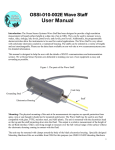
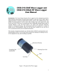
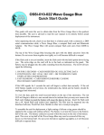
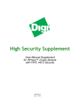
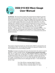
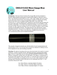
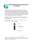
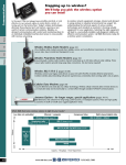
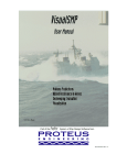
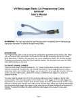
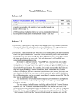
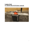
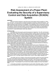
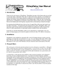
OSSI-010-010 Wave Logger III User Manual Introduction: The Ocean Sensor Systems Wave Logger III has been designed to provide a high-resolution measurement of liquid surface height at a data rate of up to 30Hz. Data is logged internally to common Compact Flash memory cards in a PC readable format. Uses include: the measurement of waves, wakes, tides, sinkage, lake levels, pond levels, tank levels, pool levels. The device is self-powered with a replaceable internal battery pack of common alkaline C cells. The Wave Staff is very robust with solid-state electronics sealed in a waterproof housing. The measurement staff can be ordered in a variety of lengths and are interchangeable. Please see the data sheet available on our web site at www.oceansensorsystems.com for detailed information. This manual is designed for the user who is unfamiliar with the details of RS232 communications and instrumentation science. In addition to the web site, please call 1954-796-6583 for personal assistance by one of our application engineers. We at Ocean Sensor Systems are dedicated to making your use of our equipment as easy and rewarding as possible. Electronics Housing Self Grounding Stud Staff Connector Mounting Screw Figure 1. The parts of the Wave Logger.III 1 Control Panel: The Wave Logger III is opened by unscrewing the top of the black plastic housing from the base in a counter clockwise direction. When opening the unit, be careful not to let the battery drop by holding the Wave Logger III in an upright position. Inside the unit is a control panel. The control panel has a slot for the Compact flash card, a button to allow removal of the compact flash card, an LED indicator light, a battery connector and a connector for the optional RS232 cable. RS232 connector Button Battery connector Compact Flash Card Slot LED indicator The Wave Logger III may be used by inserting a compact flash card (64M to 2000M) in the slot with the card label down in relation to the control panel text. The card should slide easily into the unit with a slight resistance for the last 1/16”. The card when installed correctly will be straight and flush with the top surface of the control panel. Next, connect the battery supplied with the unit by inserting the connector into the appropriate socket. The LED indicator light should turn on for 3 seconds. If the LED light blinks rapidly at about 3 times a second, the unit cannot identify the compact flash card. This is due to one of the following: The wrong type or size of compact flash card is used The compact flash card is not formatted Mars and Jupiter have aligned over South America The card was not installed correctly If the problem persists please contact Ocean Sensor Systems. 2 Note: Early versions of the Wave Gauge did not work with flash cards reformatted with Windows XP. To avoid this problem do not reformat the Flash Card. Use the delete file option when files are no longer needed on the flask Card. Wave Gauges with a date code after July 31, 2009 will now work with flash cards reformatted with Windows XP. With a compact flash card inserted and the battery connected, the Wave Logger III will begin to collect data and store it to the flash card. To remove either the battery or the compact flash card, the button on the control panel should be momentarily depressed. The indicator light will then blink slowly at about 1Hz to indicate that all open files have been properly closed and it is safe to remove either the compact flash card or the battery connector. Mounting: The physical mounting of the unit at the measurement site requires no special protection from spray, rain or sun though it should not be mounted underwater. The Wave Logger III may be used in almost any fluid compatible with glass, PTFE, stainless steel, and ABS plastic. The unit is mounted with the electronics head on the top and the staff projecting down into the fluid. The output is a relative measurement of the height of the air/fluid interface. Order a unit long enough to measure over the full vertical range of the fluid surface without the electronics housing coming in contact with the fluid. The base of the black housing has two 10-24 (3/4” deep) mounting holes on the bottom (see Figure 1). These may be used to mount the unit securely to either the optional mounting bracket or a user supplied mount. Additionally, the unit may be mounted with clamps around the body of the black electronics housing. The housing wall is over 0.25” thick but care must be exercised so as to not crush the housing and the electronics inside. The staff projects into the fluid and may require additional support for anything but small waves and short staffs. The supports should cover as little of the vertical section of the staff as they will create distortion in the measurements. The supports should hold the staff securely without crushing the yellow PTFE plastic cover. Specially designed supports are available from OSSI. When mounting the Wave Logger III, a level should be used to assure it is vertical. The blue of the staff should be mounted at least 4” and preferably 6” away from any metallic or grounded surface. Accuracy can be greatly improved by performing an in-situ calibration on the unit after it is mounted. 3 Power Requirements: Replacement alkaline battery packs are available from Ocean Sensor Systems. Alternatively, 4 individual new alkaline C cells may be connected in series and the power connector transferred from the old battery pack. Serial Communications: The Ocean Sensor Systems Wave Logger III is an intelligent device and allows for data exchange and reconfiguration through RS232 communications to a computer. An optional cable is available to connect the Wave Logger III to the DB9 connector found on most computers. If your computer has a DB25 RS232 serial port, you will need to obtain an adaptor. Only three conductors are used by the Wave Logger III to connect to the computer; transmit, receive and ground. Once the Wave Logger III is connected to the computer, it may be powered up by connecting the battery to the unit. Ocean Sensor Systems has a Graphical User Interface available to download free of charge from www.oceansensorsystems.com. The interface works on most Windows platforms and allows configuration, calibration and display of data. Details for the use of this program are given below. Alternatively, the HyperTerminal program may be used. Start the HyperTerminal Program in the accessories programs of your PC. Configure the baud rate to 9600 with no flow control. If data is scrolling down the screen, enter the letters ST to stop the data steam and enter configuration mode. RF Modem Configuration for Wave Loggers with a date code after 8/31/09: The RF Wave Logger’s RF Modem and the Stand Alone RF Modem are factory preset and no configuration is required. In some cases reconfiguration may be required where there is interference from other similar devices. The modems may be configured through standard AT Commands using a Hyper Terminal or by using the MaxStrearm XCTU software supplied with the RF Wave Logger. The X-CTU software may also be down loaded at http://www.digi.com from Digi International/MaxStream. Only the Radio Address and Hopping Channel should be changed. All other settings should be left set to the factory default. See the Digi International/MaxStream documentation for operating instructions. The RF modems installed in the RF Wave Logger are an X09-009NSC for the 900MHz RF Wave Loggers and an X24-009NSC for the 2.4GHz RF Wave Loggers. The Stand Alone Modems are X09-009PKC-RA for the 900MHz units and X24-009PKC-RA for the 2.4MHz units. Notes: Use the Serial Port Adapter to connect to the RF Modem in the RF Wave Logger. After configuring the RF Modem in the RF Wave Logger the following must be 4 preformed to return the unit back to the normal run mode. With a Hyper Terminal type an Esc key or unplug the battery power for a moment. The Serial Port BAUD rate on the RF Wave Logger is 9600 and it can not be changed. The Serial Port BAUD rate on the Stand Alone RF Modems may be reconfigured as desired. To perform a Range Test with the X-CTU software: first the RF Wave Logger’s RF Modem will need to be put into a Loop Back mode and second the X-CTU software must be connected to the Stand Alone RF Modem. To set the RF Wave Logger in Loop Back mode use the Serial Port Adapter to connect to a PC running a Hyper Terminal. Type the command “st” to stop running the sample routine and it will wait for your next command instruction. Now type “lb”, the Loop Back command. Now the Range Test can be performed. Afterwards the Loop Back mode can only be exited by monetarily removing the battery power or by typing the Esc key on a Hyper Terminal connected to the stand alone RF Modem. This will return the Wave Logger back to the sample routine. Maintenance: The Ocean Sensor Systems Wave Staff should require no maintenance other than wiping any slime buildup off of the yellow PTFE staff. The PTFE offers a very slippery surface and any attached material will be easily removed. The only other maintenance is to check the battery voltage. Batteries should be replaced when they are at or below 3.8vdc. Replacing the Staff The Staff may be separated from the electronics housing. This feature allows for replacement of the staff should it become damaged and also allows for different staff to be used for different applications. Replacement staff in a variety of lengths are available from Ocean Sensor Systems. The staff is held to the electrical housing by the large electrical connection on the bottom of the electronics head. To remove the staff, The large blue hand nut may be unscrewed (CCW) from the housing. The cable connector should only be screwed into and removed from the housing hand tight. Do not use any tools to clamp onto the cable as this will damage the soft Teflon cover. Data Analysis: The output of the Wave Staff is the actual level of the surface of the liquid being measured in count units. Counts can be converted to millimeters with the simple formula: counts*(staff length in millimeters)/4096. If this is the surface of an open body of water, the significant wave height may be estimated with 4*(standard deviation). It is usually more convenient to sample the Wave Staff in free run mode and log the data for subsequent analysis. If a lower sample rate than 2Hz is required, subsample the redundant information. The internal temperature is given in units 16*Celcius so the actual temperature is found by dividing by 16. Data files may be viewed and plotted in any of the common spread sheet programs or engineering graphing/analysis programs. The exact format is given in the Wave Logger III data sheet available at www.oceansensorsystems.com. 5 Default Configuration: The Wave Staff is shipped with the following configuration. Alternative configurations may be requested by the customer. Continuous Enabled internal temperature 9600 baud ASCII output RS232 enabled 10Hz sample rate Calibrated 0-4095 output Software Interface: The Wave Logger III interface software is available from Ocean Sensor Systems and contains all of the features necessary to calibrate, configure and display data. It will run on most Windows based machines. If the software does not start on your windows based computer, please call tech support at 1-954-796-6583 for assistance. An outline of the basic steps required to display and log data are given below. With the Wave Logger III connected to the computer through the RS232 port, start the Wave Logger III interface software. Choose the correct com port (usually com 1 or 2). Turn on the Wave Staff and left click on (select) the button labeled CONNECT. A popup window should appear giving the device serial number. Click on the button RETURN TO MAIN. If communications failed one of four possibilities has occurred 1. The Wave Staff is not connected properly to the RS232 port. Review the discussion above and check the connection. 2. The Wave Staff is not powered. Try reconnection the battery. 3. The Wave Staff is connected to a different RS232 port than the one selected. Check to see which port it is connected to and select the correct port. Now you may select CONFIGURE, CALIBRATE, or DISPLAY to configure the internal settings of the Wave Logger III, calibrate the Wave Logger III (only required if the staff 6 has been changed or an in-situ calibration is desired) or display measurement data to the screen and log it to a file on the PC. The configuration control panel is shown above. From this it is possible to configure a wide range of features. To start, press the GET CURRENT CONFIGURATION button and the dials and indicators will change to reflect the current settings of the instrument. Please see the detailed data sheet for the Wave Logger III to understand the function of the various features. Wave Loggers III with a date code after July 31, 2009 will operate by the following two notes: Note 1: To use the Start Time feature the START DATE/TIME Settings must be set one minute before the desired start time. Example: If the desired start time is 16 hours 00 minutes set the start time to 15 hours and 59 minutes. Note 2: If enabled “The New file Interval In Days” will use the last minute of the day to close that days file and open a new file for the next Day. The Wave Logger III will stop 7 recording data at 2359 hours and then start recording data again the next day at 0000 hours in the new file. By selecting the RETURN TO MAIN button you will return to the previous menu. Select the DISPLAY DATA button by left clicking on it. The Display data window will appear. This window will allow graphical viewing of the data as well as logging of the data to a file. The data string from the Wave Logger III can be viewed as well. To log data to a file, first click on the LOG DATA TO A FILE button and a popup window will allow the designation of a destination file. Once a file has been selected, pressing the START button will begin the display of data in the data string window as well as on the graph. The units on the vertical axis of the graph are meters and the horizontal axis samples. To stop logging and displaying data, click on the Stop Data button and then click on the RETURN TO MAIN button. From the Main window, select QUIT to exit the program. Note: When connected to a Wave Logger with OSSI Interface Software, be sure to exit with the QUIT Button. This will return the unit back to its normal RUN mode. The battery power may also be turned off for a few seconds to return the unit back to the RUN mode. Instrument Accuracy: The Wave Staff is accurate to 1% of full scale. If greater accuracy is desired, the unit may be calibrated in-situ and the data may be post-processed with a 3rd order curve fit. Both techniques are for the advanced user and will result in better than 0.1% accuracy over the full range of the unit. 8 Appendix A: Procedure Wave Logger and Wave Logger III Calibration Every Staff and Wave Logger Unit has a variance in characteristics. A calibration must be performed after the two are assembled together. If the Staff is changed, without recalibration, the accuracy of the calibration could be off as much as 10%. To calibrate the assembled unit the following steps must be performed: 1. Connected the Wave Logger to a PC using the serial cable. 2. Start the OSSI Interface Software on the PC. This is an interface program that may be downloaded from our web site www.oceansensorsystems.com. 3. Select the serial port (typically #1) then click the CONNECT button. You should see a new window stating that you have successfully connected. 4. Now return to the first window and click on the CALIBRATE button. A Calibrate Wave Logger window should appear. In the new window enter the staff length of the unit you are calibrating and the staff Type. For Wave Staff III and Wave Logger III with Coaxial Rod Staff select Int Gnd Rod For Wave Staff III and Wave Logger III with Coaxial Cable Staffs select Int Gnd Cbl For Wave Staff and Wave Logger with Rod and Cable Staff select Ext Gnd Rod/Cbl 9 5. Then click on the SET DEFAULT VALUES button. You should see a SUCCESS window. If the Set Default Test Results are available for the staff SET DEFAULT VALUE and skip to step 11. These Default Test Results may be received from us when extra staffs are purchased with a unit or units and we have calibrated them for you. See paperwork that shipped with units. 10 6. Return to the start window and click the CONFIGURE button. The unit will need to be configured to take two measurements for the calibration. There are 3 possible ways to take the two measurements; by the Serial Cable, by the Compact Flash Card or by a Wireless Connection. First decide how you wish to take the measurements. Then be sure to: Set the file Interval to 0 Set the Burst Length to 0 Set Start Time to Off Set Data Format to ASCII Set the RF Mode to Continuous Then if you are taking the measurements using the Wireless Connection, set the Serial Data Output to Off. If using the Serial Cable or Compact Flash Card set it to On. Now click the CONFIGURE button. You should see a SUCCESS window. 7. Return to the start window and Quit the Interface software. 11 8. With a small piece of tape mark two points on the staff; typically at 20% and at 80% of the length of the staff. 9. Now take two measurements at the marked locations in a convenient pool or pond. Be sure to have the ground stud with wire connected to the water and keep the staff at least 6 to 12 inches from other metallic objects. 10. Now perform steps 1, 2, 3 and 4 again. Do not forget to set the staff length and the Staff Type in the Calibrate Wave Logger window. 11. In the Wave Logger Calibration Window enter the Lower Level measurement point (20% typically) in mm and the Data measurement in counts. 12. Enter the High Level measurement point (80% typically) in mm and the Data measurement in counts. Example: A 4 meter staff at 20% and 80 % would be 800mm / 850 counts for the lower measurement and 3200mm / 3010 counts for the higher measurement 13. Click the CALIBRATE button. You should see a SUCCESS window. 14. Return to the start window and Quit the Interface software. 15. Now if you take the same two measurements again the data should be correct. Typically better than 0.1% however it depends on how accurate you were in taking the measurements. The object here is to be very accurate both times. 16. Remember to reconfigure the unit to your desired requirements. 12 Appendix B: Typical Wiring Wave Logger III Wave Logger Wave Logger & Wave Logger III Typical Wiring 13