1
User Manual
Tilt Color video door phone CDV-70KPT
• Thank you for purchasing COMMAX products.
• Please carefully read this User’s Guide (in particular, precautions for safety) before using a product and follow
instructions to use a product exactly.
• The company is not responsible for any safety accidents caused by abnormal operation of the product.
Greetings
● Thank you for choosing COMMAX.
● Please read this manual carefully before you use the product.
Table of contents
Greetings ..................................................................................................................1
Table of Contents .....................................................................................................1
1. Warnings and caution ...........................................................................................2
2. Product Overview..................................................................................................4
3. How to use ............................................................................................................5
4. Settings .................................................................................................................7
5. Installation .............................................................................................................9
6. Wiring .................................................................................................................10
7. Package Contents...............................................................................................12
8. Caution in use ....................................................................................................13
9. Miscellaneous .....................................................................................................13
10. Specification......................................................................................................13
1
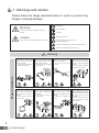
1. Warnings and caution
Please follow the things described below in order to prevent any
danger or property damage.
Warning
Prohibition.
No disassembly
It may cause a serious damage or injury if
violated.
No touch
Caution
Must follow strictly.
It may cause a minor damage or injury if violated.
Shows plugging out the power cord
without an exception
Shows the warning and caution for an electric shock.
Shows the warning and caution for a fire.
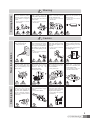
Power & Installation
Warning
2
Please don’t use several
products at the same time on
one power socket.
·It may cause a fire due to an
abnormal overheating.
Please don’t bend the power
cable excessively or it may
cause an electric shock.
·fire when using a damaged
power cable.
Please don’t handle the power
cable with a wet hand.
·It may cause an electric
shock.
Please plug out the power
cable from the socket when
not using it for a long period
of time.
·It may shorten the product
lifespan or cause a fire.
Please don’t install the
product in the place where
there is much oil, smoke or
humidity.
·It may cause an electric
shock or fire.
Please don’t install the
product with the lightening
and thunder.
·It may cause an electric
shock or fire.
Please don’t use and connect
this product with other
products with different rated
voltage
·It may cause a disorder or
fire.
When installing the product
that generates heat, please
install the product away from
the wall (10cm) for the
ventilation.
·It may cause a fire due to
the increased internal
temperature.
Cleaning & Use
Warning
Please don’t disassemble,
repair or rebuild this product
arbitrarily (please contact the
service center if a repair is
needed.
·It may cause an electric
shock or fire.
If an abnormal sound, burning
smell or smoke is coming out
of the product, please plug out
the power cable and contact a
service center.
·It may cause an electric
shock or fire.
Please don’t insert any
metallic or burnable materials
into the ventilation hole.
·It may cause an electric
shock or fire.
Please use only the designated
batteries for the products of
using DC power.
·It may cause an electric
shock or fire.
Cleaning & Use
Power & Installation
Caution
Please plug the power cable
firmly into the inner end
·It may cause a fire.
Please hold the plug tightly
when unplugging the power
cable (a part of the copper
wire may be disconnected if
the grabbing is only made on
the cord when pulling out the
cable).
·It may cause an electric
shock or fire
When connecting the power
cables after cutting the cable,
please install the product with
power off
·It may cause an electric
shock or fire
Please be careful when using
an AC circuit breaker since
there is a possibility of an
electric shock.
Please check the use voltage
and current for the DC-only
products and use the
appropriate rectifier.
·It may cause a fire.
Please avoid direct rays of the
sun or heating devices at a
time of installation.
·It may cause a fire.
When cleaning the product,
please rub it with a soft and
dry cloth after plugging out
the power cable. (Please don’t
use any chemical products
such as wax, benzene, alcohol
or cleanser.)
Please don’t drop the product
on the ground and don’t apply
a shock .
·It may cause a failure.
Please use the designated
connection cable within the
maximum calling distance
designated for the product
·It may reduce the product
performance.
When installing the product,
please fix it firmly while using
the wall-mounting unit and
screws.
·It may cause an injury from
the falling object.
Please don’t install the
product on an unstable place
or small support board.
·It may cause an injury if it
falls down while in use.
3
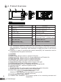
2. Product Overview
No.
1
HANDSET
Description
2
MONITOR
4
MENU BUTTON
3
5
UP BUTTON
RIGHT BUTTON
No.
Description
10
DOOR RELEASE BUTTON
12
MENU BUTTON
11
13
VOLUME CONTROL
SELECT BUTTON
UP BUTTON(△) (ZOOM - IN) /
6
DOWN BUTTON
14
7
LEFT BUTTON
15
POWER SWITCH
8
MONITOR BUTTON
16
CONNECTING TERMINAL
9
INTERPHONE BUTTON
DOWN BUTTON(▽) (ZOOM - OUT)
● This videophone product provides different functionality for connecting the second
door camera(tilt). At the time of booting, the built-in program checks the connectivity
of the second door camera(tilt) and commands to supply the power to the second
camera.
● Therefore, in case of connecting the second camera(tilt), the connection must be
completed before the power is turned on.
4
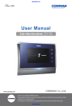
① HANDSET
② MONITOR
③ UP BUTTON : Move to menu or used for tilt function
④ MENU BUTTON : Move to menu for Screen adjustment and Product info.
⑤ RIGHT BUTTON : Move to menu or used for tilt function
⑥ DOWN BUTTON : Move to menu or used for tilt function
⑦ LEFT BUTTON : Move to menu or used for tilt function
⑧ MONITOR BUTTON : Checking visitors' images at the gate.
⑨ INTERPHONE BUTTON : Calling slave interphone.
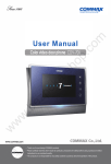
⑩ DOOR RELEASE BUTTON : Releasing the door during the talk.
⑪ VOLUME CONTROL : Adjust the ringtones volume.
⑫ MENU BUTTON
To enter the menu for screen control, mute setting and product information.
⑬ SELECT BUTTON : Press to select an item from the menu.
⑭ UP BUTTON : Move from the menu items to up and right.
("ZOOM IN" used for tilt function)
DOWN BUTTON : Move from the menu items to down and left.
("ZOOM OUT" used for tilt function)
⑮ POWER SWITCH : Power ON/OFF
⑯ CONNECTING TERMINAL : For program update or for connecting cameras and
interphones.
3. How to use
Call from a visitor
① When the visitor calls from the entrance(door camera), the calling sound rings and
the image of the visitor is shown on the screen.
② By picking up the handset, you can talk with the visitor. If you press door release
button, door will be released.(Door release works only while talking and it is possible
only when the door camera is interlocked with door release function.)
③ 3-way communication is possible when another user picks up the handset of
extended interphone, when you are talking with door camera on video door phone.
(Entrance-Household-Interphone simultaneous communication mode)
④ If you put down the phone, talking is finished and turns to stand-by mode.
Call with additional interphone
(1) Call from interphone to video door phone(household)
① The calling sound rings when there is a call from interphone.
② By picking up the handset, you can talk with the person using interphone.
③ Image of visitor is shown on the screen and 3-way communication is possible
between household, interphone and door camera when visitor calls from door
camera, while household is talking with interphone.
(2) Call from video door phone to interphone
① After picking up handset of video door phone, and then press INTERPHONE
BUTTON in order to call the interphone.(Interphone is called only while the
interphone button on household is being pressed.)
② When you receive the call from interphone, enjoy the call.
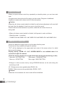
Monitoring : function to see the image of visitor in the entrance.
(On stand-by mode - status of putting handset down ) Operation
- By pressing the Monitor button repeatedly, the monitor will work as following in order.
Camera 1 Camera 2 OFF Camera 1 ......
(One talking mode - status of putting handset up) Operation
- By pressing the Monitor button repeatedly, the monitor will work as following in order.
Camera 1 Camera 2 Camera 1 Camera 2 ......
5
Adjust the volume
When you press volume control key repeatedly on stand-by status, you can hear each
level
of ringtone and volume level will be pop up on the screen. Ringtone of additional
interphone is same with volume level of video door phone.
Caution
When the call volume control switch is clicked for call volume adjustment, call sound will
be heard from the handset 1 time for a user to check the sound.
Please make sure that handset is in position, when the call volume function is
being used.
- When call volume control switch is clicked, it will operate in order as follows.
- (Stand by mode - In position)
- CHIME-VOL0 CHIME-VOL1 CHIME-VOL2 CHIME-VOL3 CHIME-VOL0
CAMERA TILT FUNCTION
Users can adjust the image focus to see the place that they want.
Functions are only available with pan tilt cameras.
"TILT" will be displayed on the upper-right had corner of the screen when it is called
from a pan tilt camera.
Display setting "ZOOM, 4:3, 16:9" SCREEN MODE is not available when it is
connected to pan tilt cameras.
(Click the front key buttons to use pan tilt function during the monitoring or talk.)
* Move left : LEFT BUTTON
* Move down : DOWN BUTTON
* Move up : UP BUTTON
* Move right : RIGHT BUTTON
- Enlarge or reduce screen size by using UP/DOWN buttons on the side during the
monitoring or talk.
UP : Enlarge screen size gradationally (ZOOM - IN)
DOWN : Reduce screen size gradationally (ZOOM - OUT)
Caution
When the unit is restarted, the zoom mode will be innitialized.
6
SCREEN MODE : Adjusting screen ratio.
If you press the UP/DOWN button in order during the monitoring or talk when it is
connected with normal cameras(not pan tilt cameras), the screen ration will be
adjusted.
WIDE : 16:9 screen mode / 4:3 : real ratio of image at the door.
ZOOM: 4:3 screen mode with zoomed in image
("ZOOM, 4:3, 16:9" SCREEN MODE is not available when it is connected to tilt
cameras.)
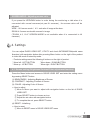
4. Settings
You can adjust DOOR VIDEO SET, UTILITY and check INFORMATION(model name
&version) with navigation button after pressing Menu button on the right of the product
in video talk mode or stand-by mode.
•Products settings need the following 4 buttons on the right of product.
* Move left : LEFT BUTTON
* Move down : DOWN BUTTON
* Move up : UP BUTTON
* Move right : RIGHT BUTTON
4-1. Screen setting (Brightness/Contrast/Color adjustment function)
Press the Menu button and access to DOOR VIDEO SET and enter the setting menu
by pressing SELECT button.
(1) BRIGHTNESS : Adjusting Brightness of Screen
(2) CONTRAST : Adjusting Contrast of Screen
(3) COLOR : Adjusting Color of Screen
※ How to adjust
① Move to Menu you want to adjust with navigation button on the list of DOOR
VIDEO SET
② Press SELECT button to choose an icon.
③ Adjust the set value with navigation button
④ To complete the set, press SELECT button.
(4) RESET : Initializing
※ How to reset.
① Move to RESET menu in DOOR VIDEO SET menu
7
② Press SELECT to enter the menu.
③ Select YES with navigation button
④ Press SELECT button.
(5) EXIT : Go back to setting mode
4-2. UTILITY(additional function)
Press the Menu button and access to Utility SET and enter the menu by pressing
SELECT button.
(1) CHIME-BELL VOLUME : setting volume sound .
① Move to CHIME-BELL VOLUME icon with navigation button in UTILITY Menu.
② Press SELECT to enter the menu.
③ Select the volume sound or not with navigation button.
④ To complete the set, press SELECT button.
(2) EXIT : Go back to Setting menu
4-3. INFORMATION (The function to check Model name & Version)
In order to check the product information, press menu button and move to
INFORMATION menu with navigation button.
(1) MODEL : You can check the model name.
(2) VERSION : You can check the model version.
(3) VIDEO : You can check the video transmission formats(NTSC / PAL)
(4) SOURCE :
You can check the position of camera(DOOR1 / DOOR2) which is shown on
the screen for now.
4-4. EXIT(Finish setting menu)
4-5. RESET : Initializing
Keep pushing interphone and door open button for 3 seconds(Screen setting and
Call volume will be initialized)
Caution
If initialization is activated, all data including screen setting will be
initialized) (Screen setting and Call volume)
8
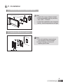
5. Installation
1. Installation Method of camera monitor
SCREW PHM 3X6 ZnY - 1EA
SCREW GH1T 4X18 ZnW
- 4EA
Note
① Avoid the range of direct sunlight
② Recommended height is pertinent
from 1450 ~ 1500mm
③ Avoid the installation near magnetic
activity, humid temperatures and gas
2. Installation Method of camera
Note
① Do not install the camera where
it is exposed to Direct sunlight
② Keep cleaning up its lens to
capture good views.
9
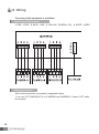
6. Wiring
The wiring of this equipment is as follows.
Camera connector polarity
1. RED : VOICE 2. BLUE : GND 3. YELLOW : POWER(+12V) 4. WHITE : VIDEO
Wiring precautions
Each device should be connected by separated cables.
If you use UTP CABLE[CAT.5] for CAMERA1and CAMERA2, 2 lines of UTP cable
are required.
10
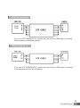
DOOR Camera Wiring
CAM1
CAM2
• If you use UTP CABLE[CAT.5], connect the rest 4 lines to GND after connecting
4 lines between monitor and camera.
INTERPHONE Wiring
• If you use UTP CABLE[CAT.5], connect the rest 4 lines to GND after connecting
4 lines between monitor and interphone.
11
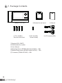
7. Package Contents
① Body of CDV-70KPT
④ T4 X 18(4EA)
Screw for wall mount
② Bracket for wall mount
⑤ M 3 X 6(1EA)
Screw for body
① Monitor(CDV-70KPT)
② Wall bracket for monitor
③ User Manual
④ Mounting Screw (SCREW GH1T 4X18 ZnW) – 4EA
⑤ Monitor fixing screw (SCREW PHM 3X6 ZnY) – 1EA
⑥ Connector (CONN. 4PX300) – 2EA
12
③ Manual
⑥ 4P Connector(2EA)
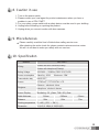
8. Caution in use
1. Turn on the power switch.
2. Please contact your local agent for product maintenance when you have a
problem in use of CDV-70KPT
3. For your safety, power switch with a safety device must be used in your building.
4. Unplug before installing or repairing the product.
5. Unplug when you connect monitor with door cameras.
9. Miscellaneous
● Please carefully read this User's Guide before calling service man
After checking the entire check list, please contact customer service center.
We will do our best to make you satisfy with our services.
10. Specification
MODEL
Wiring
Rating Voltage
CDV-70KPT
4 wires with door camera(Polarity)
4 wires with interphone(Polarity)
100-240V~, 50/60Hz (FREE VOLTAGE)
Power consumption
Stand-by : 4.5W
Screen
17.78Cm(7") TFT-DIGITAL LCD
Transmission way
Ringtone
Screen Display
HAND SET
Maximum : 16W
Entrance : electronic chime
Interphone : electronic buzzer
Monitoring : 30 ±5sec , Talk : 60 ±5sec
Cable thickness
0.5mm
0.65mm
0.8mm
Distance
28m
50m
70m
Working temperature 0 ~+40℃ (32℉ ~ 104℉)
Dimension
311(W) X 168(H) X 32(50.3)(D)
13
513-11, Sangdaewon-dong, Jungwon-gu, Seongnam-si, Gyeonggi-do, Korea
Int’l Business Dept. Tel. : +82-31-7393-540~550 Fax. : +82-31-745-2133
Web site : www.commax.com
PM0270KPT010
Printed In Korea / 2014.08.104