1
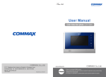
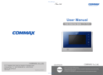
User Manual Color video door phone CDV-70P 513-11, Sangdaewon-dong, Jungwon-gu, Seongnam-si, Gyeonggi-do, Korea 513-11, Sangdaewon-dong, Jungwon-gu, Seongnam-si, Gyeonggi-do, Korea Business Dept. : +82-31-7393-540~550 : +82-31-745-2133 Int’l Int’l Business Dept. Tel. Tel. : +82-31-7393-540~550 Fax.Fax. : +82-31-745-2133 : www.commax.com WebWeb site site : www.commax.com PM0770P00010 Printed In Korea / 2011.10.104 • Thank youpurchasing for purchasing COMMAX products. • Thank you for COMMAX products. before a product and follow • Please carefully this User’s Guide (in particular, precautions for safety) • Please carefully read read this User’s Guide (in particular, precautions for safety) before usingusing a product and follow instructions toause a product exactly. instructions to use product exactly. • company The company not responsible forsafety any safety accidents caused by abnormal operation the product. • The is notisresponsible for any accidents caused by abnormal operation of theofproduct. Greetings ● Thank you for choosing COMMAX. ● Please read this manual carefully before you use the product. Table of contents Greetings ..................................................................................................................1 Contents table ...........................................................................................................1 1. Warnings and caution ...........................................................................................2 2. Product Overview..................................................................................................4 3. Operation Methods ...............................................................................................5 4. Settings .................................................................................................................6 5. Installation .............................................................................................................8 6. Wiring ...................................................................................................................9 7. Part lists ..............................................................................................................11 8. Caution in use ....................................................................................................12 9. Miscellaneous .....................................................................................................12 10. Specification......................................................................................................12 1 1. Warnings and caution Please follow the things described below in order to prevent any danger or property damage. Prohibition. Warning No disassembly It may cause a serious damage or injury if violated. No touch Caution It may cause a minor damage or injury if violated. Must follow strictly. Shows plugging out the power cord without an exception Shows the warning and caution for an electric shock. Shows the warning and caution for a fire. Power & Installation Warning 2 Please don’t use several products at the same time on one power socket. ·It may cause a fire due to an abnormal overheating. Please don’t bend the power cable excessively or it may cause an electric shock. ·fire when using a damaged power cable. Please don’t handle the power cable with a wet hand. ·It may cause an electric shock. Please plug out the power cable from the socket when not using it for a long period of time. ·It may shorten the product lifespan or cause a fire. Please don’t install the product in the place where there is much oil, smoke or humidity. ·It may cause an electric shock or fire. Please don’t install the product with the lightening and thunder. ·It may cause an electric shock or fire. Please don’t use and connect this product with other products with different rated voltage ·It may cause a disorder or fire. When installing the product that generates heat, please install the product away from the wall (10cm) for the ventilation. ·It may cause a fire due to the increased internal temperature. Cleaning & Use Power & Installation Cleaning & Use Please don’t disassemble, repair or rebuild this product arbitrarily (please contact the service center if a repair is needed. ·It may cause an electric shock or fire. Warning If an abnormal sound, burning smell or smoke is coming out of the product, please plug out the power cable and contact a service center. ·It may cause an electric shock or fire. Please don’t insert any metallic or burnable materials into the ventilation hole. ·It may cause an electric shock or fire. Caution Please plug the power cable firmly into the inner end ·It may cause a fire. Please hold the plug tightly when unplugging the power cable (a part of the copper wire may be disconnected if the grabbing is only made on the cord when pulling out the cable). ·It may cause an electric shock or fire When connecting the power cables after cutting the cable, please install the product with power off ·It may cause an electric shock or fire Please be careful when using an AC circuit breaker since there is a possibility of an electric shock. Please check the use voltage and current for the DC-only products and use the appropriate rectifier. ·It may cause a fire. Please avoid direct rays of the sun or heating devices at a time of installation. ·It may cause a fire. When cleaning the product, please rub it with a soft and dry cloth after plugging out the power cable. (Please don’t use any chemical products such as wax, benzene, alcohol or cleanser.) Please don’t drop the product on the ground and don’t apply a shock . ·It may cause a failure. Please use the designated connection cable within the maximum calling distance designated for the product ·It may reduce the product performance. Please use only the designated batteries for the products of using DC power. ·It may cause an electric shock or fire. When installing the product, please fix it firmly while using the wall-mounting unit and screws. ·It may cause an injury from the falling object. Please don’t install the product on an unstable place or small support board. ·It may cause an injury if it falls down while in use. 3 2. Product Overview No. 1 2 Microphone 4 3 5 6 7 8 9 4 Monitor Description No. 10 Description Call Sound Level Control 11 Menu Button On/Off & status LED 13 Up Button (△) Interphone Button 15 Speaker Monitor Button Door Release Button Talk Button Talk Sound Level Control 12 Select Button 14 Down Button (▽) 16 Connector Terminal Power Switch 1. Monitor : You can check the visitor. 2. Microphone : You can talk with the visitor. 3. Speaker : You can hear the calling sound from the door camera. 4. On/Off & status LED : Show blue light when the monitor is turned on, no light when off. 5. Monitor Button : Press to see images from camera. 6. interphone Button : Press to call interphone. 7. Door Release Button : Press to open the door. 8. Talk Button : Press to talk with door camera. 9. Talk Sound Level Control : Use to adjust sound level during talking. 10. Call Sound Level Control : Use to adjust sound level of calling sound. 11. MENU Button : Press to enter Menu for display adjustment, calling sound setting, product information etc. 12. Select Button : Press to select on menu. 13. Up Button : Press to move up on menu. 14. Down Button : Press to move down on menu. 15. Power Switch : Used to turn on/off power of the product. 16. Connector Terminal : Used to connect other devices like door camera, door panel, or program update tool. 3. Operation Methods 3-1. Receiving a calling from visitor. ① When the call button is pressed by a visitor on the door camera, the melody shall be rung and visitors' image is shown on the screen (If you do not press the Talk Button, the display will be shown up for 30 seconds and turned off automatically). ② By pressing the Talk Button, you are able to talk with visitor. By pressing the Door Release Button, you can open the door for visitor(Door release function can be done only when the monitor is showing the visitor, on the camera which has door release function.) ③ When monitor and door camera are on talking, the 3-party talking is possible by picking up receiver of the interphone. (Camera-Monitor-Interphone talking at same time.) ④ By pressing Talk Button again you can end the talking and monitor comes back to stand-by mode. 3-2. Talk with Interphone. (1) Calling from the Interphone. ① You will hear calling sound when interphone call the monitor. ② Press Talk Button to talk with the interphone. ③ When monitor and interphone are on talking, the 3-party talking is possible by calling from the door camera. (Camera-Monitor-Interphone talking at same time.) (2) Calling the interphone from the monitor. ① Press Talk Button and Interphone Button in order to call the interphone from the monitor. (Interphone button should be pressed & held until the interphone answers.) ② Then talking is available by picking up the handset of interphone. 3-3. Monitoring : To see the visitor at the door. (On stand-by mode) Operation - By pressing the Monitor button repeatedly, the monitor will work as following in order. Camera 1 Camera 2 OFF Camera 1 ...... (On talking mode) Operation - By pressing the Monitor button repeatedly, the monitor will work as following in order. Camera 1 Camera 2 Camera 1 Camera 2 ...... Caution : When you use only 1 camera, please connect the short pin(jumper), which is included in product packing, to the terminal“Camera 2 Select” on the back side of the product. (When the short pin is connected, the camera 2 does not work.) 5 4. Settings On talking or monitoring mode, press menu button on the right side of product, and press △/▽ buttons to adjust display(brightness, contrast, color), to enter the Utility menu, to check the product information. •Following 4 buttons on the right side of the product are used for setting. * Menu, End : MENU * Select, Input : SELECT * Move up, right : △(UP Button) * Move down, left : ▽(DOWN Button) 4-1. Display Setting (Brightness, Contrast, Color Adjustment) On Setting Mode, move to Door Video Set and press Select button to enter the display setting mode. (1) BRIGHTNESS : To adjust brightness. (2) CONTRAST : To adjust contrast. (3) COLOR : To adjust color. ※ How to adjust ① On DOOR VIDEO SET display press △/▽ to move to the item you want to adjust ② Press Select Button to select the item. ③ Adjust using △/▽ buttons. ④ Press Select Button again to finish. (4) RESET : Puts back settings to initial setting. ※ How to reset. ① On DOOR VIDEO SET display move to RESET item. ② Press SELECT Button to select the item. ③ Select YES using △/▽ buttons. ④ Press SELECT button to reset. (5) EXIT : Return to Configuration mode ※ Setting ① Click △/▽ button to move to EXIT in DOOR VIDEO SET menu ② Click SELECT button 4-2. UTILITY(Extra features) Move to UTILITY and click SELECT button to enter below menu (1) CHIME-BELL MUTE : Set call sound mute function ① Move to UTILITY from configuration mode and click SELECT. Then, move to CHIME-BELL MUTE using △ /▽ button 6 ② Click SELECT button ③ Control the volume with △/▽ button : Bell on / : Bell off ④ After the setting, click SELECT button (2) EXIT : Return to configuration mode ※ Setting ① Move to EXIT in UTILITY MODE by using △ /▽ button ② Click SELECT button to choose 4-3. INFORMATION (Model and Version checking) Click △/▽ button to check the Model and version in configuration mode (1) Model : The name of Model (2) Version : The version of the product (3) VIDEO : The video type of the product (4) SOURCE : The location of the image 4-4. EXIT(End configuration) Move to EXIT and click Select button. 7 5. Installation 1. Installation Method of camera monitor Note ① Avoid the range of direct sunlight ② Recommended height is pertinent from 1450 ~ 1500mm ③ Avoid the installation near magnetic activity, humid temperatures and gas 2. Installation Method of camera Note ① Do not install the camera where it is exposed to Direct sunlight ② Keep cleaning up its lens to capture good views. SCREW T4X18(2EA) SCREW M3X8(1EA) 8 DRC-40CK 6. Wiring CAMERA CONNECTOR POLARITY 1. RED : VOICE 2. BLUE : GND 3. YELLOW : POWER(+12V) 4. WHITE : VIDEO CAMERA2 SELECT : Decide if you use Camera No.2 or not (Please insert the enclosed short pin, if you do not want to use Camera No.2) Caution on the Wiring Be sure to use a separate wiring for each connect 2lines of UTP CABLE[CAT.5] are required if UTP CABLE[CAT.5] is used for CAMERA1 and CAMERA2 9 DOOR Camera Wiring • If UTP CABLE[CAT.5] is used, use 5 lines for GND line. INTERPHONE Wiring • If UTP CABLE[CAT.5] is used, use 5 lines for GND line. 10 7. Part list ① Body of CDV-70P ② Bracket for wall mount ③ Manual ④ GH1T 4 X 18 ZnY Screw for wall mount ⑤ PHM 3 X 6 ZnY Screw for body ⑥ 4P(2EA) Connector ⑦ 2P SHUNT Only No. 1 camera is available if you insert 2P shunt(short pin) ① Monitor(CDV-70P) ② Wall bracket ③ Manual ④ Mounting Screw (SCREW GH1T 4X18 ZnY) – 4EA ⑤ Monitor fixing screw (SCREW PHM 3X6 ZnY) – 1EA ⑥ Connector (CONN. 4PX300) – 2EA ⑦ Camera 2 Short pin (PIN 2P SHUNT(A2095)) – 1EA 11 8. Caution in use 1. Turn on the power switch. 2. Please contact your local agent for product maintenance when you have a problem in use of CDV-70P 3. For your safety, power switch with a safety device must be used in your building. 4. Unplug before installing or repairing the product. 5. Unplug when you connect monitor with door cameras. 9. Miscellaneous ● Please carefully read this User's Guide before calling service man After checking the entire check list, please contact customer service center. We will do our best to make you satisfy with our services. 10. Specification MODEL CDV-70P Transmission way Door camera 4wires (Polarity), interphone 4wires (polarity) Power consumption On stand-by : 3.5W Monitor 7" TFT-DIGITAL LCD Rating Voltage Transmission way Call sound Display Distance 100V-240V~, 50/60Hz (FREE VOLTAGE) On talk: 15W HANDS FREE (Voice switch circuit) Door : Electronic chime (Sol Mi Do), interphone : Beep Monitoring : 30 ±5sec , Talk : 60 ±5sec Pie 0.5mm 28m Working temperature 0 ~+40℃ (32℉ ~ 104℉) Dimension 12 0.65mm 50m 243.0(W) X 168.0(H) X 30.0(D) 0.8mm 70m