1
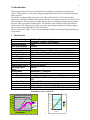
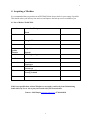
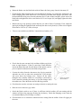
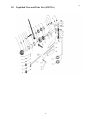
AWP3.7 Wind Generator
Owners Manual
Version 1.1
African Windpower
[email protected]
www.africanwindpower.com
© 2007 African Windpower
2
Contents
1.
2.
3.
4.
Safety Warning
Introduction
Specifications
Acquiring the a machine
4.1 Purchasing-Dealer List
4.2 Shipping
4.3 Unpacking the Machine
4.4 List of Equipment Supplied
5. Pre Installation Planning
5.1 Siting the Wind Generator
5.2 Towers and Rigging
5.3 Cables and Controller
5.4 Tools and Equipment Required
6. Assembly Instructions
6.1 Controller Installation
6.2 Wind Turbine Assembly
7. Inspection and Maintenance
8. Fault Finding
9. Drawings and Spare Parts List
10. Warrantee
11. One last thing
2
3
4
4
5
5
6
6
6
7
7
7
8
9
10
13
14
15
16
17
3
Safety Warning !
1. Electrical Shock hazard
The Wind generator can produce higher than nominal voltages when
running open circuit. This is especially dangerous with the higher voltage
machines which can produce over 500 volts. Keep the output wires
shorted initially and carefully follow the installation instructions.
2. The AWP3.7 is a heavily built machine and can cause injury if not
assembled and erected carefully, according to the instructions and using
the correct equipment.
3. Do not approach the machine while the blades are spinning-they can
cause serious injury!
Notice
African Windpower has made every effort to ensure that the information
presented in this manual is accurate but assumes no responsibility for any
errors or omissions. Users of this information and AWP products assume full
responsibility and risk.
3
4
2. Introduction.
This manual contains all necessary information for assembling, operating and maintaining the
AWP3.7 Wind generator, in the battery charging configuration, please read it carefully and retain for
future reference.
The AWP3.7 is ruggedly built, in the style of the ”Heavy Metal School”. The 30 pole machine
operates at a relatively low RPM, which together with only 3 moving parts, ensures very long life with
little maintenance. The high efficiency blades sweep a large area, ensuring maximum energy capture
from low wind speeds other machines ignore. The machine is also suitable for high winds with the
simple, upwind side furling gravity return yaw system, protecting the machine by reliably swinging
the rotor out of winds faster than 12 m/sec (40 Km/Hr).
Other versions of the AWP3.7 can be used for Building Heating, Electric Water Pumping and Inverter
Grid Connect.
3. Specifications.
Peak Power Rating
Rated Wind Speed
Start up wind Speed
Cut in Wind Speed
Energy Production
Alternator Design
Electrical Output
Rotor Diameter
Maximum RPM
Number of Blades
Blade Construction
Speed/Power Control
Max Design Wind
Speed
Configuration
Corrosion protection
Cable Connection
Tower Top Mounting
Tower Top Weight
Controller
Dump Load
Shipping dimensions
1500 Watts Battery Charging
2000 Watts – Inverter - Grid Connect
12m/s
3.5m/sec
3m/sec
3m/s 4KWHr/Day - 4m/s 7KWHrs/Day – 5m/s 10KWHr/day
30 Pole (Ceramic Magnet) Rotor, Laminated Axial Stator
3 Phase 'Wild' AC, 0-125Hz, 12V,24V,36V,48V,96V,110/220V
3.7 Meters
500
3
GRP Composite design
Gravity Yaw System
60m/sec
Upwind Rotor – furling tail
Epoxy coated / Marine version hot dip galvanised
Heavy duty slip rings
3 Inch (80mm NB) Table D Flange - (4 x M16 Bolts on 150mm
PCD)
110Kgs (220 Pounds)
Turbine Side diversion dump control
Wall mounted resistive heater 2000W
150Kgs (308 Pounds) Crate 1900x 570x 540mm (74x23x21ins)
Performance Curves (AWP3.6)
12000 Whr
1600
1200
Daily Energy Production
10000 Whr
AWP36 Power Curves
8000 Whr
1000
12 V
24 V
36 V
48 V
220 V
800
600
400
200
12 V
6000 Whr
24 V
36 V
4000 Whr
48 V
220 V
2000 Whr
2.0 m/s 3.0 m/s 4.0 m/s 5.0 m/s 6.0 m/s 7.0 m/s
5 mph 7 mph 9 mph 11 mph 14 mph 16 mph
13
Wind Speed (M/s)
11
9
7
5
3
0
1
Power O/P (W)
1400
Mean windspeed
4
5
.
4. Acquiring a Machine
It is recommended that you purchase an AWP Wind Turbine from a dealer in your country if possible.
This should reduce your delivery time and cost, and improve the back up service available to you.
4.1 List of Dealers World Wide
Australia
Australian Windpower
Perth
Canada
France
Krug SARL
Greece
Kenya
Uganda
Tanzania
Namibia
Digital Communications
Nairobi
HPS Engineering
New Zealand
South Africa
South Africa
UK
Otto Solar
Uppington
Jacobs Electrical
Carnarvon
Scoraig Wind Electric
Scoraig Scotland
USA
If this is not possible then African Windpower can supply you directly from Johannesburg
South Africa by Sea or Air or put you in touch with your nearest dealer.
Contact : Oloff Smyth [email protected] +27 84 4444118
5
6
4.2 Shipping Crate Dimensions
A complete AWP.3.7 with Controller and Dump Load is packed into a wooden crate
1950mm x 550mm x 550mm (74”x 24”x 24”) weighing 145Kgs (250Pounds).
4.3 Unpacking the Crate
The crate lid is secured with 6 posi-drive screws marked by red circles. After removing the blades and
tail booms, the two blocking braces should be removed by unscrewing 4 posi drive screws on the sides
of the crate also marked by red circles.
4.4 List of Equipment Supplied
QTY
1
1
1
1
1
3
1
1
1
1
3
4
7
2
1
2
1
3
6
3
3
3
1
1
DESCRIPTION
ALTERNATOR (OF CHOSEN VOLTAGE)
YAW HEAD EQUIPED WITH SLIP RINGS AND TAIL HINGE PIN FITTED
TAIL BOOM FRONT SECTION
TAIL BOOM REAR SECTION
TAIL FIN SET
BLADES –( BALANCED SET)
NOSE CONE
CONTROLLER
DUMP LOAD
FITTINGS KIT CONTAINING THE FOLLOWING :
ALTERNATOR MOUNTING BOLTS M16 X 30MM , STAR WASHERS
YAW HEAD MOUNTING BOLTS M16 X 50 , NYLOCK NUTS, WASHERS
TAIL FIN BOLTS M8 X 60MM , NYLOCK NUTS AND WASHERS
TAIL BOOM CLAMP BOLTS M8X 100MM, NYLOCK NUTS , WASHERS
TOP CAP
TOP CAP BOLTS M6X 15, WASHERS
CABLE SUPPORT THIMBOLE, M8 BOLT, NYLOCK NUT, 40MM WASHER
NOSE CONE BOLTS M6 X 30MM, WASHERS
BLADE BOLTS M12 , NYLOCK NUTS, WASHERS
BLADE CLAMPING PLATE
BLADE CLAMPING PAD
NOSE CONE MOUNTING BRACKET
TOWER TOP FLANGE AND 4 GUSSETTS
USER MANUAL
6
7
5 Pre Installation Planning
5.2 Siting The Wind Turbine
Smooth, laminar airflow
2H
Turbulent airflow
H
2H
20 H
Turbulent airflow created by obstructions (Ad. P.Gipe, 93)
To ensure good performance from the Wind Generator it is important that care is taken in the siting
of the machine.
Buildings, trees and rocky outcrops etc disrupt the smooth flow of wind creating a
wind shear with the wind velocity nearer the ground being slower than higher up.
Turbulence is also created by these obstructions. Turbulence is detrimental as the swirling air
causes the Turbine to continuously yaw increasing stress and wear and tear on components and
reducing the useful life of the equipment. Therefor, as a general rule the Turbine should be
mounted twice as high as any such obstructions. The power obtained from the wind is proportional
the cube of the wind speed, and the wind speed increases with height from the ground. A 26%
increase in wind speed from a higher tower will yield a 100% increase in power from the turbine.
A little more money spent on a higher tower will harvest the same power as 2 machines!
Preference should be given to the prevailing wind direction but it should be noted that tall features
behind the Turbine can also slow down the wind flow through the turbine.
5.3 Tower and Rigging
Great care should be taken in the selection and preparation of the wind turbine tower as this is the most
difficult and crucial aspect of the entire installation. Towers can be the triangulated self supporting
type used with traditional wind rose water pumps however they are normally about 8 meters high with
surrounding established trees out growing them. Greater heights can only economically be achieved
with guyed towers. They can be tubular tilt up or fixed lattice types. Tilt up towers permit assembly
and maintenance on the ground while latticed towers make climbing easier and safer.
In all cases it is imperative that the turbine should be mounted on a 90mm pipe extending at least
1700mm from the last flange to which the guys or structure is attached.
There should be a minimum of 300mm measured horizontally from the lowest tip of the blade to any
part of the tower. Many blades have had their tips shattered when this has not been observed.
A separate manual covering towers in detail is available.
7
8
5.4 Cables, Controller and Battery Bank
The table below indicates the correct cable size for various cable runs.
Machine
12 Volt
24 Volt
36 Volt
48 Volt
110 Volt
220 Volt
20 Meters
10mm
10mm
6mm
6mm
4mm
2.5mm
50 Metres
16mm
10mm
10mm
6mm
4mm
2.5mm
100 Meters
25mm
16mm
16mm
10mm
6mm
4mm
200 Meters
35mm
25mm
25mm
16mm
10mm
4mm
5.5 Tools required.
1
1
1
1
1
1
1
1
1
1
1
1
1
1
10MM COMBINATION SPANNER OR SOCKET
13MM COMBINATION SPANNER AND SOCKET
17MM SPANNER
19MM COMBINATION SPANNER OR SOCKET
24MM COMBINATION SPANNER AND SOCKET
SOCKET DRIVER
SHIFTING SPANNER/ADJUSTABLE WRENCH 250MM/12INCH
SCREW DRIVER
SIDE CUTTERS
CRIMPING TOOL
SMALL HAMMER
TEST METER
DRILLING MACHINE AND 9MM DRILL BIT
LOCKTITE
5.6 Other Items Required
Insulation Tape
FlexibleDrop Cable and Lugs to suit
Armoured 3 core cable or house wire and conduit
Batteries, Clamps and Battery cable
Charger Fuse
Main Battery Fuse
Inverter and AC Wiring
8
9
6 Assembly Instructions
•
Install the Controller, Dump Load, Battery, Fuses and Cables first so that you can control the
Turbine when the tower is lifted, in a safe and orderly manner.
•
It is best to assemble the machine while on the ground, onto a lowered tilt-up tower, which can
then be raised. Due to the considerable weight of the generator (125 kg), it is difficult and
dangerous to attach it to a tower already erected.
•
Before assembling the turbine to the tower top, the tower should be first be assembled and raised,
all rigging should be adjusted to ensure that the tower is straight and vertical, so that the tower can
de raised and lowered with out problems
•
Although one person can assemble the machine with mechanical aids, it is advisable to have an
assistant since many parts are heavy and cumbersome to manoeuvre into position. At least two
people are needed to raise the machine.
•
Keep the alternator wrapped in the plastic sheeting as long as possible to prevent dirt or metal
objects from entering the alternator and becoming lodged between the magnets and the rotor.
•
Check that all components as listed are present. Open the yaw head inspection door and check the
slip ring brushes are running true and all the connections are tight.
6.1 Charge Controller and Dump Load
The charge controller supplied by AWP contains a three phase rectifier, a DC meter, a Dump Load
Controller, and a Turbine Brake Switch.
The terminals are marked as shown below. The three cables from the alternator connect to the Brass
screw terminals marked L1, L2 and L3.
The Battery and Dump Load must be connected to the Marked Terminals using 6mm lugs .Take care
not to reverse the Battery Cables as this WILL damage the rectifier diodes.
The controller should be located near the batteries in a well ventilated, dry room.
The battery should be protected by fuses to the controller and the load (inverter etc).
Do not use only one fuse as the inverter could be left connected directly to the wind turbine in the
event of the fuse blowing and could be damaged if the dump load circuit was not connected or
functioning correctly.
9
10
Make sure that the cables from the controller to the battery and the dump load are both rated for the
full output current of the turbine.
Make sure the links and connections in the Dump Load are correct for the voltage of the system, and
And are all tight.
CAUTION : Before removing the short on the alternator wires make sure all the controller
connections are correct and secure. ( If you allow the turbine to run and feed power to the controller
with no battery or dump load connected, the resulting high voltages will destroy the PWM circuit and
possibly the rectifiers.
Dump Load and Controller
Open Controller
10
11
Controller Schematic
Diagram
Inter Connections
11
12
Wind Turbine Assembly Procedure :
Slip Ring Version
Yaw Head
a. The top of the lowered tower should be supported about 1,5 meters off the ground. (1)
b. Drill a 9mm hole through the tower pipe 60mm from the top flange(2).
c. Pull the drop cable through the tower with fence wire or something suitable, make a loop 300mm
from the end, place it over the thimble and secure with cable ties (3).
1
2
3
d. Attach the yaw head to the top flange loosely with one of the M16 x 50 bolts (3)
e. Connect the three cables from the slip rings in the yaw head to the three drop wires using split
nuts, crimped ferrules or crimped lugs bolted together. Take great care to insulate the connections
with a large amount of insulation tape to prevent wear through due to vibrations (4).
f. Through the drilled hole, bolt the thimbol to the internal side wall of the tower pipe making sure
the large flat washer is on the inner side of the thimbol (3)
g. Push the joined cables into the tower and secure the yaw head with the remaining bolts (4).
h. Swing the yaw head up into position and tighten the 4 x M16 x 50mm bolts(5)
i. Fit and secure the top cap with the two M6 x 15mm bolts (6).
4
5
6
12
13
Alternator
j. The alternator weighs about 75 Kgs and is very awkward to hold, so plan this carefully. The tail
gate of a pick up works well, or you could use a wheel barrow or drum etc. (7)
k. Line up the bolt holes and pass the cables through the correct hole provided. Take care not to crush
the cable while doing this and tighten the 24mm bolts with lock washers after first putting some
lock tight on the threads (8)
l. Screw one blade stud (short threaded end) into one hole in the front of the alternator. Ensure the
leads are not touching each other or parts of the yaw head. Use the blade bolt to turn the alternator
– it should turn freely. Short the three leads together and turn again It should be difficult to turn
(9).
m. Bolt the other 5 blade bolts into place (short threads into alternator) (9).
7
8
9
Tail
n. Remove the tail hinge pin and attach the front tail boom section (10). Tighten the tail hinge pin nut
so that the bolt is tight against the lugs and can not turn (11)..
o. Attach the rear tail boom section the front section using the two angle clamps and M8 x 100mm
bolts.
p. Attach the tail fins to the rear tail boom section with M8 x 60 bolts and make sure the two M5 anti
rattle bolts are fitted to the top and bottom of the tail fin (12).
10
11
12
13
14
Blades
q. Mount the blades onto the blade bolts with the flatter side facing away from the alternator(13)
r. Fit the flexible blade clamping pads onto the blade bolts directly over each blade, followed by the
blade clamping plates, then fit the nose cone brackets to the blade bolts between the blades, with
the threaded tabs facing away from the alternator face. Fit the washers and M12 nylock nuts to the
blade bolts and tighten the nuts on one blade to 10 N-m of torque (14) and lightly tighten the other
two blades.
s. Measure the tip to tip spacing to ensure that they are with in 5mm of each other. If not, adjust the
spacing by holding the tightened blade and bump the other two by hand (16). When correct tighten
all the nuts to 20 N-m (15 ft lbs) of torque.
t.
Fit nose cone and bolt on with M6 x 30mm bolts and washers (15).
13
14
15
u. Check that the rotor can turn freely and that te blades pass by the
tower at equal distances,. If there is more than 15mm difference
loosen the blade bolts and fit small shims of thin plastic (such as
pieces of plastic bottles)between the blade and generator.
v. Connect the cables from the alternator to the slip ring terminals
and make sure all is in order in the terminal box. Close the door
and screw down the locking screw. Connect all the cables
through to the controller. Make sure everything is connected up
in the controller including the battery, to prevent damage when
the turbine runs. Place the brake switch in the Stop position.
w. Check that the rotor has resistance to turning resistance to turning the rotor.
x. Raise the tower and secure guy cables.
y. Switch the Brake switch to run. If there is sufficient wind the turbine will start turning and the
ammeter will show the amperage flowing into the battery. Check that Dumping occurs when the
reccomended Battery Float Voltage is reached.
z. Check that there is no vibration or untoward noises coming from the turbine. Secure all rigging on
the tower.
14
15
8. Inspection and Maintenance
a. Wind Turbine- The turbine has been designed to operate with a minimum of maintenance.
• Every 6 months check excessive twisting of the electrical cables inside the tower and if
necessary disconnect at tower base and untwist (Non Slip Ring Versions). Listen for
unusual alternator or blade noise and look for excessive vibration which would all call for
close inspection.
• Inspect the blades for leading edge ware and apply grease to all lubricating points. This
should be done either by lowering the tower or by climbing it.
b. Tower
Every 6 months
• Check that the guys are tight. Check that the guy cable clamps are tight by ensuring that
there is still a slack loop between the upper most clamp and the next lower one.
• Check that the shackles are tight.
• Check that the stay rod bolts are still locked together.
• Check all cables for excess fraying or rust.
Every 12 months
• Check the upper guy joints for wear and rust
• Paint all exposed metal parts.
9. Fault Finding
Symptoms
Turbine Fails to Turn
in good wind
Turbine turns slowly in
good wind
Turbine growls and
amps are low
Low output batteries
flat
Turbine vibrates
excessively
Turbine fails to swing
into the wind
Turbine running at
high speed no output
Possible Causes
Shorted cables
Shorted diodes
Failed bearings
Foreign body in
generator
Partial short in cables
1 diode short
1 phase open circuit
Faulty diodes
Insufficient wind
High power usage
Blades out of balance
Yaw bearing worn
Tower top not vertical
Yaw bearing worn/
broken
Cables disconnected
Battery Fuse blown
Controller Ammeter
open circuit
15
Solutions
Remove short
Replace faulty diode(s)
Replace
Remove obstruction
Remove short
Replace diode
Repair open circuit
Replace diodes
Improve tower
siting/height
Economise on power use
Check blade
geometry/balance
Replace yaw bearing
Adjust guy cables
Replace yaw bearing
Fix cables
Replace fuse
Replace meter
16
10. Exploded View and Parts List (AWP3.6)
16
17
11. Warrantee
African Windpower Warrantee
Wind generators, controllers, and associated equipment manufactured by African
Windpower and distributed by Distributor are warranted against defects in
design, material, and workmanship for normal use for which intended. The
warranty period extends one year from installation or two years from the date of
purchase by the user, whichever comes first. During the warranty period AWP
will repair or replace, at its option, defective components and assemblies. In
__COUNTRY__ warranty service for AWP is provided by Distributor.
Customers should ship defective components and assemblies to Distributor at
their own expense for repair or replacement. Return shipping will be provided.
Please call Distributor and make arrangements before shipping.
This limited warranty does not cover the following:
Towers, equipment, materials, or supplies not manufactured by AWP.
AWP equipment that has been improperly installed or modified without approval
from AWP or Distributor
Damage or loss from winds in excess of 45 m/s (100 mph)
Lightning damage or other acts of God.
Incidental or consequential damages.
AWP reserves the right to make design changes, improvements, or additions to its
products without obligation to install such changes or improvements in existing
products.
This warranty may be extended to five years by the purchase of an extended
warranty. The extended warranty shall have the same terms and conditions,
except it shall be in force for 5 years from the date of installation.
17
18
12. One last thing
Try not to get friends like this to help…
18