1
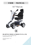
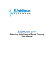
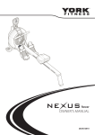
NOTE
Thank you for purchasing
the SPIRIT Studio Rowing
Machine. Please read
carefully through all
the precautions and
instructions in this
manual before using this
equipment and keep this
manual for your future
reference.
STUDIO
ROWING MACHINE
SERVICE CENTRE
NUMBER
For immediate help with
assembly or for additional
product information,
please call our service
center.
(DBN)
031 702 5784
(JHB)
011 907 1660
(CT)
021 934 0862
(PE)
041 487 0573
please have your model
name ready when you
call us.
MAXIMUM USER
WEIGHT
110kg
INSTRUCTION AND USER’S MANUAL
10170
CONTENTS
SAFETY PRECAUTIONS
page 1
PRE-ASSEMBLY CHECK LIST
page 2
PARTS LIST
page 3-4
HARDWARE PARTS LIST
page 5
EXPLODED DIAGRAM
page 6
ASSEMBLY INSTRUCTION
page 7-9
HOW TO STORE YOUR ROWER page 10
MONITOR INSTRUCTION
page 11
EXERCISE INSTRUCTIONS
page 12-13
WARRANTY INFORMATION
page 14-16
SAFETY PRECAUTIONS
10170
To reduce the risk of serious injury, read the following safety instructions before using the Spirit
Studio Rowing Machine.
1.
2.
3.
4.
5.
Use the Spirit Studio Rowing Machine only on a level surface.
Keep children and pets away from this equipment at all times.
The Spirit Studio Rowing Machine should not be used by persons weighing more than 110kgs.
The Spirit Studio Rowing Machine should be used by only one person at a time.
Be careful to maintain your balance while using, mounting, dismounting, folding, unfolding
or assembling the Spirit Studio Rowing Machine. Loss of balance may result in a fall and / or
serious bodily injury.
6. Use the Spirit Studio Rowing Machine only as described in the manual.
7. Do not attempt to adjust the seat position while you are on the Spirit Studio Rowing Machine.
8. Before using this equipment to exercise, ensure you warm up properly, by doing stretching
exercises.
9. Always make sure all bolts and nuts are tightened prior to each use.
10.Always wear appropriate workout clothing and shoes when exercising, do not wear robes or
other clothing that could become caught in the equipment.
WARNING:
Before starting any exercise or conditioning program you should consult with your personal
physician to see if you require a complete physical exam. This is especially important if you are
over the age of 35, have never exercised before, are pregnant, or suffer from any illness.
page-1
PRE ASSEMBLY CHECK LIST
10170
Thank you for choosing the Spirit Studio Rowing Machine. We took great pride in producing this
quality product and hope it will provide you with many hours of quality exercise to make you feel
better, look better and enjoy life to its fullest.
Yes, it’s a proven fact that a regular exercise program can improve your physical and mental health.
Too often, our busy lifestyles limit our time and opportunity to exercise. The Spirit Studio Rowing
Machineprovides a convenient and simple method to begin your assault on getting your body in
shape and achieving a healthier lifestyle.
Please read this manual carefully and familiarize yourself with the parts of the Spirit Studio Rowing
Machine before using it for the first time.
page-2
10170
PARTS LIST
No.
Description
Q’ty
No.
Description
Q’ty
10170-01
Main Frame
1
10170-39
Allen Head Bolt (M8 x 35mm)
1
10170-02
U Bracket
1
10170-40
Chain Pulley
1
10170-03
Joining
1
10170-41
Plastic Tube
1
10170-04
Main Rowing Rail
1
10170-42
Flat Washer
4
10170-05
Rear Stabilizer
1
10170-43
Clip
2
10170-06
Front Stabilizer
1
10170-44
Bushing
2
10170-07
Footplate Bracket (R/L)
1P
10170-45
Elastic Cord Fixing Wheel
3
10170-08
Slide Joining
1
10170-46
Pin
1
10170-09
Monitor Bracket
2
10170-47
Chord U Bracket
1
10170-10
Monitor Support Bracket
1
10170-48
Bolt (M8 x 95mm)
1
10170-11
Console
1
10170-49
Bushing
2
10170-12
Footplate (R/L)
1P
10170-50
Bushing
1
10170-13
Seat
1
10170-51
Clip
2
10170-14
Across Head Screw (M6 x 15mm)
4
10170-52
Silencer
2
10170-15
Allen Head Bolt (M8 x 24mm)
4
10170-53
Axle Gear
1
10170-16
Bushing
6
10170-54
Clip
2
10170-17
PU Wheel
6
10170-55
Bearing
3
10170-18
Nylon Lock Nut (M8)
9
10170-56
Bushing
1
10170-19
Magnet Socket
2
10170-57
Flat Washing
2
10170-20
Rear Stabilizer Cap
2
10170-58
Bushing
1
10170-21
Rear Decoration
1
10170-59
Bearing (6903Z)
1
10170-22
Seat Carriage Stopper
4
10170-60
Axle
1
10170-23
Bushing
1
10170-61
Machine Screw (M5 x 12mm)
2
10170-24
Knob
1
10170-62
Front Decoration
1
10170-25
Allen Head Screw (M8 x 15mm)
4
10170-63
Drive Gear Cover
1
10170-26
Flat Washer (M8)
11
10170-64
Cap
2
10170-27
Knob
1
10170-65
Handle Bar
1
10170-28
Front Stabilizer Cap (R/L)
1P
10170-66
Chain
1
10170-29
Cap Nut (M10)
4
10170-67
Spcaer
1
10170-30
Wire Socket
3
10170-68
Taper Washer
1
10170-31
Hook
1
10170-69
Hook Bolt
1
10170-32
Plug
2
10170-70
Foam Grip
1
10170-33
Allen Bolt (M8 x 75mm)
2
10170-71
Decoration Strip
1
10170-34
Bushing
2
10170-72
Decoration Strip
1
10170-35
Pulley
2
10170-73
Decoration Strip
1
10170-36
Bushing
3
10170-74
Soft Strip
1
10170-37
Small Foam Grip
2
10170-75
Plastic Cap (M10)
2
10170-38
Return Chord
1
10170-76
Nylon Nut (M10)
8
page-3
10170
PARTS LIST
No.
Description
Q’ty
No.
10170-77
Flat Washer (M10)
16
10170-115
Rear Joining Bracket
1
10170-78
Spacer
4
10170-116
Lock Cap Nut
3
10170-79
Hex Head Bolt (M10 x 130mm)
1
10170-117
Allen Head Bolt (M8 x 15mm)
5
10170-80
Hex Head Bolt (M10 x 75mm)
1
10170-118
Machine Screw (M5 x 10mm)
6
10170-81
Machine Screw (M5 x 8mm)
8
10170-119
Sensor Bracket
1
10170-82
Screw (M5 x 20mm)
4
10170-120
Sensor
1
10170-83
Across Head Screw (M5 x 15mm)
9
10170-121
Rowing Rail Bracket
2
10170-84
Monitor
1
10170-122
Nut (M8)
3
10170-85
Across Head Screw (M4 x 10mm)
2
10170-123
Hex Head Bolt (M8 x 85mm)
1
10170-86
Handlebar Plug
1
10170-124
Rear Stabilizer Fixer
4
10170-87
Screw (M5 x 12.5mm)
14
10170-125
Flat Washer
11
10170-88
Fan Cover Knob (R/L)
1P
10170-126
Machine Screw (M5 x 12mm)
8
10170-89
Machine Screw (M4 x 25mm)
6
10170-127
Plug (12mm)
3
10170-90
Across Head Screw (M6 x 12mm)
4
10170-128
Plug (15mm)
2
10170-91
Pulley Bracket
1
10170-129
Monitor Wire
1
10170-92
Machine Screw (M5 x 20mm)
6
10170-130
Monitor Wire
1
10170-93
Aluminum Patch
1
10170-131
Sensor
1
10170-94
Magnet
1
10170-132
Allen Head Bolt (M10 x 20mm)
2
10170-95
Bearing
1
10170-133
Air Fan Cover (R/L)
10170-96
Fan Spacer
1
10170-134
Middle Air Fan Cover
1
10170-97
Bushing
1
10170-135
Bushing
4
10170-98
Adjust Washer
3
10170-136
Knob
1
10170-99
Circlip
1
10170-137
Flat Washer
2
10170-100
Adjust Washer
7
10170-138
Curved Washer (M10)
4
10170-101
Round Head Screw (M4 x 25mm)
2
10170-139
Flat Washer
1
10170-102
Screw (M5 x 12mm)
12
10170-140
Curved Washer M8
1
10170-103
Disc
1
10170-141
Flat Washer
2
10170-104
Spring Washer M8
5
10170-142
Screw (M4 x 10mm)
3
10170-105
Fan Tray
1
10170-143
Bolt (M4 x 5mm)
1
10170-106
Washer
4
10170-144
Screw (M4 x 20mm)
1
10170-107
Fan
1
10170-145
Steel Patch
1
10170-108
Nylon Nut
8
10170-146
Foam
1
10170-109
Bolt (M8 x 24mm)
2
10170-147
Universal Wrench
1
10170-110
Allen Head Bolt (M8 x 25mm)
2
10170-148
Allen Wrench
1
10170-111
Allen Head Bolt (M10 x 25mm)
6
10170-112
Screw (M5 x 8mm)
3
10170-113
Footplate Strap
1P
10170-114
Spring Washer (M10)
12
page-4
Description
Q’ty
1P
10170
HARDWARE PARTS LIST
No.
10170-21
10170-22
Description
Rear Decoration
Stopper
10170-23
Q’ty
No.
1
10170-110
10170-26
10170-29
Knob
Flat Washer (M8)
Cap Nut (M10)
Q’ty
2
Allen head Bolt (M8 x 25mm)
2
10170-111
6
Allen head Bolt (M10 x 25mm)
1
10170-114
1
10170-117
Bushing
10170-24
Description
Spring Washer (M10)
12
4
Allen head Bolt (M8 x 15mm)
6
10170-122
4
10170-123
Nut (M8)
1
1
Bolt (M8 x 85mm)
10170-76
10170-77
10170-104
Nylon Nut (M10)
6
10170-132
2
Allen head Bolt (M10 x 20mm)
Flat Washer (M10)
12
Spring Washer (M8)
4
10170-142
1
Universal Wrench
10170-143
Allen Wrench
1
Above described parts are all the parts you need to assemble this machine. Before you start to
assemble, please check the hardware packing to make sure they are included.
page-5
EXPLODED DIAGRAM
page-6
10170
10170
ASSEMBLY INSTRUCTION
GENERAL
REMOVE ALL THE PARTS OF YOUR ROWER FROM THE CARTON AND PLACE THEM ON THE
FLOOR CAREFULLY. ASSEMBLING YOUR ROWER IS SIMPLE. FOLLOW THESE INSTRUCTIONS
CAREFULLY AND IT SHOULD TAKE YOU AROUND 20-25 MINUTES.
STEP 1
1. Attach the front frame stabilizer (6) with
wheel caps (28R/L) to the main frame
(1) with four cap nuts (29), four spring
washers (114) and four flat washers (77).
2. Attach the U bracket (2) to main frame (1),
using with 2 allen head bolts (132), 2 flat
washers (77), 2 spring washers (114) and
2 nylon nuts (76).
77
114
29
6
NOTE: The knob (136) can adjust to level.
1
28R
132
77
114
76
132
28L
2
136
STEP 2
1.
2.
3.
Slide the seat (13) with seat carriage
assembly (8) into the rowing rail (4) which
direction is from the end of rowing rail (4).
Attach one bolt (123) , each stopper (22)
and one nut (122) at the hole of inner wall
of end rowing rail (4) and tighten for each
side wall of rowing rail (4).
Put rail cap (21) into the end of rowing rail
(4).
22
4
122
22
123
13
8
21
page-7
10170
ASSEMBLY INSTRUCTION
STEP 3
Attach the rear frame stabilizer (5) with two
caps (20) and two knobs (124) to the underside
screw hole of joining bracket (115) inner the
main rowing rail (4), using with four allen bolts
(117), four spring washers (104) and four flat
washers (26).
NOTE: The knob (124) can adjust to level.
4
26
104
20
117
5
124
20
124
STEP 4
1. Attach right footplate (12R) with straps
and footplate bracket (7R) to the main
frame (1) secure with three allen bolts
(111), three spring washers (114), three
flat washers (77) and two nylon locknuts
(76).
2. Please note: The velcro straps and
footplate bracket (7R) are pre-assembled
on the footplate (12R) at the position of
footplate bracket (7R).
3. Do the same procedure for left side
footplate (12L) with velcro straps and
footplate bracket (7L) assembly.
page-8
111
1
77
7R
114
111
7L
12L
12R
77
2
76
114
10170
ASSEMBLY INSTRUCTION
STEP 5
1.
Attach the socket of sensor (120) of rowing
rail (4) to the plug of middle sensor cable
(129) of front main frame (1).
2.
Attach the thread pole of front of rowing
rail (4) to the U type bracket of front main
frame (1) with two allen bolts (110) and two
flat washers (26).
3.
Insert knob (24) through bushing (23) to the
rowing rail (4), spin the knob (24) to the end
and tighten securely.
NOTE: Avoid punching all cables and wires.
1
110
26
120
26
110
4
23
129
24
STEP 6
1.
Connect the plug of sensor cable (130) to
the socket of monitor (84).
2.
Please make sure you will hear or feel 2
clicks sound to indicate the correct contact
for cable connection.
3.
Attach the monitor (84) to the console (11)
of front main frame (1) with four screws
(83).
4.
Insert the extend cable into the console
tube (11), insert plug (128) into the hole of
top console tube (11).
page-9
10170
HOW TO STORE YOUR ROWER
Relax to the knob (24), then slide the seat (13) to the front of rowing rail (4) and fold rowing rail (4)
forward the front main frame (1), please see below left drawing.
133L
88R
4
13
24
Tension Adjustment
The assembly of your rower is now complete. When you try it for the first time, you should adjust
the tension 1~10 section of fan cover (133L) to the correct level before you begin a full workout.
For minimum tension adjustment, simply use the tension knob (88R) located at right side of front
main frame. To use this tension knob (88R) to adjust pull intensity before you start to exercise.
To turn the knob (88R) with clockwise direction is to increase the tension level. To turn the knob
(88R) with counter-clockwise is to decrease the resistance, reference for upper right drawing.
page-10
MONITOR INSTRUCTION
10170
Exercise Monitor Functions
FUNCTIONS
DESCRIPTION
CALORIES
Computed theoretical calorie burn
COUNTER
Total strokes
DISTANCE
Exercise distance (KM)
SPEED
Rowing speed (KM/H)
STROKES per MINUTE
Count up stroke rate
TIMER
Count up (Minutes and seconds)
Monitor Function Specifications
FUNCTIONS
DESCRIPTION
CALORIES
0.00-999.9 Kcal (THEORETICAL)
COUNTER
0-9999 (COUNT UP)
DISTANCE
KM (COUNT UP)
SPEED
0.00-99.9 KM/H
STROKES per MINUTE
0-999 (COUNT UP)
TIMER
0.00-99.59 MINUTES (COUNT UP)
PULSE
40~240 (Current heart rate in beats per minute (bpm) (only displayed
when the transmitter chest strap is used.)).
Using Your Exercise Monitor
To provide ease of use, there is 3 buttons on your Exercise Monitor:
MODE – SET – RESET. Your exercise monitor has 2 pages with one pieces LCD display screens.
• SET
: Setting increasing values of count distance, time and calories
• RESET
: To erase the data values to zero
• MODE
: To select the function which you want
When the signal input, the Exercise Monitor will display 2 pages in turn.
These are in order:
PAGE 1 – STROKES per MINUTE, DISTANCE and TIMER
PAGE 2 – COUNTER SPEED and CALORIES
Pressing and holding the RESET button when you are on each PAGE will enable you to set to zero
any previous figures remaining in each individual function.
Either presses the MODE button or start to exercise and the Exercise Monitor will begin to register
the various functions.
Batteries Installation:
Please install 2xAA 1.5V batteries in the battery case on the back of monitor. (Whenever batteries are
removed, all the functions values will be reset to zero.)
• If the computer displays abnormally, please re-install the battery and try again.
• Battery Spec: 1.5V UM-3 or AA (2pcs).
• The batteries must be removed from the appliance in order to dispose of the appliance safely.
page-11
EXERCISE INSTRUCTIONS
10170
Using your SPINNING BIKE will provide you with several benefits. It will improve your physical
fitness, tone muscle and in conjunction with a calorie controlled diet, help you lose weight.
1. The Warm Up Phase
This stage helps get the blood flowing around the body and the muscles working properly. It will
also reduce the risk of cramp and muscle injury. It is advisable to do a few stretching exercises as
shown below. Each stretch should be held for approximately 30 seconds, do not force or jerk your
muscles into a stretch - if it hurts, STOP.
INNER THIGH
FORWARD BENDS
CALF / ACHILLES
SIDE BENDS
OUTER THIGH
2. The Exercise Phase
This is the stage where you put the effort in. After regular use, the muscles in your legs will become
more flexible. Work to your own pace but try to maintain a steady tempo throughout. The rate of
work should be sufficient to raise your heart beat into the target zone shown on the graph below.
This stage should last for a minimum of 12 minutes though most people start at about 15-20
minutes.
page-12
EXERCISE INSTRUCTIONS
10170
3. The Cool Down Phase
This stage is to let your Cardio-vascular System and muscles wind down. This is a repeat of the
warm up exercise, however reduce your tempo and continue for approximately 5 minutes. The
stretching exercises should now be repeated, again remembering not to force or jerk your muscles
into the stretch.
As you get fitter you may need to train longer and harder. It is advisable to train at least three times
a week, and if possible space your workouts evenly throughout the week.
MUSCLE TONING
To tone muscle while on your SPIN BIKE you will need to have the resistance set quite high. This
will put more strain on your leg muscles and may mean you cannot train for as long as you would
like. If you are also trying to improve your fitness you need to alter your training program. You
should train as normal during the warm up and cool down phases, but towards the end of the
exercise phase you should increase resistance making your legs work harder. You will have to
reduce your speed to keep your heart rate in the target zone.
WEIGHT LOSS
The important factor here is the amount of effort you put in. The harder and longer you work the
more calories you will burn. Effectively, this is the same as if you were training to improve your
fitness, the difference is the goal.
page-13
SPIRIT 1 YEAR LIMITED WARRANTY
10170
Masstores (Pty) Ltd (“the Supplier”) hereby provides a limited warranty to the original purchaser of
this product (“the Consumer”) that this product will be free of manufacturing defects in materials
and workmanship which under normal, personal, family or household use (commercial use
expressly excluded) manifest themselves within the following stipulated periods from the date of
purchase:
Exclusions
The warranty does not include and will not be construed to cover products damaged as a result of
disaster, misuse, commercial use, use not in accordance with the written instructions included with
the product, abuse, and/or any non-authorised modification of the product. It also does not cover
replacement of the light bulbs and other expendables. All demo models carry a 3 month warranty.
Waiver
The warranty provided herein and the obligations of the Supplier are in lieu of, and the Customer
waives, all other warranties, guarantees, conditions or liabilities, express or implied, arising by law
or otherwise, including without limitation, any obligation of the Supplier in respect of any injury,
loss or damage (direct, indirect or consequential) arising out of the use of, or inability to use, this
product and whether or not occasioned by the Supplier’s negligence or any act of omission on its
part.
CLAIMS UNDER 1 YEAR LIMITED WARRANTY
• Within 7 days of purchase:
The faulty product will be exchanged (provided that the product is in its original packaging with
all accessories).
• After 7 days but within 3 months of purchase:
The Supplier may in its sole discretion either replace or repair the product.
• After 3 months but within 1 year of purchase:
The Supplier may in its sole discretion either replace or repair the product. The following shall
not be covered:
TREADMILLS : Running Decks, Running Belts, and Rubber Arm covers
EXERCISE BIKES / SPINNERS : Pedals, Cranks, Seats and Rubber Arm covers
CROSS TRAINERS / ELLIPTICALS / STEPPERS : Foot Rests, Cranks, Shocks, and Rubber / Foam Arm Covers
HOME GYMS : Pulleys, Cables, Seats and Padding
TRAMPOLINES : Springs, Mats and Covers
ROWERS : Rowing Strap / Rope /Arms, Pulling Handle, Grip, Moveable Seat
VIBRATION TRAINERS : Platform / Rubber Arm Cover / Resistance Bands
Parts not mentioned in the above, are covered under warranty within the 1st year of purchase.
page-14
SPIRIT REPAIRS PROCEDURE
10170
1. Procedure for repairs
Should you experience any faults or breakdowns on your Spirit equipment, please adhere to
the following procedure to have the fault rectified speedily and professionally.
• Do not return the product to the store.
• Call the Service Centre to log the faulty product (under warranty or out of warranty).
• The operator or technical advisor will try to identify the fault and will book a service.
• The service team will take the faulty product back to the service centre.
• Once the item has been repaired it will be returned to the Consumer’s home on an agreed
date and time.
Note: Should you live in an outlying area, it may be necessary to return the product to the
store nearest to you. Our service operator will advise you of your repair procedure.
2. Cost of repairs
2.1. Under warranty
•
•
Any items still under warranty will be repaired free of charge, as long as it complies with the
terms and conditions of the warranty (refer to “warranties” section of this manual).
Any items that need to be repaired that are NOT covered in the warranty will be for the
Consumer’s expense. A quote for the repair/replacement of these items will be provided to
the Consumer for approval prior to repairs being conducted.
2.2. Out of warranty
• Any items that need to be repaired once the warranty has expired will be for the Consumer’s
expense, including call-out fees. A quote for the repair/replacement of these items will be
provided to the Consumer for approval prior to repairs being conducted.
page-15
PROOF OF PURCHASE
10170
Any claim in terms of the warranty must be supported by a proof of purchase or a warranty
number. Warranty numbers can be issued through contacting our Service Centre. If such proof is
not available, then not withstanding anything to the contrary herein, the service agent’s prevailing
charges for services / repairs including call-out and / or spares will be payable by the Consumer
upon collection or delivery of the repaired product.
The Consumer does not need to return the product to the store.
The Consumer shall phone the Service Centre and the Supplier’s authorized agent will collect and
repair the item at their premises.
During the warranty period the product may only be serviced and/or repaired by the Supplier’s duly
authorized agent(s).
Masstores (pty) Ltd
16 Peltier Drive, Sunninghill
Sandton, Johannesburg, South Africa
page-16