1
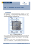
APPLICATION NOTE 314
ADC OF STM 300 / 31x / 330 – HOW TO MEASURE RAIL TO RAIL
Rail-to-Rail Sensor Applications using the STM 300, 31x and 330
© EnOcean | www.enocean.com | [email protected]
Christian Bach / Marian Hönsch | November 2011 | Page 1/ 8
APPLICATION NOTE 314
ADC OF STM 300 / 31x / 330 –
HOW TO MEASURE RAIL TO RAIL
Table of content
1. INTRODUCTION ............................................................................................................................................. 3
1.1.
REFERENCES................................................................................................................................................ 3
2. USE THE ONBOARD POT OF EVA 330 WITH STM 31X ......................................................................... 3
3. RAIL-TO-RAIL SENSOR APPLICATIONS WITH STM 31X ................................................................... 4
4. USING THE STANDARD STM 330 WITH EVA 330 ONBOARD POT..................................................... 4
5. RAIL-TO-RAIL SENSOR APPLICATIONS WITH STM 300 .................................................................... 5
5.1.
STEP BY STEP, RAIL-TO-RAIL SENSOR APPLICATION WITH STM 300 .......................................................... 6
© EnOcean | www.enocean.com | [email protected]
Christian Bach / Marian Hönsch | November 2011 | Page 2/ 8
APPLICATION NOTE 314
ADC OF STM 300 / 31x / 330 –
HOW TO MEASURE RAIL TO RAIL
1.
INTRODUCTION
STM 31x is a universal, customer configurable EnOcean module platform, for various sensor
applications. While STM 330 is configured as a calibrated 0 to 40 °C temperature sensor /
set point control and STM 320 as a magnetic (window) contact, STM 31x can be used more
flexible for different sensors like e.g. light sensor. Like the other above mentioned sensors,
the STM 31x can be configured using the EDK 31x (EVA 330 board, EOPX and DolphinStudio). In order to enable Rail-to-Rail measurements the STM 31x has a special firmware and
shall be used with an appropiate external adaption circuit shown in the following, (for more
details please also refer to STM 31x User Manual, §2.3.2 Analog and Digital Inputs / Analog
Input Mode and §3.2 Analog Measurement).
Note: The Dolphin chip inside STM 3xy cannot directly measure Rail-to-Rail (e.g. GND-toSWPWR), for more details please consult the Dolphin Core and specific STM 3xy user manuals [1], [5].
1.1. References
[1] Dolphin Core Description (http://www.enocean.com/knowledge-base/)
[2] EnOcean Software Download –
(http://www.enocean.com/en/download/)
[3] EnOcean Support –
(http://www.enocean.com/support/)
([email protected])
[4] STM 300 Product page –
(http://www.enocean.com/en/enocean_modules/stm-300/)
[5] STM 310 Product page –
(http://www.enocean.com/en/enocean_modules/stm-310/)
[6] STM 330 Product page –
(http://www.enocean.com/en/enocean_modules/stm-330/)
2.
USE THE ONBOARD POT OF EVA 330 WITH STM 31X
When you insert a STM 31x into the EVA 330 board, its ADIO3 and ADIO4 inputs will be “in
the air” (not connected on the EVA 330!) To measure correct the ADIO0 (connected to the
onboard pot), the module must however read the REFN and REFP levels which are expected
to be at ADIO3 and ADIO4. Without stable references here the measurement result will be
at random. To allow however the use of the pot (only for fast temperature change simulations) even without using an external additional external “shift” circuit, you can connect
these inputs to GND respectively SWPWR like shown below (red). Please note however that
in this case the delivered absolute values are not accurate (gain error) because the reference voltage is outside the ADC range and therefore cannot be measured accurately.
© EnOcean | www.enocean.com | [email protected]
Christian Bach / Marian Hönsch | November 2011 | Page 3/ 8
APPLICATION NOTE 314
ADC OF STM 300 / 31x / 330 –
HOW TO MEASURE RAIL TO RAIL
Figure 1 Rail To Rail with STM 31X on EVA 330
3.
RAIL-TO-RAIL SENSOR APPLICATIONS WITH STM 31X
To enable Rail-to-Rail measurements, two offset voltages REFN and REFP – which are within the measurement range of the Dolphin chip – have to be first generated by a simple appropiate voltage divider and for more accuracy buffered by voltage followers as shown below. This circuit shifts the supply voltage rails of the Sensor into the measurement range of
the ADC converter. The offset voltages are defined by the resistor divider R1, R2 and R3
with respect to the specified Dolphin chip range limitations. Resistors with a tolerance of
1% or less are hereby recommended. The sensor circuit (in its simplest form just a pot like
R4) must be designed to work and deliver voltages between REFN (0, about 4.2% of
SWPWR) and REFP (full scale, about 92.67% of SWPWR). Two additional STM 31x analog
inputs (ADIO3 and ADIO4) are therefore used now to read these references.
CODE ADC
0xFF
0x00
REFN
UADIO0
REFP
Figure 2 Reference design for STM 31X
4.
USING THE STANDARD STM 330 WITH EVA 330 ONBOARD POT.
If you use e.g. the STM 330 with the EVA 330 onboard pot, you will have the following circuit and (due to the Rail-to-Rail issue) errors near the rails, see also STM 330 User Manual
[4].
Note: Analogue inputs ADIO3/ADIO4 are not used on standard STM 330, means the default firmware in STM 330 does not perform measurements on ADIO3/ADIO4. In this case
you don’t need to do any modifications on the EVA 330 board, because the ADIO3 and
ADIO4 are not used (evaluated) in this case!
© EnOcean | www.enocean.com | [email protected]
Christian Bach / Marian Hönsch | November 2011 | Page 4/ 8
APPLICATION NOTE 314
ADC OF STM 300 / 31x / 330 –
HOW TO MEASURE RAIL TO RAIL
CodeADC
0xFF
Gain Error
ideal
real
Offset Error
0x00
0
1
UADC
URVDD
Figure 3 EVA 330 board with STM 330, circuit details and ADC output behavior.
5.
RAIL-TO-RAIL SENSOR APPLICATIONS WITH STM 300
When using STM 300 in an application with Rail To Rail you have to supply the reference
design with DVDD. The supply is controlled by the SCO (WXIDIO) pin. See the reference
design in Figure 4.
Figure 4 Reference design for STM 300
© EnOcean | www.enocean.com | [email protected]
Christian Bach / Marian Hönsch | November 2011 | Page 5/ 8
APPLICATION NOTE 314
ADC OF STM 300 / 31x / 330 –
HOW TO MEASURE RAIL TO RAIL
The reference design on Figure 4 is similar to the one described in Chapter 3 on Figure 2.
The difference is that STM 300 controls the circuit by the WXIDIO pin – SCO. Please see for
circuit description Chapter 3.
The standard STM 300 Firmware does not support Rail To Rail Measurements [4]. As
references for measurements the STM 300 Firmware takes:
RVDD - RF supply voltage regulator output (1.8 V)
RVSS - Ground connection for RF (0 V)
To enable Rail To Rail we have to measure the rail references on ADIO pins. STM 31x does
this by default, to see a working example see the STM 31X Source Code – STMSEN [2].
The STM 300 has no free ADIO pins to measure references during analog measurements.
You have to find a pin and free it in the firmware. As analog input only these ADIO pins are
available:
ADIO_0
ADIO_1
ADIO_2
ADIO_3
ADIO_4
Pins ADIO_0, ADIO_1 and ADIO_2 are used in STM 300 firmware as analog input channels
(0, 1, 2). Pins ADIO_3 and ADIO_4 are used in STM 300 firmware as digital input channels
(0, 1). To enable Rail to Rail you have to use the ADIO_3 and ADIO_4 for REFN and REFP
(recommended). This way you cannot use them any more as digital input channel 0 and 1.
By using a configuration pin as digital input you have to set the configuration values
in DolphinStudio and write them into the configuration area so the hardware settings will be
ignored. Otherwise if the configuration area does not hold any values the module will try to
read the hardware configuration pins, what will result into a non-defined state. Optionally
you can change the STM 300 firmware to take another default value, when the configuration area does not hold any set values.
5.1. Step by step, Rail-to-Rail Sensor Application with STM 300
To enable Rail To Rail with STM 300 you need to perform these steps:
1. Use the reference design as presented on Figure 4.
2. Change Source Code of STM 300 to use ADIO_3 and ADIO_4 as references during
analog measurements. Change the function - void MeasureAnalog() – located in
file measurement.c
© EnOcean | www.enocean.com | [email protected]
Christian Bach / Marian Hönsch | November 2011 | Page 6/ 8
APPLICATION NOTE 314
ADC OF STM 300 / 31x / 330 –
HOW TO MEASURE RAIL TO RAIL
3. Change the STM 300 pins configuration in DolphinStudio of ADIO_3 and ADIO_4
from digital input to analog input.
a. Open the stm300.dat file in DolphinStudio. (e.g.
.\SourceCode\Profiles\STM300.dat )
Change the pin configuration to analog input.
b. Save the profile (stm300.dat) file and generate the configuration files.
4. Compile and flash the Firmware into the module.
© EnOcean | www.enocean.com | [email protected]
Christian Bach / Marian Hönsch | November 2011 | Page 7/ 8
APPLICATION NOTE 314
ADC OF STM 300 / 31x / 330 –
HOW TO MEASURE RAIL TO RAIL
5. Configure the STM 300 with DolphinStudio. Set SCO pin as active LOW (if you are
using active HIGH convert polarity of SCO in reference design)
6. Set the Digital INPUT mask so DI0 and DI1 are not considered. For example see figure below, also other combinations are available.
7. Write the configurations to the module.
Disclaimer
The information provided in this document describes typical features of the EnOcean radio system and should not
be misunderstood as specified operating characteristics. No liability is assumed for errors and / or omissions. We
reserve the right to make changes without prior notice. For the latest documentation visit the EnOcean website at
www.enocean.com.
© EnOcean | www.enocean.com | [email protected]
Christian Bach / Marian Hönsch | November 2011 | Page 8/ 8