1
APPLICATION NOTE 501
SMART ACK – Bi-directional Thermostat with Display
1 Introduction
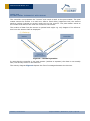
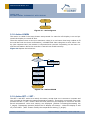
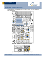
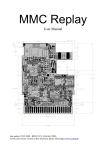
When EnOcean brought the first generation of battery less radio modules to the market
energy autarkic sensors - a combination of sensor, energy harvester and radio - were limited to uni-directional communication - only transmitting information. Now with the introduction of the new Dolphin platform this limitation could be extended to bi-directional
communicating autarkic sensors and even autarkic actors.
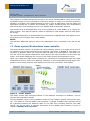
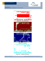
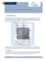
Figure 1 - Block diagram Dolphin Chip
Beside the new achievements on the hardware side the concept ―Smart Acknowledge‖ had
to be developed to enable an energy efficient way of handling bi-directional communication.
In the following also the term ―SMART ACK‖ is used as short form for ―Smart Acknowledge‖.
1.1 Purpose
This application note will explain the basics of the Smart Acknowledge concept and demonstrate it in a real world application. For a deeper understanding of the Smart Acknowledge
concept please see [1.] Smart Acknowledge specification, September 15, 20.
© EnOcean | www.enocean.com
Subject to modifications | Marian Hönsch | July 2011 | Page 1/ 54
APPLICATION NOTE 501
SMART ACK –
BI-DIRECTIONAL THERMOSTAT WITH DISPLAY
The purpose is to demonstrate the concept in an actual implementation using an as simple
as possible setup. It’s not intended as a reference design or ready to be used as production
software, providing a full implementation for such a type of application. But the demo and
description should be a tutorial and suitable for further enhancements and modifications
and should be a good starting point for own SMART ACK development projects.
The second focus of this application note is the operation of a LCD display in an energy autarkic system. This requires specific means to operate an LCD display with the least possible energy.
The selected application to demonstrate the combination of SMART ACK with display is a bidirectional room controller with a LCD display.
NOTE:
The software AN501SW which is part of this application note is provided on an ―AS-IS‖ basis.
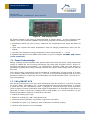
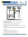
1.2 Demo system: Bi-directional room controller
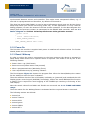
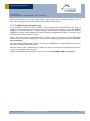
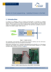
The demonstration shows a bi-directional communicating system of a simple room controller measuring the actual temperature and sending it as shown in Figure 2. The data is received by a gateway which e.g. would forward the data to a HVAC system. The HVAC system will return the target temperature value back to the room controller via the same gateway. This allows displaying the current in the HVAC system set temperature value.
Upon user interaction (SET button pressed) the command to increase/decrease the target
temperature value is send to the gateway. Resulting in an increased/decreased target temperature value being returned, and displayed on the room controller’s LCD display.
Figure 2 – Demo System
The demo system was developed based on the EnOcean developer kit EDK300. This kit
contains two evaluation boards.
First the EVA300, which is the evaluation board for the TCM300 module (transceiver module). This board is used as SMART ACK controller. Typically a SMART ACK controller would
be a gateway between the EnOcean radio on one side and a building network, like LON,
TCP-IP, etc. on the other. A detailed description of the SMART ACK controller is given in
chapter 3 SMART ACK controller.
© EnOcean | www.enocean.com
Subject to modifications | Marian Hönsch | July 2011 | Page 2/ 54
APPLICATION NOTE 501
SMART ACK –
BI-DIRECTIONAL THERMOSTAT WITH DISPLAY
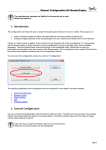
Figure 3 - Evaluation board EVA300
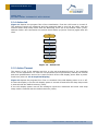
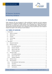
Secondly the EVA320, which is the evaluation board for the STM300 module (sensor module). This board is already equipped with
a solar cell as energy harvester
a Lithium capacitor as long term energy storage device
a temperature sensor
Figure 4 - Evaluation board EVA320
For the LCD display an additional (not part of the EDK300) PCB board was developed which
can be plugged onto the EVA320 prototyping area interface. Together those two boards act
as SMART ACK sensor demonstrating the room controller functionality.
© EnOcean | www.enocean.com
Subject to modifications | Marian Hönsch | July 2011 | Page 3/ 54
APPLICATION NOTE 501
SMART ACK –
BI-DIRECTIONAL THERMOSTAT WITH DISPLAY
Figure 5 - LCD Display board
As already stated is the focus on demonstrating a simple setup - a room controller with
display. The room controller (SMART ACK sensor) performs the following functionalities:
periodically wakes up (every 120s), measures the temperature and sends the data via
radio
upon user request the actual temperature and set (target) temperature value are dis-
played
the user can change the target temperature value using the SET + / - keys
A detailed description of the SMART ACK sensor is given in chapter 2 SMART ACK sensor
(room controller).
1.3 Smart Acknowledge
Energy autarkic sensors already used special means like ultra low power sleep (deep sleep
mode) to enable the use of energy harvesters like solar cells as power source. As the information provided by the sensors, e.g. temperature, humidity, CO2, was only send to a
permanent supplied and always listening receiver the sensor could simply send his data at
any time.
The overall energy consumption can be handled as a combination of long periods of virtually no activity (deep sleep mode with e.g. ~200 nA of current consumption) and very short
periods of waking up, measuring and transmitting the measured data (with ~25 mA of current consumption).
1.3.1 Why SMART ACK
Now there is the desire to not only send information from the sensor to a receiver, but also
to receive ―back‖ information. E.g. in the demonstration the actual temperature (T_actual)
is send and the set temperature value (T_target) is received from the room controller.
There is plenty of other information that might be desirable to be available to the sensor in
particular if it has a visual user interface like an LCD display. In a room controller e.g. the
following information might be of interest to the user:
Status of heating (On / Off)
Status of cooling (On / Off / Fan speed level)
Presents control (present, not present, night time reduction)
Windows are open (e.g. heating is turn off because a window is open)
Various other status or error messages
© EnOcean | www.enocean.com
Subject to modifications | Marian Hönsch | July 2011 | Page 4/ 54
APPLICATION NOTE 501
SMART ACK –
BI-DIRECTIONAL THERMOSTAT WITH DISPLAY
The main challenge in an energy autarkic system now is to household with it available
energy. As an enabled radio receiver is one of the biggest energy consumers (e.g. more
than 25mA) a concept to optimize the radio receiver on time to a minimum is necessary.
This concept has to address the following two main issues:
Receive mode consumes high amount of energy
Unknown delay times introduced through repeaters
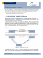
1.3.2 How does SMART ACK work (principle only)
Smart Acknowledge uses a mechanism where the sensor expects to receive a radio message from the controller in a predefined time slot. To achieve this the sensor sends a request (Reclaim) to signal to the controller that he is expecting to receive data and then
turns on its receiver for a short period of time.
In order to eliminate any latency e.g. introduced by repeaters (which would increase the
required receiver on-time and therefore energy consumption), the return data is delivered
beforehand to a so called mail box. This mail box needs to be located on a transceiver with
direct radio connection to the sensor. This transceiver can be the controller itself if no repeater is required or a repeater which has a direct radio connection to the sensor. The transceiver which administrates the mail box is called post master.
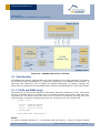
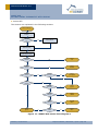
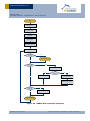
Figure 6a
Shows a setup where the sensor has direct radio contact to Controller.
Figure 6b
Shows a setup with a repeater acting as post master between the controller and the sensor,
and highlights the difference between the actual radio links and the logical connection.
Figure 6 - SMART ACK concept
For a SMART ACK system to work it is necessary to establish the relationship between the
sensor and the controller and to define who is acting as post master. This is done during
the so called learn process. Once the system is learned-in it can exchange the required data during normal operation.
© EnOcean | www.enocean.com
Subject to modifications | Marian Hönsch | July 2011 | Page 5/ 54
APPLICATION NOTE 501
SMART ACK –
BI-DIRECTIONAL THERMOSTAT WITH DISPLAY
1.3.3 Learn process (learn-in / learn-out)
With the learn process the relationship between a sensor and a controller is established.
The sensor tells the controller what type of data he provides (also see [3.] EnOcean
Equipment Profiles (EEP), V2.1, Jan. 2011) and what type of data he expects to receive.
SMART ACK supports two different types of learn modes called simple and advanced learn.
In simple learn mode the post master and therefore the mail box is located on the controller itself. In advanced learn mode also repeaters can act as post master. During the learn
process the transceiver best suited to act as post master will be selected.
Generally should the simple learn mode be used in all cases where the controller and sensor have a ―good enough‖ direct radio link. Only if that’s not the case then repeating is required and advanced mode has to be used. In advanced mode the radio devices have to be
installed in there final installation location to allow the proper selection of the most suitable
repeater as post master.
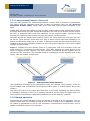
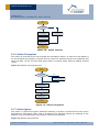
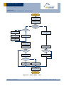
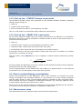
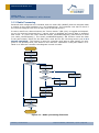
Figure 7 explains how the actually learn-in is performed. First the controller is set into
learn mode (e.g. by pressing a Learn button). Then after pressing the Learn button on the
sensor it triggers a learn request. The learn request is forwarded by the repeater and received from the controller. The controller sends a confirmation via the repeater back to the
sensor. Now the system is learned-in.
Figure 7 - Learn process (with repeater)
The information exchange of the confirmation (from the repeater to the sensor) is also using the SMART ACK mechanisms including the reclaim (there is a data reclaim and a learn
reclaim).
The learn-out is done in the same way than learn-in by simply repeating the learn process.
A ―repeated‖ attempt to learn-in an already learned-in sensor learns-out again and viceversa. Learn-out deletes the relationship between the sensor and the controller.
1.3.4 Normal operation
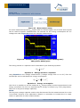
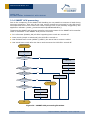
Prerequisite for normal operation is that the sensor is learned-in at the controller. The exchange of data with one repeater acting as post master is depictured in Figure 8. The sensor wakes up periodically or due to user interaction, measures and sends its data. The repeater forwards the data to the controller.
© EnOcean | www.enocean.com
Subject to modifications | Marian Hönsch | July 2011 | Page 6/ 54
APPLICATION NOTE 501
SMART ACK –
BI-DIRECTIONAL THERMOSTAT WITH DISPLAY
The controller now prepares the ―answer‖ and sends it back to the post master. The post
master stores the answer in a mail box. After a fixed delay (response time) the sensors
sends a reclaim (request to receive) and turns on the receiver. The post master reacts to
the reclaim and delivers the mail box content to the sensor.
The reclaim of data from the sensor is optional and might e.g. only happen if the information from the answer shall be displayed.
Figure 8 – Normal operation
In case that the controller is the post master (without a repeater) the data is not actually
sent, but directly stored in the mail box.
The activity diagram Figure 9 depicts the flow of messages between the devices.
© EnOcean | www.enocean.com
Subject to modifications | Marian Hönsch | July 2011 | Page 7/ 54
APPLICATION NOTE 501
SMART ACK –
BI-DIRECTIONAL THERMOSTAT WITH DISPLAY
sd Smart ACK w ith Repeater - Operating
Energy autarkic
sensor
Repeater
Controller
{Is Post Master}
Data()
Data Reply()
Save Acknowledge
to MailBox()
opt data ack
[sensor want ack]
Data Reclaim()
Data Acknowledge()
Figure 9 – Normal operation activity
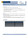
1.4 Demo Limitations
The demonstration has several limitations mainly to reduce the complexity and therefore
increase the ease of understanding.
The SMART ACK controller can only learn-in one SMART ACK sensor
The SMART ACK sensor only supports to be learned-in by one controller
Only simple SMART ACK learn mode is enabled (no repeater)
A standard LCD display was user (rather than a application optimized one, e.g. requires
more energy)
Energy management on EVA320 evaluation board not optimized to used LCD display
constraints (e.g. LCD display is only operating if long term storage voltage has reached
at least 3V)
1.5 References
Further details can be found in the following documentation
[1.]
Smart Acknowledge specification, September 15, 2010
[2.]
DolphinAPI user manual, EO3000I_API.chm, 2.2.1.0
[3.]
EnOcean Equipment Profiles (EEP), V2.1, Jan. 20, 2011
© EnOcean | www.enocean.com
Subject to modifications | Marian Hönsch | July 2011 | Page 8/ 54
APPLICATION NOTE 501
SMART ACK –
BI-DIRECTIONAL THERMOSTAT WITH DISPLAY
[4.]
Application note AN3415
(www.freescale.com)
-
OLED
Display
Driver
for
the
HCS08
Family
[5.]
Sitronix ST7565R - 65 x 132 Dot Matrix LCD Controller/Driver datasheet, V1.5,
2006/03/10
[6.]
DOGM GRAFIK SERIE - 132x32 PIXEL datasheet, Stand 1.2009
[7.]
Schematics EVA300-3
[8.]
Schematics EVA320-2
[9.]
Schematics LCD board (8.1 Schematics)
[10.]
STM300 User Manual
[11.]
STM300 Data Sheet
[12.]
TCM300 User Manual
[13.]
TCM300 Data Sheet
Useful web sites:
[14.]
EnOcean website http://www.enocean.com
[15.]
EnOcean Alliance website http://www.enocean-alliance.org
[16.]
Wikipedia website http://www.wikipedia.org/
[17.]
Electronic Assembly website http://www.lcd-module.de
[18.]
Sitronix website http://www.sitronix.com.tw/about.htm
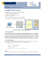
2 SMART ACK sensor (room controller)
The SMART ACK sensor has the following features:
STM300 module with Dolphin chip
Solar cell as energy harvester
Energy management to control charging of Long Term Storage and Vdd capacitor
Charge gauge to measure Long Term Storage voltage
Temperature sensor to measure the room temperature (T_actual)
Buttons for user control (Set+, Set-, Learn, Occupation)
LCD display with Power Control and Interface circuitry
© EnOcean | www.enocean.com
Subject to modifications | Marian Hönsch | July 2011 | Page 9/ 54
APPLICATION NOTE 501
SMART ACK –
BI-DIRECTIONAL THERMOSTAT WITH DISPLAY
Figure 10 - SMART ACK sensor overview
2.1 Functionality
The SMART ACK sensor demonstrates the basic operations of a room controller by measuring the actual room temperature (T_actual) and sending it to the SMART ACK controller. In
case the user expects to see or modify the target temperature (T_target) settings, the
value will be requested from the SMART ACK controller and displayed in on the LCD display.
2.1.1 FLASH and RAM0 usage
The behaviour of the sensor depends if the sensor has been learned-in or not. The sensor
stores a successful learn-in (or learn-out) in its FLASH memory and remains valid even during power off. The sensor stores the time it has to wait for an answer, the mail box index
(used if sensor is learned multiple times into one controller) and the controller ID.
typedef struct
{
uint16 u16ResponseTime;
uint8
u8MailboxIndex;
uint32 u32ControllerId;
} FLASH_DATA;
FLASH_DATA code u8gFlashData;
NOTE:
To avoid undefined behaviour it is important that the learn-in / learn-out status remains
© EnOcean | www.enocean.com
Subject to modifications | Marian Hönsch | July 2011 | Page 10/ 54
APPLICATION NOTE 501
SMART ACK –
BI-DIRECTIONAL THERMOSTAT WITH DISPLAY
synchronized between sensor and controller. This might cause unexpected effects, e.g. if
one side is reprogrammed and therefore, by default not learned-in.
The ultra low power RAM (RAM0) is used to store information which must not be lost during
deep sleep mode (but can be lost during power off). In this application it is only used for
debug purposes, to store the status of the last reclaim operation. In the data telegram this
status (from the previous reclaim) is transmitted to the SMART ACK controller. Also see 2.2
Radio Telegram and Fehler! Verweisquelle konnte nicht gefunden werden..
typedef struct
{
uint8 u8ReclaimCounter;
} RAM0_SHADOW_STRUCT;
RAM0_SHADOW_STRUCT xdata ram0;
2.1.2 Power On
The first time the module is supplied with power it initializes all relevant values. For further
details please see next section.
2.1.3 Reset / Wakeup
In order to reduce the energy consumption to the bare minimum the device is operated in
Deep Sleep mode whenever no specific action is required. This mode is left by one of the
following reasons:
Power down->up (VDD Reset)
Reset occurred (Reset button was pressed)
After a programmed time (Watchdog Timer)
User requested activity by pressing a button
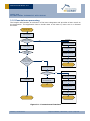
The flow diagram Figure 11 depicts the program flow. After the Reset/Wakeup the reason
for the wakeup is store for later evaluation.
Then the software checks if the LCD Display is already on (powered) and initialized the LCD
Display power control signal (WXIDIO) accordingly, before the actual EO3000I Init function
is called. This is required to avoid toggling of the WXIDIO pin resulting in flickering of the
LCD Display.
Next the stored values from RAM0 and FLASH are recovered see 2.1.1 FLASH and RAM0
usage.
Then the reason for the Wakeup/Reset is evaluated and the required Action is executed.
The following actions are defined:
Action Init
Action Timeout
Action OCCU
Action Ignore
Action LEARN
Action SET+
© EnOcean | www.enocean.com
Subject to modifications | Marian Hönsch | July 2011 | Page 11/ 54
APPLICATION NOTE 501
SMART ACK –
BI-DIRECTIONAL THERMOSTAT WITH DISPLAY
Action SET-
The Actions are explained in the following sections.
Reset / Wake-up
Store Reset / Wake-up
Reason
Is LCD Display
on?
Set WXIDIO
yes
no
EO3000I Init
Read RAM0 values
Read FLASH values
PIN or VDD
Reset?
yes
Action
Init
yes
Action
Timeout
no
Watchdog
Reset?
no
WAKE0
Reset?
Button
Pressed?
yes
Action
OCCUpation
yes
no
no
WAKE1
Reset?
yes
Button
Pressed?
no
Action
Ignore
yes
Action
LEARN
yes
ACTION
SET+
yes
Action
SET-
yes
LEARN
Button?
no
no
SET+
Button?
no
Action
Ignore
no
SETButton
Figure 11 - SMART ACK sensor flow diagram 1
© EnOcean | www.enocean.com
Subject to modifications | Marian Hönsch | July 2011 | Page 12/ 54
APPLICATION NOTE 501
SMART ACK –
BI-DIRECTIONAL THERMOSTAT WITH DISPLAY
2.1.4 Action Init
Figure 12 depicts the program flow of the initialization. First the LCD Power is turned of.
The analogue inputs are measured and the measured data is send via the radio. Last the
module enters deep sleep mode with the Watchdog Timer set to the default value (120s).
Without further user interaction the module would wake up (Action Timeout) again after the
120s.
Action
Init
LCD Power Off
Measure
Analog Signals
Send Data Telegram
Set Deep Sleep Timer
Default value
Deep Sleep
Figure 12 - Action Init
2.1.5 Action Timeout
This action is call if the wakeup was due to the pre-programmed time in the watchdog
timer. In this application it is used for two purposes first to periodically wakeup the module
and send updated data. Second it is used to switch off the LCD display power after a predefined time (also see 2.3.3 Graphical display)
Figure 13 depicts the program flow. First it is checked if the LCD display power is on or off.
In case the display is on the LCD display power is turned off and then the deep sleep mode
is entered with the default timeout (120s).
If the LCD display power was off the analogue inputs are measured and send. And deep
sleep mode is entered with the default timeout (120s).
© EnOcean | www.enocean.com
Subject to modifications | Marian Hönsch | July 2011 | Page 13/ 54
APPLICATION NOTE 501
SMART ACK –
BI-DIRECTIONAL THERMOSTAT WITH DISPLAY
Action
Timeout
Is LCD display
On?
yes
no
Measure
Analog Signals
Turn LCD display off
Send Data Telegram
Set Deep Sleep Timer
Default value
Deep Sleep
Figure 13 - Action Timeout
2.1.6 Action Occupation
This action is executed if the user presses the Occupation button. In case the LCD display is
on and powered the display is turned off first. Next the analogue inputs are measured and
send via radio. At the end the deep sleep mode is entered again with the default timeout
(120s).
Figure 14 depicts the program flow.
Action
OCCU
Is LCD display
On?
yes
Turn LCD display off
no
Measure
Analog Signals
Send Data Telegram
Set Deep Sleep Timer
Default value
Deep Sleep
Figure 14 - Action Occupation
2.1.7 Action Ignore
This action is required to ignore wakeups meaning no action is performed but the device
goes back to deep sleep mode. This is needed for the wakeups caused by releasing of the
buttons (only the asserting of the buttons is performing actions).
Figure 15 depicts the behaviour.
© EnOcean | www.enocean.com
Subject to modifications | Marian Hönsch | July 2011 | Page 14/ 54
APPLICATION NOTE 501
SMART ACK –
BI-DIRECTIONAL THERMOSTAT WITH DISPLAY
Action
Ignore
Deep Sleep
Figure 15 - Action Ignore
2.1.8 Action LEARN
This action is called if the Learn button was pressed. In case the LCD display is on and powered the display is turned off first.
Then the response time is set to its maximum value (it is not known how long it takes to fill
the mail box with the learn confirmation), a SMART ACK learn telegram is send. After a delay (the response time) the answer is requested and received. Depending on the learn result the information about the controller is stored into FLASH memory.
Figure 16 depicts the behaviour.
Action
LEARN
Is LCD display
On?
yes
Turn LCD display off
no
Set default (max.)
Response Time
Send SMACK Learn
Telegram
SMACK Learn Reclaim
Set Deep Sleep Timer
Default value
Deep Sleep
Figure 16 - Action LEARN
2.1.9 Action SET + / SET The SET+ and SET- action are mainly the same, except that one is meant to increase and
one is meant to decrease the target temperature setting. This action is executed if the user
presses the SET+ / SET- button. After the first press only the displays is turned on and the
actual temperature value and setting are displayed (without increasing/decreasing the
T_target). Subsequent presses (before the 5s display off timeout - whilst the display is still
on) of the SET+ / SET- button modify the temperature setting (T_target).
© EnOcean | www.enocean.com
Subject to modifications | Marian Hönsch | July 2011 | Page 15/ 54
APPLICATION NOTE 501
SMART ACK –
BI-DIRECTIONAL THERMOSTAT WITH DISPLAY
Figure 17 depicts the program flow (without the displaying of debug information - also see
Figure 21). First the analogue inputs are measured and the actual temperature (T_actual)
and the voltage of the long term storage device are calculated. Then the software evaluates
if there is enough energy available to operate the LCD display based on the voltage of the
long term storage device (also see 2.3.5 Handling of LCD display supply range).
If there is not a sufficient amount of energy available, then the LCD display is turned
off, and the data is send. Depending on if a SMART ACK controller is known a data reclaim
is performed. At the end the deep sleep mode is entered. On the radio side this is basically
the same behaviour than with display.
If there is sufficient energy available, then first it is distinguished if the display is already on or off (first press or subsequent press). In case it is off the LCD display power is
turned on, the display is initialized and the static display content (see Figure 21) is written. In case the display was already on those steps are ceased for energy optimization,
only the watchdog timer is reset (display stays on for 5s – from now on).
Next the dynamic display content (see Figure 21) is written and the data is send. Depending on if a SMART ACK controller is known a data reclaim is performed. If the data reclaim
was successfully (data received from SMART ACK controller) then the target temperature
(T_target) is displayed otherwise a placeholder (‖--.-―) is displayed. Finally deep sleep
mode is entered with the display timeout (5s). During Deep Sleep the display remains on
displaying the data written before. If there is no further user activity the display is turned
of after the display timeout (5s) also see 2.1.5 Action Timeout.
© EnOcean | www.enocean.com
Subject to modifications | Marian Hönsch | July 2011 | Page 16/ 54
APPLICATION NOTE 501
SMART ACK –
BI-DIRECTIONAL THERMOSTAT WITH DISPLAY
Action
SET+ / SET-
Measure
Analog Signals
Calculate Tactual and
V_LT
yes
no
Enough
Energy avalaible to
operate LCD
display?
Is LCD display
On?
Turn LCD display on
Turn LCD display off
yes
LCD Init
no
Clear Watchdog
Write static LCD
content
Write dynamic LCD
content (Tactual)
no
Send Data Telegram
Send Data Telegram
SMACK
Controller
known?
SMACK
Controller
known?
yes
yes
Perform
SMACK Data Reclaim
Perform
SMACK Data Reclaim
Data received
no
no
yes
Calculate and display
Ttarget
display Ttarget = „-.—„
Set Deep Sleep Timer
Display Timeout value
Deep Sleep
Figure 17 - Action SET+ / SET-
© EnOcean | www.enocean.com
Subject to modifications | Marian Hönsch | July 2011 | Page 17/ 54
APPLICATION NOTE 501
SMART ACK –
BI-DIRECTIONAL THERMOSTAT WITH DISPLAY
2.2 Radio Telegram (Data Telegram)
During normal operation the room controller sends the following information:
Actual temperature value (T_actual)
Command to controller (eCmd) none, increase/decrease T_target
And the following additional (debug) information:
Voltage level of long term energy storage device U_longterm
Reason for the wakeup (eAction)
Status of last SMART ACK activity (e.g. Idle, no controller known, number of SMART ACK
requests)
NOTE:
The SMART ACK telegrams are not described here! Please see [1.] Smart Acknowledge
specification, September 15, 20 for further information. A detailed description of the received data telegram sent by the controller can be found in 3.2 Radio Telegram.
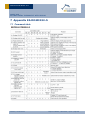
Above information is packed into a 4BS radio telegram in the following way
4BS Telegram
Choice
1byte
Data3..0 SrcId Status Checksum
4byte
4byte 1byte
1byte
Table 1 - 4BS radio telegram
Choice
4BS telegram
Data3.Bit[7..4]
Reason for the wakeup (enum eAction)
Init (after Power On or Reset)
0
Ignore
1
Timeout
2
Fehler! Verweisquelle konnte nicht gefunden werden.
Button Occupation pressed (Wake 0)
3
Button Learn pressed (Wake 1)
4
Button Set+ pressed
5
Button Set- pressed
6
Data3.Bit[3..0]
Command
No command
Increment T_target
Decrement T_target
Data2
Data1
© EnOcean | www.enocean.com
Fehler! Verweisquelle konnte nicht gefunden werden.
0xA5
0
1
2
Voltage of long term storage device
U_longterm = (N * 2 * 1,8 / 255)V
Temperature value
0..40°C
N = 0..255
0xFF..0x00 (linear)
Subject to modifications | Marian Hönsch | July 2011 | Page 18/ 54
APPLICATION NOTE 501
SMART ACK –
BI-DIRECTIONAL THERMOSTAT WITH DISPLAY
Data0.Bit[7..4]
Status of previous SMART ACK activity
Not used
Data received after first data reclaim
Data received after second data reclaim
Data received after third data reclaim
No data received after 3 tries
Signal (e.g. MB empty)
No SMART ACK controller known
Initial state
Data0.Bit[3..0]
Bit3 is set to 1 to be compliant with
EnOcean Equipment Profiles (EEP)
Bit3 = 0 teach-in telegram
Bit3 = 1 data telegram
SrcID
32bit ID of telegram source
0x0000_0001..0xFFFF_FFFF
Fehler! Verweisquelle konnte nicht gefunden werden.
Reserved
0x0000_0000
Status
Status information
Fehler!
field Verweisquelle konnte nicht gefunden werden.
0x00
Checksum
Checksum of theFehler!
radio telegram
Verweisquelle konnte nicht Calculated
gefunden werden.
checksum
2.3 Display
The display selected for this demonstration is the EA DOGM 132 (also see [6.] DOGM
GRAFIK SERIE - 132x32 PIXEL datasheet, Stand 1.2009). It’s a graphical LCD display
with 132x32 pixels. This display was chosen for it’s low power consumption (typically
140uA) and relative wide operating voltage range (2.4V..3.3V). Also the easy availability
e.g. for end customers, was taken into account.
This display uses the ST7565R LCD display segment driver IC (also see [5.] Sitronix
ST7565R - 65 x 132 Dot Matrix LCD Controller/Driver datasheet, V1.5,
2006/03/10). The driver IC is integrated onto the LCD display glass (COG – Chip On
Glass).
The LCD display has the following features:
low current consumption
Serial interface (SPI)
wide operating voltage range
1.8V interface voltage
readable without background lighting (reflective)
easy available (easy to buy)
In real applications rather a segmented LCD would be used with Icon type of display. Today
available display drivers for such LCD display are available for wide operating voltage range
and require less than a third of the ST7565R driver current. Additionally will the energy
(time) to update the display be significantly lower compared the used graphic display (e.g.
less then 100 segments compared to 4228 pixels).
© EnOcean | www.enocean.com
Subject to modifications | Marian Hönsch | July 2011 | Page 19/ 54
0
1
2
3
4
5
E
F
APPLICATION NOTE 501
SMART ACK –
BI-DIRECTIONAL THERMOSTAT WITH DISPLAY
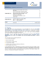
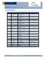
2.3.1 Hardware interface
The LCD display uses a SPI like interface for the display commands and data. It only uses
unidirectional data transfer from the STM300 (host) to the display. The SPI uses three signals (unidirectional) and one additional signal to distinguish between display data and
commands send to the display controller
Signal
Direction
CS
CLK
SI
A0
RESET
VDD
VDD2
VSS
In
In
In
In
In
Description
Chip select signal (low active)
Serial clock
Serial in data
Command / data select
Reset (low active)
Analog supply
IO supply
Ground
Table 2- LCD Display signals
Figure 18 - LCD display interface
There are 2 supply pins one for the ―analog‖ display supply (VDD) and one for digital interface (VDD2 = IO VDD). The operating range of the display supply VDD is from 2,4V..3,3V.
The IO supply range is from 1,8V..3,3V.
The reset signal (low active) needs to be externally connected (no internal pull up).
© EnOcean | www.enocean.com
Subject to modifications | Marian Hönsch | July 2011 | Page 20/ 54
APPLICATION NOTE 501
SMART ACK –
BI-DIRECTIONAL THERMOSTAT WITH DISPLAY
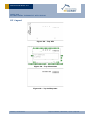
2.3.2 SPI Protocol
The SPI interface can use a clock up to 20MHz. The CS signal has to be active (low) before
data is transferred. The clock signal (SCL) is high when idle, the data (SI) has to be applied
with the falling edge of the clock signal and is sampled with the rising edge of the clock
signal as shown in the figure below.
Figure 19 - SPI Protocol
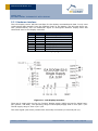
2.3.3 Graphical display
One other aspect of the display is that is a graphical display. This means that any information to be displayed has to be done by turning on/off single pixels. However there are certain restrictions how the single pixels can be accessed:
The pixels are accessed via the SPI interface on a byte level (write granularity). This
means that at least 8 pixels are written with one SPI transfer
The SPI access is only unidirectional (no read back)
The display is organized in 4 pages with 132 bytes (pixels) each (see Figure 20).
This means that it is practically not possible to update a single pixel. A method of readmodify-write to access single pixels would require, due to the unidirectional SPI interface,
to store a copy of the whole display content in the hosts (STM300) RAM memory.
Figure 20 - EA DOGM132 display memory mapping
For this demonstration the display is used like an alpha-numeric display using the 4 pages
as lines of text in combination with a soft font (font.h/font.c) which is linked together with
the Keil project. The implementation is using 2 fonts
extern code char FONT5X7[][5];
extern code char FONT8X15[][2][8];
This allows writing of either single height (5x7pixel) characters in one page or double
height (8x15pixel) character using 2 pages.
© EnOcean | www.enocean.com
Subject to modifications | Marian Hönsch | July 2011 | Page 21/ 54
APPLICATION NOTE 501
SMART ACK –
BI-DIRECTIONAL THERMOSTAT WITH DISPLAY
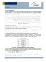
The display content can be classified into 3 different types:
Static content (marked with light blue background)
only written once during a display on-off cycle
Dynamic content (marked with yellow background)
updated every time e.g. a SET button is pressed
Debug content (marked with orange background)
Figure 21 depicts the LCD display content with the different content classes and the usage
of the 2 different sized fonts.
Figure 21 - Display content
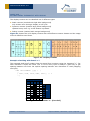
Example of writing with Font 5 x 7
This example shall briefly explain how the actual font is written using the character ―1‖. For
each character 5 bytes are used. The 7th bit of every byte is always 0 (pixel off) to get
spacing between two lines. No explicit spacing between two characters is used (skipping
one byte).
code char FONT5X7 [][5] = {
….
{ 0x00, 0x42, 0x7F, 0x40, 0x00 }, // 1
….}
Byte
0
1
2
3
4
0
1
2
3
4
5
6
7
Bit
x00 x42 x7F x40 x00
Figure 22 - Character "1" (Font 5x7)
© EnOcean | www.enocean.com
Subject to modifications | Marian Hönsch | July 2011 | Page 22/ 54
APPLICATION NOTE 501
SMART ACK –
BI-DIRECTIONAL THERMOSTAT WITH DISPLAY
Example of writing with Font 8 x 15
This example shall briefly explain how the actual font is written using the character ―1‖. For
each character 2 times 8 bytes are used (written into two pages). The 7th bit of the byte
8..15 is always 0 (pixel off) to get spacing between two lines. No explicit spacing between
two characters is used (skipping one byte).
code char FONT8X15 [][2][8] = {
….
0x00,0x04,0x06,0xFF,0xFF,0x00,0x00,0x00,
0x00,0x08,0x08,0x0F,0x0F,0x08,0x08,0x00 , // 1
….}
Byte
0
1
2
3
4
5
6
7
0
1
2
3
4
5
6
7
Bit
0
1
2
3
4
5
6
7
Bit
x00 x04 x06 xFF xFF x00 x00 x00
8
9 10 11 12 13 14 15
x00 x08 x08 x0F x0F x08 x08 x00
Figure 23 - Character "1" (Font 5x7)
NOTE:
Not all characters are implemented. Only the characters according to ASCII coding from 32
(Space) to 126 (―~‖) are implemented, plus the character ―°‖ at 127 (none ASCII) to display ―degree‖. For details please see Font.h/.c source code.
2.3.4 Energy efficient LCD display operation (Challenges)
To operate the LCD display in an energy autarkic system special care needs to be taken to
operate as energy efficient as possible. This chapter describes the key means used in this
demonstrator.
The following challenges had to be solved:
How to implement the electrical interface
© EnOcean | www.enocean.com
Subject to modifications | Marian Hönsch | July 2011 | Page 23/ 54
APPLICATION NOTE 501
SMART ACK –
BI-DIRECTIONAL THERMOSTAT WITH DISPLAY
How to energy optimize communication (minimize time)
How to handle supply voltage range (see 2.3.5 Handling of LCD display supply
range)
Electrical Interface
After a user interaction die display has to be turned on, display the necessary information
and remain on for e.g. 5s without a need to change the displayed information. After 5s
without further user interaction the display can be turned off.
The best way to implement this functionality is to switch the display power supply controlled by software and to use a low power mode during the 5s of display on (without any
further software activity). The lowest current consumption can be achieved using Deep
Sleep mode during this 5s waiting time. In Deep Sleep mode only the ultra low power
blocks (UVDD supplied) remain powered.
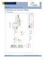
As drawn in 8.1 Schematics the WXIDIO GPIO is used to control the display power supply
(VDD2) using the transistors Q1 and Q2. The WXIDIO keeps its output even during Deep
Sleep mode. The IO supply of the display is directly connected to the WXIDIO. This is reducing the circuitry for one additional transistor switching the UVDD -> VDD connection.
Also the digital interface (SPI) needs to taken special care off to avoid parasitic current in
particular during display off state. This means that during display on in Deep Sleep mode
and during display off in Deep Sleep mode the digital interface pin shall be at 0V (Off).
The RST signal must remain high (active low) during the whole time of its operation, that’s
why it is directly connected to VDD via a 470k resistor. The A0, SCL and SI signals can be
directly connected to the GPIOs of the STM300 module. The CS (low active) needs to be
high also during the 5s of display on without update. That’s why the CS is not directly connected but inverted using the transistor Q3. The inverting of the CS signal generation is
done by software.
Display communication
The display is controlled via SPI data communication. To communicate with the display the
STM300 needs to be in CPU mode which requires significant amount of current. On the other hand using a graphical display requires a lot of data to be exchanged with the display.
E.g. to clear the display (write all pixels ―off‖) requires 132 x 4 bytes = 512 bytes to be
send.
An explicit clear however is not necessary if e.g. text is written anyway to the same area.
In the demonstration all the display areas which contain static data or where the dynamic
data is already available are written to (also see Figure 21). Then the areas which will be
written to later on are selectively cleared before the actual display on command is send.
Like this the double writing (clear plus data) is avoided.
A second optimization can be achieved by selectively updating display content. For this the
display content was split into static and dynamic areas (also see Figure 21). The dynamic
areas are the only ones updated for a subsequent display changes and the static content
remains unchanged. E.g. if the SET button was pressed again whilst the display is already
on and displaying information, then only the dynamic content gets updated.
Using above methods it was possible to reduce the display communication related energy
consumption by more than 50%!!
Another straight forward approach is simply increasing the SPI frequency and avoiding toggling of the CS signal e.g. after every sent byte. Increasing the SPI frequency from 500 kHz
to 2 MHz for instance saved about 10% energy.
© EnOcean | www.enocean.com
Subject to modifications | Marian Hönsch | July 2011 | Page 24/ 54
APPLICATION NOTE 501
SMART ACK –
BI-DIRECTIONAL THERMOSTAT WITH DISPLAY
2.3.5 Handling of LCD display supply range (used method)
One of the limitations of the used LCD display is the required minimum analog supply VDD2
which has to be above 2.4V. Below this voltage the display shows flickering and other unwanted behavior. For this reason the display is only activated if the stored energy (voltage)
is sufficient to turn the display on (also see 2.1.9 Action SET + / SET -). The criteria used
for this is the measured voltage on the long term storage capacitor CLT.
Figure 24 - Supply Principle
Figure 24 shows the relevant principle circuitry. If the voltage on C VDD is decreasing due to
the current consumption of the module the diode will start to become conducting. The voltage difference between the two capacitors will be depending on the forward voltage U F of
the diode and the internal source resistance of the long term capacitor C LT.
Figure 25 - Internal resistance of CLT
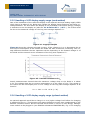
Actual measurements showed that the maximum voltage drop on the diode is in about
0.3V. The voltage drop due to current consumption is in the range of 0.3V. This results in
the criteria for the LCD display turn on of a voltage on the long term storage capacitor of at
least 3V.
UCLT > 2.4V + 0.3V +0.3V (> 3V)
2.3.6 Handling of LCD display supply range (optional method)
An optional approach would be to charge CVDD to a higher voltage level before the charging
is switched to the CLT. This however will require different circuitry than implemented on the
EVA320 evaluation board. But the EVA320 would allow to use of an own Energy Management module to be plugged in (see EVA320 schematics ENOCEAN-EM). E.g. if the charging
© EnOcean | www.enocean.com
Subject to modifications | Marian Hönsch | July 2011 | Page 25/ 54
APPLICATION NOTE 501
SMART ACK –
BI-DIRECTIONAL THERMOSTAT WITH DISPLAY
would be done up to 4,5V (VLIMIT), are 470uF CVDD would be able to provide about 3.4mWs
(discharge down to 2,4V).
See Equation 2 with C=470uF, U1=4,5V, U2=2,4V
The energy required to initially turn on the LCD display (including all other activities, measurements, radio, etc.) is about ~3.2mWs.
Using this different approach would e.g. significantly improve the initial startup time (out
off the box –> till operating) in case of are ―empty‖ long term storage device.
2.3.7 Start-up time – dimensioning of CVDD
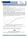
One of the key features of the energy management is the intelligent charging of the ―operation capacitor‖ CVDD and the capacitor for the long term storage C LT. Due to the different
capacitance of those two capacitors (e.g. 250mF vs. 470uF) the CVDD needs to be charged
first to achieve are quick initial ready for operation time. Once the CVDD has reached a defined level (VON ~2,45V) the CLT is charged. The CLT is connected to the CVDD via a diode
(also see Figure 24 - Supply Principle). So once the voltage on the CLT has reached the
same level (plus one diode forward voltage) both capacitors are charged.
Figure 26 - Charging of VDD and Long Term Storage Capacitors
For the CVDD capacitor we have two concurrent targets:
to have a small capacitance for a fast charging and a quick ―out-off-the-box‖ start-up
time
to have enough energy stored to handle application energy requirements
The equation to dimension the capacitor can be derived from Equation 2
C
2W
U12 U 22
Equation 1 – Dimensioning C_VDD capacitor
With W as required energy, U1 voltage of the capacitor when the energy is consumed (e.g.
VON ~2,4V), U2 minimum operating voltage (e.g. VOFF ~1,8V).
© EnOcean | www.enocean.com
Subject to modifications | Marian Hönsch | July 2011 | Page 26/ 54
APPLICATION NOTE 501
SMART ACK –
BI-DIRECTIONAL THERMOSTAT WITH DISPLAY
2.3.8 Start-up time - STM300 Firmware requirements
The EVA320 evaluation board was optimized for the standard STM300 firmware, basically
having enough energy to:
wake up
measure and sense inputs
and to transmit the data (3 sub telegrams) via radio.
The CVDD with 470uF on the EVA320 easily fulfils this requirements.
2.3.9 Start-up time - SMART ACK requirements
On the other hand for SMART ACK the energy requirements are different to the STM300
Firmware. First of all it will be desirable to at least be able to learn-in the sensor which requires the following steps:
wake up
transmit a learn request (3 sub telegrams) the data via radio
transmit a learn reclaim and receive the learn reply data
evaluate the learn result and store information into FLASH memory
A successful learn-in this will require about 1mWs (best case only one reclaim) to 1,9mWs
(worst case 3 reclaims) of energy.
This will result (using Equation 1) into a capacitor of about 1500uF without any safety
margin.
C
2 1,9mWs
~ 1500uF
(2,4V ) 2 (1,8V ) 2
For this purpose an additional (to the CVDD 470uF on the evaluation board) 1000uF capacitor
was placed onto the LCD display board.
For the implementation of the SMART ACK with display it is assumed that it is not required
to be able to turn on the display in this short start-up time.
2.4 How to evaluate Energy consumptions
During the development of this application note it was necessary to quantify and verify
energy consumption and therefore measure it. The intention is to verify energy household
and see where energy is used. The described method is intended for easy and quick qualitative analyses and not so suitable for quantitative analyses. E.g. does the capacitor (used
in this method) typically have tolerances of 20%!!
As this is one of the standard tasks in developing ultra-low power applications one possibility to measure the energy consumption is explained in detail here.
2.4.1 Measurement setup
The measurements were preformed with a multi channel oscilloscope.
© EnOcean | www.enocean.com
Subject to modifications | Marian Hönsch | July 2011 | Page 27/ 54
APPLICATION NOTE 501
SMART ACK –
BI-DIRECTIONAL THERMOSTAT WITH DISPLAY
Figure 27 - Measurement setup
For most measurements the DVDD signal could be used as trigger, but of cause other signals
can be used for specific measurements. As indicator for the energy consumption the VDD
voltage was used. Figure 28 shows an example measurement.
Figure 28 - Example "Occu" (measure, send 3 Subtelegrams)
VDD-yellow, DVDD-green
The energy stored in a capacitor can be described by the following equation:
W
1
C U2
2
Equation 2 – Energy stored in a capacitor
Using Equation 2 the voltage measurement (―voltage change from U1 to U2‖) from the
oscilloscope can be calculated into energy consumption:
W
1
C U 12
2
U 22
Equation 3 – Energy consumption
Like this it is possible to use the measured VDD change (delta) as direct proportional to the
energy consumed. For this it is required that no energy is inserted (e.g. from programmer,
solar cell or long term storage capacitor).
NOTE:
The long term storage capacitor needs to be disconnected for this measurements due to the
―none-linear‖ behavior of its capacitance. Maybe it is necessary to increase the CVDD capacitance in particular for those measurements.
© EnOcean | www.enocean.com
Subject to modifications | Marian Hönsch | July 2011 | Page 28/ 54
APPLICATION NOTE 501
SMART ACK –
BI-DIRECTIONAL THERMOSTAT WITH DISPLAY
Step-by-step
Disconnect all external hardware, e.g. EOP300 programmer
switch storage select to ―NONE‖ to disconnect long term storage capacitor
Charge CVDD to the desired voltage e.g. 3.3V (e.g. with the on board solar cell) with
switch energy source to ―SOLAR‖
Disconnect all energy sources -> e.g. switch energy source to ―EXT.SOURCE‖ (if no ex-
ternal source is connected)
Trigger operation to be measured (e.g. WAKE0 button)
NOTE:
For more accurate measurements the setup could be calibrated, e.g. by charging the CVDD
with a constant current.
DVDD will serve as trigger in particular if sleep mode (DVDD = 0V) is used. Be aware that
the wake pins will trigger a wakeup in both cases if button is pressed and when it is released (falling and rising edge).
To obtain a high resolution of the voltage measurement it might be good to use a high voltage resolution in combination with an offset (e.g. 0V lies outside visible scope view).
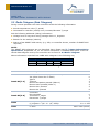
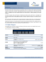
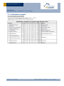
2.5 EO3000I
For this application note the Dolphin Chip Version 1.2 was used. The table below indicates
the typical (@25°C) current consumption values, which are the basis for all considerations.
Operating mode
Deep Sleep (VDD3.3V)
Short Term Sleep
CPU Standby (XTAL on)
CPU mode
Analogue measurement
Receiving
Transmitting (6dBm, 50%duty cycle)
Table 3- Dolphin current
© EnOcean | www.enocean.com
Current consumption (@25°C)
220nA
8 uA
1.4mA
3.7mA
14mA
27,4mA
23,4mA
consumption per mode
Subject to modifications | Marian Hönsch | July 2011 | Page 29/ 54
APPLICATION NOTE 501
SMART ACK –
BI-DIRECTIONAL THERMOSTAT WITH DISPLAY
3 SMART ACK controller
The SMART ACK controller has the following features:
TCM300 module with Dolphin chip
Buttons for user control (Clear, Learn)
LED for user indications
Serial interface (e.g. to trace radio on DolphinView)
Simulates the target temperature settings (T_target)
Figure 29 - SMART ACK controller overview
3.1 Functionality
The SMART ACK controller is the counterpart to the SMART ACK sensor. In a real application it would possibly act as gateway receiving data and forwarding it to e.g. a building
network. In the case of a room controller the information would then e.g. land at a HVAC
control system. This system would then generate the data to be returned to the SMART
ACK sensor. In this demonstration all receive radio telegrams are output to the serial interface. The controller allows to learn-in the sensor. Once the system sensor – controller is
learned-in the controller sends back the temperature setting value (T_target) to the sensor.
3.1.1 FLASH usage
The behaviour of the controller depends if sensors have been learned-in or not. The controller stores information about learned sensors in its FLASH memory.
typedef struct
{
uint32
u32SensorId;
uint32
u32PostMasterId;
uint8
u8LearnCount;
}LEARNED_SENSORS;
LEARNED_SENSORS smSensors[MAX_SMACK_SENSORS];
NOTE:
To avoid undefined behaviour it is important that the learn-in / learn-out status remains
© EnOcean | www.enocean.com
Subject to modifications | Marian Hönsch | July 2011 | Page 30/ 54
APPLICATION NOTE 501
SMART ACK –
BI-DIRECTIONAL THERMOSTAT WITH DISPLAY
synchronized between controller and sensor. This might cause unexpected effects, e.g. if
one side is reprogrammed and therefore, by default not learned-in.
3.1.2 Initialisation and main loop
If the module is Reset or after a power up the software first initializes the chip. Then it
reads the information about learned sensors out of the FLASH memory (see 3.1.1 FLASH
usage) and the threshold for a ―good enough‖ radio signal is initialized. Next the radio is
enabled to receive radio telegrams. Finally the default temperature setting (T_target) is set
to 18°C and the main loop is entered.
During the main loop the watchdog timer is cleared. Then it is checked if a radio telegram
was received. If a radio telegram was received the telegram gets processed see 3.1.3 Radio Processing.
Next the state of LEARN button polled. Pressing the LEARN button toggles between entering
and ending SMART ACK learn mode.
Next the state of the CLEAR button is polled. In case its pressed the temperature set value
is reset to its default value of 18°C.
Finally the SMART ACK processing is executed, see 3.1.4 SMART ACK processing.
© EnOcean | www.enocean.com
Subject to modifications | Marian Hönsch | July 2011 | Page 31/ 54
APPLICATION NOTE 501
SMART ACK –
BI-DIRECTIONAL THERMOSTAT WITH DISPLAY
Reset
EO3000I Init
Read FLASH values
(Sensor table)
Set Good enough RSSI
threshold
Enable Radio
Set Ttarget to 18°C
Clear Watchdog
Radio Telegram
received?
yes
Radio processing
no
LEARN button
pressed?
yes
Toggle LearnMode
no
no
Turn Learn mode off
LearnMode is
active?
yes
Turn LMI Led on
Turn simple Learn
mode on (30s timeout)
CLEAR button
pressed?
no
yes
Set Ttarget to 18°C
SMACK processing
Figure 30 - SMART ACK controller flowchart
© EnOcean | www.enocean.com
Subject to modifications | Marian Hönsch | July 2011 | Page 32/ 54
APPLICATION NOTE 501
SMART ACK –
BI-DIRECTIONAL THERMOSTAT WITH DISPLAY
3.1.3 Radio Processing
Received radio telegrams are indicated with the radio LED (ADIO5) and the telegram data
is output on the serial interface (e.g. for DolphinView). The controller now has to check if
the received telegram was send to him (from a learned sensor).
In case it was from a learned sensor the ―known sensor‖ LED (CH1) is toggled and depending on the received command the T_target value is modified and return data is prepared
and ―send‖. To ―send‖ the return data the smack_sendDataTelegram() API function is used
(not radio_sendTelegram()). The smack_sendDataTelegram() API function sends the data
to the post master, which put the data into a mail box for the receiving sensor (see 1.3.4
Normal operation). This means in case the controller itself acts as post master the telegram is not actually send, but stored in the mail box. Otherwise if the post master is located on a different controller the telegram is send via radio.
Radio processing
Toggle Radio LED
Output radio telegram
on serial interface
Telegram from a
learned sensor?
yes
Toggle „known Sensor―
(CH1)
no
Sensor SET+
pressed?
yes
no
Sensor SETpressed?
no
Increment Ttarget
yes
Decrement Ttarget
Prepare Return data
telegram
„send― return data
telegram
no
Next sensor
All sensors
checked?
yes
End
Figure 31 – Radio processing flowchart
© EnOcean | www.enocean.com
Subject to modifications | Marian Hönsch | July 2011 | Page 33/ 54
APPLICATION NOTE 501
SMART ACK –
BI-DIRECTIONAL THERMOSTAT WITH DISPLAY
3.1.4 SMART ACK processing
Due to the complexity of the SMART ACK handling its not possible to execute all task during
interrupt processing. That why all the time critical routines are executed by the API during
interrupts and some of the none time critical routings have to be manually triggered by the
application software (smack_processController(&u8ShadowBuffer)).
Triggering the SMART ACK process controller returns the state of the SMART ACK controller
which is evaluated. If the SMART ACK process controller
Is in idle state (SMACK_OK) all LEDS regarding learn mode are turned off
Learn mode (simple or advanced) the LMI LED is turned on
Has finalized Learn mode (RESULT_READY) the actual learn routine is called
Has exited learn mode after the learn mode timeout the LMI LED it turned off.
SMACK processing
Execute SMACK tasks
Status is SMACK_OK?
yes
no
LMI Led off
Learn In Led off
Status is
LEARN_ON_SIMPLE?
yes
no
Learn Out Led off
Status is
LEARN_ON_ADVANCDED
yes
LMI Led on
no
Status is
RESULT_READY?
yes
no
Execute Learn
Status is
LEARN_TIMEOUT?
no
yes
Toggle LearnMode
LMI Led off
End
Figure 32 - SMART ACK processing flowchart
© EnOcean | www.enocean.com
Subject to modifications | Marian Hönsch | July 2011 | Page 34/ 54
APPLICATION NOTE 501
SMART ACK –
BI-DIRECTIONAL THERMOSTAT WITH DISPLAY
3.1.5 ExecuteLearn processing
The Dolphin API handles all collection of the learn telegrams and provides a learn result to
the application. The application has to decide what to do learn-in, learn-out or to discard
the learn.
Execute Learn
Get result of SMACK
learn process
Is sensor already a
learned sensor?
LEARN OUT
yes
LearnOut LED on (CH2)
LearnIn LED off (CH3)
no
Next sensor
Inform API that sensor
is learned out
no
All sensors
checked?
Delete Sensor from
learned sensor list
yes
Radio signal is
good enough and
memory sufficient
to learn in the
sensor?
Update learned sensor
list in FLASH memory
yes
End
Find a free entry in
learned sensor list
LEARN IN
no
Found a free entry
yes
LearnIn LED on (CH3)
LearnOut LED off (CH2)
no
Inform API that sensor
is discarded
Inform API that sensor
can’t be learned
End
Add Sensor to
learned sensor list
Inform API that sensor
is learned out
Update learned sensor
list in FLASH memory
End
End
Figure 33 – ExecuteLearn flowchart
© EnOcean | www.enocean.com
Subject to modifications | Marian Hönsch | July 2011 | Page 35/ 54
APPLICATION NOTE 501
SMART ACK –
BI-DIRECTIONAL THERMOSTAT WITH DISPLAY
First the result of the learn process is requested. Then it is check if the sensor was already
learned-in previously. In case it was already learned-in it is learned-out. The Learn Out LED
(CH2) is turned on. The API is informed that it was decided to learn-out the sensor. The
sensor is deleted from the learned sensor list and the list is stored (backup) in FLASH
memory.
In case the sensor was not learned-in already the quality of the radio link is evaluated and
if there is sufficient memory space to learn (store) a further sensor. If not the API is informed that the learn is discarded because of either radio link quality or memory limitations.
If the radio link quality was good enough and there is space a free entry in the learned sensor list is search. In case there is no space the API is informed and the learn is discarded.
Otherwise the learn-in is performed by turning on the LearnIn LED (CH3), adding the sensor to the learned sensor list. Then the API is informed that the sensor was learned-in and
the learned sensor list is stored (backup) in FLASH memory.
3.2 Radio Telegram
The SMART ACK controller sends the following information back to the SMART ACK sensor:
Temperature set value T_target
This information is packed into a 4BS radio telegram in the following way
4BS Telegram
Choice
1byte
Data3..0
4byte
SrcId Status
4byte 1byte
Checksum
1byte
Choice
4BS telegram
Fehler! Verweisquelle konnte nicht gefunden werden. 0xA5
Data3
Not used
Fehler! Verweisquelle konnte nicht gefunden werden. 0xAF
Data2
Not used
0xFE
Data1
Temperature target value
0..40°C
Data0
Bit3 is set to 1 to be compliant with
EnOcean Equipment Profiles (EEP)
Bit3 = 0 teach-in telegram
Bit3 = 1 data telegram
0xFF..0x00 (linear)
0x08
Status
32bit ID of telegram source
0x0000_0001..0xFFFF_FFFF
Fehler! Verweisquelle konnte nicht gefunden werden.
Reserved
0x0000_0000
Status information
Fehler!
field Verweisquelle konnte nicht gefunden werden. 0x00
Checksum
Checksum of theFehler!
radio telegram
Verweisquelle konnte nicht gefunden
Calculated
werden.
checksum
SrcID
© EnOcean | www.enocean.com
Subject to modifications | Marian Hönsch | July 2011 | Page 36/ 54
APPLICATION NOTE 501
SMART ACK –
BI-DIRECTIONAL THERMOSTAT WITH DISPLAY
4 Getting Started (“Run the demo”)
This chapter describes how to setup and run the demo.
4.1 System requirements
To operate the demo you need to have the following components:
EVA300 – Evaluation board TCM300 (part of EDK300)
EVA320 - Evaluation board STM300 (part of EDK300)
EOP300 Programmer with USB cable
PC with Windows and a free USB port
Demo software, e.g. on EDK300 CDROM
Optional LCD Display (RCD board)
Note: The demo can be operated without an attached LCD Display, however with reduced
functionality.
4.2 Step-by-step
The following step-by-step guide will help you to setup the demo. First a list of the necessary steps is given (for the experienced user) and afterwards the step details are explained
(for first time user and for reference).
4.2.1 Download SMART ACK controller software
4.2.2 Download SMART ACK sensor software
4.2.3 Learn-in sensor
4.2.4 Monitor communication using
Now the demo is ready to be used!!!
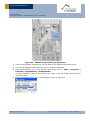
4.2.1 Download SMART ACK controller software
To setup the SMART ACK controller the necessary software needs to be downloaded into
the TCM module.
1. Ensure EVA300 Jumper settings according to Figure 34
© EnOcean | www.enocean.com
Subject to modifications | Marian Hönsch | July 2011 | Page 37/ 54
APPLICATION NOTE 501
SMART ACK –
BI-DIRECTIONAL THERMOSTAT WITH DISPLAY
Figure 34 - EVA300 Programming Configuration
2. Connect the EOP300 Programmer via flat cable to the EVA300 Evaluation board
3. Connect the EOP300 Programmer to the PC using the USB cable
4. Start DolphinStudio e.g. in the Window start menu select - Start | Programs |
EnOcean | DolphinStudio | DolphinStudio
(its also possible to use the Keil uVision tool chain to do the FLASH download (not
described here))
5. Select Programmer port - from the dropdown menu in upper left
© EnOcean | www.enocean.com
Subject to modifications | Marian Hönsch | July 2011 | Page 38/ 54
APPLICATION NOTE 501
SMART ACK –
BI-DIRECTIONAL THERMOSTAT WITH DISPLAY
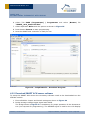
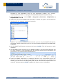
6. Select Tab EOPX (Programmer) | Programmer and select (Browse) file
“SMART_ACK_Controller.hex”
7. Select Operation Write with the options as shown in Figure 35
8. Press button Execute to start programming
9. Now the SMART ACK controller is ready for use.
Figure 35 - DolphinStudio - Download Program
4.2.2 Download SMART ACK sensor software
To setup the SMART ACK sensor the necessary software needs to be downloaded into the
STM300 module.
1. Ensure EVA320 Jumper and Switch settings as shown in Figure 36
2. Bridge storage voltage trigger signal with DVDD
The bridge shown in Figure 37 is mandatory for proper operation of the demonstration (not required for programming). The WXIDIO signal is used for the LCD Display
© EnOcean | www.enocean.com
Subject to modifications | Marian Hönsch | July 2011 | Page 39/ 54
APPLICATION NOTE 501
SMART ACK –
BI-DIRECTIONAL THERMOSTAT WITH DISPLAY
power control (on the evaluation board it is used to trigger long term storage voltage measurement)
Figure 36 - EVA320 Programming Configuration
Figure 37 - Bridge DVDD - trigger storage voltage
© EnOcean | www.enocean.com
Subject to modifications | Marian Hönsch | July 2011 | Page 40/ 54
APPLICATION NOTE 501
SMART ACK –
BI-DIRECTIONAL THERMOSTAT WITH DISPLAY
3. Connect the EOP300 flat cable to the EVA300 Evaluation board
4. Connect the EOP300 Programmer to the PC using the USB cable
5. Start DolphinStudio Start | Programs | EnOcean | DolphinStudio | DolphinStudio
(its also possible to use the Keil uVision tool chain to do the FLASH download (not
described here))
6. Select Programmer -
from the dropdown menu in upper left
menu Tools | Options
7. Select EOPX (Programmer)
“SMART_ACK_Sensor.hex”
|
Programmer
and
select
(Browse)
file
8. Select Operation Write with the options as shown in Figure 35
9. Press button Execute to start programming
10. Now the SMART ACK sensor is ready for use.
For testing it might be easier to continue using the USB as power supply.
To operate the sensor in energy autarkic way do the following steps:
1. switch power switch to OFF
2. disconnect EOP300 programmer (flat cable)
3. change Jumper ―Energy source‖ to SOLAR
4. switch power switch to ON
4.2.3 Learn-in sensor
The learn process established the relationship between the SMART ACK sensor with the
SMART ACK controller. It also defines a post master.
1. On the SMART ACK controller press the LEARN button -> Led LMI should turn on
Note: Learn mode is automatically exited after a timeout of 30s
2. On the SMART ACK sensor press LRN button -> this will send a learn request message
3. On the SMART ACK controller the LED CH3 should turn on - indicates ―Learned-in‖
(Led CH2 indicates ‖Learned-out‖)
4. On the SMART ACK controller press LEARN button to finalize and exit learn mode
LMI Led will turn off
5. Now the learn process is completed
4.2.4 Monitor communication using DolphinView
To monitor the communication between controller and sensor the DolphinView software can
be used.
1. Copy the SmartackDemo.xml file to your DolphinView\Resources folder. This file
helps DolphinView to interpret data from SMART ACK Controller and Sensor. In the
© EnOcean | www.enocean.com
Subject to modifications | Marian Hönsch | July 2011 | Page 41/ 54
APPLICATION NOTE 501
SMART ACK –
BI-DIRECTIONAL THERMOSTAT WITH DISPLAY
firmware of the application note we use proprietary profiles. (e.g. Controller\SmartackDemo.xml to C:\Program Files\EnOcean\DolphinView\Resources).
2. Start DolphinView, e.g. menu START | Programs | EnOcean | DolphinView |
DolphinView 3.1.1.0
3. Select the port of the SMART ACK Controller or select the port of the third device
which can be for example a Gateway Controller.
NOTE: If you select the SMART ACK Controller you see only the SMART ACK Sensor
telegrams. With a third device you can see and visualize telegrams from SMART ACK
Controller.
4. On the SMART ACK Sensor now press the button OCCUP. This will transmit a radio
message.
5. On the SMART ACK controller the Led ADIO5 indicates a received radio telegram and
Led CH1 indicates a radio telegram from the learned sensor and the telegrams will
be output on the serial interface (DolphinView)
6. Select the SMART ACK Sensor in Unassigned and but it by a left double click to the
Workspace. Be sure the device is selected. If you cannot identify the SMART ACK
Sensor, you can look for a flash (RED) that can be seen after a telegram from it is
received. Pressing button OCCUP. triggers the Sensor to send a telegram.
© EnOcean | www.enocean.com
Subject to modifications | Marian Hönsch | July 2011 | Page 42/ 54
APPLICATION NOTE 501
SMART ACK –
BI-DIRECTIONAL THERMOSTAT WITH DISPLAY
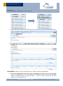
7. Select EEP View TAB and in Profiles select the previously copied SmartackDemo.xml.
8. In TYPE Select the *** Smart Ack Sensor Demo Telegram *** click on the Set
Profile button. Then you should see the data send from SMART ACK Sensor visually
interpreted.
OPTIONALLY when you have a third device to capture radio communication
9. Select the SMART ACK Controller in the Unassigned list and put it by a left double
click to the Workspace. You can identify the controller as the device that answers
(sends a telegram) after you press the SET – or SET + button. The device will flash
(RED) in the Unassigned list.
© EnOcean | www.enocean.com
Subject to modifications | Marian Hönsch | July 2011 | Page 43/ 54
APPLICATION NOTE 501
SMART ACK –
BI-DIRECTIONAL THERMOSTAT WITH DISPLAY
10. Select the SMART ACK Controller in the Workspace list and set the profile ***
Smart Ack Controller Demo Telegram *** on this device.
11. By selecting the SMART ACK Sensor or SMART ACK Controller you will see their data
history and visual interpretation.
© EnOcean | www.enocean.com
Subject to modifications | Marian Hönsch | July 2011 | Page 44/ 54
APPLICATION NOTE 501
SMART ACK –
BI-DIRECTIONAL THERMOSTAT WITH DISPLAY
5 Outlook
This application note demonstrated the operation of a basic bi-directional room controller
with LCD display and SMART ACK. The provided software and documentation shall make it
easy to get familiar with the topic and starting own development based on this.
Further optimizations on the software and hardware side could e.g. be
Handling of redundant transmissions - only send if measurement value have changed
(store measurement values in RAM0)
keep alive messages (if no change in measured value for x times then send anyway)
detect light level, e.g. when its night to reduce send frequency
reduce amount of radio traffic related to increase/decrease of temperature set value
(T_target)
usage of different display technology, e.g. bi-stable displays (ePaper)
optimization of the energy management circuitry regarding SMART ACK requirements
Another aspect not mentioned before is the use of remote management as diagnostics tool
and to solve issues. Due to the complexity induced through bi-directional communication, in
particular the relationship between sensor, controller and post master, there are multiple
source for errors or unexpected behavior (e.g. if the repeater acting as post master is exchanged or moved).
First sophisticated Remote Management tools are already developed which can help to analyze and solve those types of problem.
© EnOcean | www.enocean.com
Subject to modifications | Marian Hönsch | July 2011 | Page 45/ 54
APPLICATION NOTE 501
SMART ACK –
BI-DIRECTIONAL THERMOSTAT WITH DISPLAY
6 Table of content
1
2
Introduction ........................................................................................................ 1
1.1
Purpose ....................................................................................................... 1
1.2
Demo system: Bi-directional room controller .................................................... 2
1.3
Smart Acknowledge ....................................................................................... 4
1.3.1
Why SMART ACK ..................................................................................... 4
1.3.2
How does SMART ACK work (principle only) ............................................... 5
1.3.3
Learn process (learn-in / learn-out)........................................................... 6
1.3.4
Normal operation .................................................................................... 6
1.4
Demo Limitations .......................................................................................... 8
1.5
References ................................................................................................... 8
SMART ACK sensor (room controller) ...................................................................... 9
2.1
Functionality............................................................................................... 10
2.1.1
FLASH and RAM0 usage ......................................................................... 10
2.1.2
Power On ............................................................................................. 11
2.1.3
Reset / Wakeup .................................................................................... 11
2.1.4
Action Init ............................................................................................ 13
2.1.5
Action Timeout ..................................................................................... 13
2.1.6
Action Occupation ................................................................................. 14
2.1.7
Action Ignore ....................................................................................... 14
2.1.8
Action LEARN ....................................................................................... 15
2.1.9
Action SET + / SET - ............................................................................. 15
2.2
Radio Telegram (Data Telegram) .................................................................. 18
2.3
Display ...................................................................................................... 19
2.3.1
Hardware interface ................................................................................ 20
2.3.2
SPI Protocol ......................................................................................... 21
2.3.3
Graphical display .................................................................................. 21
2.3.4
Energy efficient LCD display operation (Challenges) .................................. 23
2.3.5
Handling of LCD display supply range (used method) ................................ 25
2.3.6
Handling of LCD display supply range (optional method) ............................ 25
2.3.7
Start-up time – dimensioning of CVDD ....................................................... 26
2.3.8
Start-up time - STM300 Firmware requirements ....................................... 27
2.3.9
Start-up time - SMART ACK requirements ................................................ 27
2.4
How to evaluate Energy consumptions ........................................................... 27
© EnOcean | www.enocean.com
Subject to modifications | Marian Hönsch | July 2011 | Page 46/ 54
APPLICATION NOTE 501
SMART ACK –
BI-DIRECTIONAL THERMOSTAT WITH DISPLAY
2.4.1
2.5
3
EO3000I .................................................................................................... 29
SMART ACK controller ......................................................................................... 30
3.1
Functionality............................................................................................... 30
3.1.1
FLASH usage ........................................................................................ 30
3.1.2
Initialisation and main loop .................................................................... 31
3.1.3
Radio Processing ................................................................................... 33
3.1.4
SMART ACK processing .......................................................................... 34
3.1.5
ExecuteLearn processing ........................................................................ 35
3.2
4
Measurement setup ............................................................................... 27
Radio Telegram ........................................................................................... 36
Getting Started (―Run the demo‖) ........................................................................ 37
4.1
System requirements .................................................................................. 37
4.2
Step-by-step .............................................................................................. 37
4.2.1
Download SMART ACK controller software ................................................ 37
4.2.2
Download SMART ACK sensor software .................................................... 39
4.2.3
Learn-in sensor..................................................................................... 41
4.2.4
Monitor communication using DolphinView ............................................... 41
5
Outlook ............................................................................................................. 45
6
Table of content ................................................................................................. 46
7
Appendix EA DOGM132-5 .................................................................................... 48
8
7.1
Command table .......................................................................................... 48
7.2
Initialization example .................................................................................. 49
Appendix room controller display.......................................................................... 50
8.1
Schematics................................................................................................. 50
8.2
Bill Of Material ............................................................................................ 51
8.3
Layout ....................................................................................................... 52
© EnOcean | www.enocean.com
Subject to modifications | Marian Hönsch | July 2011 | Page 47/ 54
APPLICATION NOTE 501
SMART ACK –
BI-DIRECTIONAL THERMOSTAT WITH DISPLAY
7 Appendix EA DOGM132-5
7.1 Command table
© EnOcean | www.enocean.com
Subject to modifications | Marian Hönsch | July 2011 | Page 48/ 54
APPLICATION NOTE 501
SMART ACK –
BI-DIRECTIONAL THERMOSTAT WITH DISPLAY
7.2 Initialization example
© EnOcean | www.enocean.com
Subject to modifications | Marian Hönsch | July 2011 | Page 49/ 54
APPLICATION NOTE 501
SMART ACK –
BI-DIRECTIONAL THERMOSTAT WITH DISPLAY
8 Appendix room controller display
8.1 Schematics
© EnOcean | www.enocean.com
Subject to modifications | Marian Hönsch | July 2011 | Page 50/ 54
APPLICATION NOTE 501
SMART ACK –
BI-DIRECTIONAL THERMOSTAT WITH DISPLAY
8.2 Bill Of Material
The list below lists the used components and provides one possible supplier as reference.
Quantity
Reference
5
C1, C2, C3,
C4, C5
4
1
2
1
1
1
1
2
Description
Comment
Ceramic capacitor
100nF, 16V, 10%
SMD-0805
Ceramic capacitor
C6, C7, C8, C9 1uF, 16V, 10%
SMD-0805
C10, C11, C12 Not populated
Electrolyte capacitor
C13
1000uF, 5V
RM 5,08mm
Resistor
R1, R5
1M, 5%, 0.125W
SMD-0805
R2
Not populated
Resistor
R3
470K, 5%, 0.125W
SMD-0805
Resistor
R4
100K, 5%, 0.125W
SMD-0805
Resistor
R6
0R, 5%, 0.125W
SMD-0805
P FET Transistor
Q1
BSS84
SMD-SOT23
N FET Transistor
Q2, Q3
BSS138
SMD-SOT23
Q4
Not populated
Pin header 1x2
JP1, JP2
RM 2,54mm
Not populated
SV1, SV2
Pin socket 1x27
Display
LCD display
EA-DOGM
© EnOcean | www.enocean.com
Only for mechanical
inteconnection
One pin needs to be cut
off
Subject to modifications | Marian Hönsch | July 2011 | Page 51/ 54
APPLICATION NOTE 501
SMART ACK –
BI-DIRECTIONAL THERMOSTAT WITH DISPLAY
8.3 Layout
Figure 38 – Top Silk
Figure 39 – Top Placement
Figure 40 – Top Solderpaste
© EnOcean | www.enocean.com
Subject to modifications | Marian Hönsch | July 2011 | Page 52/ 54
APPLICATION NOTE 501
SMART ACK –
BI-DIRECTIONAL THERMOSTAT WITH DISPLAY
Figure 41 – Top Solderstop
Figure 42 - Top
Figure 43 - Bottom
Figure 44 – Bottom Solderstop
© EnOcean | www.enocean.com
Subject to modifications | Marian Hönsch | July 2011 | Page 53/ 54
APPLICATION NOTE 501
SMART ACK –
BI-DIRECTIONAL THERMOSTAT WITH DISPLAY
Figure 45 –Bottom Solderpaste
Figure 46 – Bottom Placement
© EnOcean | www.enocean.com
Subject to modifications | Marian Hönsch | July 2011 | Page 54/ 54