1
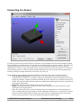
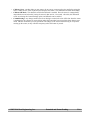
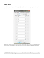
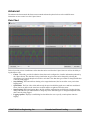
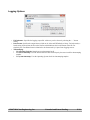
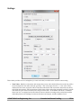
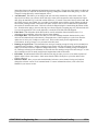
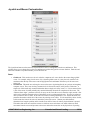
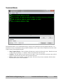
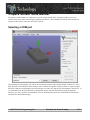
3-Space Sensor Suite Manual
The purpose of this manual is to explain how to use the 3-Space Sensor Suite, a program which gives access to
features of the sensor and its data through a graphical user interface. The information contained in this document is
accurate for all versions of the suite from 3.0r1 onwards.
Selecting a COM port
Upon running the suite program, you will see an area along the bottom of the window labeled “Connection”, with a
drop down list of all COM ports on the machine, some of which correspond to 3-Space Sensors or 3-Space Dongles.
Select the COM port corresponding to the sensor/dongle you wish to use, and the suite will attempt to connect to it. If
you would like to use the terminal mode to communicate directly with the chip instead of using the graphical
interface, go to File->Switch to Terminal Mode. Bear in mind that this mode is more technical and is intended for
advanced users and troubleshooting.
©2007-2014 Yost Engineering, Inc.
Patended and Patent Pending
1/16
Connecting to a Sensor
If a sensor is present on the selected COM port, the features on the right hand side of the window should be enabled.
The first thing that you should take note of is the large area in which an image of the sensor appears. This image will
rotate along with the sensor as you move it, and will be your best indication of whether the sensor is properly
calibrated or not. There are red, green and blue arrows to represent where the sensor's local positive X, Y, and Z axes
are(by default) respectively. Take note that the default orientation for the sensor is the green arrow pointing up, the
red arrow pointing to the right, and the blue arrow facing away from you.
Along the side are some of the more common commands you can issue to the sensor. From top to bottom:
• The Components Enabled list. This allows you to see how the sensor will perform with some of its
component sensors turned off. For example, with the gyros disabled, the sensor will respond more slowly to
changes in orientation. With the accelerometer disabled, the sensor will jitter less, but will be missing an axis
of data. This list also includes MI mode, which once calibrated and enabled grants the sensor protection from
some magnetic disturbances.
• LED Color. Move the sliders to change the color of the sensor's LED.
• Display. This determines what is shown in the main window, allowing you to turn on and off the sensor
model and arrow being drawn there.
• Tare. Tare chooses the sensor's current orientation as the zero orientation(the one where it thinks the red
arrow is pointing right, the green pointing up, and the USB plug towards the user). You will want to check to
make sure the sensor appears this way on the screen when you have it in that position in the real world as
soon as you start up the suite. If not, put it in that position and press the Tare button.
©2007-2014 Yost Engineering, Inc.
Patended and Patent Pending
2/16
•
•
•
Calibrate Gyros. Another thing you may want to do as soon as you start up the suite, and before taring the
sensor. Make sure the sensor is perfectly still and press the button. The calibration will finish immediately.
Calibrate MI Mode. This should be used before MI mode is enabled. Place the sensor in a magnetically
unperturbed area and select this, leaving the sensor in that area for 3-4 seconds. After this, this calibration
can be saved using the Commit Settings option, and MI mode can be enabled.
Commit Settings. Any changes made to the sensor during a session in the suite will be lost when the sensor
is unplugged or the computer is powered down unless this button has been pressed after those changes were
made. This also means that you can experiment with changes to the sensor without having to worry about
messing up the sensor, as they will all be temporary unless this button is pressed.
©2007-2014 Yost Engineering, Inc.
Patended and Patent Pending
3/16
Connecting to a Dongle
When connecting to a dongle, the sensor options on the right will remain disabled while the dongle is not connected to
a wireless sensor. The “Sensor Select” box will become available when connected to a dongle. This allows you to
select which sensor address the suite communicates to through the dongle. If it is set to “None”, the dongle will not
try to communicate with any sensor, but will remain connected to the Suite so other dongle settings may be changed.
If there is a wireless sensor at that address and the pan id and channel match on the dongle and the wireless unit, the
dongle should connect to the wireless sensor. The suite may then be used to communicate with that sensor in the same
way as a wired sensor.
©2007-2014 Yost Engineering, Inc.
Patended and Patent Pending
4/16
Sensor Menu
On the menu bar, the first item you will see after file is Sensor. This contains commands that are useful, but not quite
as common as those that appear on the main window. In Other Commands, we have:
• Sensor Info(and Wireless Settings). This screen will display the sensor's serial number and version string.
If it is a wireless sensor, it will also let you see and change the pan ID and channel. If it is a wired sensor, this
is where options for HID emulation(joystick and mouse) may be found.
• Run Gradient Descent Wizard. This wizard will help you calibrate the compass and accelerometer. First, a
screen will appear asking you to select which component sensors you would like to calibrate.
After choosing begin, the wizard will display a picture of the sensor that will show you an orientation you
should put the sensor in.
Put the sensor in that orientation and press Next, making sure to hold the sensor still until the picture moves
to a new orientation. The sensor will then move on to indicate the next orientation in which you should put
the sensor. There are 24 orientations to collect data from. Please note that these changes will not be saved
permanently to the sensor unless settings are committed.
©2007-2014 Yost Engineering, Inc.
Patended and Patent Pending
5/16
•
•
•
•
Run Sphere Calibration Wizard. This wizard will walk you through collecting a relatively complete set of
magnetometer data from which sensor parameters can be calculated. This calibration method is not as
accurate as gradient descent, but can be performed more quickly. When performing calibration, a large
sphere will appear that represents possible magnetometer vectors that will be collected as the sensor is
rotated.
A cyan arrow will appear, which will mark areas of the sphere that have been touched with a cyan color.
During this type of calibration, the sensor can be moved as quickly as you like until the sphere is mostly
colored cyan. At the bottom of the window, there will be an indicator showing the number of total data
samples collected as well as the estimated density, which is a measure of how filled in the sphere is. This
number will start at approximately 180 and decrease as more samples are collected. Typically, a good
calibration is achieved when the density reaches a level of 30 – 50 and the sphere is mostly colored in. When
the data set seems complete hit the finish button. If you want to start over, hit reset. If you want to quit
without calibrating using the data, hit cancel. Please note that these changes will not be saved permanently to
the sensor unless settings are committed.
Restore Factory Settings. If you want to restore the sensor to how it was originally, erasing any changes
you have made to it, use this command. Please note that if you want to keep the sensor in this state once you
have used this command, you need to press the Commit Settings button. Otherwise, the sensor will return to
the state it was in prior to the run of this command when it next boots up.
Save/Load Settings to/from File. These options will let you save sensor settings to a file, or load settings
onto the sensor from a file. When saving you will be given choices as to which settings you would like to
save.
Update Firmware. This will update the firmware of the sensor. It will let you choose an xml file that
contains the firmware update data, and then will begin the updating process. The sensor will not be useable
during this time, and some changes that were made to the sensor, regardless of whether they were committed,
will be wiped out, as the firmware updater rewrites that entire area of memory. The exception to this is the
component sensor calibration parameters, which the suite will try to preserve across a firmware update. Do
©2007-2014 Yost Engineering, Inc.
Patended and Patent Pending
6/16
•
not unplug your sensor while this process is occurring, as it will leave the firmware in an indeterminate state.
If something does go wrong during this process, you may close the suite and run it again. If the suite detects
an incomplete program on the sensor, it will give you the option to try to update the firmware again. You will
not be able to use the sensor normally until a complete set of firmware has been written to it.
Reset Sensor. This will reset the sensor, causing any uncommitted changes on the sensor to be wiped out.
©2007-2014 Yost Engineering, Inc.
Patended and Patent Pending
7/16
Bootloader Menu
If a firmware update fails, the sensor or dongle will be left in bootloader mode and will display a red LED
color. This menu gives you the option to try to update the firmware again, or, in some cases, to return to the previous
firmware. If a firmware write began in the past but did not complete, you will not be able to return to the firmware
until a firmware update succeeds.
©2007-2014 Yost Engineering, Inc.
Patended and Patent Pending
8/16
Dongle Menu
This menu provides options for the dongle. The only difference between the options provided here and the
same options provided on the sensor menu is that the Wireless Communication Settings screen also includes address
slots.
On this screen, enter the serial number of a wireless sensor into the address slot you would like to communicate with it
on. You may later select that address in the Sensor Select box on the main window to communicate with that sensor.
©2007-2014 Yost Engineering, Inc.
Patended and Patent Pending
9/16
Advanced
The Advanced sub-menu under the Sensor menu contains advanced options for those who would like more
information or more control over the 3 Space Sensor.
Data Chart
This tool provides various visualizations of the data that can be read from the 3 Space Sensor as well as the ability to
log this data to a file.
• Charts. This utility provides four distinct charts that can be configured to visualize information produced by
the 3 Space Sensor. The data that is being visualized at any given time can be changed by selecting the
desired data type from the dropdown box above each chart. Note that data types cannot be changed while data
is actively being logged.
• Stop Charting. This button allows charting to be stopped and started, but has no affect on any active data
logging itself.
• Speed Slider. The Fast->Slow slider affects only the speed at which the graph moves and how much data it
shows, but has no affect on the actual rate at which samples are gathered from the sensor.
• Start Logging. Will begin logging data to the file using the configuration specified in the Logging Options
dialog box. Note that you will be unable to change any of the chart data types or configuration options while
data is actively being logged.
• Logging Options. Displays a small dialog box that allows the user to specify certain options related to
logging.
©2007-2014 Yost Engineering, Inc.
Patended and Patent Pending
10/16
Logging Options
•
•
•
File Pathname. Specifies the logging output file. A directory can be chosen by selecting the “...” button
nearby.
Data Format. Specifies the output format, which can be either ASCII(Default) or binary. For both modes, a
header string is placed into the file on the first line which indicates the overall format of the file. For
simplicity, the overall data format is identical to the format used by 3 Space Data Logging sensors.
Timestamping.
• No timestamp (Default). Samples are not timestamped at all.
• Use sensor timestamp. Uses the internal microsecond counter kept by the sensor itself for timestamping
samples.
• Use system timestamp. Uses the Operating System clock for timestamping samples.
©2007-2014 Yost Engineering, Inc.
Patended and Patent Pending
11/16
Settings
This window provides access to settings that you won't need often, but which can be useful for sensor tuning.
•
Trust Values. Both the accelerometer and compass have a trust value which indicates how much they will be
favored compared to each other and to the gyroscope. This value ranges from 0 to 1. A low value of trust
indicates that the sensor in question will be trusted less(which will result in smoother motion but more drift),
and a high value means it will be trusted more(which means jerkier motion but potentially less drift). In static
trust mode, the given sensor will always have the given trust value. In confidence trust mode, a confidence
factor from 0 to 1 is assigned to the sensor based on the acceleration occurring on the accelerometer and the
relationship between the readings from the accelerometer and compass, and this confidence factor
©2007-2014 Yost Engineering, Inc.
Patended and Patent Pending
12/16
•
•
•
•
•
•
interpolates between the minimum and maximum given trust values. The purpose of this mode is to allow the
gyroscope to take over when the accelerometer is giving readings that include more than gravity, or when the
compass is being affected by unusual magnetic forces.
Axis Directions. This allows you to change what axis each of the natural axes of the sensor read as. The
drop-down box allows you to choose which side of the sensor will correspond to each component of output
data. Keep in mind that “Up” is the side with an LED on it, “Forward” is the side of the top of the board that
the LED is closest to, and “Right” is to your right if you hold the sensor with the up side pointing up and the
forward side pointing forward. This feature is in place for those who are used to different axis systems than
the one that is natural to this sensor. Each axis can also be flipped using the controls along the bottom of this
box. Note that these apply to the axes after they have been swapped, so negating any axis will switch the side
it is on to the opposite(so if X is on the right side, it would be on the left side while flipped).
Filter Mode. This determines which filter mode is used for orientation fusion inside the sensor. For
information about each filter, refer to the 3-Space Sensor Manual.
Oversample Rate. This determines how many sets of sensor readings should be obtained each cycle to
derive the orientation from, broken down by component sensor. More samples per cycle slows down the
update rate of each cycle, but helps to reduce error. This is useful mostly for the magnetometer and
accelerometer, as the gyroscope is very accurate in the short term.
Running Average Percent. This determines how strong of a running average is being used on orientation or
component sensor readings. A higher running average percent will cause the output to be smoother and less
shaky, but will also cause it to respond to changes more slowly. 0 means no running average will happen at
all, and larger values(up to the maximum of 100) will cause the running average to become stronger. As with
the oversample rate, this is mostly useful for the magnetometer and accelerometer.
LED Mode. Normal means that the LED will show not only the color you set it to, but other sequences of
lights in order to show sensor status. Static means that the LED will only show your color and no other
activity will occur.
Reference Modes. Here you can switch which kind of reference vector scheme is being used, and can
change the reference vectors if it is in manual mode. For more information on these, refer to the User's
Manual for your sensor version.
©2007-2014 Yost Engineering, Inc.
Patended and Patent Pending
13/16
Joystick and Mouse Customization
The joystick and mouse on the sensor are represented as a series of configurable virtual axes and buttons. This
window allows you to change the way the axes and buttons on either the joystick or mouse function. Each axis and
button has a number of operation modes you can choose from.
Axes
•
•
Global Axis. This mode uses as its axis value the component of a vector local to the sensor along a global
vector. For example, using a local vector of (0,1,0) and a global vector of (1,0,0), the axis would be at its
maximum when the top of the sensor was facing right and at its minimum when the top of the sensor was
facing left.
Screen Point. This mode acts as though a vector on the sensor is pointing directly at a point on an imaginary
computer screen. The screen is always assumed to be in front of the sensor, in the positive Z direction. A
single axis of this mode only contains information about a single axis of the screen, i.e. if it was meant for the
x axis of the mouse it would probably only contain information about the X component of this screen. The
“Distance from origin” parameter sets how far away on the Z axis the screen is from the origin, and the “Size
on this axis” parameter determines how wide/tall the screen is on that particular axis. You may use whatever
units you like for these 2 values, as the units will cancel out during calculations. The “Sensor direction axis”
parameter determines which axis of the sensor the pointing vector will be. Z is the most likely choice for this,
as this means the front of the sensor is intended to point at the screen. “Button press halt duration”
determines how long the position on this virtual screen will be frozen for when a physical button is pressed.
This makes this mode more useful as a mouse as it allows mouse selections to be made without as much
movement from the cursor and prevents some cursor motion that occurs due to the physical act of pressing
©2007-2014 Yost Engineering, Inc.
Patended and Patent Pending
14/16
the buttons.
Buttons
•
•
•
Physical Button. This is the simplest of the button modes, as it simply maps one of the virtual buttons
directly to one of the sensor's physical buttons.
Orientation. This mode will activate the virtual button when the specified local vector on the sensor is
pointing in roughly the same direction as a global vector. The “Max Distance” parameter indicates how close
the dot product of the two vectors must be to 1 for the button to activate. For example, if the local axis was
(0,0,1), the global axis was (0,1,0), and the max distance was 1, the button would be activated so long as the
forward direction of the sensor was not pointing downward(as long as it was within 90 degrees of up).
Shake. This mode will cause the button to activate whenever the sensor is shaken. The shake threshold is
the amount it has to be shaken to activate in units of g, where g is equal to the acceleration due to gravity. So,
if the shake threshold is .5, the chip will have to experience an acceleration greater than half the acceleration
due to gravity for the button to activate. Note that due to the nature of acceleration, stable behavior should
not be expected from the resulting button activations. They will occur when the chip is moved a certain
amount and only then, but during that period of time the presses are sporadic.
©2007-2014 Yost Engineering, Inc.
Patended and Patent Pending
15/16
Terminal Mode
Terminal mode allows you to communicate directly with the sensor without the aid of the graphical interface. For
instructions on how to communicate using terminal commands, see the 3-Space Sensor Usage/Protocol section in the
3-Space Sensor User's Manual document.
•
•
•
Main Terminal Window. This box displays all data sent to and received from the sensor. Data that was sent
is white and is preceded by a '>' character. Data received from the sensor is green.
Send Box. The little black box at the bottom of the window. Type text into this box and press enter or Send,
and the text will be sent to the sensor with a newline at the end.
History. While in the Send Box, pressing the up key will retrieve the previous command, while the down
key will return to more recent commands.
©2007-2014 Yost Engineering, Inc.
Patended and Patent Pending
16/16